optics and quantum electronics - rle at mit · chapter 40. optics and quantum electronics 40-4 rle...
TRANSCRIPT
Chapter 40. Optics and Quantum Electronics
40-1
Optics and Quantum Electronics Academic Staff Prof. James G. Fujimoto, Prof. Erich P. Ippen, Professor Franz X. Kärtner Research Staff, Visiting Scientists and Affiliates Dr. Jonathan Birge, Dr. Guoqing Chang, Dr. Yueli Chen, Dr. Yu Chen, Dr. Giovanni Cirmi, Prof. Helder Crespo, Dr. Edilson Falcao-Filho, Dr. Peter Fendel, Dr. Vasileios Gkortsas, Dr. Iwona Gorczynska, Dr. Mikhail Gubin, Dr. Katherine Hall, Prof. T.W. Hansch, Dr. Klaus Hartinger, Dr. Kyung-Han Hong, Dr. R. Holzwarth, Dr. Taegeun Kim, Dr. Florian Loehl, Dr. Frank Ludwig, Prof. Uwe Morgner, Dr. Jeffrey Moses, Dr. Amir Nejadmalayeri, Dr. David Phillips, Dr. Milos Popovic, Dr. Benjamin Potsaid, Dr. Dominik Pudo, Dr. Daniel Ripin, Dr. Alexander Sell, Dr. Luciano Socci, Dr. Hideyuki Sotobayoshi, Dr. Yuankai Tao, Dr. Dimitri Tyurikov, Dr. Tobias Wilden, Prof. Ronald Walsworth, Dr. Yimin Wang, Prof. Zhigang Zhang, Dr. Chao Zhou, Dr. Shin-ichi Zaitsu Graduate Students Gilberto Abram, Desmond Adler, Andrew Benedick, Siddharth Bhardwaj, Hyunil Byun, David Chao, Hung-Wen Chen, Jeff Chen, Li-Jin Chen, Woo John Choi, Jung-Ho Chung, Jonathan Cox, Marcus Dahlem, Umit Demirbas, Xing Fu, Yu Gu, Vasileios Gkortsas, Shu-Wei Huang, Anatoly Khilo, Phillip Keathley, Jung-Won Kim, Martin Kraus, Chien-Jen Lai, Hsiang-Chieh Lee, Duo Li, Jonathan Liu, Chen Lu, Jonathan Morse, Ali Motamedi, Michael Peng, William Putnam, Jeffrey Russom, Michelle Sander, Katia Shtyrkova, Hanfei Shen, Aleem Siddiqui, Alexander Soane, Cheryl Sorace, Tsung-Han Tsai, Jing Wang, Liang Jie Wong Technical and Support Staff Dorothy A. Fleischer, Donna L. Gale Research Areas and Projects
1. Ultrashort Pulse Laser Technology
A . Ultrafast Technologies • Modelocking with Minimum Nonlinearity Using Gain-Matched Output Couplers • Stable 1 GHz Er-fiber Lasers • Integrated Femtosecond Lasers and Interleavers • Noise Optimization of OPCPAs • Cavity Enhanced OPCPA • Highly Efficient Cherenkov Radiation in Photonic Crystal Fibers • 40 mJ, 2kHz Cryogenically Cooled Yb:YAG Chirped-pulse-amplifier
B. Octave-spanning Supercontinuum Generation for an Er-doped Laser Frequency Comb at a GHz Repetition Rate
C. Femtosecond Laser Technology using Single Mode Diode Pumped
Cr:Colquirlite Lasers • Femtosecond Tuning of Cr:Colquirlite Lasers with AlAs/AlGaAs Saturable
Absorbers • Broadband Femtosecond Generation with Cr:LISAF Lasers using Oxidized SBRs • GHz Repetition Rate Femtosecond Cr:LISAF Laser with KW Peak Power
2. Femtosecond Laser Frequency Combs • Visible Wavelength Astro-Comb • Towards a Broadband Astro-Comb • High-Finesse Dispersion-Free Cavities for Broadband Filtration of Laser Comb
Lines
Chapter 40. Optics and Quantum Electronics
40-2 RLE Progress Report 152
• Robust Optimization Algorithm to Improve Thin Film Manufacturing Yield
3. Attosecond Science and High Harmonic Generation • Ultrabroadband Optical Parametric Chirped Pulse Amplification • Scalable, Sub-cycle Pulse Synthesis • High Harmonic Efficiencies Studied with 400 and 800 nm Pulses • Scaling of HHG • Attosecond Pulse Metrology
4. Attosecond Photonics • Quantum-origin Timing Jitter Measurement of Fiber Lasers to the Nyquist
Frequency • Measurement of Attosecond Timing Jitter in Ti:Sapphire Laser Pulse Trains • Timing Distribution for X-ray Free Electron Lasers • Wideband Photonic Analog-to-Digital Conversion • Linearized Silicon Mach-Zehnder Modulator
5. Attosecond Resolution Timing Jitter Characterization of Cr:LISAF Lasers
6. Ultrafast Phenomena and Quantum Electronics • Coherent Pulse Propagation in QCLs
7. Microphotonic Devices A. Ultrafast Nonlinear Optical Processes in Silicon Waveguides and Carrier Lifetime as
a Function of Proton Bombardment B. Ultrafast Carrier Dynamics of Multi-stack Quantum-well InGaAs/GaAs Saturable
Bragg Reflectors C. 20 Channel Counter-Propagating Second-Order Microring Resonator Filterbank in
Silicon D. Dynamical Slow Light Cell Based on Controlled Far-Field Interference of Microring
Resonators
Chapter 40. Optics and Quantum Electronics
40-3
1. Ultrashort Pulse Laser Technology A. Ultrafast Technologies Sponsors Defense Advanced Research Projects Agency (DARPA), HR0011-05-C-0155 Air Force Office of Scientific Research (AFOSR), FA9550-08-1-0409, FA9550-07-1-0014 and FA9550-10-1-0063 National Science Foundation (NSF), AST-0905592 National Science Foundation (NSF), ECCS-1002286 Project Staff Li-Jin Chen, Dr. Guoqing Chang, Prof. Benjamin J. Eggleton, Dr. Tso Yee Fan, Dr. Juliet T. Gopinath, Dr. Kyung-Han Hong, Shu-Wei Huang, Dr. Enbang Li, Dr. Jeffrey Moses, Dr. Darren Rand, Aleem Siddiqui, and, Prof. Franz X. Kärtner Ultrafast laser technology continues to be an important research area, especially with the recent emergence of applications demanding extremely high intensity (high harmonic generation), precise frequency stability (frequency combs), and low timing noises (timing synchronization), to name only a few. However, to fulfill the requirement of these applications, the employed laser systems often need to be pushed to their performance limits, which can be problematic. As a result, development of more advanced laser systems, in terms of reliability, power and spectral coverage, is the key to the success of ultrafast laser-based research. Over the past year, our group has made several important accomplishments toward these two aspects, supporting other research projects in our group. New techniques that improve the robustness of both Ti:Sapphire and Er-fiber laser systems have been developed. The studies aim at overcoming the difficulties in achieving mode-locking and maintaining operation in an extreme regime (e.g., ultrabroadband, high repetition rate, and high intensity) where the lasers might suffer from huge nonlinearity, high mode-locking threshold, or thermal damage. In Ti:sapphire lasers, we have demonstrated a novel gain-matched output coupler for minimizing the required nonlinearity as well as the threshold for broadband mode-locking, which allows us to operate the laser in a more robust parameter range with less spatial and temporal beam distortions. In high repetition rate Er-lasers, the thermal damage on the saturable Bragg reflector responsible for mode locking has been resolved by avoiding direct contact of the hot fiber core with the saturable Bragg reflector, which greatly increases the durability of the laser. With a demand for even higher repetition rates, an integrated interleaver with thermally tunable power-splitting and delay stages has been demonstrated. Based on both types of laser systems, more powerful tools for exploring science at different power levels and wavelength ranges are also being developed and studied. For example, we recently performed studies on the noise characteristic of optical parametric chirped pulse amplification (OPCPA) in order to resolve the problem of depletion of pump energy by superfluorescence noise in the case of low seed energy, ultrabroad signal bandwidth, and high desired amplified signal pulse energy. In addition, a cavity-enhanced optical parametric amplification (C-OPCPA) technique has been studied and proposed for extension the gain bandwidth of parametric amplifiers while maintaining high conversion efficiency. A highly efficient and broadband nonlinear frequency conversion technique using Cherenkov radiation from a photonic crystal fiber has also been proposed as a means to push the limits of optical pulse generation using low-energy pulses at wavelengths at which no laser media for direct emission are known. We believe these techniques can enable new possibilities in many research areas. More details of these recent accomplishments are described below:
Chapter 40. Optics and Quantum Electronics
40-4 RLE Progress Report 152
Recent accomplishments: • Mode Locking with Minimum Nonlinearity Using Gain-Matched Output Couplers
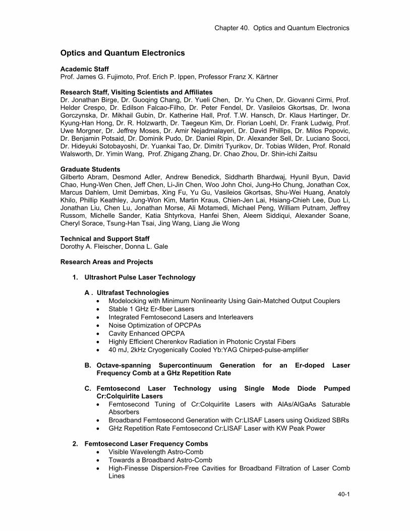
Mode-locking using the Kerr nonlinearity, also known as Kerr-lens mode-locking (KLM), is the key to generating ultrashort pulses in the few-cycle regime directly from laser oscillators. The KLM mechanism, which is an effective saturable absorber, leads to pulse shortening and counterbalances pulse lengthening caused by gain filtering experienced by the pulses. To minimize the gain-filtering effect, we have demonstrated a broadband dielectric output coupler (OC) for Ti:sapphire lasers with a reflectivity that matches the inverse shape of the gain medium, as shown in Fig. 1(a). With that OC we have achieved (1) much better beam quality with nearly no wavelength dependence across the octave-spanning range, (2) stronger resistance to environmental disturbances even when the cavity is directly exposed to free space, and (3) much lower mode-locking threshold (just above the continuous wave (cw) lasing threshold). As shown in Fig. 1(b), the key results of the laser performance are as follows: (1) We were able to initiate the mode-locking at 2.9 W of pump power when the cw output power is only 7 mW, which was just above the cw threshold of 2.85 W. (2) Once mode-locked, we could further decrease the pump power to 2.5 W and still generate a transform-limited output pulsewidth of <8 fs with > 100 mW power.
Fig. 1. (a) Gain profile of Ti:sapphire crystal (dashed black) and the designed transmission (solid red) and group delay (dashed blue) of gain-matched output coupler. (b) Intracavity and output pulsewidth at different pump power levels (left axis) and the corresponding output power (right axis). L.-Chen, M.Y. Sander, and F.X. Kärtner, “Kerr-lens Mode-locking with Minimum Nonlinearity Using Gain-Matched Output Couplers,” to be published in Opt Lett. 35 (2010)
• Stable 1GHz Er-fiber Lasers
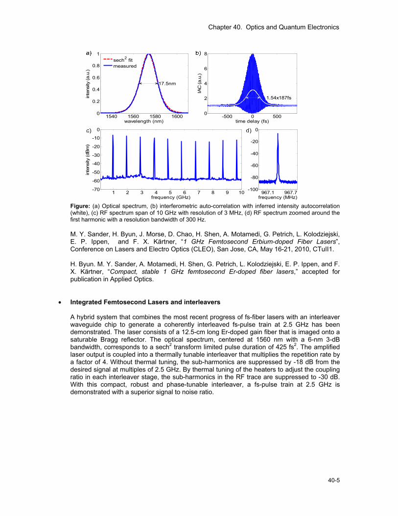
When scaling fundamentally mode-locked fiber lasers to higher repetition rates, a careful cavity design and good dispersion engineering are important in order to obtain femtosecond pulses while operating at reduced peak powers and smaller nonlinear phase shifts. On top of that, direct contact of the hot fiber core to the saturable Bragg reflector (SBR) introduces intense thermal heating. By splicing an 11-mm piece of standard single-mode fiber (SMF-28e) to a 97-mm Er gain fiber (Liekki Er80-8/125) thermal damage of the SBR, which in addition is protected by a pump-reflective coating, thermal heating can be avoided. We demonstrate a high-repetition-rate soliton fiber laser that is based on a highly-doped anomalously dispersive erbium-doped fiber. The laser generates 187-fs pulses at a repetition rate of 967 MHz with an average output power of 20.8 mW for a 10% output coupler.
Chapter 40. Optics and Quantum Electronics
40-5
967.1 967.7
-100
-80
-60
-40
-20
0
frequency (MHz)1 2 3 4 5 6 7 8 9 10-70
-60
-50
-40
-30
-20
-10
0
frequency (GHz)
inte
nsity
(dBm
)
1540 1560 1580 16000
0.2
0.4
0.6
0.8
1
wavelength (nm)
inte
nsity
(a.u
.)
17.5nm
sech2 fitmeasured
-500 0 5000
2
4
6
8
time delay (fs)
IAC
(a.u
.)
1.54x187fs
Figure: (a) Optical spectrum, (b) interferometric auto-correlation with inferred intensity autocorrelation (white), (c) RF spectrum span of 10 GHz with resolution of 3 MHz, (d) RF spectrum zoomed around the first harmonic with a resolution bandwidth of 300 Hz.
M. Y. Sander, H. Byun, J. Morse, D. Chao, H. Shen, A. Motamedi, G. Petrich, L. Kolodziejski, E. P. Ippen, and F. X. Kärtner, “1 GHz Femtosecond Erbium-doped Fiber Lasers”, Conference on Lasers and Electro Optics (CLEO), San Jose, CA, May 16-21, 2010, CTuII1. H. Byun. M. Y. Sander, A. Motamedi, H. Shen, G. Petrich, L. Kolodziejski, E. P. Ippen, and F. X. Kärtner, “Compact, stable 1 GHz femtosecond Er-doped fiber lasers,” accepted for publication in Applied Optics.
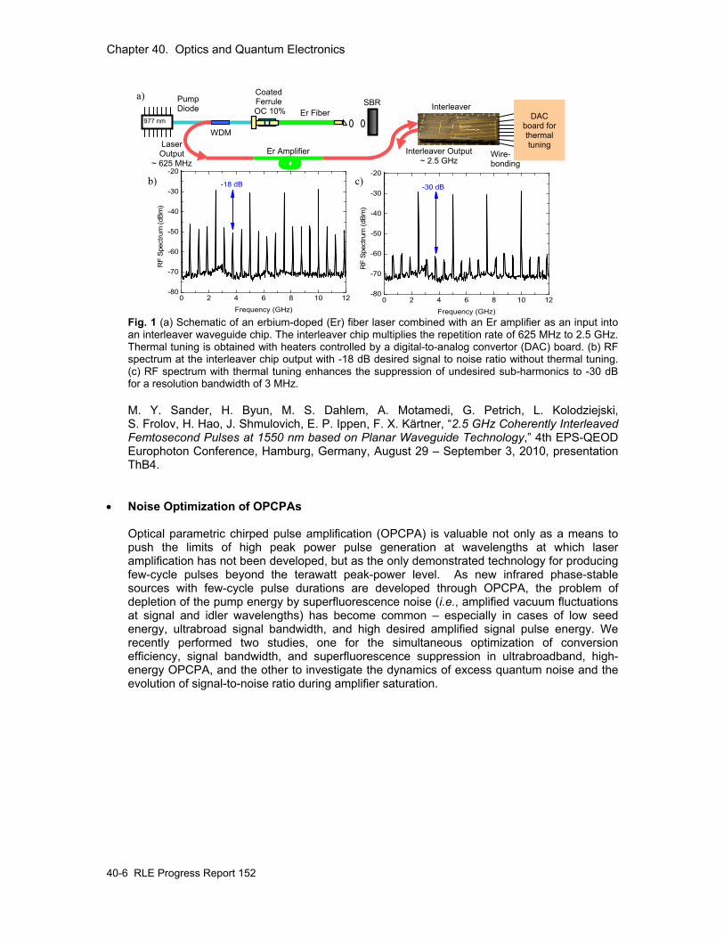
• Integrated Femtosecond Lasers and interleavers A hybrid system that combines the most recent progress of fs-fiber lasers with an interleaver waveguide chip to generate a coherently interleaved fs-pulse train at 2.5 GHz has been demonstrated. The laser consists of a 12.5-cm long Er-doped gain fiber that is imaged onto a saturable Bragg reflector. The optical spectrum, centered at 1560 nm with a 6-nm 3-dB bandwidth, corresponds to a sech2 transform limited pulse duration of 425 fs2. The amplified laser output is coupled into a thermally tunable interleaver that multiplies the repetition rate by a factor of 4. Without thermal tuning, the sub-harmonics are suppressed by -18 dB from the desired signal at multiples of 2.5 GHz. By thermal tuning of the heaters to adjust the coupling ratio in each interleaver stage, the sub-harmonics in the RF trace are suppressed to -30 dB. With this compact, robust and phase-tunable interleaver, a fs-pulse train at 2.5 GHz is demonstrated with a superior signal to noise ratio.
Chapter 40. Optics and Quantum Electronics
40-6 RLE Progress Report 152
Fig. 1 (a) Schematic of an erbium-doped (Er) fiber laser combined with an Er amplifier as an input into an interleaver waveguide chip. The interleaver chip multiplies the repetition rate of 625 MHz to 2.5 GHz. Thermal tuning is obtained with heaters controlled by a digital-to-analog convertor (DAC) board. (b) RF spectrum at the interleaver chip output with -18 dB desired signal to noise ratio without thermal tuning. (c) RF spectrum with thermal tuning enhances the suppression of undesired sub-harmonics to -30 dB for a resolution bandwidth of 3 MHz.
M. Y. Sander, H. Byun, M. S. Dahlem, A. Motamedi, G. Petrich, L. Kolodziejski, S. Frolov, H. Hao, J. Shmulovich, E. P. Ippen, F. X. Kärtner, “2.5 GHz Coherently Interleaved Femtosecond Pulses at 1550 nm based on Planar Waveguide Technology,” 4th EPS-QEOD Europhoton Conference, Hamburg, Germany, August 29 – September 3, 2010, presentation ThB4.
• Noise Optimization of OPCPAs Optical parametric chirped pulse amplification (OPCPA) is valuable not only as a means to push the limits of high peak power pulse generation at wavelengths at which laser amplification has not been developed, but as the only demonstrated technology for producing few-cycle pulses beyond the terawatt peak-power level. As new infrared phase-stable sources with few-cycle pulse durations are developed through OPCPA, the problem of depletion of the pump energy by superfluorescence noise (i.e., amplified vacuum fluctuations at signal and idler wavelengths) has become common – especially in cases of low seed energy, ultrabroad signal bandwidth, and high desired amplified signal pulse energy. We recently performed two studies, one for the simultaneous optimization of conversion efficiency, signal bandwidth, and superfluorescence suppression in ultrabroadband, high-energy OPCPA, and the other to investigate the dynamics of excess quantum noise and the evolution of signal-to-noise ratio during amplifier saturation.
SBRCoated Ferrule
OC 10%
Laser Output
~ 625 MHz
977 nm Er Fiber
Pump Diode
WDM
Er Amplifier Interleaver Output ~ 2.5 GHz
DAC
board for thermal tuning
Interleaver
Wire- bonding
b) c)
a)
0 2 4 6 8 10 12-80
-70
-60
-50
-40
-30
-20
R
F S
pect
rum
(dB
m)
Frequency (GHz)
-18 dB
0 2 4 6 8 10 12-80
-70
-60
-50
-40
-30
-20
-30 dB
RF
Spec
trum
(dBm
)
Frequency (GHz)
Chapter 40. Optics and Quantum Electronics
40-7
0 1 2 3 4
100
200
300
400
500
600
700 Low Chirp Optimum Chirp High Chirp
Sign
al-to
-Noi
se ra
tioCrystal Depth (mm)
0 1 2 3 4
10-2
100
102
104
Std. Deviation Signal Idler
Ener
gy (r
el. u
n.)
Crystal Depth (mm)
Average
Low chirp regime
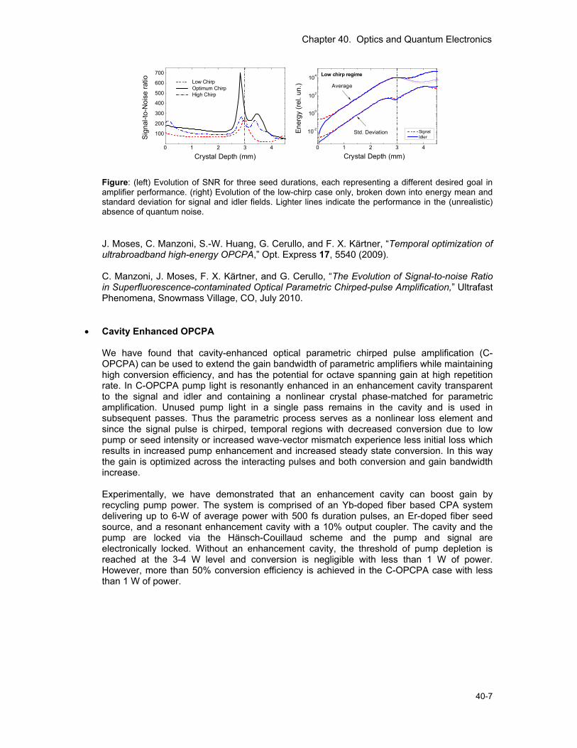
Figure: (left) Evolution of SNR for three seed durations, each representing a different desired goal in amplifier performance. (right) Evolution of the low-chirp case only, broken down into energy mean and standard deviation for signal and idler fields. Lighter lines indicate the performance in the (unrealistic) absence of quantum noise.
J. Moses, C. Manzoni, S.-W. Huang, G. Cerullo, and F. X. Kärtner, “Temporal optimization of ultrabroadband high-energy OPCPA,” Opt. Express 17, 5540 (2009).
C. Manzoni, J. Moses, F. X. Kärtner, and G. Cerullo, “The Evolution of Signal-to-noise Ratio in Superfluorescence-contaminated Optical Parametric Chirped-pulse Amplification,” Ultrafast Phenomena, Snowmass Village, CO, July 2010.
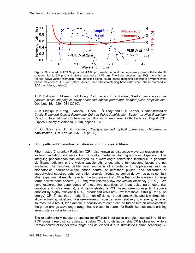
• Cavity Enhanced OPCPA We have found that cavity-enhanced optical parametric chirped pulse amplification (C-OPCPA) can be used to extend the gain bandwidth of parametric amplifiers while maintaining high conversion efficiency, and has the potential for octave spanning gain at high repetition rate. In C-OPCPA pump light is resonantly enhanced in an enhancement cavity transparent to the signal and idler and containing a nonlinear crystal phase-matched for parametric amplification. Unused pump light in a single pass remains in the cavity and is used in subsequent passes. Thus the parametric process serves as a nonlinear loss element and since the signal pulse is chirped, temporal regions with decreased conversion due to low pump or seed intensity or increased wave-vector mismatch experience less initial loss which results in increased pump enhancement and increased steady state conversion. In this way the gain is optimized across the interacting pulses and both conversion and gain bandwidth increase. Experimentally, we have demonstrated that an enhancement cavity can boost gain by recycling pump power. The system is comprised of an Yb-doped fiber based CPA system delivering up to 6-W of average power with 500 fs duration pulses, an Er-doped fiber seed source, and a resonant enhancement cavity with a 10% output coupler. The cavity and the pump are locked via the Hänsch-Couillaud scheme and the pump and signal are electronically locked. Without an enhancement cavity, the threshold of pump depletion is reached at the 3-4 W level and conversion is negligible with less than 1 W of power. However, more than 50% conversion efficiency is achieved in the C-OPCPA case with less than 1 W of power.
Chapter 40. Optics and Quantum Electronics
40-8 RLE Progress Report 152
Figure: Simulated C-OPCPA, pumped at 1.03 µm, seeded around the degeneracy point with bandwidth covering 1.4 to 3.5 µm, and phase matched at 1.55 µm. The input coupler has 10% transmission. Plotted: wave-vector mismatch (red), amplified signal (blue), phase-matching bandwidth (PMBW) when phase matched at 1.55 µm (black, dotted), and phase-matching bandwidth when phase matched at 2.06 µm (black, dashed). A. M. Siddiqui, J. Moses, K.-H. Hong, C.-J. Lai, and F. X. Kärtner, “Performance scaling via passive pulse shaping in cavity-enhanced optical parametric chirped-pulse amplification,” Opt. Lett. 35, 1929-1931 (2010).
A. M. Siddiqui, K. Hong, J. Moses, J. Chen, F. Ö. Ilday, and F. X. Kärtner, ”Demonstration of Cavity-Enhanced Optical Parametric Chirped-Pulse Amplification System at High Repetition Rate,” in International Conference on Ultrafast Phenomena, OSA Technical Digest (CD) (Optical Society of America, 2010), paper TuC1. F. Ö. Ilday and F. X. Kärtner, “Cavity-enhanced optical parametric chirped-pulse amplification,” Opt. Lett. 31, 637-639 (2006).
• Highly efficient Cherenkov radiation in photonic crystal fibers
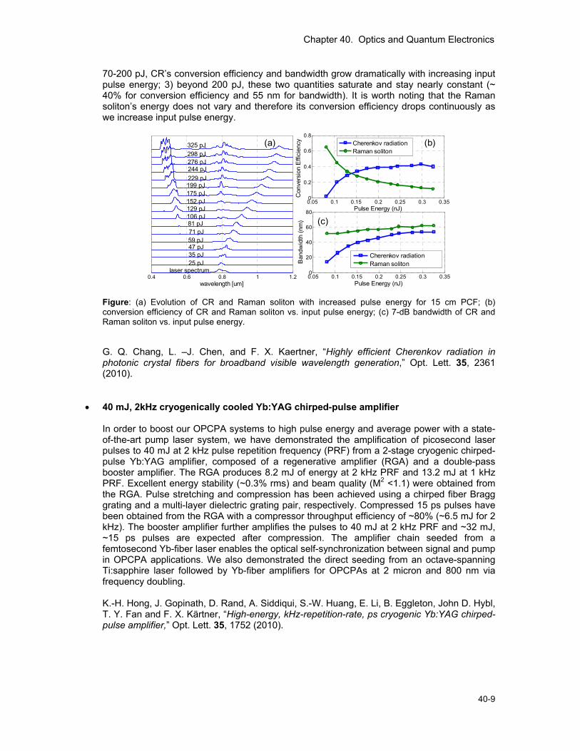
Fiber-hosted Cherenkov Radiation (CR), also known as dispersive wave generation or non-solitonic radiation, originates from a soliton perturbed by higher-order dispersion. This intriguing phenomenon has emerged as a wavelength conversion technique to generate significant radiation in the visible wavelength range, where femtosecond lasers are not available. The resultant visible laser source is of importance for applications such as biophotonics, carrier-envelope phase control of ultrashort pulses, and calibration of astrophysical spectrographs using high-precision frequency combs (known as astro-combs). Most experimental results have left the impression that CR in the visible wavelength range forms narrow-band spectra (~10 nm) with relatively low conversion efficiency (~10%). We have explored the dependence of these two quantities on input pulse parameters (i.e. duration and pulse energy), and demonstrated a PCF based green-orange light source enabled by highly efficient (>40%), broadband (>50 nm), low threshold (<100 pJ for pulse energy) CR. These three merits (i.e. high efficiency, broad bandwidth, and low threshold) allow achieving wideband visible-wavelength spectra from relatively low energy ultrafast sources. As a result, for example, a near-IR astro-comb can be turned into an astro-comb in the green-orange wavelength range that is pivotal to search for Earth-like exoplanets orbiting around stars similar to the sun. The experimentally measured spectra for different input pulse energies coupled into 15 cm PCF reveal three distinct regimes: 1) below 70 pJ, no distinguishable CR is observed while a Raman soliton at longer wavelength has developed due to stimulated Raman scattering; 2)
Chapter 40. Optics and Quantum Electronics
40-9
70-200 pJ, CR’s conversion efficiency and bandwidth grow dramatically with increasing input pulse energy; 3) beyond 200 pJ, these two quantities saturate and stay nearly constant (~ 40% for conversion efficiency and 55 nm for bandwidth). It is worth noting that the Raman soliton’s energy does not vary and therefore its conversion efficiency drops continuously as we increase input pulse energy.
Figure: (a) Evolution of CR and Raman soliton with increased pulse energy for 15 cm PCF; (b) conversion efficiency of CR and Raman soliton vs. input pulse energy; (c) 7-dB bandwidth of CR and Raman soliton vs. input pulse energy.
G. Q. Chang, L. –J. Chen, and F. X. Kaertner, “Highly efficient Cherenkov radiation in photonic crystal fibers for broadband visible wavelength generation,” Opt. Lett. 35, 2361 (2010).
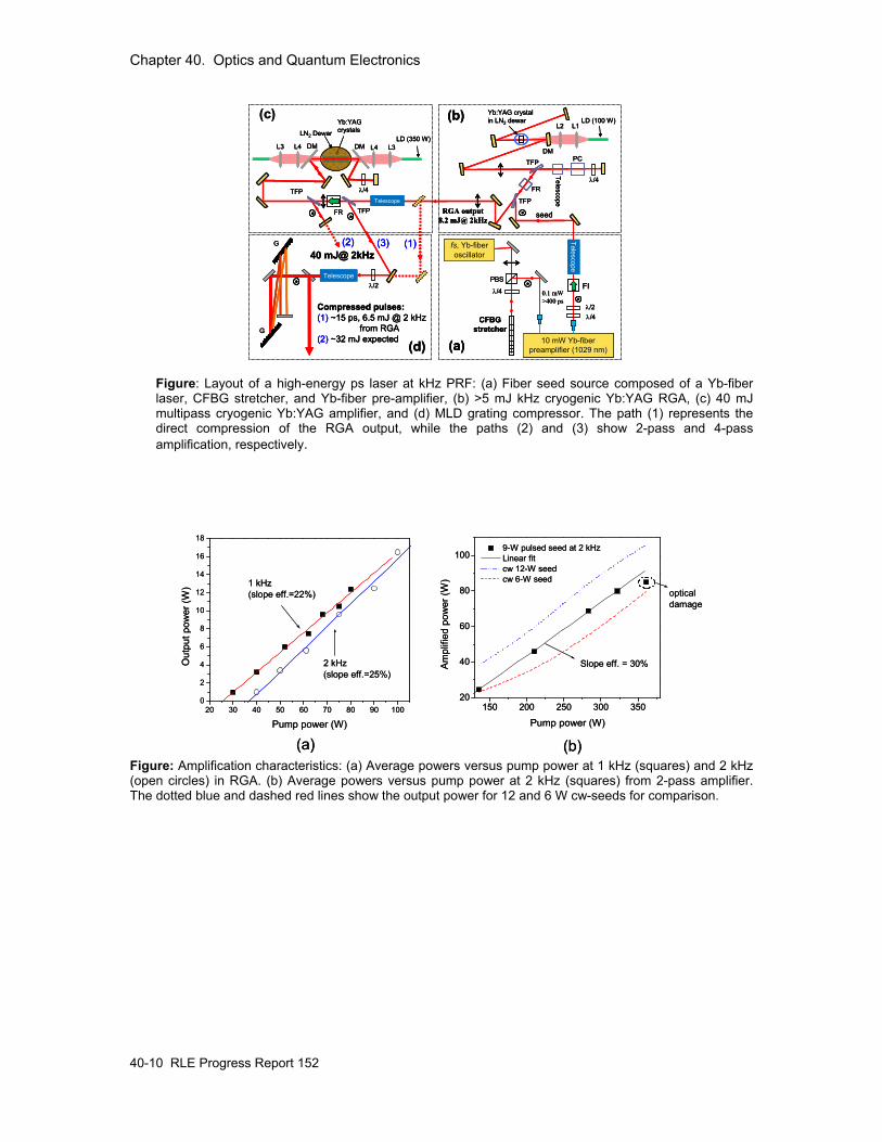
• 40 mJ, 2kHz cryogenically cooled Yb:YAG chirped-pulse amplifier In order to boost our OPCPA systems to high pulse energy and average power with a state-of-the-art pump laser system, we have demonstrated the amplification of picosecond laser pulses to 40 mJ at 2 kHz pulse repetition frequency (PRF) from a 2-stage cryogenic chirped-pulse Yb:YAG amplifier, composed of a regenerative amplifier (RGA) and a double-pass booster amplifier. The RGA produces 8.2 mJ of energy at 2 kHz PRF and 13.2 mJ at 1 kHz PRF. Excellent energy stability (~0.3% rms) and beam quality (M2 <1.1) were obtained from the RGA. Pulse stretching and compression has been achieved using a chirped fiber Bragg grating and a multi-layer dielectric grating pair, respectively. Compressed 15 ps pulses have been obtained from the RGA with a compressor throughput efficiency of ~80% (~6.5 mJ for 2 kHz). The booster amplifier further amplifies the pulses to 40 mJ at 2 kHz PRF and ~32 mJ, ~15 ps pulses are expected after compression. The amplifier chain seeded from a femtosecond Yb-fiber laser enables the optical self-synchronization between signal and pump in OPCPA applications. We also demonstrated the direct seeding from an octave-spanning Ti:sapphire laser followed by Yb-fiber amplifiers for OPCPAs at 2 micron and 800 nm via frequency doubling.
K.-H. Hong, J. Gopinath, D. Rand, A. Siddiqui, S.-W. Huang, E. Li, B. Eggleton, John D. Hybl, T. Y. Fan and F. X. Kärtner, “High-energy, kHz-repetition-rate, ps cryogenic Yb:YAG chirped-pulse amplifier,” Opt. Lett. 35, 1752 (2010).
0.4 0.6 0.8 1 1.2wavelength [um]
laser spectrum25 pJ35 pJ47 pJ59 pJ71 pJ81 pJ106 pJ129 pJ152 pJ175 pJ199 pJ229 pJ244 pJ276 pJ298 pJ325 pJ (a)
0.05 0.1 0.15 0.2 0.25 0.3 0.350
0.2
0.4
0.6
0.8
Pulse Energy (nJ)
Con
vers
ion
Effi
cien
cy
Cherenkov radiationRaman soliton
(b)
0.05 0.1 0.15 0.2 0.25 0.3 0.350
20
40
60
80
Pulse Energy (nJ)
Ban
dwid
th (n
m)
Cherenkov radiationRaman soliton
(c)
Chapter 40. Optics and Quantum Electronics
40-10 RLE Progress Report 152
(c)
fs, Yb-fiber oscillator
CFBG stretcher
λ/4
PBS
0.1 mW>400 ps
λ/4λ/2
FI
Telescope
10 mW Yb-fiber preamplifier (1029 nm)
LD (100 W)Yb:YAG crystal in LN2 dewar
PCTFP
(b)
TFP
FR
seedRGA output8.2 mJ@ 2kHz
λ/4
Telescope
(a)
40 mJ@ 2kHz
Telescope
Compressed pulses:(1) ~15 ps, 6.5 mJ @ 2 kHz
from RGA(2) ~32 mJ expected (d)
LN2 Dewar
Yb:YAGcrystals
LD (350 W)DM
λ/4
DML3 L4 L4 L3
TelescopeTFP
TFP
G
G
FR
(1)(2) (3)
L2 L1
DM
λ/2
Figure: Layout of a high-energy ps laser at kHz PRF: (a) Fiber seed source composed of a Yb-fiber laser, CFBG stretcher, and Yb-fiber pre-amplifier, (b) >5 mJ kHz cryogenic Yb:YAG RGA, (c) 40 mJ multipass cryogenic Yb:YAG amplifier, and (d) MLD grating compressor. The path (1) represents the direct compression of the RGA output, while the paths (2) and (3) show 2-pass and 4-pass amplification, respectively.
20 30 40 50 60 70 80 90 1000
2
4
6
8
10
12
14
16
18
1 kHz(slope eff.=22%)
2 kHz(slope eff.=25%)
Out
put p
ower
(W)
Pump power (W)
(a) (b)
150 200 250 300 35020
40
60
80
100
Slope eff. = 30%
optical damage
9-W pulsed seed at 2 kHz Linear fit cw 12-W seed cw 6-W seed
Am
plifi
ed p
ower
(W)
Pump power (W)20 30 40 50 60 70 80 90 100
0
2
4
6
8
10
12
14
16
18
1 kHz(slope eff.=22%)
2 kHz(slope eff.=25%)
Out
put p
ower
(W)
Pump power (W)
(a) (b)
150 200 250 300 35020
40
60
80
100
Slope eff. = 30%
optical damage
9-W pulsed seed at 2 kHz Linear fit cw 12-W seed cw 6-W seed
Am
plifi
ed p
ower
(W)
Pump power (W)
Figure: Amplification characteristics: (a) Average powers versus pump power at 1 kHz (squares) and 2 kHz (open circles) in RGA. (b) Average powers versus pump power at 2 kHz (squares) from 2-pass amplifier. The dotted blue and dashed red lines show the output power for 12 and 6 W cw-seeds for comparison.
Chapter 40. Optics and Quantum Electronics
40-11
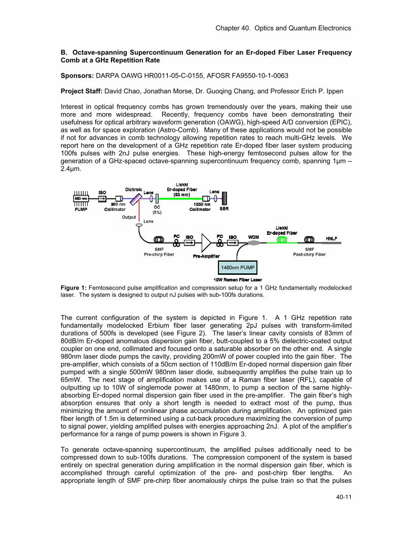
B. Octave-spanning Supercontinuum Generation for an Er-doped Fiber Laser Frequency Comb at a GHz Repetition Rate Sponsors: DARPA OAWG HR0011-05-C-0155, AFOSR FA9550-10-1-0063 Project Staff: David Chao, Jonathan Morse, Dr. Guoqing Chang, and Professor Erich P. Ippen Interest in optical frequency combs has grown tremendously over the years, making their use more and more widespread. Recently, frequency combs have been demonstrating their usefulness for optical arbitrary waveform generation (OAWG), high-speed A/D conversion (EPIC), as well as for space exploration (Astro-Comb). Many of these applications would not be possible if not for advances in comb technology allowing repetition rates to reach multi-GHz levels. We report here on the development of a GHz repetition rate Er-doped fiber laser system producing 100fs pulses with 2nJ pulse energies. These high-energy femtosecond pulses allow for the generation of a GHz-spaced octave-spanning supercontinuum frequency comb, spanning 1µm – 2.4µm.
Figure 1: Femtosecond pulse amplification and compression setup for a 1 GHz fundamentally modelocked laser. The system is designed to output nJ pulses with sub-100fs durations. The current configuration of the system is depicted in Figure 1. A 1 GHz repetition rate fundamentally modelocked Erbium fiber laser generating 2pJ pulses with transform-limited durations of 500fs is developed (see Figure 2). The laser’s linear cavity consists of 83mm of 80dB/m Er-doped anomalous dispersion gain fiber, butt-coupled to a 5% dielectric-coated output coupler on one end, collimated and focused onto a saturable absorber on the other end. A single 980nm laser diode pumps the cavity, providing 200mW of power coupled into the gain fiber. The pre-amplifier, which consists of a 50cm section of 110dB/m Er-doped normal dispersion gain fiber pumped with a single 500mW 980nm laser diode, subsequently amplifies the pulse train up to 65mW. The next stage of amplification makes use of a Raman fiber laser (RFL), capable of outputting up to 10W of singlemode power at 1480nm, to pump a section of the same highly-absorbing Er-doped normal dispersion gain fiber used in the pre-amplifier. The gain fiber’s high absorption ensures that only a short length is needed to extract most of the pump, thus minimizing the amount of nonlinear phase accumulation during amplification. An optimized gain fiber length of 1.5m is determined using a cut-back procedure maximizing the conversion of pump to signal power, yielding amplified pulses with energies approaching 2nJ. A plot of the amplifier’s performance for a range of pump powers is shown in Figure 3. To generate octave-spanning supercontinuum, the amplified pulses additionally need to be compressed down to sub-100fs durations. The compression component of the system is based entirely on spectral generation during amplification in the normal dispersion gain fiber, which is accomplished through careful optimization of the pre- and post-chirp fiber lengths. An appropriate length of SMF pre-chirp fiber anomalously chirps the pulse train so that the pulses
Chapter 40. Optics and Quantum Electronics
40-12 RLE Progress Report 152
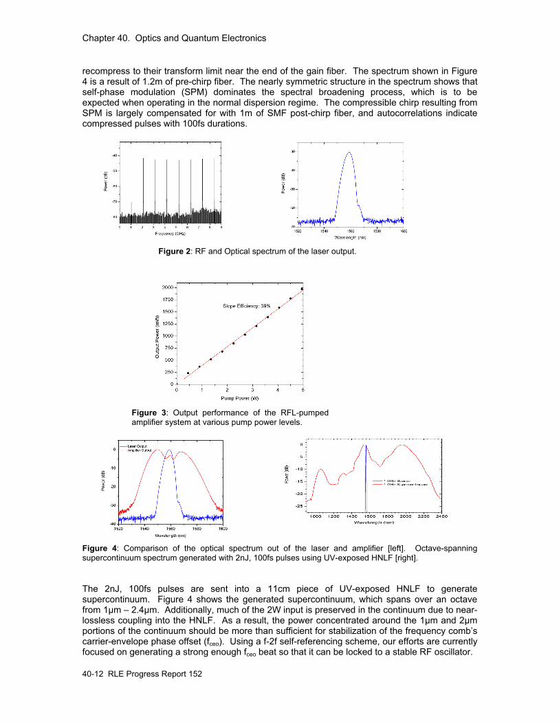
recompress to their transform limit near the end of the gain fiber. The spectrum shown in Figure 4 is a result of 1.2m of pre-chirp fiber. The nearly symmetric structure in the spectrum shows that self-phase modulation (SPM) dominates the spectral broadening process, which is to be expected when operating in the normal dispersion regime. The compressible chirp resulting from SPM is largely compensated for with 1m of SMF post-chirp fiber, and autocorrelations indicate compressed pulses with 100fs durations.
Figure 2: RF and Optical spectrum of the laser output.
Figure 3: Output performance of the RFL-pumped amplifier system at various pump power levels.
Figure 4: Comparison of the optical spectrum out of the laser and amplifier [left]. Octave-spanning supercontinuum spectrum generated with 2nJ, 100fs pulses using UV-exposed HNLF [right]. The 2nJ, 100fs pulses are sent into a 11cm piece of UV-exposed HNLF to generate supercontinuum. Figure 4 shows the generated supercontinuum, which spans over an octave from 1µm – 2.4µm. Additionally, much of the 2W input is preserved in the continuum due to near-lossless coupling into the HNLF. As a result, the power concentrated around the 1µm and 2µm portions of the continuum should be more than sufficient for stabilization of the frequency comb’s carrier-envelope phase offset (fceo). Using a f-2f self-referencing scheme, our efforts are currently focused on generating a strong enough fceo beat so that it can be locked to a stable RF oscillator.
Chapter 40. Optics and Quantum Electronics
40-13
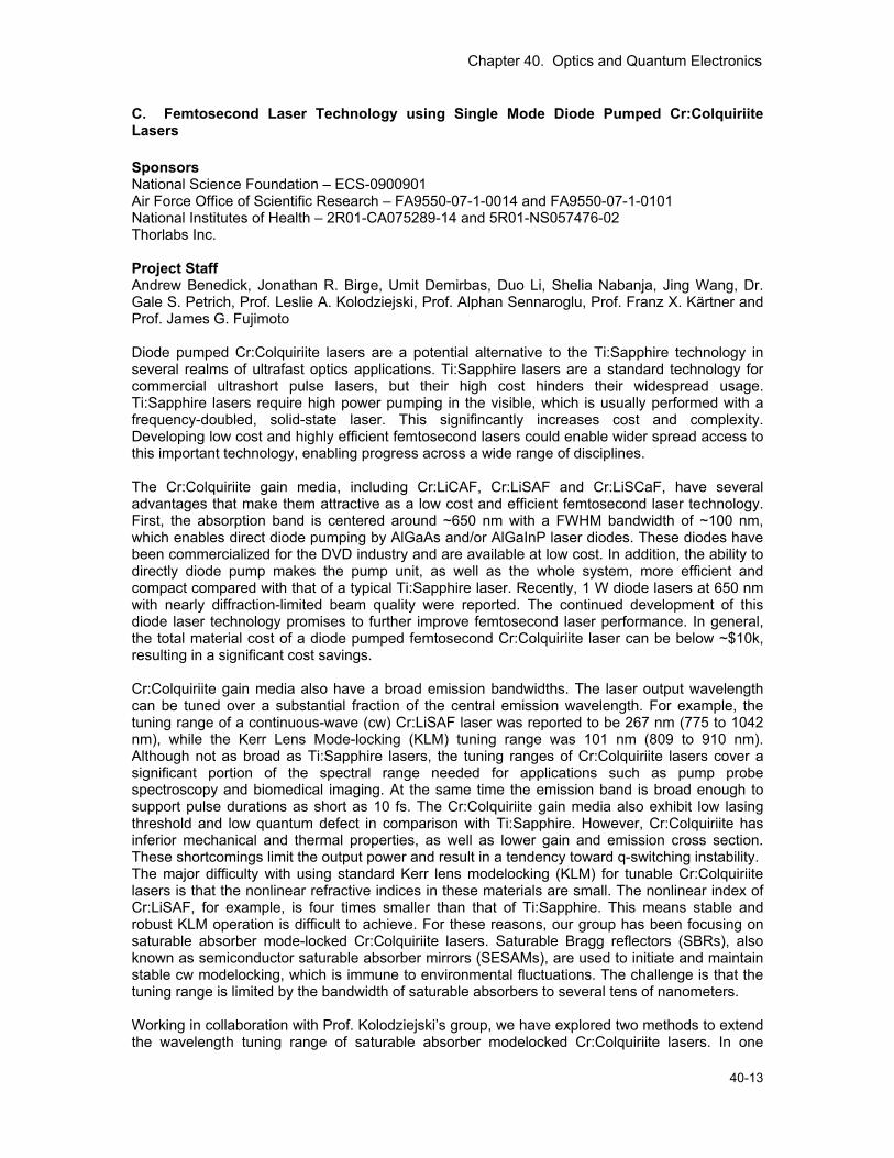
C. Femtosecond Laser Technology using Single Mode Diode Pumped Cr:Colquiriite Lasers Sponsors National Science Foundation – ECS-0900901 Air Force Office of Scientific Research – FA9550-07-1-0014 and FA9550-07-1-0101 National Institutes of Health – 2R01-CA075289-14 and 5R01-NS057476-02 Thorlabs Inc. Project Staff Andrew Benedick, Jonathan R. Birge, Umit Demirbas, Duo Li, Shelia Nabanja, Jing Wang, Dr. Gale S. Petrich, Prof. Leslie A. Kolodziejski, Prof. Alphan Sennaroglu, Prof. Franz X. Kärtner and Prof. James G. Fujimoto Diode pumped Cr:Colquiriite lasers are a potential alternative to the Ti:Sapphire technology in several realms of ultrafast optics applications. Ti:Sapphire lasers are a standard technology for commercial ultrashort pulse lasers, but their high cost hinders their widespread usage. Ti:Sapphire lasers require high power pumping in the visible, which is usually performed with a frequency-doubled, solid-state laser. This signifincantly increases cost and complexity. Developing low cost and highly efficient femtosecond lasers could enable wider spread access to this important technology, enabling progress across a wide range of disciplines. The Cr:Colquiriite gain media, including Cr:LiCAF, Cr:LiSAF and Cr:LiSCaF, have several advantages that make them attractive as a low cost and efficient femtosecond laser technology. First, the absorption band is centered around ~650 nm with a FWHM bandwidth of ~100 nm, which enables direct diode pumping by AlGaAs and/or AlGaInP laser diodes. These diodes have been commercialized for the DVD industry and are available at low cost. In addition, the ability to directly diode pump makes the pump unit, as well as the whole system, more efficient and compact compared with that of a typical Ti:Sapphire laser. Recently, 1 W diode lasers at 650 nm with nearly diffraction-limited beam quality were reported. The continued development of this diode laser technology promises to further improve femtosecond laser performance. In general, the total material cost of a diode pumped femtosecond Cr:Colquiriite laser can be below ~$10k, resulting in a significant cost savings. Cr:Colquiriite gain media also have a broad emission bandwidths. The laser output wavelength can be tuned over a substantial fraction of the central emission wavelength. For example, the tuning range of a continuous-wave (cw) Cr:LiSAF laser was reported to be 267 nm (775 to 1042 nm), while the Kerr Lens Mode-locking (KLM) tuning range was 101 nm (809 to 910 nm). Although not as broad as Ti:Sapphire lasers, the tuning ranges of Cr:Colquiriite lasers cover a significant portion of the spectral range needed for applications such as pump probe spectroscopy and biomedical imaging. At the same time the emission band is broad enough to support pulse durations as short as 10 fs. The Cr:Colquiriite gain media also exhibit low lasing threshold and low quantum defect in comparison with Ti:Sapphire. However, Cr:Colquiriite has inferior mechanical and thermal properties, as well as lower gain and emission cross section. These shortcomings limit the output power and result in a tendency toward q-switching instability. The major difficulty with using standard Kerr lens modelocking (KLM) for tunable Cr:Colquiriite lasers is that the nonlinear refractive indices in these materials are small. The nonlinear index of Cr:LiSAF, for example, is four times smaller than that of Ti:Sapphire. This means stable and robust KLM operation is difficult to achieve. For these reasons, our group has been focusing on saturable absorber mode-locked Cr:Colquiriite lasers. Saturable Bragg reflectors (SBRs), also known as semiconductor saturable absorber mirrors (SESAMs), are used to initiate and maintain stable cw modelocking, which is immune to environmental fluctuations. The challenge is that the tuning range is limited by the bandwidth of saturable absorbers to several tens of nanometers. Working in collaboration with Prof. Kolodziejski’s group, we have explored two methods to extend the wavelength tuning range of saturable absorber modelocked Cr:Colquiriite lasers. In one
Chapter 40. Optics and Quantum Electronics
40-14 RLE Progress Report 152
approach, a large tuning range is divided into narrower wavelength regions and an SBR is designed and grown to enable continuous tuning around a center wavelength in each wavelength region. We have demonstrated continuous cw modelocked tuning using SBRs with center wavelengths at 800 nm, 850 nm and 910 nm. The overall tuning range extends from 803 nm to 923 nm with Cr:LiSAF. In a second approach, we designed and fabricated a broadband 910 nm SBR to achieve continuous cw modelocked tuning from 800 nm to 905 nm in a Cr:LiSAF laser. The mirror bandwidth is increased by oxidizing the AlAs layers into AlxOy layers, which results in a larger refractive index contrast between adjacent layers in the Bragg stack. The 105 nm tuning range is, to our knowledge, the broadest reported for saturable absorber modelocked femtosecond solid state lasers. The design and development of high repetition rate Cr:LiSAF lasers is important for timing jitter, microwave synthesis and timing distribution applications. Although the quantum limited timing jitter noise grows with increasing repetition rate, compact systems enable engineering methods which can isolate the lasers from environmental fluctuations, so that the measured timing jitter noise may approach the quantum limit. However, reducing the cavity length brings several challenges and requires considering dispersion compensation, saturable absorber design and heat sinking. We experimentally demonstrated a 1-GHz repetition rate cw modelocked Cr:LiSAF laser with 55 fs pulse duration and 1.8 kW peak power. This result represents a significant improvement over the previous high repetition rate Cr:LiSAF lasers. This projects is ongoing and we will measure the timing jitter noise from these 1 GHz lasers as well as design and develop even higher repetition rate Cr:LiSAF lasers. Recent accomplishments: • Femtosecond Tuning of Cr:Colquiriite Lasers with AlAs/AlGaAs Saturable Absorbers
Broadly wavelength tunable mode-locked lasers are important for applications such as multiphoton microscopy or pump probe spectroscopy. Mode-locked Ti:Sapphire lasers are widely used in ultrafast optics and can provide ∼100-fs long pulses, with 100s of kw peak powers and broad wavelength tunability from 680 to 1080 nm. However the primary disadvantage of Ti:Sapphire lasers is that they require frequency doubled Nd:YAG laser pumping, increasing cost and complexity. Cr:Colquiriite lasers can be directly diode pumped and are a low-lost and efficient alternative to Ti:Sapphire technology for many applications. Among Cr:Colquiriites, Cr:LiSAF has the broadest gain, and in continuous-wave (cw) operation, its tuning range extends from 775 nm to 1042 nm [1]. Cr:LiCAF has also received considerable attention due to its blue shifted emission spectrum, which enables cw tuning from 754 nm to 871 nm [1]. Using Kerr-lens mode-locking (KLM) with Cr:LiSAF lasers, femtosecond tuning ranges of 835 nm to 910 nm [2], and 809 nm to 910 nm [3] have been demonstrated. However, because Cr:LiSAF has a small nonlinear index, KLM is difficult and suffers from instability and relatively low efficiency. In order to address this problem Cr:Colquiriite lasers can be modelocked by semiconductor saturable Bragg reflectors (SBRs), also referred as saturable absorber mirrors (SESAMs). The modelocking is self-starting and robust. In this report, we present femtosecond tuning results in Cr:LiSAF and Cr:LiCAF lasers. Using a combination of SBRs designed with central wavelengths at 800 nm, 850 nm and 910 nm and an intracavity birefringent tuning plate, an overall tuning range of 828-923 nm was obtained with sub-200-fs pulses and ~nJ pulse energy in Cr:LiSAF. In Cr:LiCAF using an 800 nm SBR, a mode-locked tuning range of 767-817 nm with average pulsewidths of ∼133-fs and average pulse energies of 1.48 nJ was obtained. To our knowledge, these are the first reported detailed femtosecond tuning results in Cr:LiCAF and first femtosecond tuning results in Cr:LiSAF around 800 and 900 nm.
Chapter 40. Optics and Quantum Electronics
40-15
PBS
Cr:LiSAFD1, TM640 nm
M1DCM
75 mm
M2DCM
75 mmf=65 mm
M5DCM
100 mm3% OC
f=65 mm
PBS
D3, TM640 nm
D4, TE
640 nm
M3DCM
M4DCM
850 nm SESAM/SBR
BR tuning plate
D2, TE
640 nm
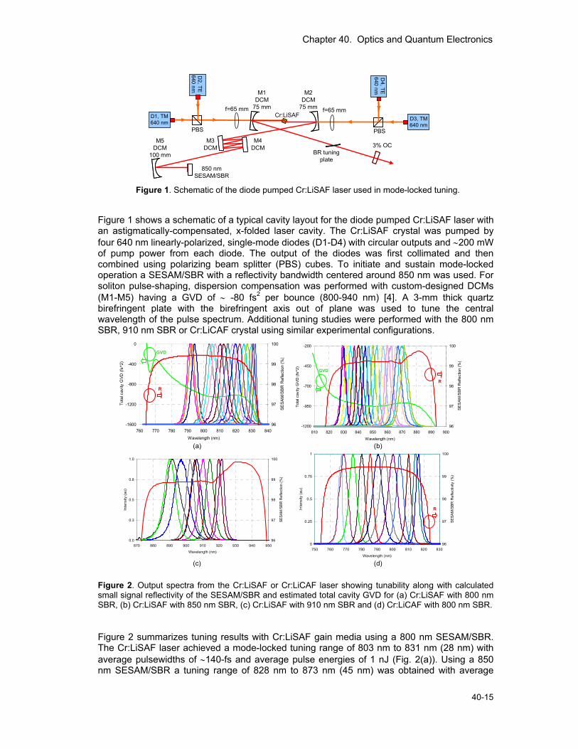
Figure 1. Schematic of the diode pumped Cr:LiSAF laser used in mode-locked tuning.
Figure 1 shows a schematic of a typical cavity layout for the diode pumped Cr:LiSAF laser with an astigmatically-compensated, x-folded laser cavity. The Cr:LiSAF crystal was pumped by four 640 nm linearly-polarized, single-mode diodes (D1-D4) with circular outputs and ∼200 mW of pump power from each diode. The output of the diodes was first collimated and then combined using polarizing beam splitter (PBS) cubes. To initiate and sustain mode-locked operation a SESAM/SBR with a reflectivity bandwidth centered around 850 nm was used. For soliton pulse-shaping, dispersion compensation was performed with custom-designed DCMs (M1-M5) having a GVD of ∼ -80 fs2 per bounce (800-940 nm) [4]. A 3-mm thick quartz birefringent plate with the birefringent axis out of plane was used to tune the central wavelength of the pulse spectrum. Additional tuning studies were performed with the 800 nm SBR, 910 nm SBR or Cr:LiCAF crystal using similar experimental configurations.
0
0.25
0.5
0.75
1
750 760 770 780 790 800 810 820 830
Wavelength (nm)
Inte
nsity
(au)
96
97
98
99
100SE
SAM
/SBR
Ref
lect
ivity
(%)
R
0.0
0.3
0.5
0.8
1.0
870 880 890 900 910 920 930 940 950
Wavelength (nm)
Inte
nsity
(au)
96
97
98
99
100
SESA
M/S
BR R
efle
ctio
n (%
)
-1200
-950
-700
-450
-200
810 820 830 840 850 860 870 880 890 900
Wavelength (nm)
Tota
l cav
ity G
VD (f
s^2)
_
96
97
98
99
100
SES
AM/S
BR R
efle
ctio
n (%
)
R
GVD
-1600
-1200
-800
-400
0
760 770 780 790 800 810 820 830 840
Wavelength (nm)
Tota
l cav
ity G
VD (f
s^2)
_
96
97
98
99
100
SES
AM/S
BR
Ref
lect
ion
(%)
GVD
R
(a) (b)
(c) (d)
Figure 2. Output spectra from the Cr:LiSAF or Cr:LiCAF laser showing tunability along with calculated small signal reflectivity of the SESAM/SBR and estimated total cavity GVD for (a) Cr:LiSAF with 800 nm SBR, (b) Cr:LiSAF with 850 nm SBR, (c) Cr:LiSAF with 910 nm SBR and (d) Cr:LiCAF with 800 nm SBR. Figure 2 summarizes tuning results with Cr:LiSAF gain media using a 800 nm SESAM/SBR. The Cr:LiSAF laser achieved a mode-locked tuning range of 803 nm to 831 nm (28 nm) with average pulsewidths of ∼140-fs and average pulse energies of 1 nJ (Fig. 2(a)). Using a 850 nm SESAM/SBR a tuning range of 828 nm to 873 nm (45 nm) was obtained with average
Chapter 40. Optics and Quantum Electronics
40-16 RLE Progress Report 152
pulsewidths of ∼190-fs and average pulse energies of 1.87 nJ (Fig. 2(b)). A 910 nm SESAM/SBR was also used with Cr:LiSAF to obtain a tuning range from 890 nm to 923 nm (Fig. 2(c)). With Cr:LiCAF gain medium a mode-locked tuning range of 767 nm to 817 nm (50 nm) with average pulsewidths of ∼133-fs and average pulse energies of 1.48 nJ was obtained (Fig. 2(d)). Pulses as short as 26 fs with Cr:LiSAF and 39 fs with Cr:LiCAF have also been achieved, which is to our knowledge, the shortest pulse durations reported from SESAM/SBR mode-locked Cr:Colquiriite lasers.
• Broadband Femtosecond Generation with Cr: LiSAF Lasers using Oxidized SBRs Broadband of femtosecond lasers is important for many applications in ultrafast optics. In continuous-wave (cw) operation, Cr:LiSAF has been demonstrated to tune from 775 nm to 1042 nm [1]; whereas for mode-locked operation, tuning ranges from 809 nm to 910 nm [2] and 835 nm to 910 nm [3] have been demonstrated using Kerr-lens mode-locking (KLM). However, due to the small nonlinear refractive index of Cr:LiSAF, long-term stable and robust KLM operation is difficult to achieve. Compared with KLM, mode-locking initiated by saturable Bragg reflectors (SBRs) is self-starting and immune to environmental fluctuations. However, the reflection bandwidth of typical SBRs is limited by the low-index contrast (Δn∼0.5-0.6) between AlGaAs/AlAs Bragg layers, which in turn restricts the tuning range of SBR mode-locked Cr:LiSAF lasers to ~50 nm [1, 4]. In this report, we present a broadly tunable, low-cost, diode-pumped Cr:LiSAF laser mode-locked using a broadband oxidized SBR which can be tuned from 800 nm to 905 nm.
PBS
Cr:LiSAFD1, TM640 nm
M1DCM
75 mm
M2DCM
75 mmf=65 mm
M5DCM
150 mm3% OC
D2, TE660 nm
D3, TE
640 nm
Dichroic filter
f=65 mm
PBS
D4, TM640 nm
D6, TE
640 nm
D5, TE660 nm
M3DCM M4
DCMHR(cw)
Oxidized/BroadbandSBR
BR tuning plate
Dichroic filter
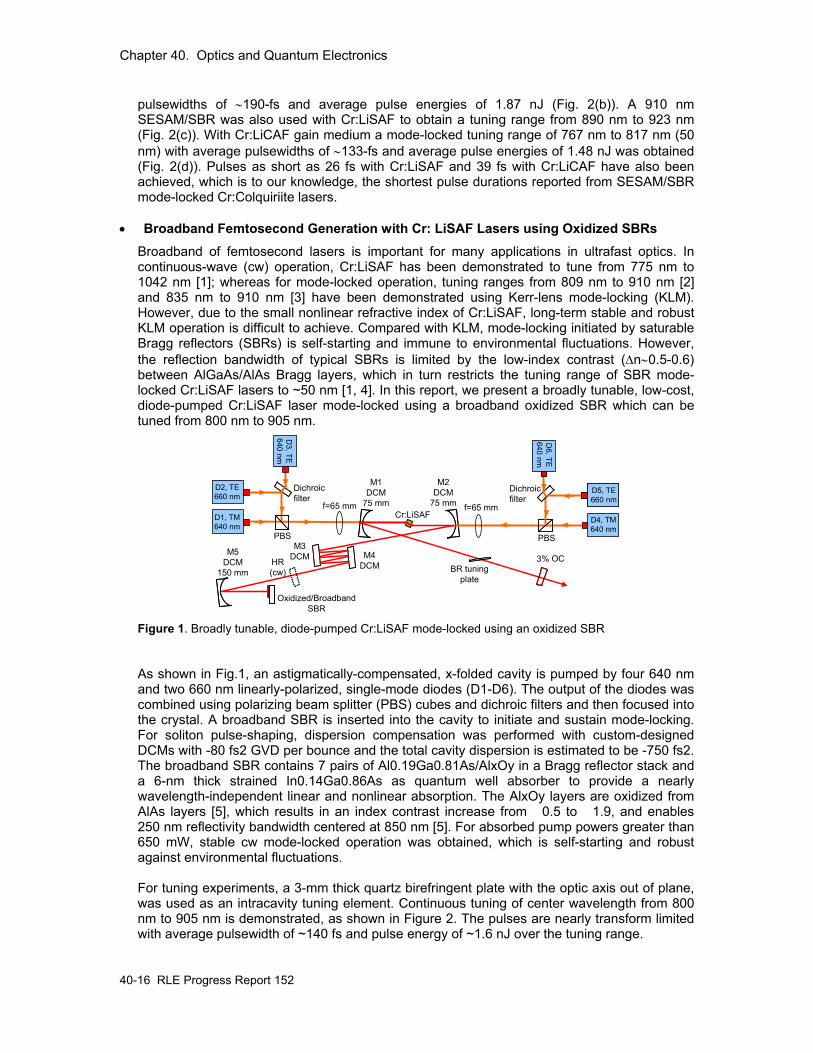
Figure 1. Broadly tunable, diode-pumped Cr:LiSAF mode-locked using an oxidized SBR As shown in Fig.1, an astigmatically-compensated, x-folded cavity is pumped by four 640 nm and two 660 nm linearly-polarized, single-mode diodes (D1-D6). The output of the diodes was combined using polarizing beam splitter (PBS) cubes and dichroic filters and then focused into the crystal. A broadband SBR is inserted into the cavity to initiate and sustain mode-locking. For soliton pulse-shaping, dispersion compensation was performed with custom-designed DCMs with -80 fs2 GVD per bounce and the total cavity dispersion is estimated to be -750 fs2. The broadband SBR contains 7 pairs of Al0.19Ga0.81As/AlxOy in a Bragg reflector stack and a 6-nm thick strained In0.14Ga0.86As as quantum well absorber to provide a nearly wavelength-independent linear and nonlinear absorption. The AlxOy layers are oxidized from AlAs layers [5], which results in an index contrast increase from 0.5 to 1.9, and enables 250 nm reflectivity bandwidth centered at 850 nm [5]. For absorbed pump powers greater than 650 mW, stable cw mode-locked operation was obtained, which is self-starting and robust against environmental fluctuations. For tuning experiments, a 3-mm thick quartz birefringent plate with the optic axis out of plane, was used as an intracavity tuning element. Continuous tuning of center wavelength from 800 nm to 905 nm is demonstrated, as shown in Figure 2. The pulses are nearly transform limited with average pulsewidth of ~140 fs and pulse energy of ~1.6 nJ over the tuning range.
Chapter 40. Optics and Quantum Electronics
40-17
0
0.5
1
1.5
2
2.5
780 800 820 840 860 880 900 920
Wavelength (nm)
Pul
se E
nerg
y (n
J)
0
60
120
180
240
300
Pul
se W
idth
(fs)
Pulse energy
Pulse width
99
99.25
99.5
99.75
100
750 775 800 825 850 875 900 925 950 975Wavelength (nm)
SE
SA
M/S
BR
refle
ctio
n (%
)
-900
-800
-700
-600
-500
Tota
l cav
ity G
VD
(fs^
2)
GVD
Small signal
ref.Sat.ref.
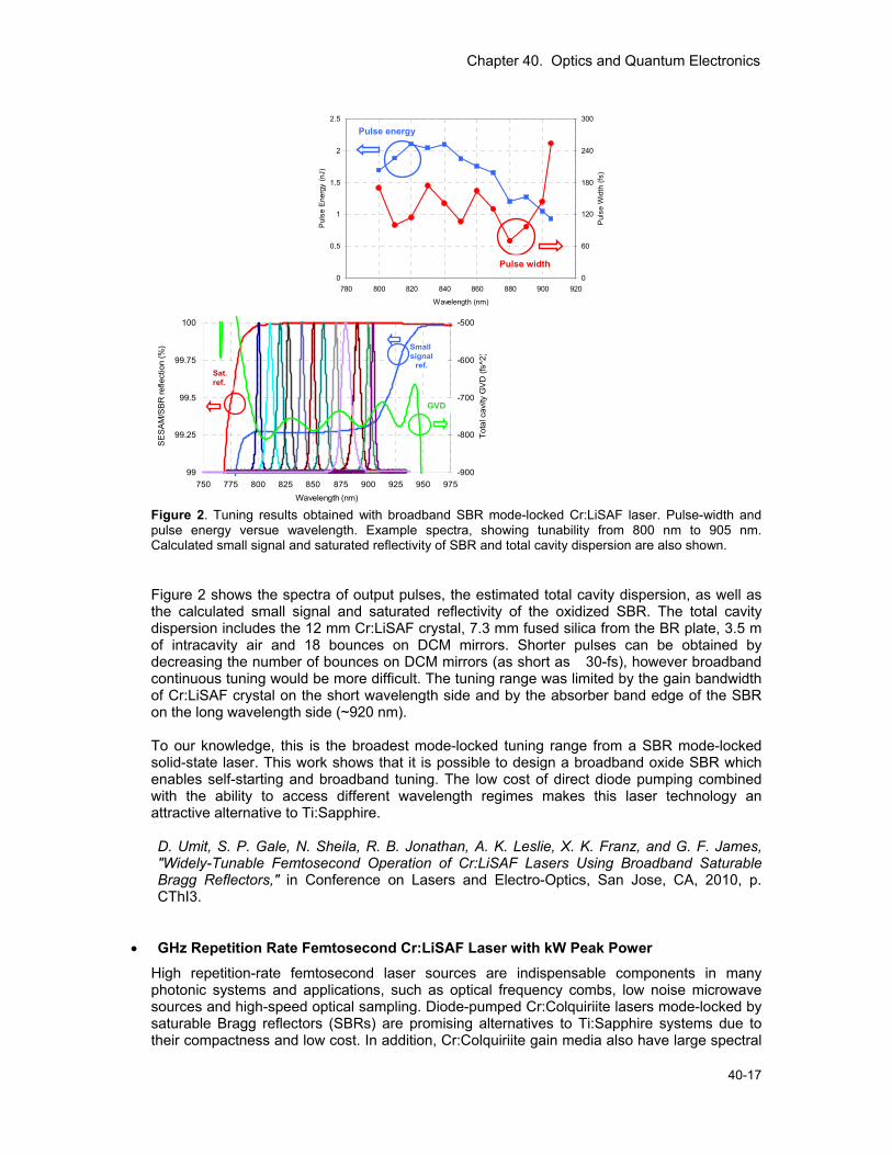
Figure 2. Tuning results obtained with broadband SBR mode-locked Cr:LiSAF laser. Pulse-width and pulse energy versue wavelength. Example spectra, showing tunability from 800 nm to 905 nm. Calculated small signal and saturated reflectivity of SBR and total cavity dispersion are also shown. Figure 2 shows the spectra of output pulses, the estimated total cavity dispersion, as well as the calculated small signal and saturated reflectivity of the oxidized SBR. The total cavity dispersion includes the 12 mm Cr:LiSAF crystal, 7.3 mm fused silica from the BR plate, 3.5 m of intracavity air and 18 bounces on DCM mirrors. Shorter pulses can be obtained by decreasing the number of bounces on DCM mirrors (as short as 30-fs), however broadband continuous tuning would be more difficult. The tuning range was limited by the gain bandwidth of Cr:LiSAF crystal on the short wavelength side and by the absorber band edge of the SBR on the long wavelength side (~920 nm). To our knowledge, this is the broadest mode-locked tuning range from a SBR mode-locked solid-state laser. This work shows that it is possible to design a broadband oxide SBR which enables self-starting and broadband tuning. The low cost of direct diode pumping combined with the ability to access different wavelength regimes makes this laser technology an attractive alternative to Ti:Sapphire. D. Umit, S. P. Gale, N. Sheila, R. B. Jonathan, A. K. Leslie, X. K. Franz, and G. F. James, "Widely-Tunable Femtosecond Operation of Cr:LiSAF Lasers Using Broadband Saturable Bragg Reflectors," in Conference on Lasers and Electro-Optics, San Jose, CA, 2010, p. CThI3.
• GHz Repetition Rate Femtosecond Cr:LiSAF Laser with kW Peak Power High repetition-rate femtosecond laser sources are indispensable components in many photonic systems and applications, such as optical frequency combs, low noise microwave sources and high-speed optical sampling. Diode-pumped Cr:Colquiriite lasers mode-locked by saturable Bragg reflectors (SBRs) are promising alternatives to Ti:Sapphire systems due to their compactness and low cost. In addition, Cr:Colquiriite gain media also have large spectral
Chapter 40. Optics and Quantum Electronics
40-18 RLE Progress Report 152
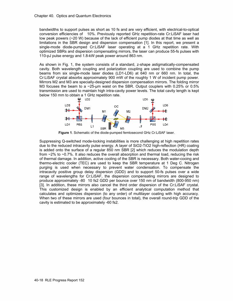
bandwidths to support pulses as short as 10 fs and are very efficient, with electrical-to-optical conversion efficiencies of 10%. Previously reported GHz repetition-rate Cr:LiSAF laser had low peak powers (~20 W) because of the lack of efficient pump diodes at that time as well as limitations in the SBR design and dispersion compensation [1]. In this report, we present a single-mode diode-pumped Cr:LiSAF laser operating at a 1 GHz repetition rate. With optimized SBRs and dispersion compensating mirrors, the laser can produce 55-fs pulses with 110-pJ pulse energy and 1.8-kW peak power around 863 nm. As shown in Fig. 1, the system consists of a standard, z-shape astigmatically-compensated cavity. Both wavelength coupling and polarization coupling are used to combine the pump beams from six single-mode laser diodes (LD1-LD6) at 640 nm or 660 nm. In total, the Cr:LiSAF crystal absorbs approximately 900 mW of the roughly 1 W of incident pump power. Mirrors M2 and M3 are specially-designed dispersion compensation mirrors. The folding mirror M3 focuses the beam to a ~25-μm waist on the SBR. Output couplers with 0.25% or 0.5% transmission are used to maintain high intra-cavity power levels. The total cavity length is kept below 150 mm to obtain a 1 GHz repetition rate.
Figure 1. Schematic of the diode-pumped femtosecond GHz Cr:LiSAF laser.
Suppressing Q-switched mode-locking instabilities is more challenging at high repetition rates due to the reduced intracavity pulse energy. A layer of SiO2-TiO2 high-reflection (HR) coating is added onto the surface of a regular 850 nm SBR [2] which reduces the modulation depth from ~2% to ~0.7%. It also reduces the overall absorption and thermal load, reducing the risk of thermal damage. In addition, active cooling of the SBR is necessary. Both water-cooing and thermo-electric cooler (TEC) are used to keep the SBR temperature at 1 Deg C. Nitrogen purging is used when necessary to prevent water condensation. To compensate the intracavity positive group delay dispersion (GDD) and to support 50-fs pulses over a wide range of wavelengths for Cr:LiSAF, the dispersion compensating mirrors are designed to produce approximately -8010 fs2 GDD per bounce over 150 nm of bandwidth (800-950 nm) [3]. In addition, these mirrors also cancel the third order dispersion of the Cr:LiSAF crystal. This customized design is enabled by an efficient analytical computation method that calculates and optimizes dispersion (to any order) of multilayer coating with high accuracy. When two of these mirrors are used (four bounces in total), the overall round-trip GDD of the cavity is estimated to be approximately -60 fs2.
Chapter 40. Optics and Quantum Electronics
40-19
0 200 400 600 800 10000
20
40
60
80
100
120 cw Q-switched mode-locking cw mode-locking
Out
put p
ower
(mW
)
Absorbed pump power (mW)0.90 0.95 1.00 1.05 1.10
-100
-80
-60
-40
-20
01.0023225 GHz
Inte
nsity
(dB
m)
Frequency (GHz)
-200 -100 0 100 2000.00
0.25
0.50
0.75
1.00τ ~ 55 fs
SHG
inte
nsity
(au)
Delay time (fs)
(a) (b)
(d)(c)
820 840 860 880 9000.00
0.25
0.50
0.75
1.00FWHM ~ 17.3 nm
Pow
er s
pect
ral d
ensi
ty (a
u)
Wavelength (nm)
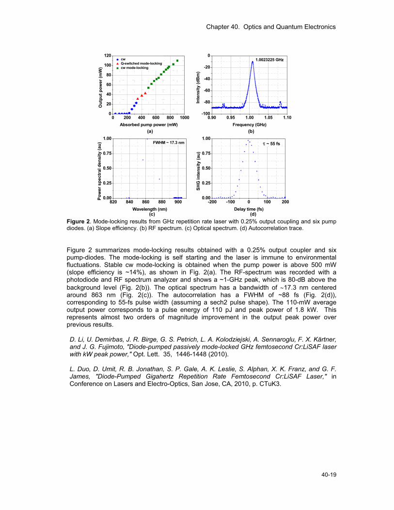
Figure 2. Mode-locking results from GHz repetition rate laser with 0.25% output coupling and six pump diodes. (a) Slope efficiency. (b) RF spectrum. (c) Optical spectrum. (d) Autocorrelation trace. Figure 2 summarizes mode-locking results obtained with a 0.25% output coupler and six pump-diodes. The mode-locking is self starting and the laser is immune to environmental fluctuations. Stable cw mode-locking is obtained when the pump power is above 500 mW (slope efficiency is ~14%), as shown in Fig. 2(a). The RF-spectrum was recorded with a photodiode and RF spectrum analyzer and shows a ~1-GHz peak, which is 80-dB above the background level (Fig. 2(b)). The optical spectrum has a bandwidth of ∼17.3 nm centered around 863 nm (Fig. 2(c)). The autocorrelation has a FWHM of ~88 fs (Fig. 2(d)), corresponding to 55-fs pulse width (assuming a sech2 pulse shape). The 110-mW average output power corresponds to a pulse energy of 110 pJ and peak power of 1.8 kW. This represents almost two orders of magnitude improvement in the output peak power over previous results. D. Li, U. Demirbas, J. R. Birge, G. S. Petrich, L. A. Kolodziejski, A. Sennaroglu, F. X. Kärtner, and J. G. Fujimoto, "Diode-pumped passively mode-locked GHz femtosecond Cr:LiSAF laser with kW peak power," Opt. Lett. 35, 1446-1448 (2010). L. Duo, D. Umit, R. B. Jonathan, S. P. Gale, A. K. Leslie, S. Alphan, X. K. Franz, and G. F. James, "Diode-Pumped Gigahertz Repetition Rate Femtosecond Cr:LiSAF Laser," in Conference on Lasers and Electro-Optics, San Jose, CA, 2010, p. CTuK3.
Chapter 40. Optics and Quantum Electronics
40-20 RLE Progress Report 152
2. Femtosecond Laser Frequency Combs Sponsors Defense Advanced Research Projects Agency (DARPA), HR0011-05-C-0155 Air Force Office of Scientific Research (AFOSR), FA9550-10-1-0063 National Science Foundation (NSF), AST-0905214 and AST-0905592 National Aeronautic and Space Administration (NASA), NNX09AC92G and NNX10AE68G Project Staff Andrew J. Benedick, Li-Jin Chen, Dr. Jonathan R. Birge, Dr. Guoqing (Noah) Chang, Prof. Franz X. Kärtner Collaborators Dr. Ronald L. Walsworth, Dr. David Phillips, and Prof. O. Nohadani Femtosecond laser frequency combs originate from a train of evenly spaced, ultrashort pulses emitted by a mode-locked femtosecond laser. In the frequency domain, such a pulse train translates to a bright spectral comb consisting of millions of discrete optical lines at well-defined frequencies. Controlling the absolute frequency of each component of the output spectrum from the mode locked laser is the defining aspect of a frequency comb. The output spectrum from the comb is described by the spacing between the individual frequency components, frep, as well as the offset of those components from zero frequency, fceo. Knowing and controlling these two frequencies, allows all other frequencies generated from the laser to be simply defined as, f = fceo + m×frep, where m is an integer. This control can be achieved in many different ways, each of which having different strengths and weaknesses that should be tailored to the expected manner in which the comb will be used for best results. Femtosecond laser frequency combs have enabled a wide range of scientific and technological advances, such as high-speed optical sampling, timing and frequency distribution systems, optical arbitrary waveform generation, laser radar (i.e., using laser light to determine the position, velocity, and characteristics of distant objects) with sensitivity and range improved by orders of magnitude, measurements of phase-sensitive high-field processes. One of the more recently proposed applications for frequency comb technology is the calibration of astronomical spectrographs. Highly precise and highly accurate calibration of astronomical spectrographs is necessary to enable astronomers to use the radial velocity method to search for planets outside our solar system. In this method, astronomers monitor the light emitted from stars to observe a slight periodic shift in the emitted spectrum caused by the motion of the star induced by an orbiting planet. In this application, both the accuracy and precision of the frequency comb (termed ‘astro-comb’) will be utilized to enable searches for earth like planets and solar systems. Our research has focused on developing astro-combs based on Ti:sapphire lasers. Using second harmonic generation, we have demonstrated a blue astro-comb that enabled us to calibrate the TRES spectrograph at the Fred Lawrence Whipple Observatory. To achieve a broadband coverage, we have proposed using highly nonlinear fibers to spectrally broaden a narrowband astro-comb. An astro-comb consists of a source comb with moderate comb spacing (~ 1GHz) and a subsequent Fabry-Perot filtering cavity to increase the comb spacing up to tens of GHz. Traditional design of cavity mirrors limits the filtering bandwidth to <40 nm in the visible wavelength range. To overcome this severe limitation, we have proposed and demonstrated a novel cavity design based on a complementary dispersion mirror set. To further optimize cavity mirrors’ performance, we have developed a robust optimization algorithm that is capable of significantly improving the yield of thin film coatings when manufactured in the presence of random thickness errors.
Chapter 40. Optics and Quantum Electronics
40-21
Recent accomplishments:
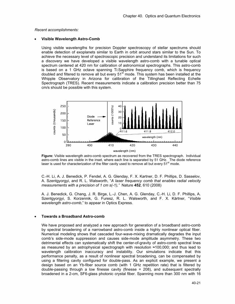
• Visible Wavelength Astro-Comb Using visible wavelengths for precision Doppler spectroscopy of stellar spectrums should enable detection of exoplanets similar to Earth in orbit around stars similar to the Sun. To achieve the necessary level of spectroscopic precision and understand its limitations for such a discovery we have developed a visible wavelength astro-comb with a tunable optical spectrum centered at 420 nm for calibration of astronomical spectrographs. This astro-comb is based on a 1 GHz octave spanning Ti:Sapphire frequency comb, which is frequency doubled and filtered to remove all but every 51st mode. This system has been installed at the Whipple Observatory in Arizona for calibration of the Tillinghast Reflecting Echelle Spectrograph (TRES). Recent measurements indicate a calibration precision better than 75 cm/s should be possible with this system.
Figure: Visible wavelength astro-comb spectrum as recovered from the TRES spectrograph. Individual astro-comb lines are visible in the inset, where each line is separated by 51 GHz. The diode reference laser is used for characterization of the filter cavity used to remove all but every 51st mode.
C.-H. Li, A. J. Benedick, P. Fendel, A. G. Glenday, F. X. Kartner, D. F. Phillips, D. Sasselov, A. Szentgyorgyi, and R. L. Walsworth, “A laser frequency comb that enables radial velocity measurements with a precision of 1 cm s(-1),” Nature 452, 610 (2008) A. J. Benedick, G. Chang, J. R. Birge, L.-J. Chen, A. G. Glenday, C.-H. Li, D. F. Phillips, A. Szentgyorgyi, S. Korzennik, G. Furesz, R. L. Walsworth, and F. X. Kärtner, “Visible wavelength astro-comb,” to appear in Optics Express.
• Towards a Broadband Astro-comb
We have proposed and analyzed a new approach for generation of a broadband astro-comb by spectral broadening of a narrowband astro-comb inside a highly nonlinear optical fiber. Numerical modeling shows that cascaded four-wave-mixing dramatically degrades the input comb’s side-mode suppression and causes side-mode amplitude asymmetry. These two detrimental effects can systematically shift the center-of-gravity of astro-comb spectral lines as measured by an astrophysical spectrograph with resolution ≈100,000; and thus lead to wavelength calibration inaccuracy and instability. Our simulations indicate that this performance penalty, as a result of nonlinear spectral broadening, can be compensated by using a filtering cavity configured for double-pass. As an explicit example, we present a design based on an Yb-fiber source comb (with 1 GHz repetition rate) that is filtered by double-passing through a low finesse cavity (finesse = 208), and subsequent spectrally broadened in a 2-cm, SF6-glass photonic crystal fiber. Spanning more than 300 nm with 16
Chapter 40. Optics and Quantum Electronics
40-22 RLE Progress Report 152
GHz line spacing, the resulting astro-comb is predicted to provide 1 cm/s (~10 kHz) radial velocity calibration accuracy for an astrophysical spectrograph. Such extreme performance will be necessary for the search for and characterization of Earth-like extra-solar planets, and in direct measurements of the change of the rate of cosmological expansion. G. Q. Chang, C. –H. Li, D. F. Phillips, R. L. Walsworth, and F. X. Kaertner, “Toward a broadband astro-combs: Effects of nonlinear spectral broadening in optical fibers,” Opt. Express 18, 12736 (2010)
• High-Finesse Dispersion-Free Cavities for Broadband Filtration of Laser Comb Lines
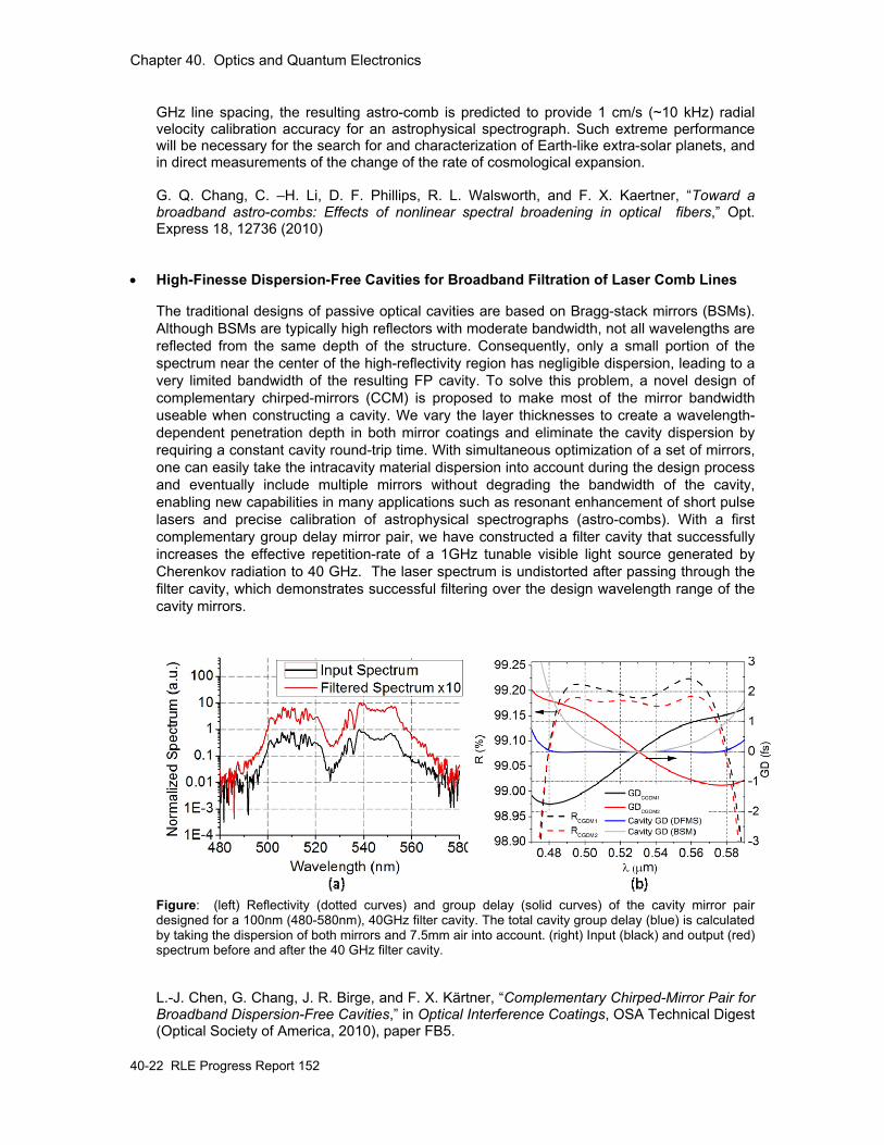
The traditional designs of passive optical cavities are based on Bragg-stack mirrors (BSMs). Although BSMs are typically high reflectors with moderate bandwidth, not all wavelengths are reflected from the same depth of the structure. Consequently, only a small portion of the spectrum near the center of the high-reflectivity region has negligible dispersion, leading to a very limited bandwidth of the resulting FP cavity. To solve this problem, a novel design of complementary chirped-mirrors (CCM) is proposed to make most of the mirror bandwidth useable when constructing a cavity. We vary the layer thicknesses to create a wavelength-dependent penetration depth in both mirror coatings and eliminate the cavity dispersion by requiring a constant cavity round-trip time. With simultaneous optimization of a set of mirrors, one can easily take the intracavity material dispersion into account during the design process and eventually include multiple mirrors without degrading the bandwidth of the cavity, enabling new capabilities in many applications such as resonant enhancement of short pulse lasers and precise calibration of astrophysical spectrographs (astro-combs). With a first complementary group delay mirror pair, we have constructed a filter cavity that successfully increases the effective repetition-rate of a 1GHz tunable visible light source generated by Cherenkov radiation to 40 GHz. The laser spectrum is undistorted after passing through the filter cavity, which demonstrates successful filtering over the design wavelength range of the cavity mirrors.
Figure: (left) Reflectivity (dotted curves) and group delay (solid curves) of the cavity mirror pair designed for a 100nm (480-580nm), 40GHz filter cavity. The total cavity group delay (blue) is calculated by taking the dispersion of both mirrors and 7.5mm air into account. (right) Input (black) and output (red) spectrum before and after the 40 GHz filter cavity.
L.-J. Chen, G. Chang, J. R. Birge, and F. X. Kärtner, “Complementary Chirped-Mirror Pair for Broadband Dispersion-Free Cavities,” in Optical Interference Coatings, OSA Technical Digest (Optical Society of America, 2010), paper FB5.
Chapter 40. Optics and Quantum Electronics
40-23
G. Chang, L.-J. Chen, and F. X. Kärtner, “Highly efficient Cherenkov radiation in photonic crystal fibers for broadband visible wavelength generation,” Opt. Lett. 35, 2361-2363, 2010.
L.–J. Chen, G. Q. Chang, C. –H. Li, A. G. Glenday, A. J. Benedick, D. F. Phillips, R. L. Walsworth, and F. X. Kaertner, “High-finesse dispersion-free cavities for broadband filtration of laser comb lines,” paper TUF1, presented at 17th international conference on Ultrafast Phenomena, Snowmass village, CO, 2010
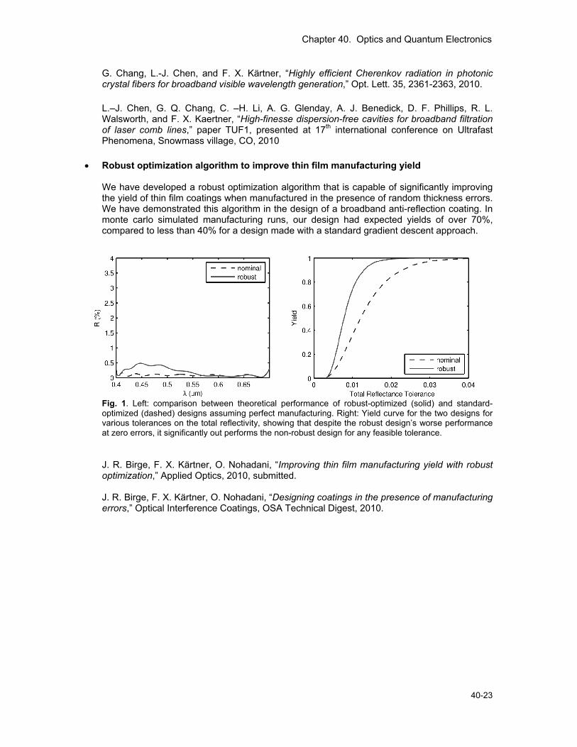
• Robust optimization algorithm to improve thin film manufacturing yield We have developed a robust optimization algorithm that is capable of significantly improving the yield of thin film coatings when manufactured in the presence of random thickness errors. We have demonstrated this algorithm in the design of a broadband anti-reflection coating. In monte carlo simulated manufacturing runs, our design had expected yields of over 70%, compared to less than 40% for a design made with a standard gradient descent approach.
Fig. 1. Left: comparison between theoretical performance of robust-optimized (solid) and standard-optimized (dashed) designs assuming perfect manufacturing. Right: Yield curve for the two designs for various tolerances on the total reflectivity, showing that despite the robust design’s worse performance at zero errors, it significantly out performs the non-robust design for any feasible tolerance. J. R. Birge, F. X. Kärtner, O. Nohadani, “Improving thin film manufacturing yield with robust optimization,” Applied Optics, 2010, submitted.
J. R. Birge, F. X. Kärtner, O. Nohadani, “Designing coatings in the presence of manufacturing errors,” Optical Interference Coatings, OSA Technical Digest, 2010.
Chapter 40. Optics and Quantum Electronics
40-24 RLE Progress Report 152
3. Attosecond Science and High Harmonic Generation Sponsors Air Force Office of Scientific Research (“DARPA HRS”) FA9550-08-1-0409 Air Force Office of Scientific Research FA9550-09-1-0212 Air Force Office of Scientific Research FA9550-10-1-0063 Rocca Foundation Project Staff Dr. Jeffrey Moses, Dr. Kyung-Han Hong, Dr. Edilson L. Falcão-Filho, Shu-Wei Huang, Giovanni Cirmi, Chien-Jen Lai, Vasileios Gkortsas, Siddharth Bhardwaj, William Putnam, Alexander Soane, P. Donald Keathley, Aleem Siddiqui, Andrew Benedick, Li-Jin Chen, Jonathan R. Birge, and Prof. Franz X. Kärtner Collaborators Dr. T. Y. Fan, Dr. Juliet Gopinath, Dr. D. Rand, Dr. D. Ripin, Dr. Cristian Manzoni, Prof. Giulio Cerullo, Dr. Enbang Li, and Prof. Benjamin Eggleton The field of ultrafast optics is now extended to the attosecond regime, while ultrafast tabletop coherent radiation sources generate wavelengths in the extreme ultraviolet (EUV) (120 – 10 nm) and soft x-ray (10 - 0.1 nm) range. These technologies are enabling new fields of study, including time-resolved investigation of ionization processes, imaging of molecular orbitals and electron wavepacket dynamics, and soft x-ray lensless imaging and water-window imaging in a tabletop set-up. The sources are based on high intensity ultrafast lasers and amplifiers that are focused into noble gases to produce high-order harmonics of the laser frequency by a non-perturbative nonlinear optical process. Termed High Harmonic Generation (HHG), it involves laser-induced electron ionization, acceleration and recombination, and phase-matched radiation, processes that depend critically on laser parameters such as frequency and intensity, and material properties such as ionization threshold, dipole transition probabilities, and linear refraction. The success of attosecond science and other applications of the available laboratory HHG-based ultrafast EUV and soft x-ray sources depends on the development of robust, high power, and optimal laser sources, as well as a sophisticated understanding of the factors affecting HHG efficiency. Our research program combines these two aspects. (i) We are developing ultrabroadband optical parametric chirped pulse amplifiers (OPCPAs) at near- and mid-infrared wavelengths that are groundbreaking both in pulse duration and average power. Towards these aims, we recently synthesized high-energy sub-cycle optical pulses by locking the output of 800-nm and 2-micron wavelength OPCPAs both in phase and in timing. The combined spectrum spans 1.5 octaves, and has the capability of producing 2-fs, 0.55-cycle pulses, a pulse width ideal for efficiently generating isolated attosecond pulses through HHG. We are pushing the power envelope by integrating our 100-W 1-micron laser system, based on cryogenically cooled Yb:YAG, with our OPCPAs as the pump laser. (ii) We are investigating the scaling of HHG efficiency through experiments, analytics, and time-resolved Schrodinger equation simulations. Our efforts are focused on drive-laser wavelength scaling and ionization dynamics. Finally, supporting our program in attosecond science, we are constructing characterization methods for attosecond pulse metrology.
Chapter 40. Optics and Quantum Electronics
40-25
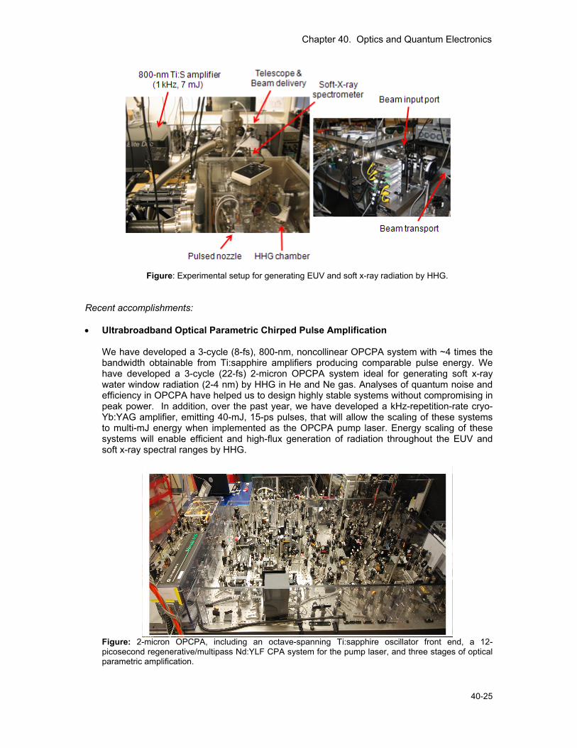
Figure: Experimental setup for generating EUV and soft x-ray radiation by HHG.
Recent accomplishments: • Ultrabroadband Optical Parametric Chirped Pulse Amplification
We have developed a 3-cycle (8-fs), 800-nm, noncollinear OPCPA system with ~4 times the bandwidth obtainable from Ti:sapphire amplifiers producing comparable pulse energy. We have developed a 3-cycle (22-fs) 2-micron OPCPA system ideal for generating soft x-ray water window radiation (2-4 nm) by HHG in He and Ne gas. Analyses of quantum noise and efficiency in OPCPA have helped us to design highly stable systems without compromising in peak power. In addition, over the past year, we have developed a kHz-repetition-rate cryo-Yb:YAG amplifier, emitting 40-mJ, 15-ps pulses, that will allow the scaling of these systems to multi-mJ energy when implemented as the OPCPA pump laser. Energy scaling of these systems will enable efficient and high-flux generation of radiation throughout the EUV and soft x-ray spectral ranges by HHG.
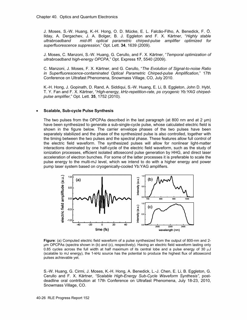
Figure: 2-micron OPCPA, including an octave-spanning Ti:sapphire oscillator front end, a 12-picosecond regenerative/multipass Nd:YLF CPA system for the pump laser, and three stages of optical parametric amplification.
Chapter 40. Optics and Quantum Electronics
40-26 RLE Progress Report 152
J. Moses, S.-W. Huang, K.-H. Hong, O. D. Mücke, E. L. Falcão-Filho, A. Benedick, F. Ö. Ilday, A. Dergachev, J. A. Bolger, B. J. Eggleton and F. X. Kärtner, “Highly stable ultrabroadband mid-IR optical parametric chirped-pulse amplifier optimized for superfluorescence suppression,” Opt. Lett. 34, 1639 (2009).
J. Moses, C. Manzoni, S.-W. Huang, G. Cerullo, and F. X. Kärtner, “Temporal optimization of ultrabroadband high-energy OPCPA,” Opt. Express 17, 5540 (2009). C. Manzoni, J. Moses, F. X. Kärtner, and G. Cerullo, “The Evolution of Signal-to-noise Ratio in Superfluorescence-contaminated Optical Parametric Chirped-pulse Amplification,” 17th Conference on Ultrafast Phenomena, Snowmass Village, CO, July 2010.
K.-H. Hong, J. Gopinath, D. Rand, A. Siddiqui, S.-W. Huang, E. Li, B. Eggleton, John D. Hybl, T. Y. Fan and F. X. Kärtner, “High-energy, kHz-repetition-rate, ps cryogenic Yb:YAG chirped-pulse amplifier,” Opt. Lett. 35, 1752 (2010).
• Scalable, Sub-cycle Pulse Synthesis
The two pulses from the OPCPAs described in the last paragraph (at 800 nm and at 2 µm) have been synthesized to generate a sub-single-cycle pulse, whose calculated electric field is shown in the figure below. The carrier envelope phases of the two pulses have been separately stabilized and the phase of the synthesized pulse is also controlled, together with the timing between the two pulses and the spectral phase. These features allow full control of the electric field waveform. The synthesized pulses will allow for nonlinear light-matter interactions dominated by one half-cycle of the electric field waveform, such as the study of ionization processes, efficient isolated attosecond pulse generation by HHG, and direct laser acceleration of electron bunches. For some of the latter processes it is preferable to scale the pulse energy to the multi-mJ level, which we intend to do with a higher energy and power pump laser system based on cryogenically-cooled Yb:YAG amplifiers.
-40 -20 0 20 40
-1.0
-0.5
0.0
0.5
1.0
elec
tric
field
am
plift
ude
(a.u
.)
time (fs)
(a) (b)
700 800 900 10000.0
0.5
1.0
inte
nsity
(a.u
.)
2000 2200 24000.0
0.5
1.0
inte
nsity
(a.u
.)
wavelength (nm)
(c)
-40 -20 0 20 40
-1.0
-0.5
0.0
0.5
1.0
elec
tric
field
am
plift
ude
(a.u
.)
time (fs)
(a) (b)
700 800 900 10000.0
0.5
1.0
inte
nsity
(a.u
.)
2000 2200 24000.0
0.5
1.0
inte
nsity
(a.u
.)
wavelength (nm)
(c)
Figure: (a) Computed electric field waveform of a pulse synthesized from the output of 800-nm and 2-µm OPCPAs (spectra shown in (b) and (c), respectively). Having an electric field waveform lasting only 0.85 cycles across the full width at half maximum of its central lobe and a pulse energy of 30 μJ (scalable to mJ energy), the 1-kHz source has the potential to produce the highest flux of attosecond pulses achievable yet.
S.-W. Huang, G. Cirmi, J. Moses, K.-H. Hong, A. Benedick, L.-J. Chen, E. Li, B. Eggleton, G. Cerullo and F. X. Kärtner, “Scalable High-Energy Sub-Cycle Waveform Synthesis”, post-deadline oral contribution at 17th Conference on Ultrafast Phenomena, July 18-23, 2010, Snowmass Village, CO.
Chapter 40. Optics and Quantum Electronics
40-27
• High-Harmonic Efficiencies studied with 400 and 800 nm Pulses
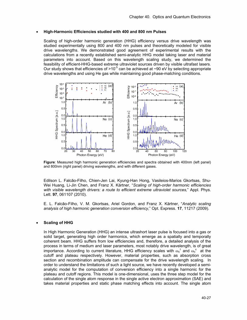
Scaling of high-order harmonic generation (HHG) efficiency versus drive wavelength was studied experimentally using 800 and 400 nm pulses and theoretically modeled for visible drive wavelengths. We demonstrated good agreement of experimental results with the calculations from a recently established semi-analytic HHG model taking laser and material parameters into account. Based on this wavelength scaling study, we determined the feasibility of efficient-HHG-based extreme ultraviolet sources driven by visible ultrafast lasers. Our study shows that efficiencies of >10-5 can be achieved at ~90 eV by selecting appropriate drive wavelengths and using He gas while maintaining good phase-matching conditions.
Figure: Measured high harmonic generation efficiencies and spectra obtained with 400nm (left panel) and 800nm (right panel) driving wavelengths, and with different gases.
Edilson L. Falcão-Filho, Chien-Jen Lai, Kyung-Han Hong, Vasileios-Marios Gkortsas, Shu-Wei Huang, Li-Jin Chen, and Franz X. Kärtner, “Scaling of high-order harmonic efficiencies with visible wavelength drivers: a route to efficient extreme ultraviolet sources,” Appl. Phys. Lett. 97, 061107 (2010). E. L. Falcão-Filho, V. M. Gkortsas, Ariel Gordon, and Franz X. Kärtner, “Analytic scaling analysis of high harmonic generation conversion efficiency,” Opt. Express. 17, 11217 (2009).
• Scaling of HHG
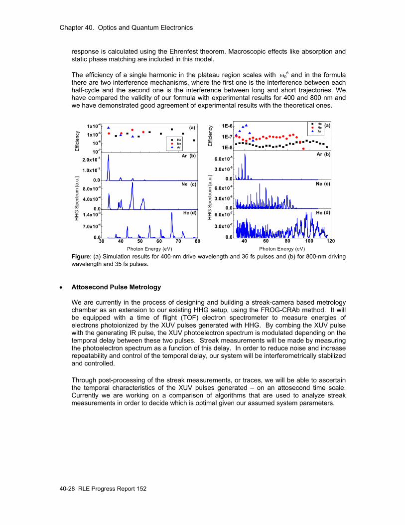
In High Harmonic Generation (HHG) an intense ultrashort laser pulse is focused into a gas or solid target, generating high order harmonics, which emerge as a spatially and temporally coherent beam. HHG suffers from low efficiencies and, therefore, a detailed analysis of the process in terms of medium and laser parameters, most notably drive wavelength, is of great importance. According to current literature, HHG efficiency scales with ω0
5 and ω06 at the
cutoff and plateau respectively. However, material properties, such as absorption cross section and recombination amplitude can compensate for the drive wavelength scaling. In order to understand the limitations of such a light source, we have recently developed a semi-analytic model for the computation of conversion efficiency into a single harmonic for the plateau and cutoff regions. This model is one-dimensional, uses the three step model for the calculation of the single atom response in the single active electron approximation (SAE) and takes material properties and static phase matching effects into account. The single atom
Chapter 40. Optics and Quantum Electronics
40-28 RLE Progress Report 152
response is calculated using the Ehrenfest theorem. Macroscopic effects like absorption and static phase matching are included in this model. The efficiency of a single harmonic in the plateau region scales with ω0
6 and in the formula there are two interference mechanisms, where the first one is the interference between each half-cycle and the second one is the interference between long and short trajectories. We have compared the validity of our formula with experimental results for 400 and 800 nm and we have demonstrated good agreement of experimental results with the theoretical ones.
30 40 50 60 70 800.0
7.0x10⁻⁴
1.4x10⁻³
Photon Energy (eV)
0.0
4.0x10⁻⁴
8.0x10⁻⁴
HH
G S
pect
rum
[a.u
.] 0.0
1.0x10⁻³
2.0x10⁻³
(c)
(d)
(b)
(a)
He
Ne
Ar
10-7
10-6
1x10⁻⁵
1x10⁻⁴
He Ne ArEf
ficie
ncy
40 60 80 100 1200.0
3.0x10⁻⁷
6.0x10⁻⁷ (d)
Photon Energy (eV)
0.0
3.0x10⁻⁶
6.0x10⁻⁶ (c)
HH
G S
pect
rum
[a.u
.] 0.0
3.0x10⁻⁵
6.0x10⁻⁵(b)
(a)
He
Ne
Ar
1E-8
1E-7
1E-6 He Ne Ar
Effi
cien
cy
Figure: (a) Simulation results for 400-nm drive wavelength and 36 fs pulses and (b) for 800-nm driving wavelength and 35 fs pulses.
• Attosecond Pulse Metrology
We are currently in the process of designing and building a streak-camera based metrology chamber as an extension to our existing HHG setup, using the FROG-CRAb method. It will be equipped with a time of flight (TOF) electron spectrometer to measure energies of electrons photoionized by the XUV pulses generated with HHG. By combing the XUV pulse with the generating IR pulse, the XUV photoelectron spectrum is modulated depending on the temporal delay between these two pulses. Streak measurements will be made by measuring the photoelectron spectrum as a function of this delay. In order to reduce noise and increase repeatability and control of the temporal delay, our system will be interferometrically stabilized and controlled. Through post-processing of the streak measurements, or traces, we will be able to ascertain the temporal characteristics of the XUV pulses generated – on an attosecond time scale. Currently we are working on a comparison of algorithms that are used to analyze streak measurements in order to decide which is optimal given our assumed system parameters.
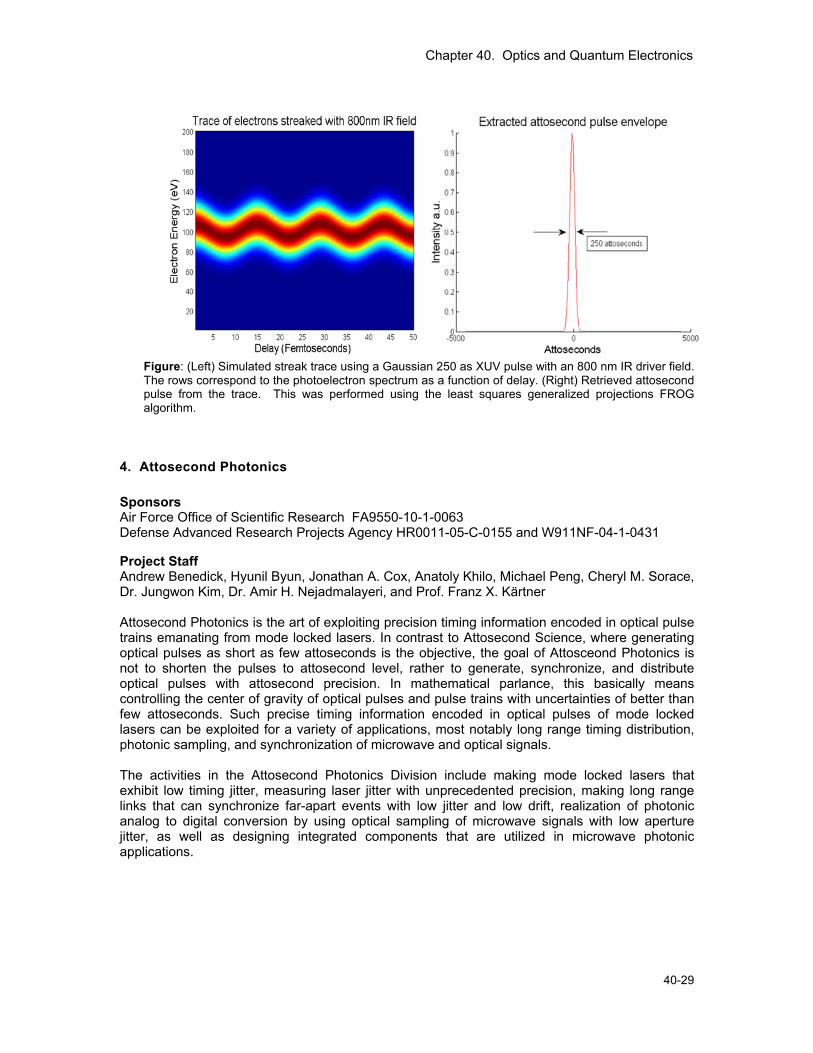
Chapter 40. Optics and Quantum Electronics
40-29
Figure: (Left) Simulated streak trace using a Gaussian 250 as XUV pulse with an 800 nm IR driver field. The rows correspond to the photoelectron spectrum as a function of delay. (Right) Retrieved attosecond pulse from the trace. This was performed using the least squares generalized projections FROG algorithm.
4. Attosecond Photonics
Sponsors Air Force Office of Scientific Research FA9550-10-1-0063 Defense Advanced Research Projects Agency HR0011-05-C-0155 and W911NF-04-1-0431
Project Staff Andrew Benedick, Hyunil Byun, Jonathan A. Cox, Anatoly Khilo, Michael Peng, Cheryl M. Sorace, Dr. Jungwon Kim, Dr. Amir H. Nejadmalayeri, and Prof. Franz X. Kärtner Attosecond Photonics is the art of exploiting precision timing information encoded in optical pulse trains emanating from mode locked lasers. In contrast to Attosecond Science, where generating optical pulses as short as few attoseconds is the objective, the goal of Attosceond Photonics is not to shorten the pulses to attosecond level, rather to generate, synchronize, and distribute optical pulses with attosecond precision. In mathematical parlance, this basically means controlling the center of gravity of optical pulses and pulse trains with uncertainties of better than few attoseconds. Such precise timing information encoded in optical pulses of mode locked lasers can be exploited for a variety of applications, most notably long range timing distribution, photonic sampling, and synchronization of microwave and optical signals. The activities in the Attosecond Photonics Division include making mode locked lasers that exhibit low timing jitter, measuring laser jitter with unprecedented precision, making long range links that can synchronize far-apart events with low jitter and low drift, realization of photonic analog to digital conversion by using optical sampling of microwave signals with low aperture jitter, as well as designing integrated components that are utilized in microwave photonic applications.
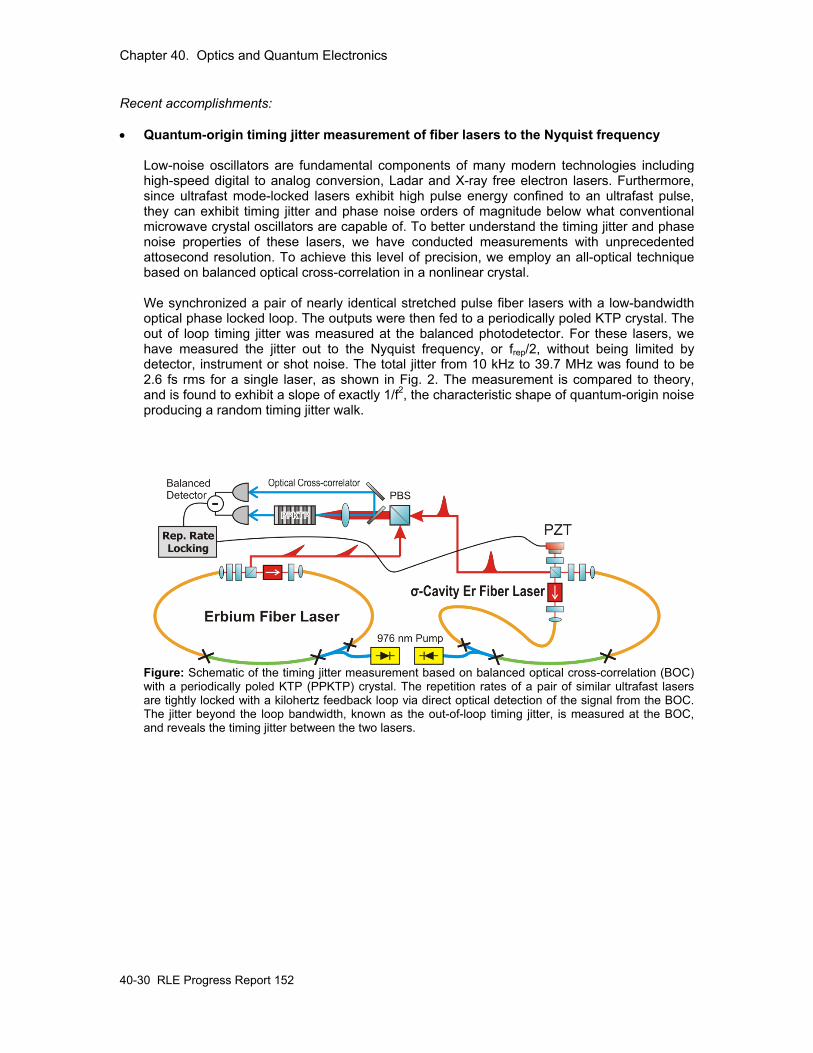
Chapter 40. Optics and Quantum Electronics
40-30 RLE Progress Report 152
Recent accomplishments: • Quantum-origin timing jitter measurement of fiber lasers to the Nyquist frequency
Low-noise oscillators are fundamental components of many modern technologies including high-speed digital to analog conversion, Ladar and X-ray free electron lasers. Furthermore, since ultrafast mode-locked lasers exhibit high pulse energy confined to an ultrafast pulse, they can exhibit timing jitter and phase noise orders of magnitude below what conventional microwave crystal oscillators are capable of. To better understand the timing jitter and phase noise properties of these lasers, we have conducted measurements with unprecedented attosecond resolution. To achieve this level of precision, we employ an all-optical technique based on balanced optical cross-correlation in a nonlinear crystal. We synchronized a pair of nearly identical stretched pulse fiber lasers with a low-bandwidth optical phase locked loop. The outputs were then fed to a periodically poled KTP crystal. The out of loop timing jitter was measured at the balanced photodetector. For these lasers, we have measured the jitter out to the Nyquist frequency, or frep/2, without being limited by detector, instrument or shot noise. The total jitter from 10 kHz to 39.7 MHz was found to be 2.6 fs rms for a single laser, as shown in Fig. 2. The measurement is compared to theory, and is found to exhibit a slope of exactly 1/f2, the characteristic shape of quantum-origin noise producing a random timing jitter walk.
Figure: Schematic of the timing jitter measurement based on balanced optical cross-correlation (BOC) with a periodically poled KTP (PPKTP) crystal. The repetition rates of a pair of similar ultrafast lasers are tightly locked with a kilohertz feedback loop via direct optical detection of the signal from the BOC. The jitter beyond the loop bandwidth, known as the out-of-loop timing jitter, is measured at the BOC, and reveals the timing jitter between the two lasers.
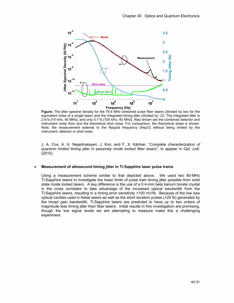
Chapter 40. Optics and Quantum Electronics
40-31
103
104
105
106
107
10-12
10-10
10-8
10-6
10-4
10-2
103
104
105
106
107
0
0.5
1
1.5
2
2.5
3
3.5
Jitte
r Spe
ctra
l Den
sity
(fs2 /H
z)
Frequency (Hz)
Model
Measurement
Shot noise
Noise floor
Tim
ing
Jitte
r (fs
)
103
Figure: The jitter spectral density for the 79.4 MHz stretched pulse fiber lasers (divided by two for the equivalent noise of a single laser) and the integrated timing jitter (divided by √2). The integrated jitter is 2.6 fs [10 kHz, 40 MHz], and only 0.7 fs [100 kHz, 40 MHz]. Also shown are the combined detector and instrument noise floor and the theoretical shot noise. For comparison, the theoretical slope is shown. Note, the measurement extends to the Nyquist frequency (frep/2) without being limited by the instrument, detector or shot noise. J. A. Cox, A. H. Nejadmalayeri, J. Kim, and F. X. Kärtner, “Complete characterization of quantum limited timing jitter in passively mode locked fiber lasers”, to appear in Opt. Lett. (2010).
• Measurement of attosecond timing jitter in Ti:Sapphire laser pulse trains Using a measurement scheme similar to that depicted above. We used two 80-MHz Ti:Sapphire lasers to investigate the lower limits of pulse train timing jitter possible from solid state mode locked lasers. A key difference is the use of a 0.4-mm beta barium borate crystal in the cross correlator to take advantage of the increased optical bandwidth from the Ti:Sapphire lasers, resulting in a timing error sensitivity >100 mV/fs. Because of the low loss optical cavities used in these lasers as well as the short duration pulses (<20 fs) generated by the broad gain bandwidth, Ti:Sapphire lasers are predicted to have up to two orders of magnitude less timing jitter than fiber lasers. Initial results in this investigation are promising, though the low signal levels we are attempting to measure make this a challenging experiment.
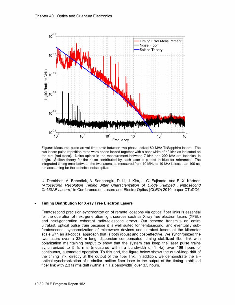
Chapter 40. Optics and Quantum Electronics
40-32 RLE Progress Report 152
102 103 104 105 106 10710-22
10-20
10-18
10-16
10-14
10-12
Frequency
log1
0(R
adia
ns2 /H
z)Timing Error MeasurementNoise FloorSoliton Theory
Figure: Measured pulse arrival time error between two phase locked 80 MHz Ti:Sapphire lasers. The two lasers pulse repetition rates were phase locked together with a bandwidth of ~2 kHz as indicated on the plot (red trace). Noise spikes in the measurement between 7 kHz and 200 kHz are technical in origin. Soliton theory for the noise contributed by each laser is plotted in blue for reference. The integrated timing error between the two lasers, as measured from 10 MHz to 10 kHz is less than 100 as, not accounting for the technical noise spikes. U. Demirbas, A. Benedick, A. Sennaroglu, D. Li, J. Kim, J. G. Fujimoto, and F. X. Kärtner, "Attosecond Resolution Timing Jitter Characterization of Diode Pumped Femtosecond Cr:LiSAF Lasers," in Conference on Lasers and Electro-Optics (CLEO) 2010, paper CTuDD6.
• Timing Distribution for X-ray Free Electron Lasers Femtosecond precision synchronization of remote locations via optical fiber links is essential for the operation of next-generation light sources such as X-ray free electron lasers (XFEL) and next-generation coherent radio-telescope arrays. Our scheme transmits an entire ultrafast, optical pulse train because it is well suited for femtosecond, and eventually sub-femtosecond, synchronization of microwave devices and ultrafast lasers at the kilometer scale with an all-optical approach that is both robust and cost-effective. We synchronized the two lasers over a 320-m long, dispersion compensated, timing stabilized fiber link with polarization maintaining output to show that the system can keep the laser pulse trains synchronized to 5 fs rms (measured within a bandwidth of 1 Hz) over 168 hours of continuous, automated operation. To this end, the figure below shows the out-of-loop drift of the timing link, directly at the output of the fiber link. In addition, we demonstrate the all-optical synchronization of a similar, soliton fiber laser to the output of the timing stabilized fiber link with 2.3 fs rms drift (within a 1 Hz bandwidth) over 3.5 hours.
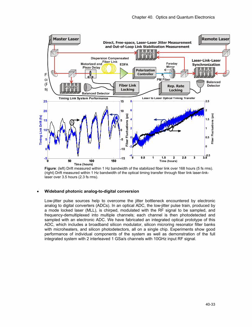
Chapter 40. Optics and Quantum Electronics
40-33
Figure: The fiber link synchronization system and laser noise measurement apparatus. It consists of a 320 m, stabilized fiber link with multiple balanced optical cross-correlators (PPKTP) for fiber link timing stabilization, laser-link-laser optical synchronization and free-space, laser-to-laser timing jitter measurement.
0 0.5 1 1.5 2 2.5 3 3.5-4
-2
0
2
4
6
8
Rem
ote
to L
ocal
Las
er D
rift (
fs)
Time (hours)0 0.5 1 1.5 2 2.5 3 3.5
-0.5
0
0.5
1
1.5
2
2.5
Fibe
r Fl
uctu
atio
ns (p
s)
Laser to Laser Optical Timing Transfer
0 50 100 150-5
0
5
10
15
20
25
Tim
ing
Link
Dri
ft (f
s)
Time (hours)0 50 100 150
-15
-10
-5
0
5
10
15
Fibe
r Fl
uctu
atio
ns (p
s)
Timing Link System Performance
Figure: (left) Drift measured within 1 Hz bandwidth of the stabilized fiber link over 168 hours (5 fs rms). (right) Drift measured within 1 Hz bandwidth of the optical timing transfer through fiber link laser-link-laser over 3.5 hours (2.3 fs rms).
• Wideband photonic analog-to-digital conversion Low-jitter pulse sources help to overcome the jitter bottleneck encountered by electronic analog to digital converters (ADCs). In an optical ADC, the low-jitter pulse train, produced by a mode locked laser (MLL), is chirped, modulated with the RF signal to be sampled, and frequency-demultiplexed into multiple channels; each channel is then photodetected and sampled with an electronic ADC. We have fabricated an integrated optical prototype of this ADC, which includes a broadband silicon modulator, silicon microring resonator filter banks with microheaters, and silicon photodetectors, all on a single chip. Experiments show good performance of individual components of the system as well as demonstration of the full integrated system with 2 interleaved 1 GSa/s channels with 10GHz input RF signal.
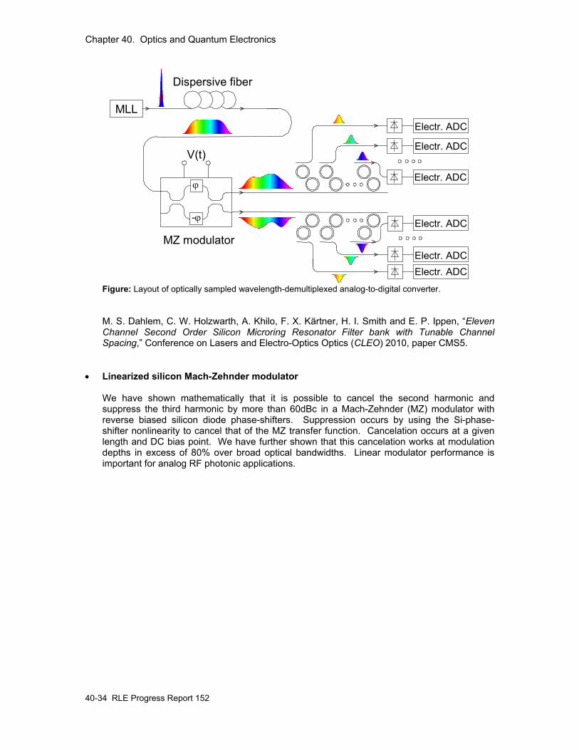
Chapter 40. Optics and Quantum Electronics
40-34 RLE Progress Report 152
Electr. ADC
MLL
MZ modulator
V(t)
Dispersive fiber
Electr. ADC
Electr. ADC
Electr. ADC
Electr. ADCElectr. ADC
ϕ
-ϕ
Figure: Layout of optically sampled wavelength-demultiplexed analog-to-digital converter. M. S. Dahlem, C. W. Holzwarth, A. Khilo, F. X. Kärtner, H. I. Smith and E. P. Ippen, “Eleven Channel Second Order Silicon Microring Resonator Filter bank with Tunable Channel Spacing,” Conference on Lasers and Electro-Optics Optics (CLEO) 2010, paper CMS5.
• Linearized silicon Mach-Zehnder modulator We have shown mathematically that it is possible to cancel the second harmonic and suppress the third harmonic by more than 60dBc in a Mach-Zehnder (MZ) modulator with reverse biased silicon diode phase-shifters. Suppression occurs by using the Si-phase-shifter nonlinearity to cancel that of the MZ transfer function. Cancelation occurs at a given length and DC bias point. We have further shown that this cancelation works at modulation depths in excess of 80% over broad optical bandwidths. Linear modulator performance is important for analog RF photonic applications.
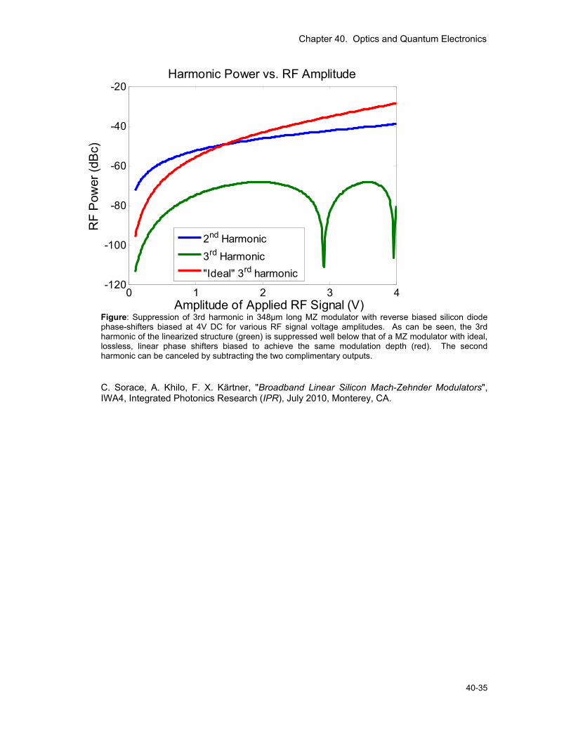
Chapter 40. Optics and Quantum Electronics
40-35
0 1 2 3 4-120
-100
-80
-60
-40
-20
Amplitude of Applied RF Signal (V)
RF
Pow
er (d
Bc)
Harmonic Power vs. RF Amplitude
2nd Harmonic3rd Harmonic "Ideal" 3rd harmonic
Figure: Suppression of 3rd harmonic in 348μm long MZ modulator with reverse biased silicon diode phase-shifters biased at 4V DC for various RF signal voltage amplitudes. As can be seen, the 3rd harmonic of the linearized structure (green) is suppressed well below that of a MZ modulator with ideal, lossless, linear phase shifters biased to achieve the same modulation depth (red). The second harmonic can be canceled by subtracting the two complimentary outputs. C. Sorace, A. Khilo, F. X. Kärtner, "Broadband Linear Silicon Mach-Zehnder Modulators", IWA4, Integrated Photonics Research (IPR), July 2010, Monterey, CA.
Chapter 40. Optics and Quantum Electronics
40-36 RLE Progress Report 152
5. Attosecond Resolution Timing Jitter Characterization of Cr:LiSAF Lasers Sponsors National Science Foundation – ECS-0900901 Air Force Office of Scientific Research – FA9550-07-1-0014 and FA9550-07-1-0101 Project Staff Umit Demirbas, Andrew Benedick, Duo Li, Jungwon Kim, Prof. Alphan Sennaroglu, Prof. James G. Fujimoto, and Prof. Franz X. Kärtner The development of stabilized femtosecond sources for applications in ultralow timing jitter pulse train generation and ultralow phase noise microwave generation would constitute a major advance in high speed, high resolution data processing, microwave generation and metrology. Improvements in jitter offer the potential of unprecedented sampling rates for high resolution ADCs. Stabilized mode-locked lasers can provide optical pulse streams with ultralow timing jitter, which may be converted to ultralow phase noise microwave signals. The fundamental limit of timing jitter in modelocked lasers comes from spontaneous emission noise. In theory, timing jitter power spectral density is proportional to pulse width squared and inversely proportional to intracavity pulse energy and cavity photon lifetime. Hence, it is desirable to use mode-locked lasers which have broad gain bandwidths to support femtosecond pulses, as well as resonators with low output coupling which support higher intracavity pulse energies with long cavity decay times. In addition, the system should be compact, in order to facilitate isolation from environmental fluctuations and practical applications. Therefore, broadband gain media which can be directly diode pumped are of particular importance in the development of femtosecond oscillators. The Cr:Colquiriite lasers could out-perform semiconductors lasers, fiber lasers and Ti:Sapphire lasers in terms of these requirements. For typical solid-sate mode-locked lasers, theoretical analysis predicts a timing jitter in the attosecond regime at frequencies above ∼10 kHz [1, 2]. However, it remained challenging to achieve sub-10-fs resolution in a timing jitter measurement until the invention of balanced nonlinear optical intensity cross correlation [3, 4]. Balanced nonlinear optical cross correlation has high timing sensitivity, wide detection range and cancels excess photodetection noise, enabling highly sensitive measurements of timing jitter. Recent accomplishments: • Attosecond Resolution Timing Jitter Characterization of Cr:LiSAF Lasers
Figure 1 shows the schematic of the timing jitter noise measurement. Two custom-built, diode-pumped, SBR mode-locked Cr:LiSAF lasers operating at 100 MHz repetition rate were synchronized using a nonlinear optical cross correlator in a low-bandwidth (∼1 kHz) phase-locked loop (PLL) configuration. The combined laser output is sent to the first dichroic mirror of the cross correlator, which focuses the beams inside a 400 μm thick type-II phase matching optimized BBO crystal for 850 nm. The second harmonic generated in the forward pass is transmitted through the second dichroic mirror and then directed to the first photodiode of the balanced detector. The returning beams (at the fundamental) are focused back in to the nonlinear crystal, where the second harmonic is generated and detected by the second photodiode of the balanced detector. The signal from the balanced detector is proportional to the timing delay between the two pulses. The cross correlator signal at low frequencies is also used as the error signal for the PLL, which synchronizes the lasers by actuating a small PZT in one of the lasers. Once the lasers are synchronized with the low-bandwidth PLL, the signal in the high frequency range is directly proportional to the relative timing jitter of the free running lasers, which is uncorrelated. The balanced nonlinear optical cross correlator provides a measurement resolution of ∼2x10⁻¹⁰ fs2/Hz at 100 kHz (-195 dBc at 1 GHz carrier).
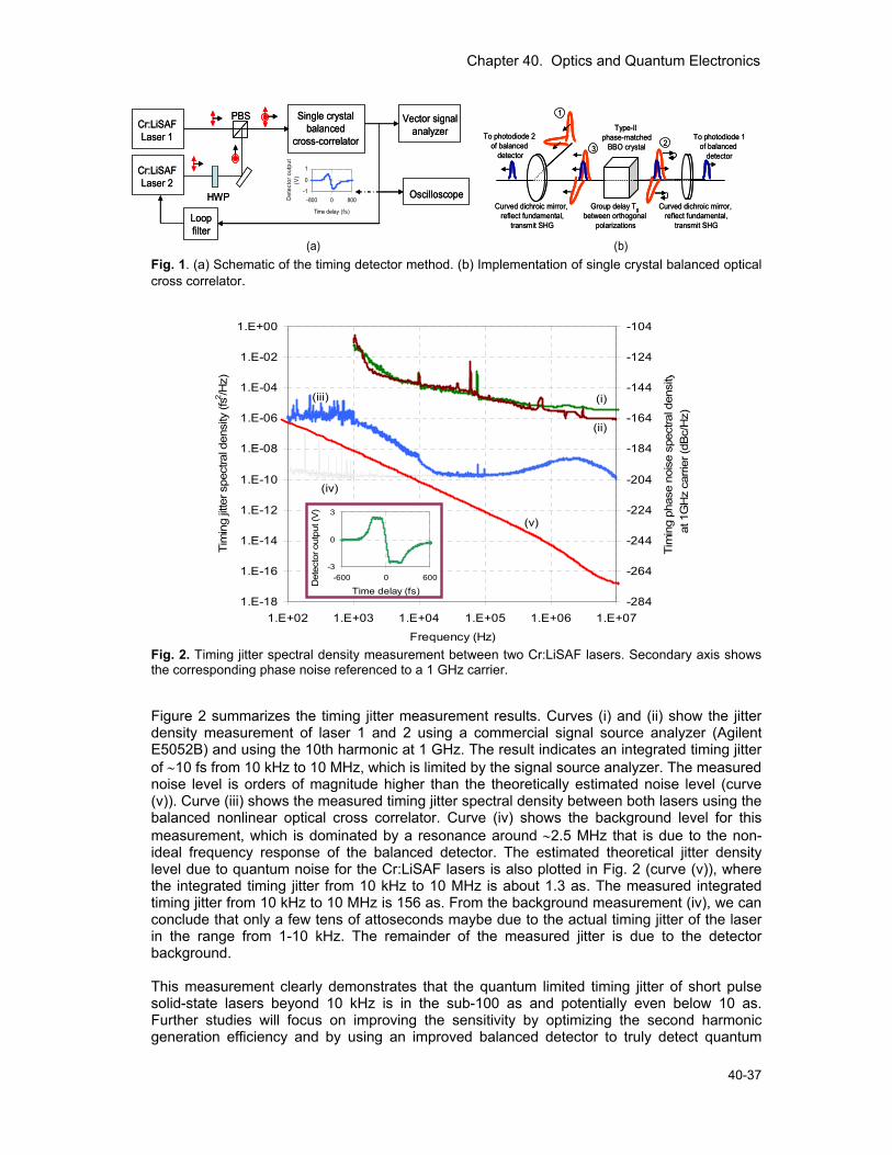
Chapter 40. Optics and Quantum Electronics
40-37
Cr:LiSAFLaser 1
Cr:LiSAFLaser 2
HWP
PBS Single crystal balanced
cross-correlator
Loop filter
Oscilloscope
Vector signal analyzer
-1
0
1
-800 0 800
Time delay (fs)
Det
ecto
r out
put
(V)
Cr:LiSAFLaser 1
Cr:LiSAFLaser 2
HWP
PBS Single crystal balanced
cross-correlator
Loop filter
Oscilloscope
Vector signal analyzer
-1
0
1
-800 0 800
Time delay (fs)
Det
ecto
r out
put
(V)
Type-II phase-matched
BBO crystal
Curved dichroic mirror, reflect fundamental,
transmit SHG
To photodiode 1of balanced
detector
To photodiode 2of balanced
detector
1
32
Group delay Tgbetween orthogonal
polarizations
Curved dichroic mirror, reflect fundamental,
transmit SHG
Type-II phase-matched
BBO crystal
Curved dichroic mirror, reflect fundamental,
transmit SHG
To photodiode 1of balanced
detector
To photodiode 2of balanced
detector
1
32
Group delay Tgbetween orthogonal
polarizations
Curved dichroic mirror, reflect fundamental,
transmit SHG
(a) (b) Fig. 1. (a) Schematic of the timing detector method. (b) Implementation of single crystal balanced optical cross correlator.
1.E-18
1.E-16
1.E-14
1.E-12
1.E-10
1.E-08
1.E-06
1.E-04
1.E-02
1.E+00
1.E+02 1.E+03 1.E+04 1.E+05 1.E+06 1.E+07
Frequency (Hz)
Tim
ing
jitte
r spe
ctra
l den
sity
(fs2 /H
z)
-284
-264
-244
-224
-204
-184
-164
-144
-124
-104
Tim
ing
phas
e no
ise
spec
tral d
ensi
tyat
1G
Hz
carri
er (d
Bc/
Hz)
_ - (i)
(ii)
(iii)
(iv)
(v)
-3
0
3
-600 0 600
Time delay (fs)
Det
ecto
r out
put (
V)
Fig. 2. Timing jitter spectral density measurement between two Cr:LiSAF lasers. Secondary axis shows the corresponding phase noise referenced to a 1 GHz carrier. Figure 2 summarizes the timing jitter measurement results. Curves (i) and (ii) show the jitter density measurement of laser 1 and 2 using a commercial signal source analyzer (Agilent E5052B) and using the 10th harmonic at 1 GHz. The result indicates an integrated timing jitter of ∼10 fs from 10 kHz to 10 MHz, which is limited by the signal source analyzer. The measured noise level is orders of magnitude higher than the theoretically estimated noise level (curve (v)). Curve (iii) shows the measured timing jitter spectral density between both lasers using the balanced nonlinear optical cross correlator. Curve (iv) shows the background level for this measurement, which is dominated by a resonance around ∼2.5 MHz that is due to the non-ideal frequency response of the balanced detector. The estimated theoretical jitter density level due to quantum noise for the Cr:LiSAF lasers is also plotted in Fig. 2 (curve (v)), where the integrated timing jitter from 10 kHz to 10 MHz is about 1.3 as. The measured integrated timing jitter from 10 kHz to 10 MHz is 156 as. From the background measurement (iv), we can conclude that only a few tens of attoseconds maybe due to the actual timing jitter of the laser in the range from 1-10 kHz. The remainder of the measured jitter is due to the detector background. This measurement clearly demonstrates that the quantum limited timing jitter of short pulse solid-state lasers beyond 10 kHz is in the sub-100 as and potentially even below 10 as. Further studies will focus on improving the sensitivity by optimizing the second harmonic generation efficiency and by using an improved balanced detector to truly detect quantum
Chapter 40. Optics and Quantum Electronics
40-38 RLE Progress Report 152
limited performance. To the best of our knowledge, this is the lowest reported value of timing jitter for any mode-locked solid-state laser, and demonstrates the inherently low noise character of mode-locked lasers at high frequencies. This study shows the potential of low-cost femtosecond Cr:LiSAF laser systems as ultra-low timing jitter sources, and the advantage of the balanced optical cross correlation for timing jitter measurements. D. Umit, B. Andrew, S. Alphan, L. Duo, K. Jungwon, G. F. James, and X. K. Franz, "Attosecond Resolution Timing Jitter Characterization of Diode Pumped Femtosecond Cr:LiSAF Lasers," in Conference on Lasers and Electro-Optics, San Jose, CA, 2010, p. CTuDD6.
6. Ultrafast Phenomena and Quantum Electronics Sponsors Air Force Office of Scientific Research FA9550-10-1-0063 Project Staff Vasileios-Marios Gkortsas, Dr. Hyunyong Choi, Dr. Laurent Diehl, Dr. David Bour, Dr. Scott Corzine, Dr. Jintian Zhu, Dr. Gloria Höfler, Prof. Federico Capasso, Prof. Theodore B. Norris, and Prof. Franz X. Kärtner • Coherent Pulse Propagation in QCLs In the coherent light-matter interaction regime, a pulse propagating through an absorber with area on the order of π leads to coherent oscillations of the population, often called Rabi flopping, leading to the McCall-Hahn area theorem. However, in a semiconductor laser, this effect is extremely weak and difficult to observe due to the largely prevailing dephasing processes. On the other hand, Rabi flopping is possible in QCLs because semiconductor intersubband transitions afford the possibility of obtaining very large dipole transition matrix elements. In our work we have investigated pulse propagation in the time domain, and have directly observed the Rabi oscillations in the QCL gain medium under lasing conditions. We have modeled the dynamic interaction between the QCL and the ultrashort pulse by three-level Maxwell-Bloch equations. The three-level model describes the essential physics of the QCL that includes the populated lasing state (level 3), the depopulated lasing state (level 2) and the extracted ground state (level 1). The central observation is the contribution of the coherent dynamics between the propagating resonant optical pulse and the density-dipole oscillation in the QCL. We have monitored both the propagated mid-IR pulse through the QCL and the transient changes of the lasing dynamics for three different pulse areas Θ. For the envelopes of the propagated pulses (Fig. a-c), noticeable features are the dramatic advance of the peak envelope to earlier times and significant reshaping as Θ increases. For the lasing dynamics (Fig. g), the magnitude of the laser output transient decreases after the pulse by as much as 59% (compared to the lasing intensity before the pulse) when Θ is π (black curve), and it further decreases to about 64% when Θ reaches 2π (red curve). However, when Θ approaches 3π, the transient dynamics is weakly visible, showing no significant saturation of the lasing intensity (blue curve). The envelope reshaping of the propagated pulse (Fig. d-f) and the lasing dynamics (Fig. h) agree well with the experiments. Simulated density and dipole polarization (not shown) reveal that the Rabi oscillation frequency ΩR becomes larger than the dephasing rate as increasing Θ. In this regime, the dipole polarization is coherently cycled due to Rabi flopping, and resulting in the time
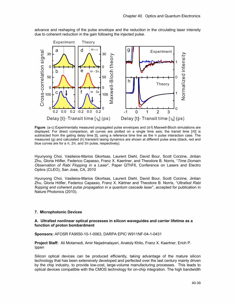
Chapter 40. Optics and Quantum Electronics
40-39
advance and reshaping of the pulse envelope and the reduction in the circulating laser intensity due to coherent reduction in the gain following the injected pulse.
Figure: (a-c) Experimentally measured propagated pulse envelopes and (d-f) Maxwell-Bloch simulations are displayed. For direct comparison, all curves are plotted on a single time axis; the transit time [τ0] is subtracted from the gating delay time [t], using a reference time line as the π pulse interaction case. The measured (g) and calculated (h) transient lasing dynamics are shown at different pulse area (black, red and blue curves are for a π, 2π, and 3π pulse, respectively). Hyunyong Choi, Vasileios-Marios Gkortsas, Laurent Diehl, David Bour, Scott Corzine, Jintian Zhu, Gloria Höfler, Federico Capasso, Franz X. Kaertner, and Theodore B. Norris, “Time Domain Observation of Rabi Flopping in a Laser”, Paper QThF6, Conference on Lasers and Electro Optics (CLEO), San Jose, CA, 2010 Hyunyong Choi, Vasileios-Marios Gkortsas, Laurent Diehl, David Bour, Scott Corzine, Jintian Zhu, Gloria Höfler, Federico Capasso, Franz X. Kärtner and Theodore B. Norris, “Ultrafast Rabi flopping and coherent pulse propagation in a quantum cascade laser”, accepted for publication in Nature Photonics (2010). 7. Microphotonic Devices A. Ultrafast nonlinear optical processes in silicon waveguides and carrier lifetime as a function of proton bombardment Sponsors: AFOSR FA9550-10-1-0063, DARPA EPIC W911NF-04-1-0431 Project Staff: Ali Motamedi, Amir Nejadmalayeri, Anatoly Khilo, Franz X. Kaertner, Erich P. Ippen Silicon optical devices can be produced efficiently, taking advantage of the mature silicon technology that has been extensively developed and perfected over the last century mainly driven by the chip industry, to provide low-cost, large-volume manufacturing processes. This leads to optical devices compatible with the CMOS technology for on-chip integration. The high bandwidth
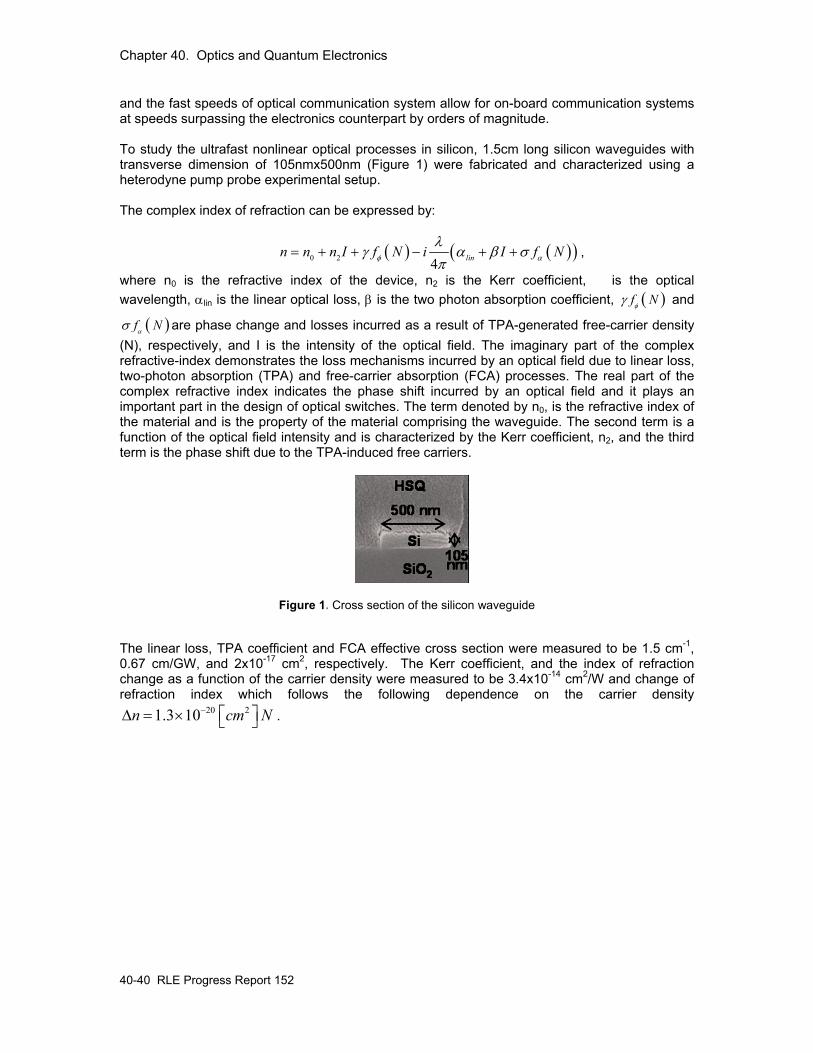
Chapter 40. Optics and Quantum Electronics
40-40 RLE Progress Report 152
and the fast speeds of optical communication system allow for on-board communication systems at speeds surpassing the electronics counterpart by orders of magnitude. To study the ultrafast nonlinear optical processes in silicon, 1.5cm long silicon waveguides with transverse dimension of 105nmx500nm (Figure 1) were fabricated and characterized using a heterodyne pump probe experimental setup. The complex index of refraction can be expressed by:
( ) ( )( )0 2 4 linn n n I f N i I f Nφ α
λγ α β σ
π= + + − + + ,
where n0 is the refractive index of the device, n2 is the Kerr coefficient, is the optical wavelength, αlin is the linear optical loss, β is the two photon absorption coefficient, ( )f Nφγ and
( )f Nασ are phase change and losses incurred as a result of TPA-generated free-carrier density (N), respectively, and I is the intensity of the optical field. The imaginary part of the complex refractive-index demonstrates the loss mechanisms incurred by an optical field due to linear loss, two-photon absorption (TPA) and free-carrier absorption (FCA) processes. The real part of the complex refractive index indicates the phase shift incurred by an optical field and it plays an important part in the design of optical switches. The term denoted by n0, is the refractive index of the material and is the property of the material comprising the waveguide. The second term is a function of the optical field intensity and is characterized by the Kerr coefficient, n2, and the third term is the phase shift due to the TPA-induced free carriers.
Figure 1. Cross section of the silicon waveguide
The linear loss, TPA coefficient and FCA effective cross section were measured to be 1.5 cm-1, 0.67 cm/GW, and 2x10-17 cm2, respectively. The Kerr coefficient, and the index of refraction change as a function of the carrier density were measured to be 3.4x10⁻¹⁴ cm2/W and change of refraction index which follows the following dependence on the carrier density
20 21.3 10n cm N− ⎡ ⎤Δ = × ⎣ ⎦ .
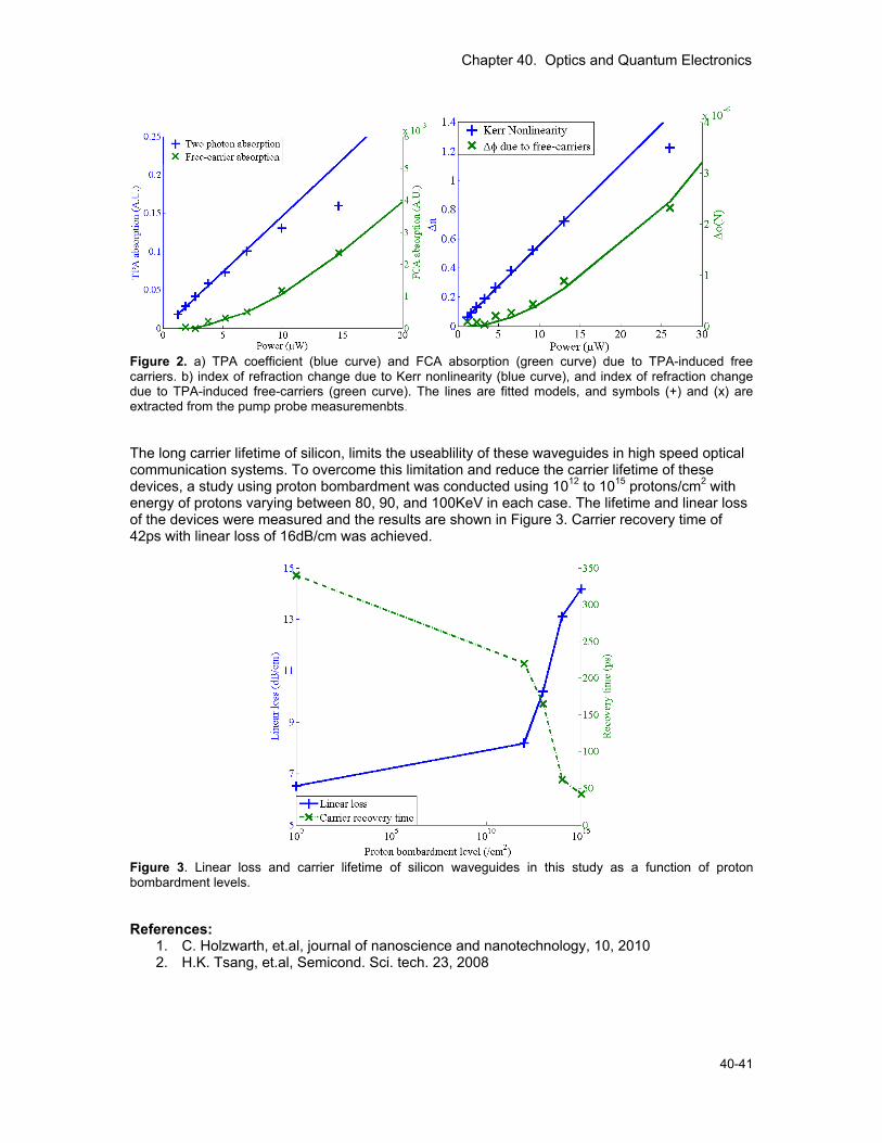
Chapter 40. Optics and Quantum Electronics
40-41
Figure 2. a) TPA coefficient (blue curve) and FCA absorption (green curve) due to TPA-induced free carriers. b) index of refraction change due to Kerr nonlinearity (blue curve), and index of refraction change due to TPA-induced free-carriers (green curve). The lines are fitted models, and symbols (+) and (x) are extracted from the pump probe measuremenbts.
The long carrier lifetime of silicon, limits the useablility of these waveguides in high speed optical communication systems. To overcome this limitation and reduce the carrier lifetime of these devices, a study using proton bombardment was conducted using 1012 to 1015 protons/cm2 with energy of protons varying between 80, 90, and 100KeV in each case. The lifetime and linear loss of the devices were measured and the results are shown in Figure 3. Carrier recovery time of 42ps with linear loss of 16dB/cm was achieved.
Figure 3. Linear loss and carrier lifetime of silicon waveguides in this study as a function of proton bombardment levels.
References:
1. C. Holzwarth, et.al, journal of nanoscience and nanotechnology, 10, 2010 2. H.K. Tsang, et.al, Semicond. Sci. tech. 23, 2008
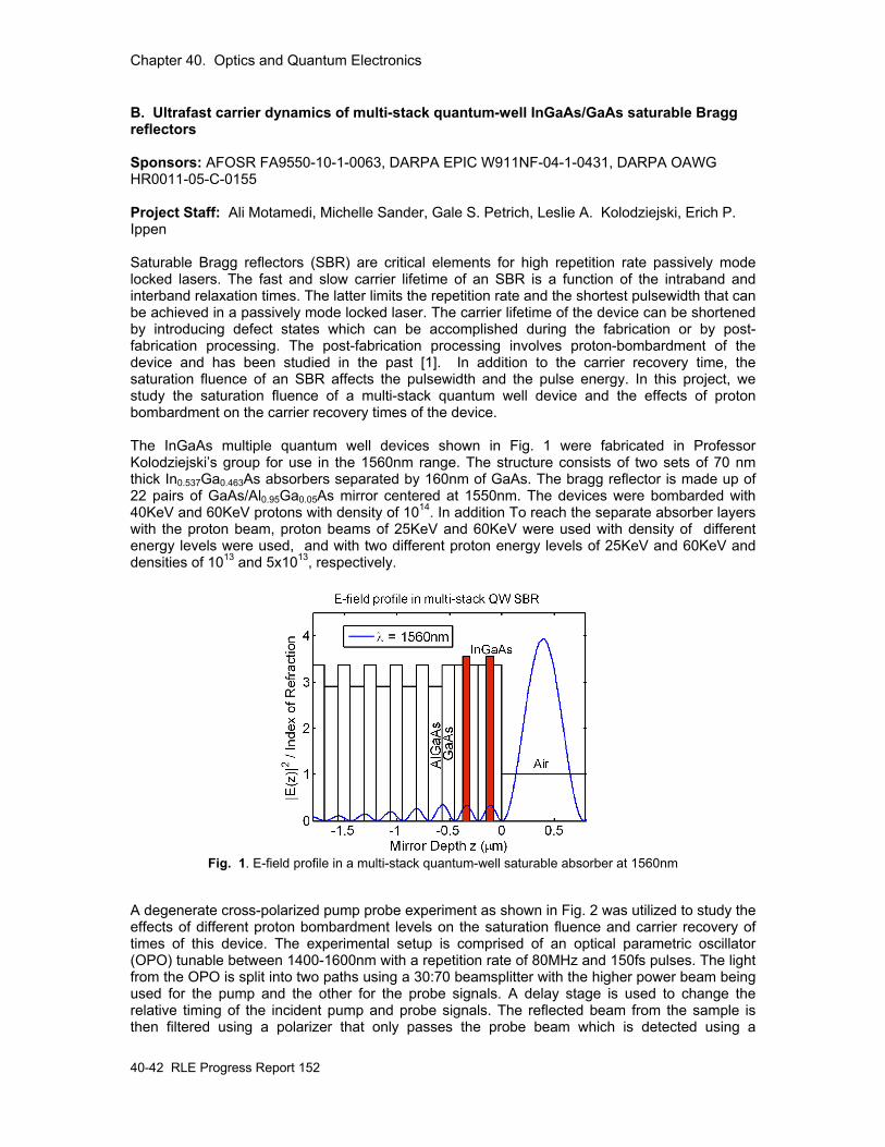
Chapter 40. Optics and Quantum Electronics
40-42 RLE Progress Report 152
B. Ultrafast carrier dynamics of multi-stack quantum-well InGaAs/GaAs saturable Bragg reflectors Sponsors: AFOSR FA9550-10-1-0063, DARPA EPIC W911NF-04-1-0431, DARPA OAWG HR0011-05-C-0155 Project Staff: Ali Motamedi, Michelle Sander, Gale S. Petrich, Leslie A. Kolodziejski, Erich P. Ippen Saturable Bragg reflectors (SBR) are critical elements for high repetition rate passively mode locked lasers. The fast and slow carrier lifetime of an SBR is a function of the intraband and interband relaxation times. The latter limits the repetition rate and the shortest pulsewidth that can be achieved in a passively mode locked laser. The carrier lifetime of the device can be shortened by introducing defect states which can be accomplished during the fabrication or by post-fabrication processing. The post-fabrication processing involves proton-bombardment of the device and has been studied in the past [1]. In addition to the carrier recovery time, the saturation fluence of an SBR affects the pulsewidth and the pulse energy. In this project, we study the saturation fluence of a multi-stack quantum well device and the effects of proton bombardment on the carrier recovery times of the device. The InGaAs multiple quantum well devices shown in Fig. 1 were fabricated in Professor Kolodziejski’s group for use in the 1560nm range. The structure consists of two sets of 70 nm thick In0.537Ga0.463As absorbers separated by 160nm of GaAs. The bragg reflector is made up of 22 pairs of GaAs/Al0.95Ga0.05As mirror centered at 1550nm. The devices were bombarded with 40KeV and 60KeV protons with density of 1014. In addition To reach the separate absorber layers with the proton beam, proton beams of 25KeV and 60KeV were used with density of different energy levels were used, and with two different proton energy levels of 25KeV and 60KeV and densities of 1013 and 5x10¹³, respectively.
Fig. 1. E-field profile in a multi-stack quantum-well saturable absorber at 1560nm
A degenerate cross-polarized pump probe experiment as shown in Fig. 2 was utilized to study the effects of different proton bombardment levels on the saturation fluence and carrier recovery of times of this device. The experimental setup is comprised of an optical parametric oscillator (OPO) tunable between 1400-1600nm with a repetition rate of 80MHz and 150fs pulses. The light from the OPO is split into two paths using a 30:70 beamsplitter with the higher power beam being used for the pump and the other for the probe signals. A delay stage is used to change the relative timing of the incident pump and probe signals. The reflected beam from the sample is then filtered using a polarizer that only passes the probe beam which is detected using a
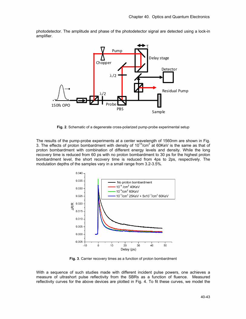
Chapter 40. Optics and Quantum Electronics
40-43
photodetector. The amplitude and phase of the photodetector signal are detected using a lock-in amplifier.
Fig. 2. Schematic of a degenerate cross-polarized pump-probe experimental setup The results of the pump-probe experiments at a center wavelength of 1560nm are shown in Fig. 3. The effects of proton bombardment with density of 1014/cm2 at 60KeV is the same as that of proton bombardment with combination of different energy levels and density. While the long recovery time is reduced from 60 ps with no proton bombardment to 30 ps for the highest proton bombardment level, the short recovery time is reduced from 4ps to 2ps, respectively. The modulation depths of the samples vary in a small range from 3.2-3.5%.
Fig. 3. Carrier recovery times as a function of proton bombardment With a sequence of such studies made with different incident pulse powers, one achieves a measure of ultrashort pulse reflectivity from the SBRs as a function of fluence. Measured reflectivity curves for the above devices are plotted in Fig. 4. To fit these curves, we model the
Delay stage
150fs OPO
Sample
Residual Pump λ/2
λ/2
Chopper
τ Pump
Detector
ProbePBS
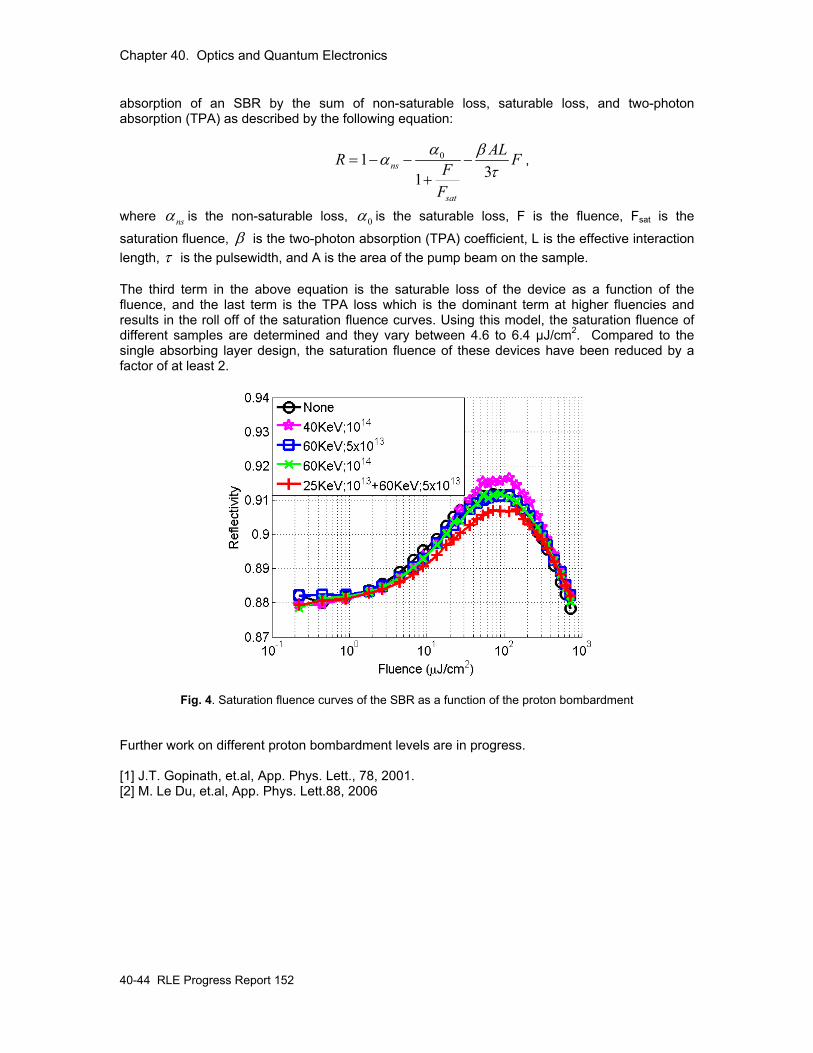
Chapter 40. Optics and Quantum Electronics
40-44 RLE Progress Report 152
absorption of an SBR by the sum of non-saturable loss, saturable loss, and two-photon absorption (TPA) as described by the following equation:
0131
ns
sat
ALR FFF
α βατ
= − − −+
,
where nsα is the non-saturable loss, 0α is the saturable loss, F is the fluence, Fsat is the
saturation fluence, β is the two-photon absorption (TPA) coefficient, L is the effective interaction length, τ is the pulsewidth, and A is the area of the pump beam on the sample. The third term in the above equation is the saturable loss of the device as a function of the fluence, and the last term is the TPA loss which is the dominant term at higher fluencies and results in the roll off of the saturation fluence curves. Using this model, the saturation fluence of different samples are determined and they vary between 4.6 to 6.4 µJ/cm2. Compared to the single absorbing layer design, the saturation fluence of these devices have been reduced by a factor of at least 2.
Fig. 4. Saturation fluence curves of the SBR as a function of the proton bombardment Further work on different proton bombardment levels are in progress. [1] J.T. Gopinath, et.al, App. Phys. Lett., 78, 2001. [2] M. Le Du, et.al, App. Phys. Lett.88, 2006
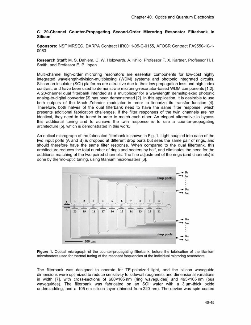
Chapter 40. Optics and Quantum Electronics
40-45
C. 20-Channel Counter-Propagating Second-Order Microring Resonator Filterbank in Silicon Sponsors: NSF MRSEC, DARPA Contract HR0011-05-C-0155, AFOSR Contract FA9550-10-1-0063 Research Staff: M. S. Dahlem, C. W. Holzwarth, A. Khilo, Professor F. X. Kärtner, Professor H. I. Smith, and Professor E. P. Ippen Multi-channel high-order microring resonators are essential components for low-cost highly integrated wavelength-division-multiplexing (WDM) systems and photonic integrated circuits. Silicon-on-insulator (SOI) platforms are attractive due to their low propagation loss and high index contrast, and have been used to demonstrate microring-resonator-based WDM components [1,2]. A 20-channel dual filterbank intended as a multiplexer for a wavelength demultiplexed photonic analog-to-digital converter [3] has been demonstrated [2]. In this application, it is desirable to use both outputs of the Mach Zehnder modulator in order to linearize its transfer function [4]. Therefore, both halves of the dual filterbank need to have the same filter response, which presents additional fabrication challenges. If the filter responses of the twin channels are not identical, they need to be tuned in order to match each other. An elegant alternative to bypass this additional tuning and to achieve the twin response is to use a counter-propagating architecture [5], which is demonstrated in this work. An optical micrograph of the fabricated filterbank is shown in Fig. 1. Light coupled into each of the two input ports (A and B) is dropped at different drop ports but sees the same pair of rings, and should therefore have the same filter response. When compared to the dual filterbank, this architecture reduces the total number of rings and heaters by half, and eliminates the need for the additional matching of the two paired channels. The fine adjustment of the rings (and channels) is done by thermo-optic tuning, using titanium microheaters [6].
200 μm
drop ports
drop ports
A
B
1 2 3 4 5 6 7 8 9 10
20 19 18 17 16 15 14 13 12 11
. . . . .
A1 B1
A10 B10
A20 B20
A11 B11 . . . . .
Figure 1. Optical micrograph of the counter-propagating filterbank, before the fabrication of the titanium microheaters used for thermal tuning of the resonant frequencies of the individual microring resonators. The filterbank was designed to operate for TE-polarized light, and the silicon waveguide dimensions were optimized to reduce sensitivity to sidewall roughness and dimensional variations in width [7], with cross-sections of 600×105 nm (ring waveguides) and 495×105 nm (bus waveguides). The filterbank was fabricated on an SOI wafer with a 3 μm-thick oxide undercladding, and a 105 nm silicon layer (thinned from 220 nm). The device was spin coated
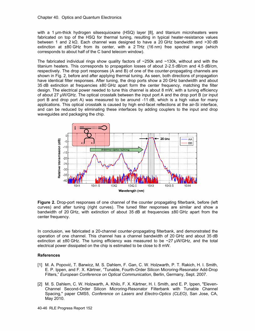
Chapter 40. Optics and Quantum Electronics
40-46 RLE Progress Report 152
with a 1 μm-thick hydrogen silsesquioxane (HSQ) layer [8], and titanium microheaters were fabricated on top of the HSQ for thermal tuning, resulting in typical heater-resistance values between 1 and 2 kΩ. Each channel was designed to have a 20 GHz bandwidth and >30 dB extinction at ±80 GHz from its center, with a 2 THz (16 nm) free spectral range (which corresponds to about half of the C band telecom window). The fabricated individual rings show quality factors of ~250k and ~130k, without and with the titanium heaters. This corresponds to propagation losses of about 2-2.5 dB/cm and 4.5 dB/cm, respectively. The drop port responses (A and B) of one of the counter-propagating channels are shown in Fig. 2, before and after applying thermal tuning. As seen, both directions of propagation have identical filter responses. After tuning, the drop ports show a 20 GHz bandwidth and about 35 dB extinction at frequencies ±80 GHz apart form the center frequency, matching the filter design. The electrical power needed to tune this channel is about 8 mW, with a tuning efficiency of about 27 μW/GHz. The optical crosstalk between the input port A and the drop port B (or input port B and drop port A) was measured to be around -11 dB, which is a high value for many applications. This optical crosstalk is caused by high end-facet reflections at the air-Si interface, and can be reduced by eliminating these interfaces by adding couplers to the input and drop waveguides and packaging the chip.
Figure 2. Drop-port responses of one channel of the counter propagating filterbank, before (left curves) and after tuning (right curves). The tuned filter responses are similar and show a bandwidth of 20 GHz, with extinction of about 35 dB at frequencies ±80 GHz apart from the center frequency. In conclusion, we fabricated a 20-channel counter-propagating filterbank, and demonstrated the operation of one channel. This channel has a channel bandwidth of 20 GHz and about 35 dB extinction at ±80 GHz. The tuning efficiency was measured to be ~27 μW/GHz, and the total electrical power dissipated on the chip is estimated to be close to 8 mW. References [1] M. A. Popović, T. Barwicz, M. S. Dahlem, F. Gan, C. W. Holzwarth, P. T. Rakich, H. I. Smith,
E. P. Ippen, and F. X. Kärtner, “Tunable, Fourth-Order Silicon Microring-Resonator Add-Drop Filters,” European Conference on Optical Communication, Berlin, Germany, Sept. 2007.
[2] M. S. Dahlem, C. W. Holzwarth, A. Khilo, F. X. Kärtner, H. I. Smith, and E. P. Ippen, "Eleven-
Channel Second-Order Silicon Microring-Resonator Filterbank with Tunable Channel Spacing," paper CMS5, Conference on Lasers and Electro-Optics (CLEO), San Jose, CA, May 2010.
Chapter 40. Optics and Quantum Electronics
40-47
[3] F. X. Kärtner, R. Amataya, M. Aranghini, H. Byun, J. Chen, M. Dahlem, N.A. DiLello, F. Gan,
C. W. Holzwarth, J. L. Hoyt, E. P. Ippen, A. Khilo, J. Kim, A. Motamedi, J. S. Orcutt, M. Park, M. Perrott, M. A. Popović, R. J. Ram, H. I. Smith, G. R. Zhou, S. J. Spector, T. M. Lyszczarz, M. W. Geis, D. M. Lennon, J. U. Yoon, M. E. Grein, and R. T. Schulein, “Photonic Analog to Digital Conversion with Electronic-Photonic Integrated Circuits”, SPIE Photonics West Conference, San Jose, CA, January 2008.
[4] J. C. Twichell and R. Helkey, "Phase-encoded optical sampling for analog-to-digital
converters," IEEE Photon. Technol. Lett., vol. 12, pp. 1237-1239 (2000). [5] C. W. Holzwarth, A. Khilo, M. Dahlem, M. A. Popovic, F. X. Kärtner, E. P. Ippen, and H. I.
Smith, "Device Architecture and Precision Nanofabrication of Microring-Resonator Filter Banks for Integrated Photonic Systems," J. Nanosci. Nanotechnol., vol. 10, pp. 2044-2052 (2010).
[6] F. Gan, T. Barwicz, M. A. Popović, M. S. Dahlem, C. W. Holzwarth, P. T. Rakich, H. I. Smith,
E. P. Ippen, and F. X. Kärtner, “Maximizing the Thermo-Optic Tuning Range of Silicon Photonic Structures,” TuB3.3, IEEE/LEOS Photonics in Switching 2007 Conference, San Francisco, CA, August 2007.
[7] M. A. Popović, T. Barwicz, E. P. Ippen and F. X. Kärtner, “Global Design Rules for Silicon
Microphotonic Waveguides: Sensitivity, Polarization and Resonance Tunability,” paper CTuCC1, Conference on Lasers and Electro Optics (CLEO), Long Beach, CA, May 2006.
[8] C. W. Holzwarth, T. Barwicz, and H. I. Smith, “Optimization of Hydrogen Silsesquioxane for
Photonic Applications,” J. Vac. Sci. & Technol. B, vol. 25, pp. 2658-2661 (2007). D. Dynamical Slow Light Cell based on Controlled Far-Field Interference of Microring Resonators Sponsors: NSF MRSEC, AFOSR Contract FA9550-10-1-0063 Research Staff: M. S. Dahlem, M. A. Popović, C. W. Holzwarth, Professor H. I. Smith, and Professor E. P. Ippen “Slow light” (i.e. resonance-based propagation delay) photonic devices are interesting structures to build such components, due to the resonantly enhanced group delay of the propagating light [1]. The use of resonant structures also results in small devices, which can easily be integrated with electronics and tuned [2]. Coupled microring resonators have been extensively used to build slow light devices [3-7]. In most common configurations, ring resonators are coupled directly in series [3-5], or in parallel, through a common bus [4-6]. All these are coupled through 2×2 directional couplers. Such arrangements usually mean the devices are synthesized from “reactive” coupling of cavities, i.e. from energy exchange between resonators. In this work, we demonstrate a dynamical slow light cell that makes use of “far-field” coupling, i.e. a form of coupling that involves no energy exchange between cavities, but rather affects their lifetime through destructive or constructive interference in the cavities’ radiation channel(s). The device here is based on a dual microring resonator configuration with a shared 3×3 coupler. Such a 3×3 coupled dual microring resonator configuration has also been propose for use as a loadable and erasable optical memory unit, using active microring optical integrators [7]. In our device, the group delay is controlled by thermo-optically detuning the resonant frequencies of the two rings from each other with titanium microheaters. In the lossless case, for a zero detuning, there is a slow light state that decouples the ring system from the bus waveguide, corresponding to an infinite external quality factor (Qext). In the demonstrated device, group delays up to 24 ps are
Chapter 40. Optics and Quantum Electronics
40-48 RLE Progress Report 152
measured, with losses <1 dB. By relaxing this condition and allowing larger losses, larger (and negative) group delays are observed, with a maximum group delay tuning range of 1 ns. Furthermore, in a device analogous to the one demonstrated here, fast detuning schemes such as optical pulse excitation or electronic carrier generation can be used to affect fast index changes to store light for an arbitrary time, limited only by the loss-limited cavity lifetime [6]. The interferometric dual-microring structure, illustrated in the inset of Fig. 1(c), was fabricated in a silicon-on-insulator (SOI) platform with a 3 μm-thick oxide undercladding, from the 105 nm top silicon layer (thinned down from 220 nm), and was then coated with a 1 μm-thick hydrogen silsesquioxane (HSQ) layer [8]. The cross sections of the ring and bus waveguides are 600×105 nm and 495×105 nm, respectively. The rings’ outer diameter is 14 μm and the targeted ring bus gap is 240 nm, corresponding to about 10% power coupling. Two individual titanium microheaters were fabricated on top of the HSQ for thermo-optic tuning of the resonant frequency of each individual ring [2]. Typical heater-resistance values were between 1 and 2 kΩ. The detuning of the rings changes the group delay because it allows access to the otherwise symmetry-forbidden high-Q antisymmetric state. The individual rings of this design (and fabricated in this process) typically show intrinsic Q factors of ~250k and ~130k, without and with the titanium heaters. This corresponds to propagation losses of about 2-2.5 dB/cm and 4.5 dB/cm, respectively. The device was tested for wavelengths around 1.5 μm, and the thermal control was performed using a multi-channel digital-to-analog controller. The thermal tuning efficiency is ~28 μW/GHz/ring, and the relative tuning range tried in this experiment is ±4 mW, which corresponds to ±140 GHz. TE-polarized light is coupled into the bus waveguide using a high-NA lensed fiber, and the transmitted light is collected with a similar lensed fiber. The slow light cell response is measured using an optical vector analyzer which simultaneously provides the amplitude and phase response. The amplitude response and group delay are measured for different relative detunings between the two rings – Fig. 1(a)-(b). When the rings are widely detuned, the resonances are far apart and the system is equivalent to two all-pass filters with different resonant frequencies. The measured total (loaded) Q factors for the rings are ~5k and ~8k, which correspond to external Q factors of ~6k and ~9k. The splitting in the resonances around zero detuning is indication of residual direct coupling between the two ring modes (all the way across the waveguide), which here is an undesirable side-effect.
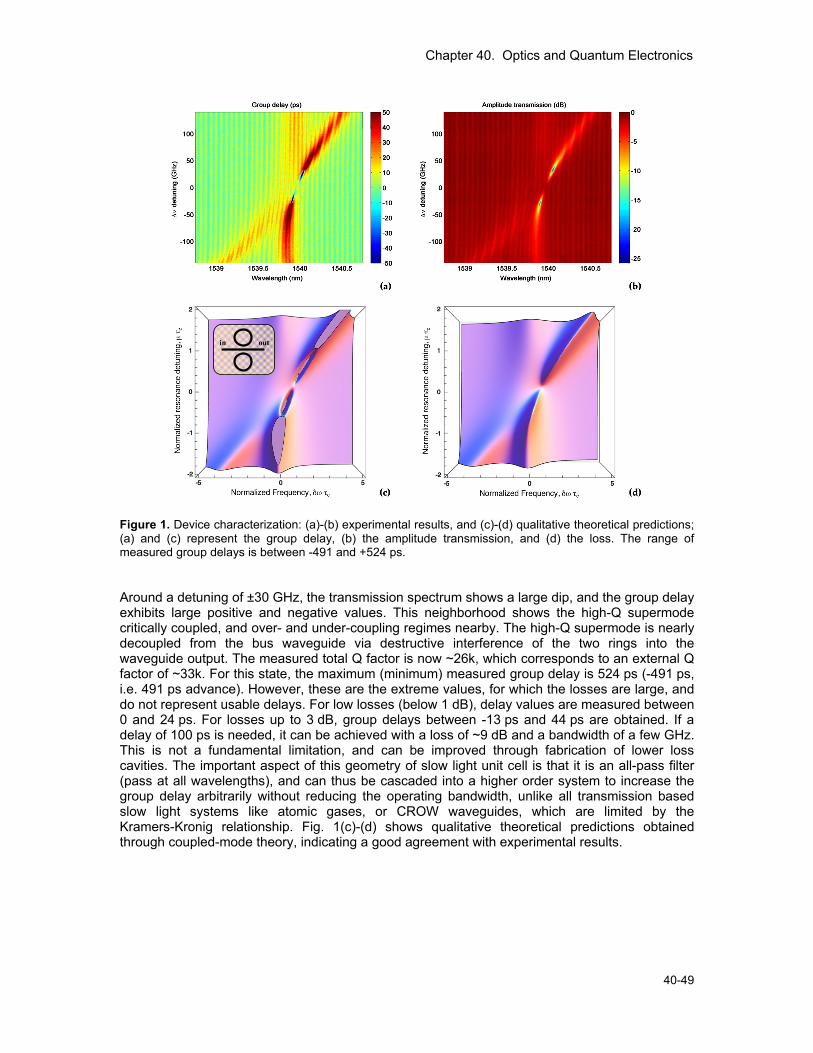
Chapter 40. Optics and Quantum Electronics
40-49
out in
Figure 1. Device characterization: (a)-(b) experimental results, and (c)-(d) qualitative theoretical predictions; (a) and (c) represent the group delay, (b) the amplitude transmission, and (d) the loss. The range of measured group delays is between -491 and +524 ps. Around a detuning of ±30 GHz, the transmission spectrum shows a large dip, and the group delay exhibits large positive and negative values. This neighborhood shows the high-Q supermode critically coupled, and over- and under-coupling regimes nearby. The high-Q supermode is nearly decoupled from the bus waveguide via destructive interference of the two rings into the waveguide output. The measured total Q factor is now ~26k, which corresponds to an external Q factor of ~33k. For this state, the maximum (minimum) measured group delay is 524 ps (-491 ps, i.e. 491 ps advance). However, these are the extreme values, for which the losses are large, and do not represent usable delays. For low losses (below 1 dB), delay values are measured between 0 and 24 ps. For losses up to 3 dB, group delays between -13 ps and 44 ps are obtained. If a delay of 100 ps is needed, it can be achieved with a loss of ~9 dB and a bandwidth of a few GHz. This is not a fundamental limitation, and can be improved through fabrication of lower loss cavities. The important aspect of this geometry of slow light unit cell is that it is an all-pass filter (pass at all wavelengths), and can thus be cascaded into a higher order system to increase the group delay arbitrarily without reducing the operating bandwidth, unlike all transmission based slow light systems like atomic gases, or CROW waveguides, which are limited by the Kramers-Kronig relationship. Fig. 1(c)-(d) shows qualitative theoretical predictions obtained through coupled-mode theory, indicating a good agreement with experimental results.
Chapter 40. Optics and Quantum Electronics
40-50 RLE Progress Report 152
References [1] T. F. Krauss, Nature Photonics, vol 2, pp. 448-450 (2008). [2] F. Gan, T. Barwicz, M. A. Popovic, M. S. Dahlem, C. W. Holzwarth, P. T. Rakich, H. I. Smith,
E. P. Ippen, and F. X. Kartner, Photonics in Switching, pp. 67-68 (2007). [3] J. Poon, L. Zhu, G. DeRose, and A. Yariv, Optics Letters, vol. 31, pp. 456-458 (2006). [4] J. B. Khurgin, Optics Letters, vol. 30, pp. 513-515 (2005). [5] F. N. Xia, L. Sekaric, and Y. Vlasov, Nature Photonics, vol. 1, pp. 65-71 (2007). [6] Q. F. Xu, P. Dong, and M. Lipson, Nature Physics, vol. 3, pp. 406-410 (2007). [7] Y. H. Ding, X. B. Zhang, X. L. Zhang, and D. X. Huang, Optics Communications, vol. 281, pp.
5315-5321 (2008). [8] C. W. Holzwarth, T. Barwicz, and H. I. Smith, Journal of Vacuum Science & Technology B,
vol. 25, pp. 2658-2661 (2007).