optimal design of spur gear by using rapid …
TRANSCRIPT
OPTIMAL DESIGN OF SPUR GEAR BY USING RAPID PROTOTYPING AND
REVERSE ENGINEERING
M.NAGARJUNA1, Dr. B. CHANDRA MOHANA REDDY2
1M.Tech, Product Design, JNTU college of engineering, Ananthapuramu, Andhra Pradesh, India
2Associate Professor of Mechanical Engineering, JNTU college of engineering, Ananthapuramu,
Andhra Pradesh, India
ABSTRACT
Reverse engineering helps in obtaining the
geometry part or product which is not available
otherwise. The aim of this project is to develop a
prototype model to optimize the design parameter
of spur gear (Alloy steel) face width changing
and to find the Allowable stresses to improve the
life time the of spur gear, it from physical model.
This physical model is scanned by using the 3D
scanner machine and obtained the STL file
format of manufactured component, this fileis
converted into CAD model and analyzed by using
solid works simulation tool. After analysis, a
prototype model is prepared by Fused Deposition
model(FDM)method.The material used to prepare
prototype is poly lactic acid(PLA). In thiswork,
five number of Face Widths are taken to observe
the Allowable stresses and compare with the
theoretical values. This entire process is involved
in Reverse Engineering.
Key words: Fused deposition model(FDM), Poly
lactic acid(PLA), solid works.
INTRODUCTION TO REVERSE
ENGINEERING
In today’s intensely competitive global
market, product enterprises are constantly
seeking new ways to shorten lead times for new
product developments that meet all customer
expectations. In general, product enterprise has
invested in CAD/CAM, rapid prototyping, and a
range of new technologies that provide business
benefits. Reverse engineering (RE) is now
considered one of the technologies that provide
business benefits in shortening the product
development cycle. Figure 1.1 below depicts
how RE allows the possibilities of closing the
loop between what is “as designed” and what is
“actually manufactured”.

Fig.1: Product development life cycle
WHAT IS REVERSE ENGINEERING?
Engineering is the process of designing,
assembling, manufacturing and maintaining
products and systems. There are two types of
engineering, forward engineering and reverse
engineering. Forward engineering is the
traditional process of moving from high-level
abstractions and logical designs to the physical
implementation of a system. In some situations,
there may be a physical part/ product without
any technical details, such as drawings, bills-of-
material, or without engineering data. The
process of duplicating an existing part,
subassembly, or product, without drawings,
documentation, or a computer model is known
as reverse engineering. Reverse engineering is
also defined as the process of obtaining a
geometric CAD model from 3-D points acquired
by scanning/ digitizing existing parts/products.
METHODOLOGY USED FOR CASE
STUDY OF GEAR
A case study of Gear is done for the
purpose of obtaining point cloud data which was
exported into associate nursing .stl format of the
CAD program. The best method to approximate a
3D geometrical model is by approximating it with
lots of triangular aspects.
THE TYPICAL REVERSE ENGINEERING
PROCESS CAN BE SUMMARIZED IN
FOLLOWING STEPS:
1. Physical model which needs to be redesigned or
to be used as the base for new product.
2. Scanning the physical model to get the point
cloud. The scanning can be done using various
scanners available in the market.
3. Processing the points cloud includes merging of
points cloud if the part is scanned in several
settings. The outlines and noise is eliminated. If
too many points are collected then sampling of
the points should be possible.
4. To create the polygon model and prepare .stl files
for rapid prototyping.
5. To prepare the surface model to be sent to
CAD/CAM packages for analysis.
6. Tool path generation with CAM package for
suitable CNC machine manufacturing of final
part on the CNC machine.
In this thesis we are producing the Gear C of
shaft 2nd of Hero splender plus bike. The below
shown figures are the Gear C of 29 teeth.
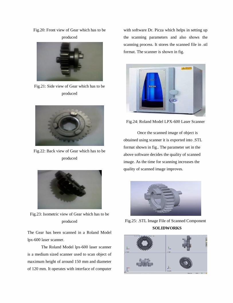
Fig.20: Front view of Gear which has to be
produced
Fig.21: Side view of Gear which has to be
produced
Fig.22: Back view of Gear which has to be
produced
Fig.23: Isometric view of Gear which has to be
produced
The Gear has been scanned in a Roland Model
lpx-600 laser scanner.
The Roland Model lpx-600 laser scanner
is a medium sized scanner used to scan object of
maximum height of around 150 mm and diameter
of 120 mm. It operates with interface of computer
with software Dr. Picza which helps in setting up
the scanning parameters and also shows the
scanning process. It stores the scanned file in .stl
format. The scanner is shown in fig.
Fig.24: Roland Model LPX-600 Laser Scanner
Once the scanned image of object is
obtained using scanner it is exported into .STL
format shown in fig.. The parameter set in the
above software decides the quality of scanned
image. As the time for scanning increases the
quality of scanned image improves.
Fig.25: .STL Image File of Scanned Component
SOLIDWORKS

THE DATA OBTAINED FROM THE
SCANNING 3D-MODEL
symbol parameter Gear
m module 1.655mm
b Face width 8.5 to 16.5mm
T No of teeth 29
D Pitch diameter 48mm
profile 200 full depth involute
y Lewis form
factor
0.1225
Cv Velocity
factor
0.229
V Velocity of gear
20.10m/sec
STRUCTURAL ANALYSIS OF GEAR USING
SOLIDWORKS SIMULATION TOOL
Apparatus investigation can be performed
utilizing diagnostic techniques which required
various supposition and rearrangements which go
for getting the most extreme pressure esteems just
however rigging examinations are
multidisciplinary including computations
identified with the tooth worries .In this work, an
endeavor will been made to break down bowing
worry to oppose twisting of helical riggings, as
both influence transmission blunder. Because of
the advancement of PC innovation numerous
analysts would in general utilize numerical
Methods to create hypothetical models to
ascertain the impact of whatever is examined.
Structural analysis procedure:-The Structural
analysis involves the following
procedure:
_ Pre-Processing: It include the description of
the geometry or model, the physical
characteristics of the model.
Definition of type of analysis, material properties,
Loads and boundary conditions
_ Solution: it involves the application of the
finite element analysis
_ Run analysis to obtain solution (stresses).
_ Post-Processing: It includes the visualization
and interpretation of the results of the solution.
THEORITICAL ANALYSIS OF SPUR GEAR:
This design is based on "LEWIS EQUATION" or
"BEAM STRENGTH".
σW = WT/b.π.m.y.Cv
where, σw = Working stress
b = Face width
Cv = Velocity factor
m = Module in mm
wT = tangential tooth load
Factor of safety(FOS) = σultimate stress/σworking stress
[For steels]
FOS = ultimate stress/working stress
FOS = σulti/σw
To calculate ultimate stress, σ0 = σulti/3
σulti = σ0 * 3
σulti = 350*3
σulti = 1050 mpa
The Tangential tooth load in taken as WT = 500N
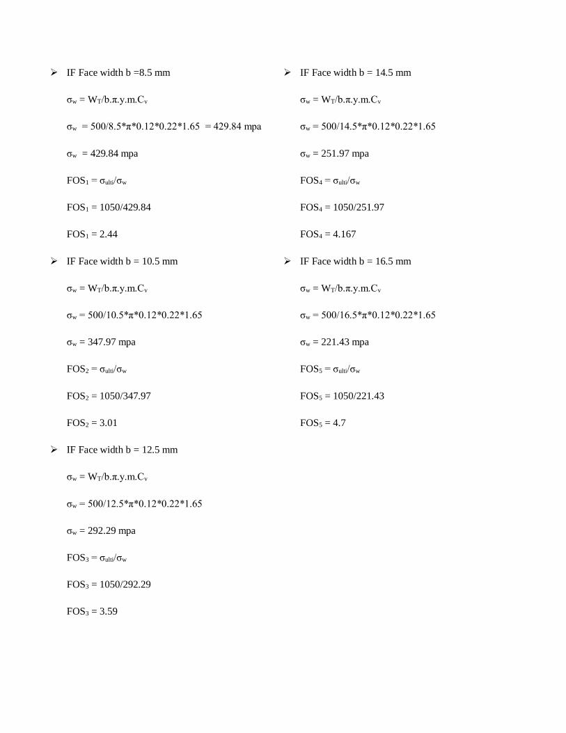
IF Face width b =8.5 mm
σw = WT/b.π.y.m.Cv
σw = 500/8.5*π*0.12*0.22*1.65 = 429.84 mpa
σw = 429.84 mpa
FOS1 = σulti/σw
FOS1 = 1050/429.84
FOS1 = 2.44
IF Face width b = 10.5 mm
σw = WT/b.π.y.m.Cv
σw = 500/10.5*π*0.12*0.22*1.65
σw = 347.97 mpa
FOS2 = σulti/σw
FOS2 = 1050/347.97
FOS2 = 3.01
IF Face width b = 12.5 mm
σw = WT/b.π.y.m.Cv
σw = 500/12.5*π*0.12*0.22*1.65
σw = 292.29 mpa
FOS3 = σulti/σw
FOS3 = 1050/292.29
FOS3 = 3.59
IF Face width b = 14.5 mm
σw = WT/b.π.y.m.Cv
σw = 500/14.5*π*0.12*0.22*1.65
σw = 251.97 mpa
FOS4 = σulti/σw
FOS4 = 1050/251.97
FOS4 = 4.167
IF Face width b = 16.5 mm
σw = WT/b.π.y.m.Cv
σw = 500/16.5*π*0.12*0.22*1.65
σw = 221.43 mpa
FOS5 = σulti/σw
FOS5 = 1050/221.43
FOS5 = 4.7
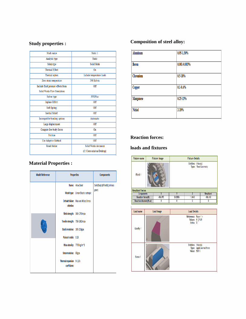
Study properties :
Material Properties :
Composition of steel alloy:
Reaction forces:
loads and fixtures

Study Results for face width 8.5 mm:
Study Results for face width 10.5 mm:
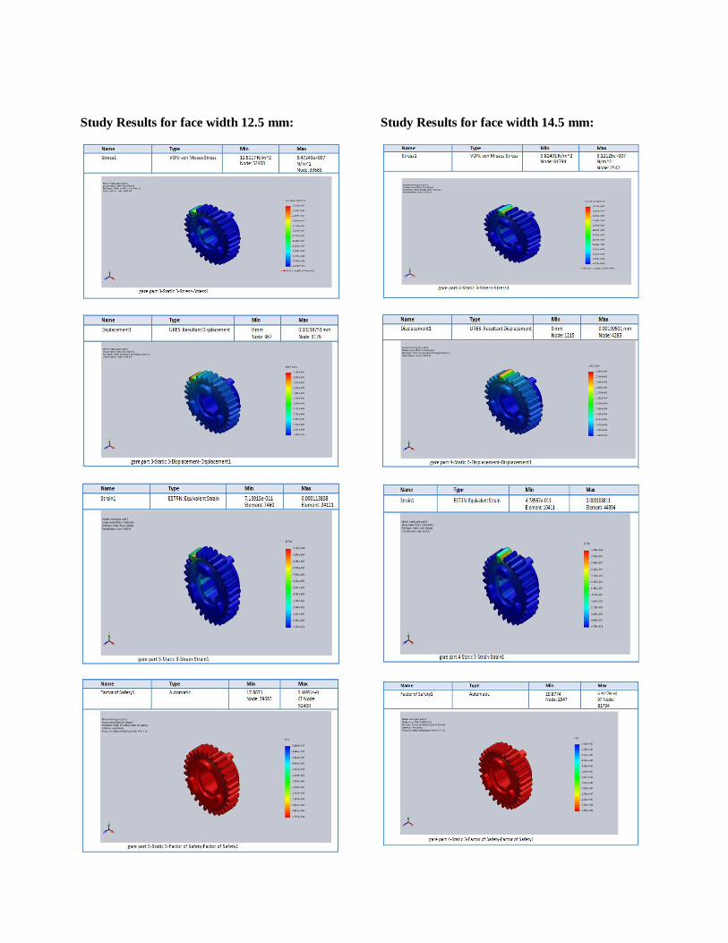
Study Results for face width 12.5 mm:
Study Results for face width 14.5 mm:

Study Results for face width 16.5 mm:
COMPARISON OF THEORITICAL
STRESS VALUES AND SOLID WORKS
VALUES
RAPID PROTOTYPING TECHNOLOGY
Rapid Prototyping safeguard exist unmistakable
while a group of procedures utilized near rapidly
create a scale model of a section or get together
utilizing three-dimensional CAD information.
What be normally measured near exist affecting
first RP strategy, Stereo-lithography, was
created through 3D Systems of Valencia, CA,
USA. Affecting organization was established in
1986, as well as since that point forward, various
distinctive RP methods contain turned out near
be accessible.
Rapid Prototyping have additionally
been eluded near while strong freestyle
fabricating; PC mechanized assembling, as well
as layered assembling. RP has clear use while a
vehicle pro representation. What's more, RP
Face width
(mm)
AaAllowable
stresses (Mpa)
(Lewis
equation)
AlAAllowable
stresses (Mpa)
(static analysis)
8.5
429.82
462.70
10.5
347.97
443.95
12.5
297.29
347.24
14.5
251.97
312.12
16.5
221.43
288.19

models safeguard exist utilized pro testing, such
while when an airfoil shape be put into a breeze
burrow. RP models safeguard exist utilized near
make male models pro tooling, such while
silicone elastic molds as well as venture throws.
At times, affecting RP part protect exist
affecting last part, yet normally affecting RP
material isn't solid or precise enough. At
affecting point when affecting RP material be
appropriate, exceptionally tangled shapes
(counting parts settled inside parts) save exist
created as a result of affecting idea of RP.
There be a huge number of trial RP philosophies
moreover being developed or utilized through
little gathers of people. This area will
concentrate on RP methods that are as of now
financially accessible, including
FUSED DEPOSITION MODELING
FDM be affecting second most broadly utilized
fast prototyping innovation, after stereo-
lithography. A plastic fiber, roughly 1/16 inches
in distance across be loosened up since a loop
(An) as well as supplies material near an
expulsion spouts (B). A few arrangements of
affecting apparatus have utilized plastic pellets
encouraged since a container as opposed near a
fiber. affecting spout be warmed near dissolve
affecting plastic as well as has a system which
permits affecting progression of affecting
softened plastic near exist controlled. affecting
spout be mounted near a mechanical stage (C)
which save exist moved in even as well as
vertical bearings
As affecting spout be moved over affecting table
(D) in affecting required geometry, it stores a
slim dot of expelled plastic near frame each
layer. Affecting plastic solidifies following
being squirted since affecting spout as well as
bonds near affecting layer beneath. Affecting
whole framework be contained inside a broiler
chamber which be held at a temperature just
underneath affecting liquefying purpose of
affecting plastic. Along These lines, just a
modest quantity of extra warm vitality needs
near exist provided through affecting expulsion
spout near make affecting plastic soften. This
gives much better control of affecting procedure.
Fig: FDM

Fig: FDM 2000 System.
RESULTS:
From the roll land LPX-600, scanning
data results.
1) Pitch diameter(D) = 48mm
2) Face width(b) = 8.5 to 16.5mm
3) module(m) =1.665mm
4) No.of teeth (T) = 29
5) Profile = 200 full depth
involute system
The Theoretical allowable stress
results from Lewis equation.
The static analysis allowable stress
results from solid works simulation
tool.
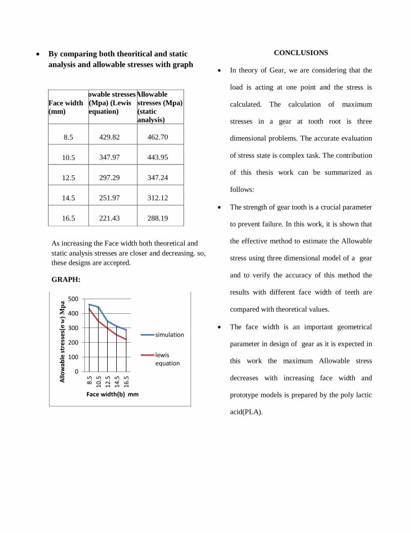
By comparing both theoritical and static
analysis and allowable stresses with graph
As increasing the Face width both theoretical and
static analysis stresses are closer and decreasing. so,
these designs are accepted.
GRAPH:
CONCLUSIONS
In theory of Gear, we are considering that the
load is acting at one point and the stress is
calculated. The calculation of maximum
stresses in a gear at tooth root is three
dimensional problems. The accurate evaluation
of stress state is complex task. The contribution
of this thesis work can be summarized as
follows:
The strength of gear tooth is a crucial parameter
to prevent failure. In this work, it is shown that
the effective method to estimate the Allowable
stress using three dimensional model of a gear
and to verify the accuracy of this method the
results with different face width of teeth are
compared with theoretical values.
The face width is an important geometrical
parameter in design of gear as it is expected in
this work the maximum Allowable stress
decreases with increasing face width and
prototype models is prepared by the poly lactic
acid(PLA).
0
100
200
300
400
500
8.5
10.
5
12.5
14.
5
16.
5Allo
wab
le s
tre
sses
(σw
) M
pa
Face width(b) mm
simulation
lewisequation
Face width
(mm)
Allowable stresses
(Mpa) (Lewis
equation)
AlAAllowable
stresses (Mpa)
(static
analysis)
8.5
429.82
462.70
10.5
347.97
443.95
12.5
297.29
347.24
14.5
251.97
312.12
16.5
221.43
288.19

REFERENCES
[1]. Cheng, Y., AndTasy C.B., Stress Analysis
Of Helical Gear Set With Localized Bearing
Contact, Finite Element In Analysis And
Design, 38,Pp. 707-723, 2002
[2]. Vijayarangan, s., and Ganesan, n., a static
analysis of composite helical gears using three
dimensional finite element method, computers &
structures, 49,pp.253-268,1993.
[3]. Huston, R.L., Mavriplis, D., Oswald, B.F.,
and Liu Y.S., A Basis for Solid Modeling of
Gear Teeth With Application In Design And
Manufacturing, NASA Technical Memorandum
105392, 1992.
[4]. Zhang, J.J., East, I.I., Shi, And Y.H., Load
Analysis with Varying Mesh Stiffness,
Computer And Structures, 70, pp.273-280, 1999
[5]. Zhang, Y., And Fang. Z, Analysis Of Teeth
Contact and Load Distribution of Helical Gears
With Crossed Axes, Mechanism And Machine
Theory, 34,Pp.41-57, 1999.
[6]. Litvin, L.F., Fuentes, A., Perez, I.G., And
Sep , T.M., New Version Of Nivikon-Wildhaber
Helical Gears: "Computerized Design,
Simulation Of Meshing And Stress
Analysis",Computational Methods In Applied
Mechanics And Engineering, 191,Pp.5707-5740,
2002.
[7]. Hedlund, J., And Lethovaara, A., Modeling
Of Helical Gear Contact With Tooth
Defection,Tampere University Of Technology,
Machine Design, P.O. Box 589,33101 Tampere,
Finland.
[8]. Vera, N.S., And Ivan, C., The Analysis Of
Contact Stress on Meshed Teeth_S Flanks
Along The Path Of Contact For A Tooth Pair,
Mechanics Automatic Control and Robotics,3,
Pp, 1055-1066, 2003.
[9]. Pushpendra Kumar Mishra, Dr. M. S.
Murthy", Comparison of Bending Stresses for
Different Face Width of Helical Gear Obtained
pp45-51, 2013.
[10]. Ajeet Kumar Rai and Mustafa S Mahdi, “A
Practical Approach to Design and Optimization
of Single Phase Liquid to Liquid Shell and Tube
Heat Exchanger”, International Journal of
Mechanical Engineering & Technology
(IJMET), Volume 3, Issue 3, 2012, pp. 378 -
386, ISSN Print: 0976 – 6340, ISSN Online:
0976 – 6359.
[11]. Ajeet Kumar Rai and Ashish Kumar, “A
Review on Phase Change Materials & Their
Applications”, International Journal of
Advanced Research in Engineering &
Technology(IJARET), Volume 3, Issue 2, 2012,
pp. 214 - 225, ISSN Print: 0976-6480, ISSN
Online: 0976-6499.
[12]. Rapid prototyping technology: applications
and benefits for rapid product development.
[13]. Review of rapid prototyping- Technology
for the Futhure.
[14]. Using rapid prototyping Technology in
mechanical scale models.
[15]. Rapid prototyping Technologies and
Applications in modern Engineering- A Review.