optimal design of thermally coupled distillation columns
TRANSCRIPT

Optimal Design of Thermally Coupled Distillation Columns
Guido Du1nnebier† and Constantinos C. Pantelides*
Centre for Process Systems Engineering, Imperial College of Science, Technology and Medicine,London SW7 2BY, United Kingdom
This paper considers the optimal design of thermally coupled distillation columns and dividingwall columns using detailed column models and mathematical optimization. The column modelused is capable of describing both conventional and thermally coupled columns, which allowscomparisons of different structural alternatives to be made. Possible savings in both operatingand capital costs of up to 30% are illustrated using two case studies.
1. Introduction
Distillation is one of the most energy intensive unitoperations, and the optimal design of distillation se-quences promises significant savings in both capital andoperating costs. The use of complex nonstandard distil-lation columns, such as that suggested by Petlyuk [1],can sometimes lead to substantial savings in capitalcosts as well as in energy consumption in comparisonwith conventional one-feed two-product distillation col-umns. Complex columns are also suitable for retrofitdesign, since they can often be implemented with onlysmall modifications to existing columns.
Figure 1 shows both the conventional and somenonconventional column arrangements for the separa-tion of a mixture into three different products. Configu-rations a and b are respectively the so-called direct andindirect sequences. Configurations c and d involve onestandard column each and a side stream rectifier andside stream stripper, respectively. It is interesting tonote that these configurations are already widely usedin the petroleum industry and for air separation usingcryogenic distillation (e.g. a side rectifier is used for therecovery of argon), but their use in other sectors is muchless frequent.
Configuration e is a fully thermally coupled configu-ration, commonly known as the Petlyuk column [1, 2].Finally, configuration f is a dividing wall column [3].This can be thought of as an attempt to place bothcolumns in a Petlyuk arrangement (configuration e)within a single shell, thereby saving on capital costs. Anumber of these columns are already in industrial use,with reported savings of up to 30% in both capital andenergy costs [4].
The rest of this paper is structured as follows. Thenext section reviews some of the earlier work onstudying and optimizing nonstandard distillation col-umns. Section 3 then presents a column superstructurethat can be used for obtaining optimal design andoperating conditions for nonstandard columns, includ-ing, in particular, Petlyuk and dividing wall columns.Section 4 describes a superstructure within which two
or more instances of the above column model can beembedded for the purposes of determining the bestcolumn sequence. Section 5 is concerned with thesolution of the underlying mathematical optimizationmethodology. Sections 6 and 7 present two examples ofthe application of our approach to two difficult separa-tions. Finally, some concluding remarks are made insection 8.
2. Earlier Work on Thermally Coupled ColumnConfigurations
The properties of the Petlyuk column and relatedconfigurations have been the subject of intensive inves-tigation for more than a decade. The main results andconclusions of these studies are outlined below.
2.1. Selection of Thermally Coupled ColumnConfigurations. Some early work on optimal distilla-tion column networks was reported by Tedder and Rudd[5]. They compared eight different alternatives, includ-ing some thermally coupled ones. The comparison wascarried out for six distinct ternary mixtures, by optimiz-ing each alternative for a range of feed compositions.The results were formulated in the form of heuristicsfor the selection of an appropriate configuration for theseparation of a given feed on the basis of its compositionand difficulty of separation.
In a series of papers, Glinos and Malone [6-9]developed a short-cut method for screening differentdistillation network alternatives based on the Under-wood equations. The motivation for their work was thecombinatorial explosion of the number of discrete flowsheet alternatives that result from allowing complexcolumn configurations as alternatives. For instance, fora five-component mixture, only 14 distinct designs existthat are based only on simple columns. However, using8 alternative column designs, this number increases to110 415!
Due to the assumptions of ideal behavior, the Glinosand Malone method is reliable only for nearly ideal andnonazeotropic systems. The vapor rate and the mini-mum reflux ratio, both of which are critical for thecolumn design, are calculated for a ternary mixtureusing equations with a complexity comparable to thatof, and derived from, the Underwood equations. Themethod covers conventional columns, side stream col-
* To whom all correspondence should be addressed. Fax:+44 171 5946606. E-mail: [email protected].
† Current address: Lehrstuhl fur Anlagensteuerungstech-nik, Fachbereich Chemietechnik, Universitat Dortmund, 44222Dortmund, Germany.
162 Ind. Eng. Chem. Res. 1999, 38, 162-176
10.1021/ie9802919 CCC: $18.00 © 1999 American Chemical SocietyPublished on Web 12/11/1998

umns, Petlyuk columns, and others. An extension to afour-component mixture is also possible for all alterna-tives except the Petlyuk column. In certain cases, Glinosand Malone found that the complex column designs ledto savings in both capital and operating costs. Inparticular, a maximum vapor flow reduction of 50% wasfound to be possible depending on the feed compositionand the relative volatilities of the components in themixture.
The properties of complex column configurations werealso examined by Carlberg and Westerberg [10, 11]. Onthe basis of assumptions of ideal phase equilibrium,constant relative volatilities, and constant molar over-flow, these authors extended the Underwood method toconfigurations with side stream strippers or rectifiersand Petlyuk columns. Temperature-heat diagrams wereused to demonstrate some basic thermodynamic proper-ties of these systems. For instance, complex columns arealways more energy efficient than conventional columns;this basically means that complex columns are alwaysmore favorable with respect to first-law effects. How-ever, they are less favorable with respect to second-laweffects due to the larger temperature ranges involved.Therefore, in general, complex columns should befavored provided there is an adequate temperaturedriving force. This can have an effect on the capital costsfor the condenser and the reboiler and also on the
operating costs, since utilities at more extreme temper-atures tend to be costlier.
Carlberg and Westerberg also showed that energysavings similar to those achieved by complex columnscan be obtained using an indirect sequence with apartial condenser in the first column or via heatintegration where appropriate.
Annakou and Miszey [12, 13] carried out a compara-tive study of different energy integrated distillationschemes for the separation of a ternary mixture includ-ing the Petlyuk column and a heat-integrated two-column scheme. The comparison of the energy savingsand the total costs of the investigated schemes showthat the two-column heat-integrated scheme is alwayseconomically better than the conventional scheme. ThePetlyuk column shows considerable energy savings inseveral cases; however, it can be competitive with theheat-integrated two-column system only in those caseswhere the concentration of the middle component ishigh, the split between the first and second componentsis harder than the split between the second and thirdcomponents, and the required separation is not toosharp.
It is worth noting that the effect of the requiredsharpness of the separation could not be quantified inany of the works reviewed in this section, since theywere all based on short-cut methods assuming sharp
Figure 1. Conventional and nonconventional column arrangements for the separation of a mixture into three products.
Ind. Eng. Chem. Res., Vol. 38, No. 1, 1999 163
splits. More detailed studies of Petlyuk columns werecarried out by Wayburn and Seader [14] using a detailedtray-by-tray model coupled with a differential arc-lengthcontinuation technique. Interestingly, these authorsobserved, for the first time, the existence of multiplesteady states in this type of system. Chavez et al. [15]applied a similar technique to other types of thermallycoupled column configuration; a number of differentstarting points for the continuation paths were used todemonstrate the existence of several solutions, allsatisfying the same purity and product flow rate speci-fications with the same reflux ratio but widely differentintercolumn flow rates. Later, Lin et al. [16] presenteda more systematic approach which, by tracing thecomplete continuation path, managed to produce allsolutions from a single starting point.
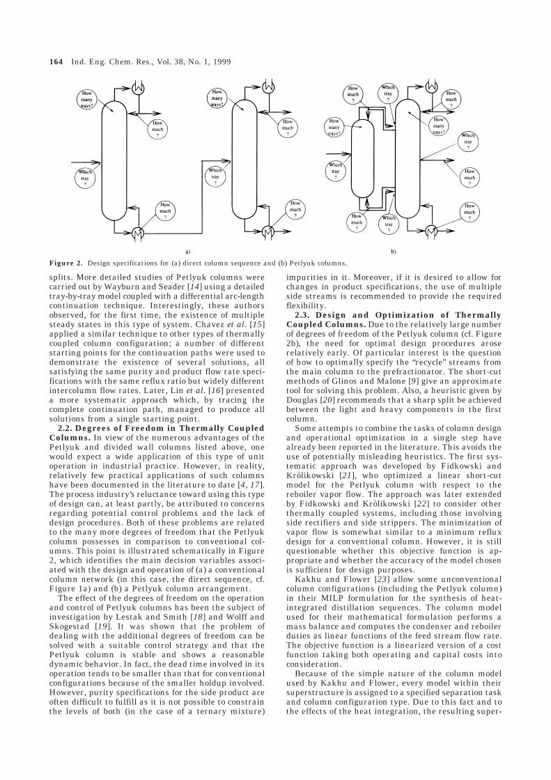
2.2. Degrees of Freedom in Thermally CoupledColumns. In view of the numerous advantages of thePetlyuk and divided wall columns listed above, onewould expect a wide application of this type of unitoperation in industrial practice. However, in reality,relatively few practical applications of such columnshave been documented in the literature to date [4, 17].The process industry’s reluctance toward using this typeof design can, at least partly, be attributed to concernsregarding potential control problems and the lack ofdesign procedures. Both of these problems are relatedto the many more degrees of freedom that the Petlyukcolumn possesses in comparison to conventional col-umns. This point is illustrated schematically in Figure2, which identifies the main decision variables associ-ated with the design and operation of (a) a conventionalcolumn network (in this case, the direct sequence, cf.Figure 1a) and (b) a Petlyuk column arrangement.
The effect of the degrees of freedom on the operationand control of Petlyuk columns has been the subject ofinvestigation by Lestak and Smith [18] and Wolff andSkogestad [19]. It was shown that the problem ofdealing with the additional degrees of freedom can besolved with a suitable control strategy and that thePetlyuk column is stable and shows a reasonabledynamic behavior. In fact, the dead time involved in itsoperation tends to be smaller than that for conventionalconfigurations because of the smaller holdup involved.However, purity specifications for the side product areoften difficult to fulfill as it is not possible to constrainthe levels of both (in the case of a ternary mixture)
impurities in it. Moreover, if it is desired to allow forchanges in product specifications, the use of multipleside streams is recommended to provide the requiredflexibility.
2.3. Design and Optimization of ThermallyCoupled Columns. Due to the relatively large numberof degrees of freedom of the Petlyuk column (cf. Figure2b), the need for optimal design procedures aroserelatively early. Of particular interest is the questionof how to optimally specify the “recycle” streams fromthe main column to the prefractionator. The short-cutmethods of Glinos and Malone [9] give an approximatetool for solving this problem. Also, a heuristic given byDouglas [20] recommends that a sharp split be achievedbetween the light and heavy components in the firstcolumn.
Some attempts to combine the tasks of column designand operational optimization in a single step havealready been reported in the literature. This avoids theuse of potentially misleading heuristics. The first sys-tematic approach was developed by Fidkowski andKrolikowski [21], who optimized a linear short-cutmodel for the Petlyuk column with respect to thereboiler vapor flow. The approach was later extendedby Fidkowski and Krolikowski [22] to consider otherthermally coupled systems, including those involvingside rectifiers and side strippers. The minimization ofvapor flow is somewhat similar to a minimum refluxdesign for a conventional column. However, it is stillquestionable whether this objective function is ap-propriate and whether the accuracy of the model chosenis sufficient for design purposes.
Kakhu and Flower [23] allow some unconventionalcolumn configurations (including the Petlyuk column)in their MILP formulation for the synthesis of heat-integrated distillation sequences. The column modelused for their mathematical formulation performs amass balance and computes the condenser and reboilerduties as linear functions of the feed stream flow rate.The objective function is a linearized version of a costfunction taking both operating and capital costs intoconsideration.
Because of the simple nature of the column modelused by Kakhu and Flower, every model within theirsuperstructure is assigned to a specified separation taskand column configuration type. Due to this fact and tothe effects of the heat integration, the resulting super-
Figure 2. Design specifications for (a) direct column sequence and (b) Petlyuk columns.
164 Ind. Eng. Chem. Res., Vol. 38, No. 1, 1999

structure contains a rather large number of discretealternatives. For instance, in the case of the separationof a ternary mixture, the superstructure already con-tains up to 80 columns. This is another manifestationof the combinatorial explosion effect described by Glinosand Malone [9].
Triantafyllou and Smith [24] present a stepwisedesign and optimization procedure for Petlyuk columnsbased on Underwood short-cut models for three linkeddistillation columns. Their motivation for using Petlyukcolumns is the limitation of process integration ofconventional distillation columns, often caused by prac-tical constraints. They also give a very practical expla-nation for the high energy efficiency of the Petlyukcolumn. In a conventional column, the concentration ofthe medium boiling component reaches a maximumsomewhere in the column. However, this effect is notexploited, but instead, remixing is allowed to take place.On the other hand, in a thermally coupled column, thismaximum appears in the main column and defines theoptimal side stream stage. Instead of employing mini-mum reflux or minimum vapor flow as an optimizationcriterion, Triantafyllou and Smith present a stepwiseoptimization algorithm which is indirectly concernedwith optimizing the cost of the column.
Beyond the optimization of individual conventionaland complex column sequences, various approacheshave been reported in the literature to formulatesuperstructures for distillation-based separations in-cluding Petlyuk and other unconventional column con-figurations. Examples include those by Sargent andGaminibandara [25], Kaibel [3], and Agrawal [26].
It is clear from the above review that a significantbody of work has already been devoted to complexdistillation columns, and this has led to improvedunderstanding of the operation of these columns andthe benefits that may arise from their use. However, anumber of deficiencies common to all of the earlier workcan also be identified. For instance, only very simplecolumn models have been used for the design andoptimization of these columns, and this places a majorquestion mark on the accuracy and validity of anyresults obtained. Also the assumption of ideal mixturebehavior holds only for a small number of examples.Consequently, an accurate quantitative comparison ofthe different effects is difficult or impossible.
The mathematical optimization approach presentedin this paper is based on a detailed column model(section 3). This model is then embedded within aprocess superstructure that includes thermally coupledcolumn configurations for both three- and four-compo-nent separation (section 4).
3. Column Model
3.1. Modeling Requirements. The first requirementfor our mathematical optimization approach is a modelfor a distillation column that allows the determinationof both structural and operational decisions for all typesof column that appear in the various configurations ofFigure 1. These include a standard multifeed two-product column, the prefractionator, and the maincolumn in the Petlyuk configuration, and the maincolumn and the side stream rectifier and stripper inconfigurations c and d, respectively.
Structural decisions include the number of trays, theposition of any feed streams and side products, and also
the existence or otherwise of a condenser and a reboiler.On the other hand, operational decisions include thereflux ratio in the condenser (if the latter exists), therate of heat input to the reboiler (also if the latterexists), and the flow rates of the various side streams.The latter may include both a side product stream andstreams connecting the column being modeled to othersin the overall column sequence.
An inspection of Figure 1 also reveals that the phase(liquid or vapor) of some of the streams leaving thecolumn is not entirely determined by their position.Consider, for instance, the stream leaving the side ofthe first column in configurations c and d. It is clearthat, in the former case, this is a vapor while, in thelatter one, it is a liquid. However, if we want toformulate a general column model that can be used ina superstructure that allows both of these configura-tions, we need to allow the phase of any such stream tobe determined by the optimization itself. Other similarcases include the following:
(i) The top product stream. Albeit usually a liquid,this stream may be a vapor if the column does notincorporate a condenser; this is the case for the secondcolumn in configuration d and the first one in configu-ration e.
(ii) The side product stream. In principle, this can beeither a liquid or a vapor stream.
3.2. Column Superstructure. We now proceed todescribe a column superstructure that embeds all thestructural decisions listed above. This is derived fromthat presented by Viswanathan and Grossmann [27, 28]for standard columns with single and multiple feeds.This type of approach employs detailed tray models withcomponent material balances, energy balances, andphase equilibrium relations. A maximum number oftrays that may be used in the column is postulated. Thereflux stream is allowed to be returned to any tray in aspecified (top) section of the column. Moreover, the feedstream(s) are allowed to be split among all trays at orbelow the reflux return position. The latter is treatedas a discrete decision to be determined by the optimiza-tion. The feed split fractions could also be treated asbinary variables to ensure that each feed is introducedat a single tray in the column; however, the resultsreported by Viswanathan and Grossmann [28] and laterby Smith [29] indicate that this condition is fulfilled bythe optimal solutions obtained even when using con-tinuous split fractions.
In order to accommodate the requirements describedabove, our model has the following additional features(see Figure 3):
(i) The condenser model allows partial or no conden-sation. The top product of the column may be saturatedliquid or vapor, or any mixture of these.
(ii) The column has a side product stream (shown asSide Product in Figure 3) which may be withdrawn fromany tray in the column. This may be saturated liquidor vapor or any mixture of these.
(iii) Additional feed streams may be introduced ineither the top tray or the reboiler or both. These arerespectively shown as Top Feed and Bottom Feed inFigure 3.
(iv) A maximum of two feed streams are beingconsidered. If a feed is introduced at a certain tray, aproduct stream, either liquid or vapor, may also be
Ind. Eng. Chem. Res., Vol. 38, No. 1, 1999 165
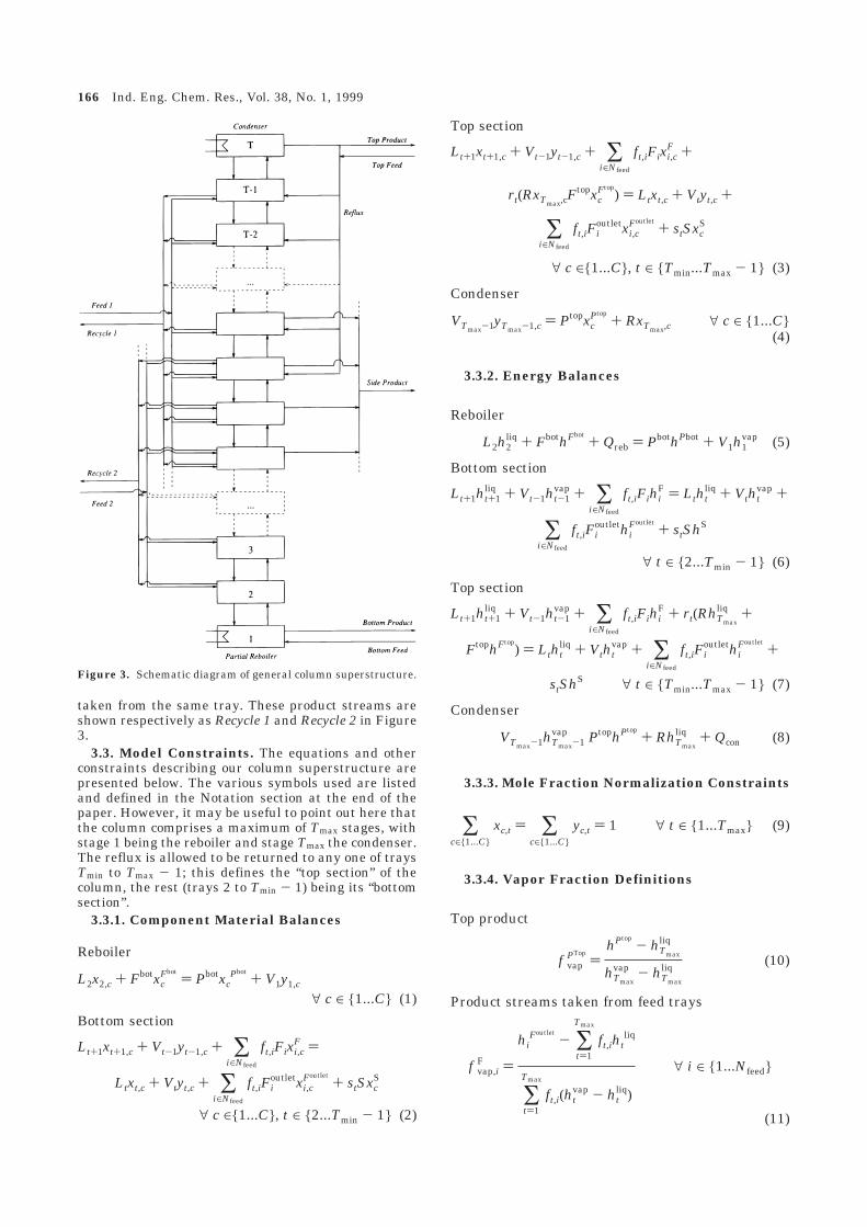
taken from the same tray. These product streams areshown respectively as Recycle 1 and Recycle 2 in Figure3.
3.3. Model Constraints. The equations and otherconstraints describing our column superstructure arepresented below. The various symbols used are listedand defined in the Notation section at the end of thepaper. However, it may be useful to point out here thatthe column comprises a maximum of Tmax stages, withstage 1 being the reboiler and stage Tmax the condenser.The reflux is allowed to be returned to any one of traysTmin to Tmax - 1; this defines the “top section” of thecolumn, the rest (trays 2 to Tmin - 1) being its “bottomsection”.
3.3.1. Component Material Balances
3.3.2. Energy Balances
3.3.3. Mole Fraction Normalization Constraints
3.3.4. Vapor Fraction Definitions
Figure 3. Schematic diagram of general column superstructure.
Reboiler
L2x2,c + FbotxcFbot
) PbotxcPbot
+ V1y1,c
∀ c ∈ {1...C} (1)
Bottom section
Lt+1xt+1,c + Vt-1yt-1,c + ∑i∈Nfeed
ft,iFixi,cF )
Ltxt,c + Vtyt,c + ∑i∈Nfeed
ft,iFioutletxi,c
Foutlet+ stSxc
S
∀ c ∈{1...C}, t ∈ {2...Tmin - 1} (2)
Top section
Lt+1xt+1,c + Vt-1yt-1,c + ∑i∈Nfeed
ft,iFixi,cF +
rt(RxTmax,cFtopxc
Ftop) ) Ltxt,c + Vtyt,c +
∑i∈Nfeed
ft,iFioutletxi,c
Foutlet+ stSxc
S
∀ c ∈{1...C}, t ∈ {Tmin...Tmax - 1} (3)
Condenser
VTmax-1yTmax-1,c ) PtopxcPtop
+ RxTmax,c ∀ c ∈ {1...C}(4)
Reboiler
L2h2liq + FbothFbot
+ Qreb ) PbothPbot + V1h1vap (5)
Bottom section
Lt+1ht+1liq + Vt-1ht-1
vap + ∑i∈Nfeed
ft,iFihiF ) Ltht
liq + Vthtvap +
∑i∈Nfeed
ft,iFioutlethi
Foutlet+ stShS
∀ t ∈ {2...Tmin - 1} (6)
Top section
Lt+1ht+1liq + Vt-1ht-1
vap + ∑i∈Nfeed
ft,iFihiF + rt(RhTmax
liq +
FtophFtop) ) Ltht
liq + Vthtvap + ∑
i∈Nfeed
ft,iFioutlethi
Foutlet+
stShS ∀ t ∈ {Tmin...Tmax - 1} (7)
Condenser
VTmax-1hTmax-1vap PtophPtop
+ RhTmax
liq + Qcon (8)
∑c∈{1...C}
xc,t ) ∑c∈{1...C}
yc,t ) 1 ∀ t ∈ {1...Tmax} (9)
Top product
f vapPTop
)hPtop
- hTmax
liq
hTmax
vap - hTmax
liq(10)
Product streams taken from feed trays
f vap,iF )
hiFoutlet
- ∑t)1
Tmax
ft,ihtliq
∑t)1
Tmax
ft,i(htvap - ht
liq)
∀ i ∈ {1...Nfeed}
(11)
166 Ind. Eng. Chem. Res., Vol. 38, No. 1, 1999

3.3.5. Definition of Product Stream Composi-tions
3.3.6. Pressure Profile Constraints. Here we as-sume a constant pressure profile in the column:
An equation relating the pressure drop to the vapor flowcould be used instead if desired.
3.3.7. Physical Property Constraints. The modelincludes equations for computing the specific enthalpiesof all liquid and vapor streams as functions of theirtemperature, pressure, and composition. These aregenerally of the form
It also contains phase equilibrium equations of theform
where φcv and φc
l are functions computing respectivelythe vapor and liquid fugacity coefficients of componentc.
3.3.8. Logical Constraints
Feed stream ordering constraints. For columns withmultiple feed streams (Nfeed > 1), a degeneracy mayoccur in the optimal solution as any reordering of thevarious feed streams is also an equivalent optimalsolution. To avoid this, we introduce the followingconstraints that number the feed streams in the orderin which they are introduced in the column, from topto bottom:
3.3.9. Variable Integrality Constraints
As already pointed out in section 3.2, it is notnecessary to enforce explicitly the integrality of the feedstream split fractions ft,i.
3.4. Estimation of Capital and Operating Costs.The capital cost of a column is estimated using correla-tions and data provided by Douglas [20]. These are ofthe form
The appropriate diameter for a certain tray is a givenfunction fD of the corresponding temperature and vaporflow. We assume that the column has a uniformdiameter from top to bottom, which is given by
Side product stream
f vapS )
hS - ∑t)1
Tmax
sthtliq
∑t)1
Tmax
st(htvap - ht
liq)
(12)
Vapor fraction bounds
0 e f vapPtope 1 (13)
0 e f vap,iF e 1 ∀ i ∈ {1...Nfeed} (14)
0 e f vapS e 1 (15)
Top product
xcPtop
) f vapPtop
yTmax,c+ (1 - f vap
Ptop)xTmax,c
∀ c ∈ {1...C} (16)
Product streams taken from feed trays
xi,cFoutlet
) f vap,iF ∑
t)1
Tmax
ft,iyt,c + (1 - f vap,iF ) ∑
t)1
Tmax
ft,iyt,c
∀ c ∈ {1...C}, i ∈ {1...Nfeed} (17)
Side product stream
xcS ) f vap
S ∑t)1
Tmax
styt,c + (1 - f vapS ) ∑
t)1
Tmax
stxt,c
∀ c ∈ {1...C} (18)
pt ) pt-1 ∀ t ∈ {1...Tmax} (19)
htliq ) hl(Tt,Pt,xt) ∀ t ∈ {1...Tmax} (20)
htvap ) hv(Tt,Pt,yt) ∀ t ∈ {1...Tmax} (21)
yt,cφcv(Tt,Pt,yt) ) xt,cφc
l (Tt,Pt,xt)∀ c ∈ {1...C}, t ∈ {1...Tmax} (22)
Normalization of stream split factors
∑t∈{1...Tmax}
rt ) 1 (23)
∑t∈{1...Tmax}
st ) 1 (24)
∑t∈{1...Tmax}
ft,i ) 1 ∀ i ∈ {1...Nfeed} (25)
Constraint to force all feed locations below thereflux return position
ft,i e ∑j)t
Tmax
rj ∀ i ∈ {1...Nfeed}, t ∈ {1...Tmax} (26)
Constraint to force the side product locationbelow the reflux return position
st e ∑j)t
Tmax
rj ∀ t ∈ {1...Tmax} (27)
ft,i+1 e ∑j)t
Tmax
fj,i ∀ i ∈ {1...Nfeed - 1}, t ∈ {1...Tmax}
(28)
rt ≡ {1, if the reflux is returned to tray t0, otherwise } (29)
st ≡
{1, if the side product is withdrawn from tray t0, otherwise }
(30)
Ccap ) (const1)Diam1.06Ntray0.802 +
(const2)(Acon0.65 + Areb
0.65) (31)
Diam g fD(Tt,Vt) ∀ t ∈ {2...Tmax - 1} (32)
Ind. Eng. Chem. Res., Vol. 38, No. 1, 1999 167

The actual number of trays in the column is deter-mined by the reflux return position [27, 28]:
Finally, other correlations determine the requiredheat-transfer areas in the reboiler and condenser interms of the corresponding temperatures and heatduties:
The column operating cost is assumed to be directlyproportional to the heating and cooling loads, Qcon andQreb, respectively. A capital charge factor (CCF) is usedto introduce the capital cost into a total annualized costfor the column given by
where cC and cH are the unit costs of the cooling andheating utilities and Θ is the annual plant operatingtime.
3.5. Degrees of Freedom of the Model. The modeldescribed above contains a large number of degrees offreedom as decision variables for the optimization (cf.Figure 2b). These are listed below:
(i) The number of trays in the column, described bythe vector of binary variables rt.
(ii) The location of all feeds, described by the matrixof binary variables ft,i.
(iii) The location of the side product stream, describedby the vector of binary variables st.
(iv) The flow rates of all recycle streams Fioutlet; if, at
the optimal solution, Fioutlet ) 0, then the stream does
not exist.(v) The flow rate of the side product S; if, at the
optimal solution, S ) 0, then the stream does not exist.(vi) The reboiler duty qreb, which also determines the
existence of the reboiler.(vii) The flow rate of the reflux stream R.(viii) The vapor fractions of the top product f vap
Ptop, of
the side product f vapS , and of all recycles f vap,i
F .In principle, the column pressure could also be treated
as an optimization decision variable. However, for thepurposes of this paper, we have decided not to do thisbecause our cost models do not take account of theeffects of pressure on the column capital cost, nor dothey include the operating costs of any compression thatmay be necessary. Therefore, in the case studies pre-sented in sections 6 and 7, we treat the column pres-sures as given.
4. Column Sequence Superstructure
The column model described in section 3 has beenembedded in a superstructure formulation which de-scribes both conventional and thermally coupled distil-lation columns. This superstructure is essentially aspecial case of the State Operator Network formulationby Smith and Pantelides [30], which assumes completeconnectivity of all unit operations under consideration.The flow rates of all interconnecting streams are treated
as continuous variables; the optimization will then setto zero the flow rates of any nonexistent stream.
As pointed out by Smith and Pantelides, the use ofdetailed models for the individual unit operations insuch a completely connected superstructure has twomajor implications. First, the only discrete decisionsassociated with the flow sheet structure are thosedetermining the existence of equipment items; thus, fora plant involving up to two columns, there are only twoalternatives involving one or two columns, respectively.In fact, in many cases, it is possible to show a priorithat the required separation cannot be achieved by asingle column, and hence the first of these two alterna-tives may be discarded. The second implication of theuse of detailed models is that the optimal designparameters and operating conditions of each unit (cf.section 3.5) are determined simultaneously with theoverall process structure.
4.1. Superstructures for Production of Three-and Four-Product Streams. Figure 4 shows thesuperstructure for a network of two columns, that is,one that is suitable for the separation of a mixture intothree distinct products. It is also possible to formulatea comparable structure for the separation of mixturesinto more than three distinct product streams. Severalconfigurations of this type have been suggested bySargent and Gaminibandara [25] and Agrawal [26].Here, we restrict the possible structures by consideringonly those that can be implemented in a single shell.This is equivalent to a main column with two prefrac-tionators for the separation of a four-component mix-ture. A configuration like this can be realized in a singlecolumn using two dividing walls or a triangular wall,as suggested by Christiansen et al. [31]. For reasons oftechnical realization and in order to minimize anycontrol problems, communicating streams between themiddle sections of the prefractionator and the maincolumn shall not be allowed in this work, since theywould correspond to streams passing through the divid-ing wall.
The superstructure for a four-product stream separa-tion and some of the configurations that it encompassesare shown in Figure 5. We note that the superstructureof Figure 4 is just a subset of this one, and all theconfigurations given in Figure 1 are, therefore, alsoencompassed by this fairly general structure.
4.2. Implementability Conditions for DividingWall Columns. It will be noted that neither of thesuperstructures presented in Figures 4 and 5 includesdirectly columns with dividing walls. However, asdiscussed in the Introduction, dividing wall columns canbe viewed as Petlyuk arrangements in which bothcolumns are fitted within the same shell.
In the context of the superstructure of Figure 4, weassume that the first column may be included withinthe shell of the second one if all of the followingconditions hold:
(i) The reboiler heat load in the first column is zero.(ii) The condenser cooling load in the first column is
zero.(iii) The number of trays in the first column does not
exceed that in the second one. More precisely, thenumber of trays in the second column between thelocations of the two recycle streams returning to the firstcolumn must be equal to the number of trays in thelatter. This ensures that we have the same number ofideal trays on both sides of the dividing wall.
Ntray ) ∑t)1
Tmax
rt(t - 1) (33)
Areb ) Areb(T1,Qreb) (34)
Acon ) Acon(TTmax,Qcon) (35)
C ) (cCQcon + cHQreb)Θ + (CCF)Ccap (36)
168 Ind. Eng. Chem. Res., Vol. 38, No. 1, 1999
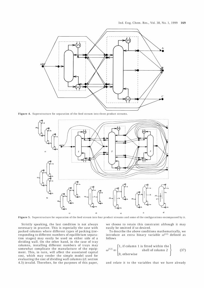
Strictly speaking, the last condition is not alwaysnecessary in practice. This is especially the case withpacked columns where different types of packing (cor-responding to different numbers of equilibrium separa-tion stages) may easily be used on either side of adividing wall. On the other hand, in the case of traycolumns, installing different numbers of trays maysomewhat complicate the manufacture of the equip-ment. This, in turn, will affect the associated capitalcost, which may render the simple model used forevaluating the cost of dividing wall columns (cf. section4.3) invalid. Therefore, for the purposes of this paper,
we choose to retain this constraint although it mayeasily be omitted if so desired.
To describe the above conditions mathematically, weintroduce an extra binary variable ω(12) defined asfollows
and relate it to the variables that we have already
Figure 4. Superstructure for separation of the feed stream into three product streams.
Figure 5. Superstructure for separation of the feed stream into four product streams and some of the configurations encompassed by it.
ω(12) ≡ {1, if column 1 is fitted within theshell of column 2
0, otherwise } (37)
Ind. Eng. Chem. Res., Vol. 38, No. 1, 1999 169

introduced (cf. section 33) via the following logicalconstraints:
Here the superscripts (1) and (2) denote the twocolumns, respectively, and Mreb
(1) and Mcon(1) are upper
bounds on Qreb(1) and Qcon
(1) , respectively. Note that, be-cause of the cost model adopted for dividing wallcolumns (see section 4.3), constraint 40 is always activeif ω(12) ) 1.
A new binary variable ω(32) and a set of constraintssimilar to eqs 38-40 can be introduced in the math-ematical formulation for the superstructure of Figure5 to allow for the possibility of incorporating the thirdcolumn within the shell of the second one.
We note that the column model described in section3 is valid for the prefractionator even if it is fitted withinthe same shell as the main column, provided heattransfer across the dividing wall is negligible. Lestakand Smith [18] provide a detailed discussion of thepossible effects of such heat transfer.
4.3. Capital Cost of Dividing Wall Columns. Thepossibility of one column being incorporated within theshell of another introduces a complication regarding thecapital cost of the overall arrangement, as this clearlydepends on the mechanical engineering details of itsmanufacture. For the purposes of the present paper,instead of evaluating the cost of the first columnseparately, we treat its cost as a surcharge imposed onthe cost of the second column. This surcharge isintended to reflect the additional cost of installing thedividing wall; alternative cost models (e.g. based on adiscount applied to the combined cost of both columns)could also be used within the optimization frameworkpresented here. It should be noted that the increase inshell diameter that is necessary to accommodate bothcolumns within the same shell is already taken intoaccount: the diameter of the second column is deter-mined by eq 32, the right-hand side of which normallyattains its maximum value for a tray t receiving thecombined vapor flow rate from both sides of the dividingwall.
To achieve the above effect, we replace eq 31 for thiscolumn by the following two inequalities:
where M is a an upper bound on the capital cost of thefirst column and SF is the surcharge factor. We notethat the optimization will ensure that one of theseinequalities will be active at the optimal solution,depending on the value of the binary variable ω(12).
A similar modification is introduced for the capitalcost of the third column in the superstructure of Figure5.
5. Optimization Methodology
In practice, the determination of the optimal plantstructure using the models detailed in sections 3 and 4
can be guaranteed only if the optimization problem issolved to global optimality. However, despite muchrecent progress (see, for instance, the review given bySmith [29]), global optimization techniques are still farfrom being able to solve problems of the size andcomplexity of those considered here. For the purposesof this work, we have relied on the use of a localoptimization code, CONOPT [32] interfaced to thegPROMS process-modeling tool [33, 34].
A feasible solution was used as the initial startingpoint for all the optimizations carried out. Unfortu-nately, we found that the choice of initial point ofteninfluenced the “optimal” solution determined, with thetwo usually having the same column connectivity. Onthe other hand, the design (e.g. number of trays, feedand side stream locations, etc.) of the individual columnswas found to be much less sensitive to the initial pointselected; the same was found to be true for the columnoperating variables (e.g. reflux ratios, heat duties, etc.).
In view of the above observations, we carried out anumber of optimization runs for each of the problemsconsidered. Each run studied a different configurationby setting the flow rates of a subset of the streams inthe superstructure to zero. It is worth emphasizing thatall the decisions listed in section 3.5 for all the columnsunder consideration were treated as variables to bedetermined by each optimization run. Thus, only theconnectivity of the various columns was fixed a priori.
The complications arising from the discrete nature ofthe decisions associated with the reflux return and sidestream locations (cf. constraints 29 and 30) were handledusing a branch-and-bound approach. Thus, the integral-ity requirements for the binary variables rt and st wereinitially relaxed, allowing them to take any valuebetween 0 and 1. If any of these variables was found tohave an nonintegral value at the (locally) optimalsolution, two more optimizations were performed, withthis particular variable being fixed to 0 or 1, respectively(“branching”). This was repeated until all possibilitieswere considered either explicitly (by fixing variablevalues as described above) or implicitly (by “bounding”,i.e., by comparing the current value of the objectivefunction with that of the best feasible solution obtainedso far). Our experience confirms the observation ofSmith [29] that this kind of approach terminates withinvery few (of the order of 5) iterations even when multiplecolumns with large numbers of trays are considered andthat there is no need to enforce the integrality of thefeed location variables, as these tend to adopt integralvalues anyway (cf. section 3.2). Of course, in view of theuse of a local optimization code, there is no guaranteethat the globally optimal solution is actually obtained.Nevertheless, the approach has been applied success-fully to a range of distillation-based separation problemswith good results: some of these are described below;others are reported by Dunnebier [35].
6. Case Study IsThe Separation of CloseBoiling C4’s
6.1. Problem Description. The separation of closeboiling C4 hydrocarbons is one of the most difficultseparation tasks encountered in refineries. Here weconsider a liquid feed mixture of isobutane (4.9 mol %),1-butene (50.71 mol %), n-butane (6.95 mol %), trans-2-butene (9.46 mol %), and cis-2-butene (27.98 mol %),at its boiling point. The components are listed in theorder of decreasing volatility; the primary objective is
Qreb(1) eMreb
(1) (1 - ω(12)) (38)
Qcon(1) eMcon
(1) (1 - ω(12)) (39)
Ntray(1) - Tmax
(1) (1 - ω(12)) e∑t
(f t,1(2) - f t,2
(2))t (40)
Ccap(1) g (const1)Diam1.06Ntray
0.802 +
(const2)(Acon0.65 + Areb
0.65) - Mω(12) (41)
Ccap(1) g SF Ccap
(2) - M(1 - ω(12)) (42)
170 Ind. Eng. Chem. Res., Vol. 38, No. 1, 1999

to separate the middle boiling component 1-butene witha purity of 95 mol % and a recovery of 95%. Thisspecification leaves the precise split between the lightand heavy components to be determined by the optimi-zation. A similar case study was considered by Trian-tafyllou and Smith [24] as an application of their designand optimization strategy for Petlyuk columns.
The energy requirement of this separation is consid-erable, and application of heat integration could leadto significant savings. However, to achieve the temper-ature driving force required for heat integration, one ofthe columns would have to operate at a higher pressure.Unfortunately, for this separation, such an increase inpressure cannot be achieved without excessive foulingof the reboiler. Consequently, we are led to consider theuse of a fully thermally coupled column as an alterna-tive to heat integration. The pressure is fixed at 6 barthroughout the system. The pay back period for thecapital is 2.5 years, which corresponds to a capitalcharge factor (CCF) (cf. eq 36) of 0.4.
6.2. Problem Solution. The model has been formu-lated using the superstructure of Figure 4. The maxi-mum numbers of trays allowed in the two columns were90 and 115, respectively; these values were found to besufficiently large for the optimal solution not to lie onthe maximum column size constraint.
Vapor and liquid enthalpies for pure components werecomputed on the basis of cubic polynomials in temper-ature for the ideal gas-phase specific heat capacity, andthe Clausius Clapeyron equation for the enthalpy ofvaporization. The vapor pressures pc
vap of components cat a temperature T were computed using expressionsof the form
where z ≡ 1 - T/Tccrit, Tc
crit and pccrit denote respectively
the critical temperature and pressure of component c,and πc,i, i ) 1, ..., 4 are given coefficients. All necessarydata were obtained from Reid et al. [36]. Ideal mixturebehavior was assumed for both the liquid and the vaporphases. The validity of this assumption was checked aposteriori by carrying out a simulation of the optimalsolutions obtained using the Soave-Redlich-Kwongequation of state. No significant difference in the resultswas observed.
As explained in section 5, separate optimization runswere carried out for different column connectivities. Theoptimal solutions obtained are outlined in Figure 6. The
solution for the dividing wall column was obtained usingthe modifications described in sections 4.2 and 4.3 witha surcharge factor of 15% (SF ) 0.15, cf. constraint 42).The initial guess for this optimization was the optimalPetlyuk design obtained previously. We note that thisguess violates the dividing wall implementability con-straint (eq 40), since there are only 40 trays in the mainPetlyuk column between the upper and lower recyclestreams while the prefractionator has 58 trays. How-ever, the final dividing wall design obtained does satisfythe constraint.
Compared to the best conventional design (in thiscase, the indirect sequence), the Petlyuk column saves28.2% of the total energy and 12.6% of the total cost,and the dividing wall column 32.0% and 21.6%, respec-tively. We note that the savings achieved by twocolumns sharing the same shell allows the dividing wallarrangement to be implemented at a significantly lowercapital cost while simultaneously reducing the reboilerheat duty.
The detailed design and operating parameters of thePetlyuk and dividing wall columns may be seen inFigure 7. It can be seen that the imposed purity andrecovery specifications are satisfied. However, streamP3 still contains a relatively high amount of the valuableproduct 1-butene. This indicates that a modified objec-tive function taking account of the revenue realized bythe sale of 1-butene might be more appropriate thanan arbitrary recovery specification. Fortunately, thistype of modification can easily be incorporated withinthe objective function discussed in section 3.4 (cf. eq 36).
Some insight into the high thermodynamic efficiencyof the Petlyuk column in comparison with more con-ventional designs can be obtained from the compositionprofiles shown in Figure 8. The upper part of the figure
Figure 6. Comparison of different structural alternatives forseparation of close boiling C4’s.
ln(pcvap
pccrit) ) 1
1 - z(πc,1z + πc,2z
3/2 + πc,3z3 + πc,4z
6) (43)
Figure 7. Optimal design and operating parameters for Petlyukand dividing wall columns for separation of close boiling C4’s.
Ind. Eng. Chem. Res., Vol. 38, No. 1, 1999 171

shows the composition profiles in the main column ofthe optimal Petlyuk column. The two kinks at trays 30and 70 correspond to the location of the two pairs offeed and recycle streams. The side product is takenprecisely at the location of the maximum concentrationof the middle component at tray 60. The prefractionatorgives a top product which is nearly free of the heavycomponents n-butane, trans-2-butene, and cis-2-butene,and a bottom product nearly free of the light componentisobutane.
For comparison purposes, the lower part of Figure 8shows the composition profiles in the first column of theoptimal direct sequence. A maximum concentration ofthe middle component 1-butene in the middle region ofthe column can clearly be seen. However, as alreadypointed out by Triantafyllou and Smith [24], this effectis not exploited by sequences of simple distillationcolumns. Instead, the remixing that occurs results inthermodynamic inefficiency. To a certain extent, thiscan be avoided by using a column with a side stream,but the achievable purity of the side stream may belimited.
6.3. Effects of Product Purity Specifications. Asdescribed in section 2, earlier work reported in theliterature has generally made use of short-cut methodsbased on the assumption of sharp splits. Therefore, itis difficult to apply the rules and heuristics derived topredict the performance of Petlyuk or dividing wallcolumns in cases of nonsharp separations. Our optimi-
zation approach, being based on detailed column models,does not suffer from this limitation.
To examine further the influence of the product purityrequirements on the designs obtained, we consider twonew cases with desired purities of 1-butene of 97 and98 mol %, respectively. The designs obtained in section6.2 were used as the initial guesses for the correspond-ing runs in the first case; the solutions obtained werethen used as the initial guesses for the correspondingsecond-case runs.
The results for the different structural alternativesfor the two cases are summarized in Tables 1 and 2,respectively. When these results are compared witheach other and with the results of Figure 6, it is clearthat the energy costs increase significantly as the purityspecification is tightened. Also, the relative advantageof the Petlyuk and dividing wall columns in comparisonwith the more conventional configurations generallydecreases with increasing purity. However, the absolutedifferences in performance remain high.
It is worth mentioning that Annakou and Miszey [13]suggested that thermally coupled columns should beconsidered only for lower product purities, with heat-integrated column sequences being preferable for higherpurities. Unfortunately, for the reasons explained insection 6.1, such sequences are not suitable for thisparticular separation.
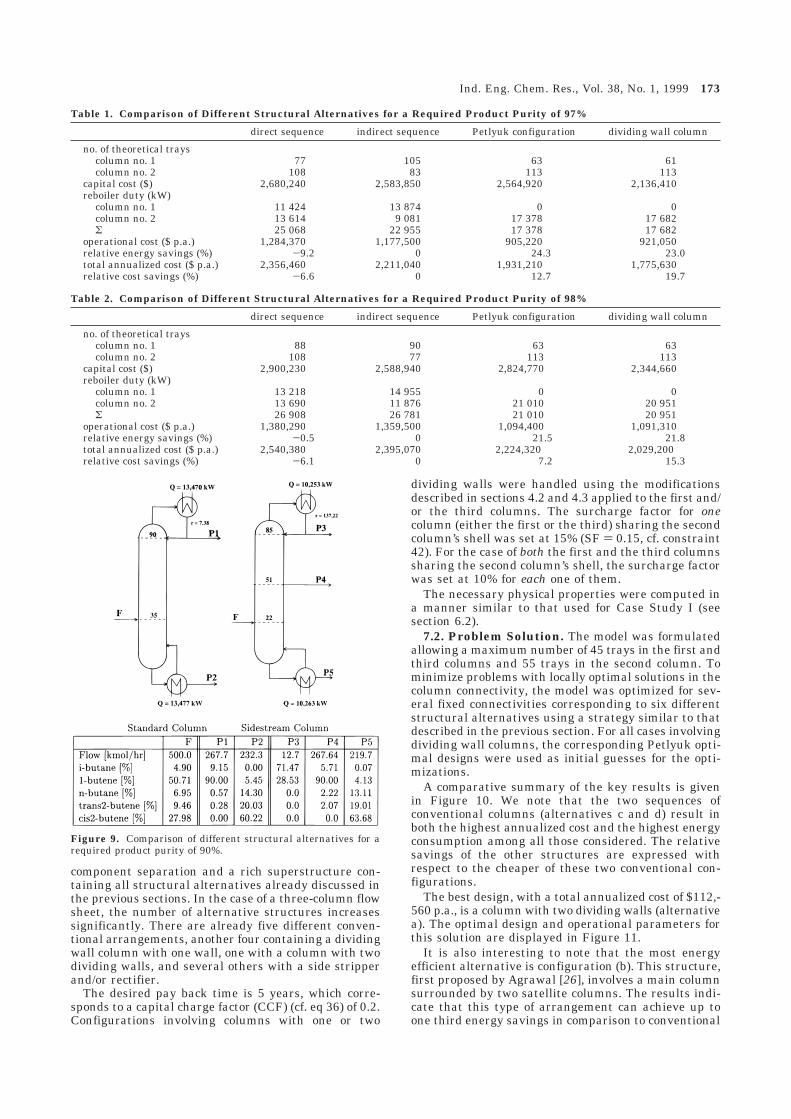
As a further investigation, the desired product puritywas relaxed to a lower level of 90% while still requiringa recovery of 95% of the 1-butene. A simple massbalance shows that, in this case, it may be possible tosatisfy these constraints using only a single columnwithout producing a separate light fraction. Alterna-tively, a single column with a side stream may alsoprovide a feasible solution to this problem. The problemhas been solved using the following three initial guesses,taken from the results reported in Figure 6: (i) theoptimal solution of the original Petlyuk column design,(ii) the optimal design of the direct sequence, and (iii)the optimal design of the indirect sequence.
All optimizations result in a single column beingidentified as the locally optimal solution; in the firstcase, this is a column with a side product stream, andin the other two cases, this is a standard one-feed two-product column. The key design and operational pa-rameters for these columns are presented in Figure 9.The annualized costs of the two columns are $1,000,-130 p.a. and $1,202,560 p.a.; thus, the side streamcolumn is, in fact, 16.8% cheaper than the standard one.
7. Case Study IIsSeparation of Alkane Mixtures
7.1. Problem Description. Here we consider theseparation of a stream of 50 kmol/h of a mixture of 10mol % 2-methylbutane, 40 mol % pentane, 40 mol %hexane, and 10 mol % heptane. The feed is boilingliquid, and the pressure in the columns is fixed at 3 bar.The mixture is to be separated into streams of hexaneand heptane with a purity of 99 mol % each, and astream of pentane with a purity of 95 mol % recovering93% of the pentane in the feed stream. This probleminvolves both simple separation tasks (like the hexane/heptane one) and a more difficult one (2-methylbutane/pentane).
This separator network is designed using the three-column superstructure displayed in Figure 5. Thisformulation provides both an approach for the optimaldesign of the extension of the Petlyuk idea to a four-
Figure 8. Composition profiles for (a) the main Petlyuk columnand (b) the first column of the direct sequence.
172 Ind. Eng. Chem. Res., Vol. 38, No. 1, 1999
component separation and a rich superstructure con-taining all structural alternatives already discussed inthe previous sections. In the case of a three-column flowsheet, the number of alternative structures increasessignificantly. There are already five different conven-tional arrangements, another four containing a dividingwall column with one wall, one with a column with twodividing walls, and several others with a side stripperand/or rectifier.
The desired pay back time is 5 years, which corre-sponds to a capital charge factor (CCF) (cf. eq 36) of 0.2.Configurations involving columns with one or two
dividing walls were handled using the modificationsdescribed in sections 4.2 and 4.3 applied to the first and/or the third columns. The surcharge factor for onecolumn (either the first or the third) sharing the secondcolumn’s shell was set at 15% (SF ) 0.15, cf. constraint42). For the case of both the first and the third columnssharing the second column’s shell, the surcharge factorwas set at 10% for each one of them.
The necessary physical properties were computed ina manner similar to that used for Case Study I (seesection 6.2).
7.2. Problem Solution. The model was formulatedallowing a maximum number of 45 trays in the first andthird columns and 55 trays in the second column. Tominimize problems with locally optimal solutions in thecolumn connectivity, the model was optimized for sev-eral fixed connectivities corresponding to six differentstructural alternatives using a strategy similar to thatdescribed in the previous section. For all cases involvingdividing wall columns, the corresponding Petlyuk opti-mal designs were used as initial guesses for the opti-mizations.
A comparative summary of the key results is givenin Figure 10. We note that the two sequences ofconventional columns (alternatives c and d) result inboth the highest annualized cost and the highest energyconsumption among all those considered. The relativesavings of the other structures are expressed withrespect to the cheaper of these two conventional con-figurations.
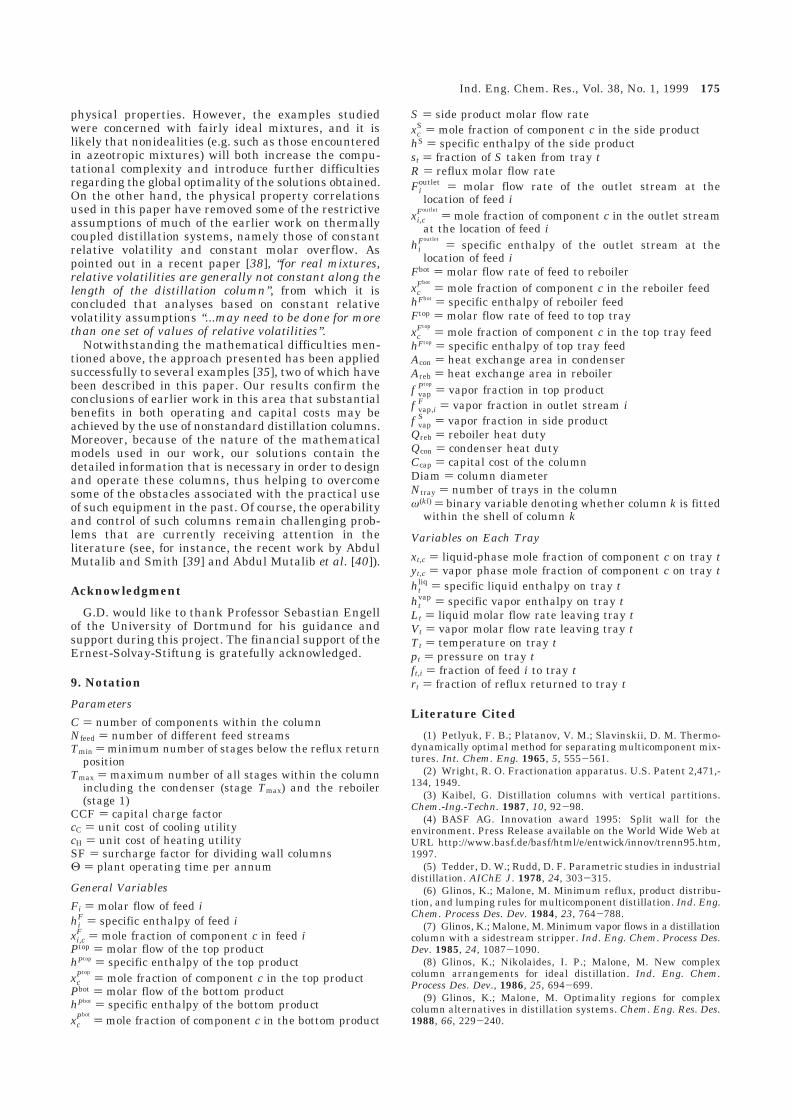
The best design, with a total annualized cost of $112,-560 p.a., is a column with two dividing walls (alternativea). The optimal design and operational parameters forthis solution are displayed in Figure 11.
It is also interesting to note that the most energyefficient alternative is configuration (b). This structure,first proposed by Agrawal [26], involves a main columnsurrounded by two satellite columns. The results indi-cate that this type of arrangement can achieve up toone third energy savings in comparison to conventional
Table 1. Comparison of Different Structural Alternatives for a Required Product Purity of 97%
direct sequence indirect sequence Petlyuk configuration dividing wall column
no. of theoretical trayscolumn no. 1 77 105 63 61column no. 2 108 83 113 113
capital cost ($) 2,680,240 2,583,850 2,564,920 2,136,410reboiler duty (kW)
column no. 1 11 424 13 874 0 0column no. 2 13 614 9 081 17 378 17 682Σ 25 068 22 955 17 378 17 682
operational cost ($ p.a.) 1,284,370 1,177,500 905,220 921,050relative energy savings (%) -9.2 0 24.3 23.0total annualized cost ($ p.a.) 2,356,460 2,211,040 1,931,210 1,775,630relative cost savings (%) -6.6 0 12.7 19.7
Table 2. Comparison of Different Structural Alternatives for a Required Product Purity of 98%
direct sequence indirect sequence Petlyuk configuration dividing wall column
no. of theoretical trayscolumn no. 1 88 90 63 63column no. 2 108 77 113 113
capital cost ($) 2,900,230 2,588,940 2,824,770 2,344,660reboiler duty (kW)
column no. 1 13 218 14 955 0 0column no. 2 13 690 11 876 21 010 20 951Σ 26 908 26 781 21 010 20 951
operational cost ($ p.a.) 1,380,290 1,359,500 1,094,400 1,091,310relative energy savings (%) -0.5 0 21.5 21.8total annualized cost ($ p.a.) 2,540,380 2,395,070 2,224,320 2,029,200relative cost savings (%) -6.1 0 7.2 15.3
Figure 9. Comparison of different structural alternatives for arequired product purity of 90%.
Ind. Eng. Chem. Res., Vol. 38, No. 1, 1999 173
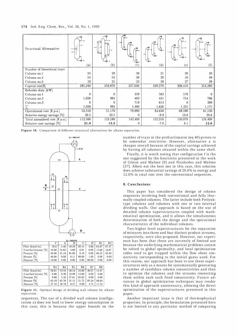
sequences. The use of a divided wall column (configu-ration a) does not lead to lower energy consumption inthis case; this is because the upper bounds on the
number of trays in the prefractionator (eq 40) proves tobe somewhat restrictive. However, alternative a ischeaper overall because of the capital savings achievedby having all columns situated within the same shell.
Finally, it is worth noting that configuration f is theone suggested by the heuristics presented in the workof Glinos and Malone [9] and Nicolaides and Malone[37]. Albeit not the best one in this case, this solutiondoes achieve substantial savings of 20.6% in energy and12.6% in total cost over the conventional sequences.
8. Conclusions
This paper has considered the design of columnsequences involving both conventional and fully ther-mally coupled columns. The latter include both Petlyuk-type columns and columns with one or two internaldividing walls. Our approach is based on the use ofdetailed column superstructures coupled with math-ematical optimization, and it allows the simultaneousdetermination of both the design and the operationalcharacteristics of the individual columns.
Two higher level superstructures for the separationof mixtures into three and four distinct product streams,respectively, were also proposed. However, our experi-ence has been that these are currently of limited usebecause the underlying mathematical problems cannotbe solved to global optimality, and local optimizationcodes tend to get trapped within the flow sheet con-nectivity corresponding to the initial guess used. Forthis reason, our approach has been to use these super-structures only as a means for systematically generatinga number of candidate column connectivities and thento optimize the columns and the streams connectingthem within each such fixed connectivity. Future ad-vances in global optimization techniques may renderthis kind of approach unnecessary, allowing the directoptimization of the superstructures presented in thispaper.
Another important issue is that of thermophysicalproperties. In principle, the formulation presented hereis not limited to any particular method of computing
Figure 10. Comparison of different structural alternatives for alkane separation.
Figure 11. Optimal design of dividing wall column for alkaneseparation.
174 Ind. Eng. Chem. Res., Vol. 38, No. 1, 1999
physical properties. However, the examples studiedwere concerned with fairly ideal mixtures, and it islikely that nonidealities (e.g. such as those encounteredin azeotropic mixtures) will both increase the compu-tational complexity and introduce further difficultiesregarding the global optimality of the solutions obtained.On the other hand, the physical property correlationsused in this paper have removed some of the restrictiveassumptions of much of the earlier work on thermallycoupled distillation systems, namely those of constantrelative volatility and constant molar overflow. Aspointed out in a recent paper [38], “for real mixtures,relative volatilities are generally not constant along thelength of the distillation column”, from which it isconcluded that analyses based on constant relativevolatility assumptions “...may need to be done for morethan one set of values of relative volatilities”.
Notwithstanding the mathematical difficulties men-tioned above, the approach presented has been appliedsuccessfully to several examples [35], two of which havebeen described in this paper. Our results confirm theconclusions of earlier work in this area that substantialbenefits in both operating and capital costs may beachieved by the use of nonstandard distillation columns.Moreover, because of the nature of the mathematicalmodels used in our work, our solutions contain thedetailed information that is necessary in order to designand operate these columns, thus helping to overcomesome of the obstacles associated with the practical useof such equipment in the past. Of course, the operabilityand control of such columns remain challenging prob-lems that are currently receiving attention in theliterature (see, for instance, the recent work by AbdulMutalib and Smith [39] and Abdul Mutalib et al. [40]).
Acknowledgment
G.D. would like to thank Professor Sebastian Engellof the University of Dortmund for his guidance andsupport during this project. The financial support of theErnest-Solvay-Stiftung is gratefully acknowledged.
9. Notation
Parameters
C ) number of components within the columnNfeed ) number of different feed streamsTmin ) minimum number of stages below the reflux return
positionTmax ) maximum number of all stages within the column
including the condenser (stage Tmax) and the reboiler(stage 1)
CCF ) capital charge factorcC ) unit cost of cooling utilitycH ) unit cost of heating utilitySF ) surcharge factor for dividing wall columnsΘ ) plant operating time per annum
General Variables
Fi ) molar flow of feed ihi
F ) specific enthalpy of feed ixi,c
F ) mole fraction of component c in feed iPtop ) molar flow of the top producthPtop ) specific enthalpy of the top productxc
Ptop) mole fraction of component c in the top product
Pbot ) molar flow of the bottom producthPbot ) specific enthalpy of the bottom productxc
Pbot) mole fraction of component c in the bottom product
S ) side product molar flow ratexc
S ) mole fraction of component c in the side producthS ) specific enthalpy of the side productst ) fraction of S taken from tray tR ) reflux molar flow rateFi
outlet ) molar flow rate of the outlet stream at thelocation of feed i
xi,cFoutlet
) mole fraction of component c in the outlet streamat the location of feed i
hiFoutlet
) specific enthalpy of the outlet stream at thelocation of feed i
Fbot ) molar flow rate of feed to reboilerxc
Fbot) mole fraction of component c in the reboiler feed
hFbot ) specific enthalpy of reboiler feedFtop ) molar flow rate of feed to top trayxc
Ftop) mole fraction of component c in the top tray feed
hFtop ) specific enthalpy of top tray feedAcon ) heat exchange area in condenserAreb ) heat exchange area in reboilerf vap
Ptop) vapor fraction in top product
f vap,iF ) vapor fraction in outlet stream i
f vapS ) vapor fraction in side product
Qreb ) reboiler heat dutyQcon ) condenser heat dutyCcap ) capital cost of the columnDiam ) column diameterNtray ) number of trays in the columnω(kl) ) binary variable denoting whether column k is fitted
within the shell of column k
Variables on Each Tray
xt,c ) liquid-phase mole fraction of component c on tray tyt,c ) vapor phase mole fraction of component c on tray tht
liq ) specific liquid enthalpy on tray tht
vap ) specific vapor enthalpy on tray tLt ) liquid molar flow rate leaving tray tVt ) vapor molar flow rate leaving tray tTt ) temperature on tray tpt ) pressure on tray tft,i ) fraction of feed i to tray trt ) fraction of reflux returned to tray t
Literature Cited
(1) Petlyuk, F. B.; Platanov, V. M.; Slavinskii, D. M. Thermo-dynamically optimal method for separating multicomponent mix-tures. Int. Chem. Eng. 1965, 5, 555-561.
(2) Wright, R. O. Fractionation apparatus. U.S. Patent 2,471,-134, 1949.
(3) Kaibel, G. Distillation columns with vertical partitions.Chem.-Ing.-Techn. 1987, 10, 92-98.
(4) BASF AG. Innovation award 1995: Split wall for theenvironment. Press Release available on the World Wide Web atURL http://www.basf.de/basf/html/e/entwick/innov/trenn95.htm,1997.
(5) Tedder, D. W.; Rudd, D. F. Parametric studies in industrialdistillation. AIChE J. 1978, 24, 303-315.
(6) Glinos, K.; Malone, M. Minimum reflux, product distribu-tion, and lumping rules for multicomponent distillation. Ind. Eng.Chem. Process Des. Dev. 1984, 23, 764-788.
(7) Glinos, K.; Malone, M. Minimum vapor flows in a distillationcolumn with a sidestream stripper. Ind. Eng. Chem. Process Des.Dev. 1985, 24, 1087-1090.
(8) Glinos, K.; Nikolaides, I. P.; Malone, M. New complexcolumn arrangements for ideal distillation. Ind. Eng. Chem.Process Des. Dev., 1986, 25, 694-699.
(9) Glinos, K.; Malone, M. Optimality regions for complexcolumn alternatives in distillation systems. Chem. Eng. Res. Des.1988, 66, 229-240.
Ind. Eng. Chem. Res., Vol. 38, No. 1, 1999 175
(10) Carlberg, N. A.; Westerberg, A. W. Temperature-heatdiagrams for complex columns. 2. Underwood’s method for sidestrippers and enrichers. Ind. Eng. Chem. Res. 1989, 28, 1379-1386.
(11) Carlberg, N. A.; Westerberg, A. W. Temperature-heatdiagrams for complex columns. 3. Underwood’s method for thePetlyuk configuration. Ind. Eng. Chem. Res. 1989, 28, 1386-1397.
(12) Annakou, O.; Mizsey, P. Operability investigation of energyintegrated distillation schemes. Hung. J. Ind. Chem. 1996, 24,155-160.
(13) Annakou, O.; Mizsey, P. Rigorous comparative-study ofenergy-integrated distillation schemes. Ind. Eng. Chem. Res. 1996,35, 1877-1885.
(14) Wayburn, T. L.; Seader, J. D. Solutions of systems ofinterlinked distillation columns by differential homotopy-continu-ation methods. In Proceedings of the 2nd Internatinal Conferenceon Found. Computer-Aided Process Design; Westerberg, A. W.;Chien, H. H., Eds.; CACHE Publications: Ann Arbor, Michigan,1984; pp 765-862.
(15) Chavez, R.; Seader, J. D.; Wayburn, T. L. Multiple steady-state solutions for interlinked separation systems. Ind. Eng. Chem.Fundam. 1986, 25, 566-576.
(16) Lin, W-J.; Seader, J. D.; Wayburn, T. L. Computingmultiple solutions to systems of interlinked separation columns.AIChE J. 1987, 33, 886-897.
(17) Rudd, H. Thermal coupling for energy efficiency. TheChemical Engineer 1992, 27, Distillation Supplement.
(18) Lestak, F.; Smith, R, The control of a dividing wall column.Chem. Eng. Res. Des. 71, 1993, 307.
(19) Wolff, E. A.; Skogestad, S. Operation of integrated three-product (Petlyuk) distillation columns. Ind. Eng. Chem. Res. 1995,34: 2094-2103.
(20) Douglas, J. M. Conceptual Design of Chemical Processes;McGraw-Hill Chemical Engineering Series; McGraw-Hill: NewYork, 1988.
(21) Fidkowski, Z. T.; Krolikowski, L. Thermally coupled systemof distillation columns: Optimization procedure. AIChE J. 1986,32, 537-546.
(22) Fidkowski, Z. T.; Krolikowski, L. Minimum energy re-quirements of thermally coupled distillation systems. AIChE J.1987, 33, 643-653.
(23) Kakhu, A. I.; Flower, J. R. Synthesising heat-integrateddistillation sequences using mixed integer programming. Chem.Eng. Res. Des. 1988, 66, 241-254.
(24) Triantafyllou, C.; Smith, R. The design and optimisationof fully thermally coupled distillation columns. Trans. 1nst. Chem.Eng. 1992, 70, 118-132.
(25) Sargent, R. W. H.; Gaminibandara, K. Optimum designof plate distillation columns. In Optimization in Action; Dixon, L.W. C. Ed.; Academic Press: London, 1976; pp 267-314.
(26) Agrawal, R. Synthesis of distillation column configurationsfor a multicomponent distillation. Ind. Eng. Chem. Res. 1996, 35,1059-1071.
(27) Viswanathan, J.; Grossmann, I. E. An alternative modelfor finding the number of trays required for a specified separationobjective. Comput. Chem. Eng. 1993, 17, 949-955.
(28) Viswanathan, J.; Grossmann, I. E. Optimal feed locationsand number of trays for distillation columns with multiple feeds.Ind. Eng. Chem. Res. 1993, 32, 2942-2949.
(29) Smith, E. M. B. On the Optimal Design of ContinuousProcesses. Ph.D. Thesis, University of London, 1996.
(30) Smith, E. M.; Pantelides, C. C. Design of reaction/separa-tion networks using detailed models. Comput. Chem. Eng. 1995,19, S83-S88.
(31) Christiansen, A.; Skogestad, S.; Lien, K. Complex distil-lation arrangements: Extending the Petlyuk ideas. Comput.Chem. Eng. 1997, 21, S237-S242.
(32) Drud, A. S. CONOPT: A system for large scale nonlinearoptimisation - Reference manual; ARKI Consulting and Develop-ment A/S: Bagsværd, Denmark, 1995.
(33) Barton, P. I.; Pantelides, C. C. Modeling of combineddiscrete/continuous processes. AIChE J. 1994, 40, 966-979.
(34) Oh, M.; Pantelides, C. C. A modelling and simulationlanguage for combined lumped and distributed parameter systems.Comput. Chem. Eng. 1996, 20, 611-633.
(35) Dunnebier, G. Case Studies in Optimal Process Design -Separator Networks. Diploma thesis, Lehrstuhl fur Anlagen-steuerungstechnik, Fachbereich Chemietechnik, Universitat Dort-mund, Dortmund, Germany, 1997.
(36) Reid, R. C.; Prausnitz, J. M.; Poling, B. E. The Propertiesof Gases and Liquids; McGraw-Hill: New York, 1986.
(37) Nikolaides, I. P.; Malone, M. Approximate design andoptimization of a thermally coupled distillation with prefraction-ation. Ind. Eng. Chem. Process Des. Dev. 1988, 27, 811-818.
(38) Agrawal, R.; Fidkowski, Z. T. Are thermally coupleddistillation columns always thermodynamically more efficient forternary distillations? Ind. Eng. Chem. Res. 1998, 37, 3444-3454.
(39) Abdul Mutalib, M. I.; Smith, R. Operation and control ofdividing wall distillation columns. part 1: Degrees of freedom anddynamic simulation. Trans. Inst. Chem. Eng. 1998, 76, 308-318.
(40) Abdul Mutalib, M. I.; Zeglam, A. O.; Smith, R. Operationand control of dividing wall distillation columns. part 2: Simula-tion and pilot plant studies using temperature control. Trans. Inst.Chem. Eng. 1998, 76, 319-334.
Received for review May 13, 1998Revised manuscript received October 27, 1998
Accepted October 28, 1998
IE9802919
176 Ind. Eng. Chem. Res., Vol. 38, No. 1, 1999