optimal stiffeners spacing for intermediate link in...
TRANSCRIPT

AUT Journal of Civil Engineering
AUT J. Civil Eng., 1(1) (2017) 39-44DOI: 10.22060/ceej.2017.12345.5176
Optimal Stiffeners Spacing for Intermediate Link in Eccentrically Braced Frame to Increase Energy Dissipation
M. Mojarad, M. Daei*, M. Hejazi
Department of Civil Engineering, University of Isfahan, Isfahan, Iran
ABSTRACT: In general, the behavior of an eccentrically braced frames (EBF) is dependent on the link member characteristics. An efficient link is designed ductile enough to dissipate energy and to prevent the collapse of the frame. Since the link member is reinforced with stiffeners, in order to improve its ductility and plastic deformation capacity, the details of stiffeners design shall be considered more precisely. The existing relationships for web stiffeners spacing in the provisions are based on the behavior of short links with pure shear, while these relationships are applied for intermediate links with shear-bending behavior as well, without any modification. Recent studies have shown the non-conservative stiffeners spacing for some intermediate links. In this study, an optimization algorithm is presented to find the best arrangement of the intermediate link stiffeners. The objective function is the plastic dissipated energy by link before failure and the design variables are locations of stiffeners. The link is simulated under static cyclic loads with finite element software ABAQUS. The heuristic optimization algorithm has been coded in the MATLAB software to find the optimum solutions. The results show that the dissipated energy before failure can be improved significantly by modification of stiffeners spacing.
Review History:
Received: 4 January 2017Revised: 27 February 2017Accepted: 5 March 2017Available Online: 10 March 2017
Keywords:
Eccentrically Braced FrameDissipated EnergyOptimizationLink MemberStatic Cyclic Loading
39
1- IntroductionEccentrically braced frames have been widely used in the buildings because they can provide efficient strength and stiffness similar to concentrically braced frames, while they have a high energy dissipation capacity similar to moment resisting frames [1]. The link member is used as a passive control device that prevents the buckling of braces. The link is the most important member in EBFs. Therefore many analytical and experimental studies have been conducted on the performance of the isolated link member. The link member is reinforced with stiffeners in order to improve its stiffness, ductility, and plastic deformation capacity. Hence, stiffener details are very important in the seismic behaviour of the link.Engelhardt and Okazaki [2] performed experimental tests for different specimens of link with various types of stiffeners. They concluded that the failure can be delayed by changes in intermediate stiffeners details in the intermediate link. Also, they showed that the number of stiffeners in the shear link are conservative, while with one less stiffener, the shear link easily achieves the required plastic rotation. Richards [3] and Galvez [4] also concluded the same results in their studies. Daneshmand and Hosseini [1] investigated the effect of involved parameters on the behavior of links via finite element analysis of intermediate and long links. They showed that the rotation capacity of intermediate links remains almost constant by increasing the stiffener’s thickness. Also, they showed that providing tighter spacing for stiffeners
(increasing the number of stiffeners) or at both sides of the web in the intermediate links can increase their rotation capacity. In the seismic provisions, the inelastic rotation capacity of long links is limited to the small amount of 0.02 radian. Chegeni and Mohebkhah [5] developed the finite element model for the elastoplastic analysis of long links to investigate their rotation capacity. To increase the rotation capacity of the long link, they used the extra stiffeners at the two ends, in addition to those specified in the provisions. They found that a large inelastic rotation capacity for long links can be achieved by placing extra stiffeners.The interest in the optimal design of structural members such as beams, columns, and joints is pervasive throughout the civil engineering over the last two decades. Among different approaches to find the optimal solution, heuristic optimization methods have recently been applied much more. Contrary to classical optimization methods, applying heuristic algorithms show a better robustness in achieving global optimum, while they can be applied for sophisticated finite element models [6]. An optimization method is presented for the design of eccentrically braced frame by Ohsaki and Nakajima [7]. They presented a method for optimizing the locations and thicknesses of the stiffeners of the link member. They used a meta-heuristic method called Tabu search. Through numerical examples, they demonstrated that the dissipated energy can be increased significantly by their proposed optimization algorithm.The numerical and experimental studies conducted on the link beam [3, 8] showed that some of the intermediate link Corresponding author, E-mail: [email protected]

M. Mojarad et al., AUT J. Civil Eng., 1(1) (2017) 39-44, DOI: 10.22060/ceej.2017.12345.5176
40
beams fail before providing the requirements of provisions. The failure of this intermediate links was due to web stiffeners improper spacing. The relationship for web stiffeners spacing is proposed by Popov and Kasai [9] for short links with the shear yielding type of failure (pure shear), while the intermediate links experience significant flexural stress at the both ends of the link and this relationship is applied to the intermediate links without any modification. The results indicated that stiffeners spacing is non-conservative for some intermediate links with shear-bending behaviour [3].In this study, a heuristic optimization algorithm is presented to increase the dissipated energy in the intermediate link. The link is simulated using finite element analysis software ABAQUS Ver. 6.14.1 [10] under the cyclic loading. The precision of the finite element model and cyclic failure index are validated with an experimental specimen of Arce [8]. To find the optimal solution, an evolutionary algorithm called particle swarm optimization (PSO) is modified and applied. The location of stiffeners in the beam is selected as design variables of optimization model and the objective function is the dissipated energy before failure. The failure is determined using cyclic failure index during optimization. Although the proposed algorithms are applied to an intermediate link beam, it is not confined only to this type of link members and it can easily be extended to other types, as well.
2- Results and Discussion2- 1- Definition of cyclic failure index for link memberIn EBFs, the link member is used as the structural fuses. It yields under severe earthquake and dissipates energy by plastic deformation, while the other frame components remain elastic [3]. Thus the link member is an important part in the EBF. In the following, the performance of the link is defined by the cyclic failure index. Ultra-low cyclic fatigue (ULCF) involves extremely large plastic strain and very few (of the order of 10 to 20) cycles to failure. When steel structures are subject to a seismic loading, their failing components experience ultra-low cycle fatigue. Among the proposed methods for predicting crack initiation, the degraded significant plastic strain method (DSPS) is used for predicting ductile failure due to the void growth in the steel constructions [11]. Based on the studies conducted on ductile metals such as steel, under monotonic loading [12], the void growth in a triaxial stress field can be defined as
exp 1.5 mp
e
dR C dR
σε
σ
=
(1)
Where R is the instantaneous void diameter, C is material constant and σm, σe are mean and effective Stress. εp is equivalent plastic strain defined as
0
23
t p pp ij ij dtε ε ε= ∫ (2)
By integrating the above relation and simplify it, the critical value for εp is defined as
exp(1.5 )cr Tε α= (3)Where α is dependent on the material and T is stress triaxiality that is defined as the ratio of mean stress to effective stress (T= σm / σe ).In the monotonic loading, the ductile fracture is always due to the void growth. But in the cyclic loading, there is a void
growth in the tensile and void shrinkage in the compression. Thus equation (1) is rewritten as follows:
( ) ( )sign . .exp 1.5 pdR T C T dR
ε= (4)
According to Kanvinde and Deierlein [13], we define tensile equivalent plastic strain εt when mean stress is positive, and compressive equivalent plastic when εc is negative. The difference between these,that represents the amount of void growth is defined as significant plastic strain ε*.
*t cε ε ε= − (5)
Figure 1 shows the difference between the εp and ε* during a cyclic loading. The critical value for ε* is obtained from equation (4) as
( )* expcr crpε λε ε= − (6)
Therefore, the cyclic failure index is defined as follows and the material is supposed to ductile fracture when FI* reaches 1.0.
*
*crFI εε
∗ = (7)
2- 2- Finite element modelling of link beamThe finite element software ABAQUS is used to model the link member. The general structural behaviour of the link can be simulated in the software to predict the strength reduction due to buckling of link flanges and web. To model the link beam, S4R shell element that has four nodes with six degrees of freedom is used. Reduction integration and linear interpolation are used to improve computational efficiency. The approximate size of elements is selected 20 mm. The material is AStM A992, where the elastic modulus is 200Gpa and poison’s ratio is 0.3. Material properties are based on cyclic coupon testing of A575 steel [14] similar to A992, with a yield stress of 372 Mpa and an ultimate strength of 496 Mpa. The plastic hardening is defined by a nonlinear kinematic hardening law. The kinematic hardening parameters are used
Fig. 1. Equivalent Plastic Strain and Significant Plastic Strain at an Element in Cyclic Loading
Stra
in
Cycle

M. Mojarad et al., AUT J. Civil Eng., 1(1) (2017) 39-44, DOI: 10.22060/ceej.2017.12345.5176
41
according to Richards [3]. The same material is used for web, flanges, and stiffeners.The boundary condition for the isolated link is the same as the one proposed by Richards [3]. As shown in Figure 2, nodes on the left end of the link are restrained against all translational and rotational components except horizontal displacement. Nodes on the right end are restrained against all translational and rotational components except vertical displacement. To verify the procedure of finite element modelling, the results of cyclic tests that performed at University of Texas (UTA) [8] have been used. The specimen UTA 9 has been selected as the sample for verification. It has a wide flange
section W19×36 with five stiffeners of thickness 10mm on one side. Its length is 1219 mm. The loading protocol was used in the test is based on AISC 2002 that is shown in Figure 3. The same loading protocol as an experiment was applied on the right end of the link.Figure 4 shows the inelastic rotation versus shear relationship for UTA 9 specimen in the test and also the result of finite element model. A good agreement between the experiment result and finite element model validates the finite element modelling.
2- 3- Particle swarm optimization (PSO) algorithmThe location of stiffeners in the intermediate link are optimized to increase the dissipated energy before the cyclic failure index reaches 1.0. It is important to select an appropriate algorithm compatible with nonlinear finite element model. We used a heuristic approach called particle swarm optimization (PSO). PSO is a nature-inspired algorithm developed by Kennedy and Eberhart [15]. The swarm is composed of N particles in D-dimensional search space, where each particle represents a possible solution to an optimization problem. The social forces calculated based on both memories of each individual and also the knowledge gained by the swarm leads the movement of particles toward an optimum solution. The basic algorithm of PSO is defined as follows:• Step 1, in the algorithm each particle is characterized by
two parameters, position, and velocity. These parameters are initialized randomly throughout the design space in the first iteration of the algorithm.
• Step 2, for each particle, the objective function value can be evaluated using its position and then each particle retains the memory of its best position, called a local best. Hitherto,this local best represents the best solution obtained by the particle.
• Step 3, as a similar manner, the swarm keeps its best
Fig. 2. Boundary Condition on Model Link [3]
Fig. 3. AISC 2002 Loading Protocol [3]
Fig. 4. Deformed Geometry and Link Shear Versus Inelastic Rotation
a) Experimantal Model [8] b) Finite Element Model
__
M. Mojarad et al., AUT J. Civil Eng., 1(1) (2017) 39-44, DOI: 10.22060/ceej.2017.12345.5176
42
solution, called the global best. Then the velocity of particles is updated based on local and global best according to equation (8). This equation is presented to update velocity of ith particle vi(t), which belongs to tth iteration. In this equation, vi(t) is the current velocity vector of ith particle (for (t-1)th iteration), xi(t-1)th is the current position of ith particle (for (t-1)th iteration), Pbi and Pg are local best of ith particle and global best of swarm so far, respectively, r1 and r2 are selected randomly between (0,1) and c1 and c2 are stochastic weighting values that indicate the degree of confidence to the memory of ith particle and experience of the swarm as a whole, respectively.
( ) ( ) ( )( )( )( )
1 1
2 2
1 1
1i i bi i
g i
v t v t c r P x t
c r P x t
= − + − −
+ − −(8)
• Step 4, finally, the updated position of particle is calculated based on according to the following equation
( ) ( ) ( )1i i ix t x t v t= − + (9)
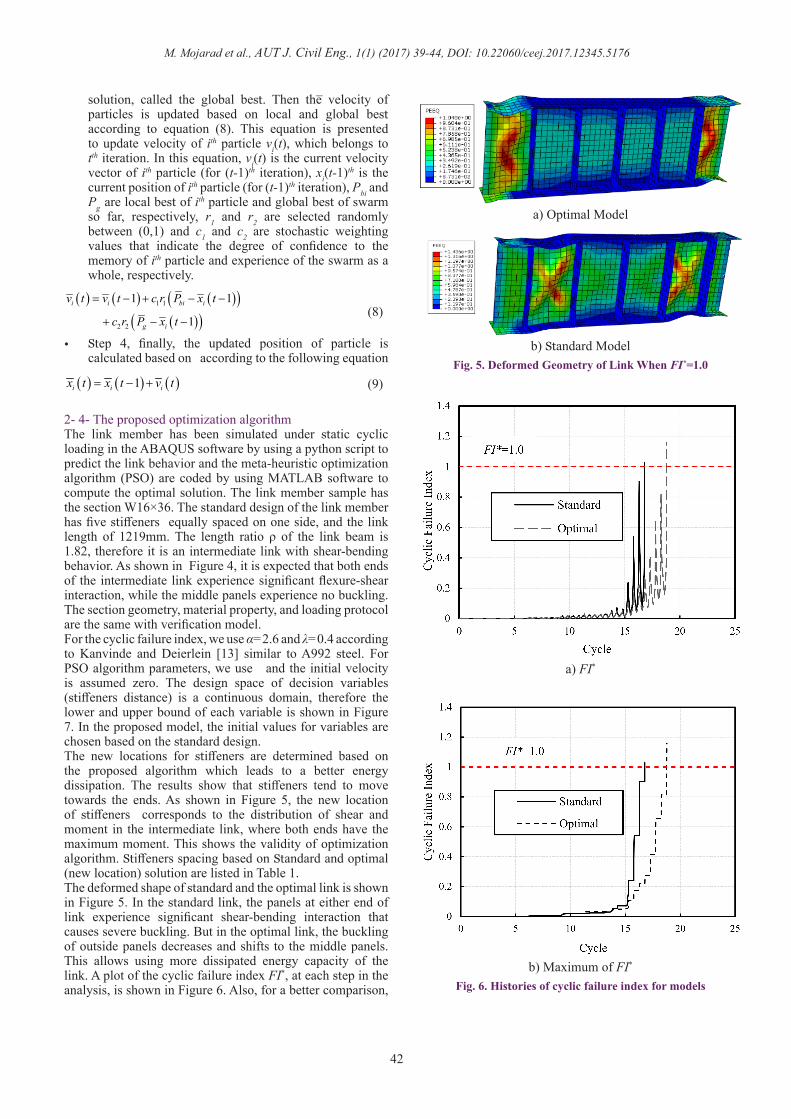
2- 4- The proposed optimization algorithmThe link member has been simulated under static cyclic loading in the ABAQUS software by using a python script to predict the link behavior and the meta-heuristic optimization algorithm (PSO) are coded by using MATLAB software to compute the optimal solution. The link member sample has the section W16×36. The standard design of the link member has five stiffeners equally spaced on one side, and the link length of 1219mm. The length ratio ρ of the link beam is 1.82, therefore it is an intermediate link with shear-bending behavior. As shown in Figure 4, it is expected that both ends of the intermediate link experience significant flexure-shear interaction, while the middle panels experience no buckling. The section geometry, material property, and loading protocol are the same with verification model.For the cyclic failure index, we use α=2.6 and λ=0.4 according to Kanvinde and Deierlein [13] similar to A992 steel. For PSO algorithm parameters, we use and the initial velocity is assumed zero. The design space of decision variables (stiffeners distance) is a continuous domain, therefore the lower and upper bound of each variable is shown in Figure 7. In the proposed model, the initial values for variables are chosen based on the standard design.The new locations for stiffeners are determined based on the proposed algorithm which leads to a better energy dissipation. The results show that stiffeners tend to move towards the ends. As shown in Figure 5, the new location of stiffeners corresponds to the distribution of shear and moment in the intermediate link, where both ends have the maximum moment. This shows the validity of optimization algorithm. Stiffeners spacing based on Standard and optimal (new location) solution are listed in Table 1.The deformed shape of standard and the optimal link is shown in Figure 5. In the standard link, the panels at either end of link experience significant shear-bending interaction that causes severe buckling. But in the optimal link, the buckling of outside panels decreases and shifts to the middle panels. This allows using more dissipated energy capacity of the link. A plot of the cyclic failure index FI*, at each step in the analysis, is shown in Figure 6. Also, for a better comparison,
_
a) Optimal Model
b) Standard ModelFig. 5. Deformed Geometry of Link When FI*=1.0
a) FI*
b) Maximum of FI* Fig. 6. Histories of cyclic failure index for models

M. Mojarad et al., AUT J. Civil Eng., 1(1) (2017) 39-44, DOI: 10.22060/ceej.2017.12345.5176
43
the maximum so far of FI* is plotted for a standard and optimal solution. As shown obviously, the optimal link withstands about two cycles more than standard form. Also, histories of plastic dissipated energy of the standard and the
optimal solution are shown in Figure 9. Table 1 shows the maximum shear Vmax and dissipated energy Ep when FI* reaches 1.0. Optimization results show dissipated energy Ep can be improved up to 43% by optimization.
3- ConclusionIn this study, an optimization model is proposed to find the optimal locations of stiffeners for intermediate links subject
to static cyclic loading. For this purpose, the link member has been simulated in the ABAQUS software, while the meta-heuristic PSO algorithm is coded by using MATLAB. The finite element model and the algorithm of PSO are combined using Python script available in ABAQUS. In the proposed optimization model, the objective function is the dissipated energy and the constraint is defined based on the failure index.The following conclusions are drawn from the studies of stiffeners spacing for the intermediate link to increase energy dissipation:1. The intermediate links experience severe buckling in
their outside panels due to shear-bending yielding. Since the relationships of web stiffeners spacing in the provisions are based on the behaviour of the short link which yields in shear, applying the same concept for spacing of stiffeners in the intermediate links cannot be the optimal design. Due to this reason, the failure of some intermediate links has also been observed in the previous studies.
2. The proposed optimization algorithm can find a new arrangement for stiffeners so that it will lead to an increase in energy dissipation through delaying buckling. Although the optimization algorithm presented in this paper is not confined to intermediate links and it can easily be extended to other types of links, the proposed algorithm can be more efficient for intermediate links. For example, the dissipated energy increase 43% during the optimization of an intermediate link with the section W16×36, while the maximum shear is constant.
3. The optimization results show that stiffeners tend to move towards the ends of intermediate links, which is compatible with the distribution of shear and moment in this type of link.
4. The cyclic plastic analysis of link in the ABAQUS is time-consuming and finding optimum arrangement of stiffeners without using optimization algorithms requires many trial and error experiments, therefore applying the PSO algorithm, as a meta-heuristic algorithm for optimization, is completely efficient and it is the significant feature of the proposed method to find the best design of the link, which leads to the best seismically performance.
References[1] A. Daneshmand, B.H. Hashemi, Performance of
intermediate and long links in eccentrically braced frames, Journal of Constructional Steel Research, 70 (2012) 167-176.
[2] T. Okazaki, M.D. Engelhardt, Cyclic loading behavior of EBF links constructed of AStM A992 steel, Journal of constructional steel Research, 63(6) (2007) 751-765.
[3] P.W. Richards, Cyclic stability and capacity design of steel eccentrically braced frames, University of California, San Diego, 2004.
[4] P. Gálvez, Investigation of factors affecting web fractures in shear links, University of Texas at Austin, 2004.
Model Stiffeners Spacing (as) Cycle No. Vmax (kN) Ep (kN.m) Increased Energy
Standard 6@203mm 16.68 192 781.1 -----Optimal 152, 178, 280, 280,178, 152 mm 18.77 191.5 1118.3 43%
Table 1. Optimization Results
Fig. 7. Design Space for Link Stiffeners
Fig. 8. Forces Distribution in the Link
Fig. 9. Histories of Dissipated Energy

M. Mojarad et al., AUT J. Civil Eng., 1(1) (2017) 39-44, DOI: 10.22060/ceej.2017.12345.5176
44
[5] B. Chegeni, A. Mohebkhah, Rotation capacity improvement of long link beams in eccentrically braced frames, Scientia Iranica. Transaction A, Civil Engineering, 21(3) (2014) 516.
[6] N.D. Lagaros, L.D. Psarras, M. Papadrakakis, G. Panagiotou, Optimum design of steel structures with web openings, Engineering Structures, 30(9) (2008) 2528-2537.
[7] M. Ohsaki, T. Nakajima, Optimization of link member of eccentrically braced frames for maximum energy dissipation, Journal of Constructional Steel Research, 75 (2012) 38-44.
[8] G. Arce, Impact of higher strength steels on local buckling and overstrength of links in eccentrically braced frames, University of Texas at Austin, 2002.
[9] K. Kasai, E.P. Popov, Cyclic web buckling control for
shear link beams, Journal of Structural Engineering, 112(3) (1986) 505-523.
[10] ABAQUS, Dassault Systémes Simulia Corp., in, 2014.[11] H. Amiri, A. Aghakouchak, S. Shahbeyk, M. Engelhardt,
Finite element simulation of ultra low cycle fatigue cracking in steel structures, Journal of Constructional Steel Research, 89 (2013) 175-184.
[12] J.R. Rice, D.M. Tracey, On the ductile enlargement of voids in triaxial stress fields*, Journal of the Mechanics and Physics of Solids, 17(3) (1969) 201-217.
[13] A.M. Kanvinde, Micromechanical simulation of earthquake-induced fracture in steel structures, 2004.
[14] E. Kaufmann, B. Metrovich, A. Pense, Characterization of cyclic inelastic strain behavior on properties of A572 Gr. 50 and A913 Gr. 50 rolled sections, (2001).
[15] R. Eberhart, J. Kennedy, A new optimizer using particle swarm theory, in: Micro Machine and Human Science,
1995. MHS’95., Proceedings of the Sixth International Symposium on, IEEE, 1995, pp. 39-43.
Please cite this article using:
M. Mojarad, M. Daei, M. Hejazi, “Optimal Stiffeners Spacing for Intermediate Link in Eccentrically Braced Frame
to Increase Energy Dissipation”, AUT J. Civil Eng., 1(1) (2017) 39-44.
DOI: 10.22060/ceej.2017.12345.5176