optimal tuning of a lqr controller for an inverted ... · pdf fileinverted pendulum using the...
TRANSCRIPT

Optimal Tuning of a LQR Controller for an
Inverted Pendulum Using the Bees Algorithm
Muhammed Arif Sen and Mete Kalyoncu Department of Mechanical Engineering, Faculty of Engineering, University of Selçuk, Konya, Turkey
Email: {marifsen, mkalyoncu}@selcuk.edu.tr
Abstract—The paper presents the design of a Linear
Quadratic Regulator (LQR) controller for an Inverted
Pendulum (IP) system using The Bees Algorithm (BA) to
provide optimal parameters of LQR. Inverted Pendulum is
a typical highly nonlinear and unstable system and widely
used as a benchmark for testing different control techniques
in control theory. LQR is an optimal control method that
can achieve the closed loop control of multivariable
dynamical systems with minimum control effort. In LQR
controller design, state (Q) and control (R) weighting
matrices are main design parameters which are defined by
designer using trial and error method in general. Automatic
tuning of the weighting matrices with an optimization
algorithm ensure expected efficiency from LQR controller.
Also the technique consider to design of time domain
specifications like overshoot, rise time, settling time, and
steady state error. In this paper, The Bees Algorithm
optimizes the weighting matrices of LQR controller be able
to move the cart in reference input with the minimum
deflection of the pendulum’s angular position. The tuning
aim is to minimize the objective function which consists of
time domain responses of system in MATLAB/Simulink.
The paper gives the simulation results obtained for the
system demonstrating the efficiency and robustness of the
proposed design method of LQR controller.
Index Terms—the bees algorithm, LQR controller tuning,
optimal control, inverted pendulum
I. INTRODUCTION
The single Inverted Pendulum (IP) system with two
degrees of freedom (the angle of the pendulum and the
linear position of the cart) constitutes the theoretical
background of SEGWAY since it is highly unstable. The
stabilizing of the system is significant an issue in the field
of control engineering to verify modern control theories.
There are presented variety methods for Inverted
Pendulum; classical methods such as PID and LQR
controllers and artificial intelligent control techniques
such as Fuzzy Logic Control [1].
The performance of model based controllers depend on
selection and tuning technique of one or more design
parameters which are usually determined with using trial
and error techniques. Inverted pendulum is one of the
benchmark problems of control theory for illustration and
comparison of optimization methodologies. There are
different optimization algorithm to obtain optimally LQR
Manuscript received September 22, 2015; revised December 2, 2015.
controller for stable motion of Inverted Pendulum such as
Memetic Algorithm (MA) [2], Multi-Objective
Differential Evolution Algorithm (MODE) [3], Genetic
Algorithm (GA) [4], Quantum Particle Swarm
Optimization Algorithm (QPSO) [5] and Artificial Bee
Colony Algorithm (ABC) [6].
Following a definition of the system and LQR
controller in sections 1-2, The Bees Algorithm is briefly
described in section 3. In section 4, the paper gives the
simulation results of the Inverted Pendulum
demonstrating the of the optimal LQR controller design.
II. MODELLING OF THE INVERTED PENDULUM SYSTEM
Figure 1. Model and free body diagram of IP system
Fig. 1 shows that the general model of the Inverted
Pendulumsystem [7]. The model consists of a free
moving pendulum with the mass m and length l located in
the vertical direction to the cart with mass M, which is
free to move in the x direction when a force F is applied
to the system.
TABLE I. PARAMETERS OF THE IP SYSTEM
Symbol Parameter Value Unit
M Mass of the cart 0.5 [kg]
m Mass of the pendulum 0.2 [kg]
b Friction of the cart 0.1 [N/m/s]
l Length of the pendulum 0.3 [m]
I Inertia of the pendulum 0.006 [kgm2]
g Gravity 9.81 [m/s2 ]
As show in Fig. 1, the free body diagram of the system.
From the free body diagram, the following linearized
(about =π, represents a small angle from the
vertical upward direction) dynamic equations in the
384©2016 Journal of Automation and Control Engineering
Journal of Automation and Control Engineering Vol. 4, No. 5, October 2016
doi: 10.18178/joace.4.5.384-387
horizontal direction and vertical direction are determined
in Eq. (1) and Eq. (2). The dynamic equations can be
represented in a state-space form and an output equation
as stated in Eq. (3) and Eq. (4). The parameters of the
Inverted Pendulum system are shown in Table I.
(𝐼 + 𝑚𝑙2)�̈� − 𝑚𝑔𝑙𝜙 = 𝑚𝑙�̈� (1)
(𝑀 + 𝑚)�̈� + 𝑏𝑥 ̇ − 𝑚𝑔�̈� = 𝑢 (2)
[
�̇��̈��̇�
�̈�
] = [
0 1 0 00 −0.1818 2.6727 00 0 0 10 −0.4545 31.1818 0
] [
𝑥�̇�𝜙
�̇�
] + [
01.8182
04.5455
] 𝑢 (3)
𝑦 = [1 0 0 10 0 1 0
] [
𝑥�̇�𝜙
�̇�
] + [00
] 𝑢 (4)
III. LQR CONTROLLER DESIGN FOR THE IP SYSTEM
LQR control problem may be stated to find the optimal
input u(t) = −Kx(t) sequence that minimizes the quadratic
performance index (J) which is defined in Equation (5).
Where Q= diag [q1…qn] and R = diag [q1…qm] are the
symmetric, positive state and control weighting matrices.
The state feedback gain matrix is defined as K = (R-1
BT
P). Where P is the unique symmetric, positive semi-
definite solution to the algebraic Riccati Equation as
depicted PA+ATP+Q−PBR
-1 B
TP = 0.
𝐽 = ∫ [𝑥𝑇𝑄𝑥 + 𝑢𝑇𝑅𝑢]𝑑𝑡∞
0 (5)
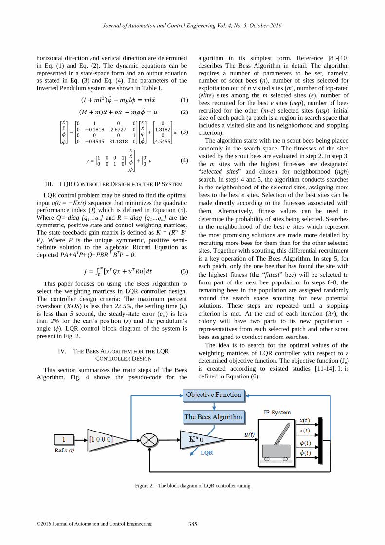
This paper focuses on using The Bees Algorithm to
select the weighting matrices in LQR controller design.
The controller design criteria: The maximum percent
overshoot (%OS) is less than 22.5%, the settling time (ts)
is less than 5 second, the steady-state error (ess) is less
than 2% for the cart’s position (x) and the pendulum’s
angle (ϕ). LQR control block diagram of the system is
present in Fig. 2.
IV. THE BEES ALGORITHM FOR THE LQR
CONTROLLER DESIGN
This section summarizes the main steps of The Bees
Algorithm. Fig. 4 shows the pseudo-code for the
algorithm in its simplest form. Reference [8]-[10]
describes The Bess Algorithm in detail. The algorithm
requires a number of parameters to be set, namely:
number of scout bees (n), number of sites selected for
exploitation out of n visited sites (m), number of top-rated
(elite) sites among the m selected sites (e), number of
bees recruited for the best e sites (nep), number of bees
recruited for the other (m-e) selected sites (nsp), initial
size of each patch (a patch is a region in search space that
includes a visited site and its neighborhood and stopping
criterion).
The algorithm starts with the n scout bees being placed
randomly in the search space. The fitnesses of the sites
visited by the scout bees are evaluated in step 2. In step 3,
the m sites with the highest fitnesses are designated
“selected sites” and chosen for neighborhood (ngh)
search. In steps 4 and 5, the algorithm conducts searches
in the neighborhood of the selected sites, assigning more
bees to the best e sites. Selection of the best sites can be
made directly according to the fitnesses associated with
them. Alternatively, fitness values can be used to
determine the probability of sites being selected. Searches
in the neighborhood of the best e sites which represent
the most promising solutions are made more detailed by
recruiting more bees for them than for the other selected
sites. Together with scouting, this differential recruitment
is a key operation of The Bees Algorithm. In step 5, for
each patch, only the one bee that has found the site with
the highest fitness (the “fittest” bee) will be selected to
form part of the next bee population. In steps 6-8, the
remaining bees in the population are assigned randomly
around the search space scouting for new potential
solutions. These steps are repeated until a stopping
criterion is met. At the end of each iteration (itr), the
colony will have two parts to its new population -
representatives from each selected patch and other scout
bees assigned to conduct random searches.
The idea is to search for the optimal values of the
weighting matrices of LQR controller with respect to a
determined objective function. The objective function (Je)
is created according to existed studies [11-14]
defined in Equation (6).
Figure 2. The block diagram of LQR controller tuning
t is . I
385©2016 Journal of Automation and Control Engineering
Journal of Automation and Control Engineering Vol. 4, No. 5, October 2016

𝐽𝑒 = (5𝑋𝑡𝑟 + 2,5𝑋𝑡𝑠 + 𝑋𝑡𝑝 + 10𝑋𝑚𝑎𝑥 + 104𝑋𝑒𝑠𝑠) +
(20𝜙𝑛𝑜𝑟𝑚 + 2𝜙𝑡𝑠 + 20𝜙𝑡𝑝 + 170𝜙𝑚𝑎𝑥 + 2.106𝜙𝑒𝑠𝑠) (6)
where tr is the rise time, ts is the settling time, tp is the
peak time, max is the maximum overshoot, ess is the
steady state error, norm is angle of matrix norm. The
constant values are weight factors.
Figure 3. The block diagram of LQR controller tuning
TABLE II. THE BEES ALGORITHM PARAMETERS
n m e nep nsp ngh itr
50 20 10 20 15 0.01 100
TABLE III. OPTIMIZATION RANGE OF PARAMETERS
Q1 Q2 Q3 Q4 R1
Max. 100 10 1000 10 2
Min. 0 0 0 0 0
V. SIMULATION RESULTS
The parameters of The Bees Algorithmare
demonstratedin Table II and the optimization range of
LQR parameters are set as in Table III. In Fig. 2, the
block diagram of LQR controller for the Inverted
Pendulumis modelled in MATLAB/Simulink. After
optimization, the tuned weighting matrices of the LQR
controller are obtained as Q = diag [22.733, 7.993,
46.269, 3.431] and R= diag [0.1671] and the state
feedback gain matrix is K = [-4.078, -5.216, 31.275,
6.107] and the control system is run for 7 seconds in
Simulink.
Fig. 4 show that the graphical results obtained by the
LQR controller tuned by The Bees Algorithm for the
angular displacement of the pendulum and the linear
displacement of the cart. The LQR controller responses of
system’s outputs in time domain specification are
presented in Table IV.
Figure 4. The cart’s position and the Pendulum’s angle response
TABLE IV. CONTROL PERFORMANCE OF THE CART’S POSITION AND
THE PENDULUM’S ANGLE
Cart Position Pendulum Angle
Rise Time (tr) 1.51 [s] ---
Settling Time (ts) 3.02 [s] 3.5 [s]
Peak Time (tp) 6.9 [s] 0.135 [s]
Overshoot (OS) 0.1 % Max. 3.12 [deg]
Min. -7.75 [deg]
Steady State Error
(ess) 0 [m] 0 [deg]
The Bees Algorithm was programmed in MATLAB
and run on an Intel(R) Core(TM) i7-4700HQ CPU 2.40
GHz PC with 16.0 GB memory. The algorithm run for
100 iterations to find a minimum value for the objective
function (Equation (6)) with the settings given for the
algorithm. Computing time of the algorithm is 1188.7
second and the ratio of CPU usage is 12%. The Bees
Algorithm complexity analysis and comparing with other
optimization algorithm are extensively investigated in
benchmarking studies [10].
Figure 5. The performance analysis of the bees algorithm for the LQR controller design
386©2016 Journal of Automation and Control Engineering
Journal of Automation and Control Engineering Vol. 4, No. 5, October 2016

Because of the algorithm is used for a LQR controller
design as a diversity method in this paper, it was not
compared to other algorithms. So the performance
analysis of The Bees Algorithm to design of a LQR
controller for the Inverted Pendulum system is presented
in Fig. 5.
VI. CONCLUSION
The tuning of LQR controller for an unstable Inverted
Pendulum with The Bees Algorithm is reported in this
paper. The Bees Algorithm is a diversity method to select
optimal weighting matrices of LQR controller. Q and R
matrices are tuned using The Bees Algorithm to minimize
the angle of the pendulum and the positioning errors of
the cart. The control responses of system in time
specification are given in Table IV. The results obtained
show that the optimal LQR controller produced with the
tuning method is very successfully to control of the
system within controller design criteria. Moreover, the
optimization technique proposed in this study ensures to
tuning the expected specifications of time domain
response of Inverted Pendulum system in optimization. It
can improve performances in terms of control accuracy
and speed of response by changing the objective function,
the optimization parameters and ranges.
ACKNOWLEDGMENT
This paper was arisen from M. Arif Sen’s MSc thesis
named “Design and Optimization of a Fuzzy Logic Based
Controller for A Two-Wheeled Robot by Using The Bees
Algorithm”. This work was supported by the Coordinator
ship of Selçuk University Scientific Research Projects.
REFERENCES
[1] P. Ponce, A. Molina, and E. Alvarez, “A review of intelligent
control systems applied to the inverted-pendulum problem,”
American Journal of Engineering and Applied Sciences, vol. 7, no. 2, pp. 194-240, 2014.
[2] J. Zhang, L. Zhang, and J. Xie, “Application of memetic algorithm
in control of linear inverted pendulum,” in Proc. 2011 IEEE International Conference on Cloud Computing and Intelligence
Systems, China, 2011, pp. 103-107.
[3] I. B. Tijani, R. Akmeliawati, and A. I. Abdullateef, “Control of an
inverted pendulum using mode-based optimized LQR controller,”
in Proc. 2013 IEEE 8th Conference on Industrial Electronics and
Applications , Australia, 2013, pp. 1759-1764. [4] C. Wongsathan and C. Sirima, “Application of GA to design LQR
controller for an inverted pendulum system,” in Proc. IEEE Int.
Conf. Robotics and Biomimetics, Thailand, 2008, pp. 951-954. [5] K. Hassani and W.S. Lee, “Optimal tuning of linear quadratic
regulators using quantum particle swarm optimization,” in Proc.
International Conference of Control, Dynamic Systems and Robotics, no. 59, Ottawa, Canada, 2014.
[6] B. Ata and R. Coban, “Artificial bee colony algorithm based linear quadratic optimal controller design for a nonlinear inverted
pendulum,” in Proc. International Conference on Advanced
Technology &Sciences, Antalya, Turkey, 2014, pp. 47-52. [7] Information. [Online]. Available:
http://ctms.engin.umich.edu/CTMS
[8] D. T. Pham, et al, “The bees algorithm–A novel tool for complex optimization problems,” in Proc. the 2nd Virtual International
Conference on Intelligent Production Machines and Systems, 2006,
pp. 454-459. [9] D. T. Pham, A. Ghanbarzadeh, E. Koc, S. Otri, S. Rahim, and M.
Zaidi, The Bees Algorithm Technical Note, Manufacturing
Engineering Centre, Cardiff University, UK., 2005. [10] D. T. Pham and M. Castellani, “Benchmarking and comparison of
nature-inspired population-based continuous optimization
algorithms,” Soft Computing-A Fusion of Foundations, Methodologies and Applications, vol. 18, pp. 871-903, 2013.
[11] D. T. Pham, E. Koc, M. Kalyoncu, and M. Tınkır, “Hierarchical
PID controller design for a flexible link robot manipulator using the bees algorithm,” in Proc. 6th International Symposium on
Intelligent Manufacturing Systems, Sakarya, Turkey, 2008, pp.
757-765. [12] D. T. Pham and M. Kalyoncu, “Optimization of a fuzzy logic
controller for a flexible single-link robot arm using the bees
algorithm,” Cardiff University, UK, 2009. [13] A. A. Fahmy, M. Kalyoncu, and M. Castellani, “Automatic design
of control systems for robot manipulators using the bees
algorithm,” in Proc. the Institution of Mechanical Engineers, Part I, Journal of Systems and Control Engineering, vol. 226, no. 4,
2012, pp. 497-508.
[14] M. A. Şen and M. Kalyoncu, “Optimization of a PID controller for an inverted pendulum using the bees algorithm,” in Proc. Int.
Conference on Mechatronics and Automation Science, Applied
Mechanics and Material Journal, Section: Manufacturing Science and Technology VI, vol. 789-790, Paris, France, 2015, pp. 1039-
1044.
Muhammed Arif ŞEN was born in 1987, Konya, Turkey. He received the B.S. and M.S.
degrees in Mechanical Engineering from
Selçuk University, Konya, Turkey, in 2010, and 2014, respectively. He currentlycontinue
Ph.D. education at Selçuk UniversityFaculty
of Engineering, as research assistant.His research interests include,Control Theory,
System Dynamics,Mechatronics Systems,
Mobile Robotics, Modeling and Simulation, MATLAB Simulation, Controller Design, The Bees Algorithm and
Optimization.
Mete Kalyoncu received the M.S. and Ph.D.
degrees in Mechanical Engineering from Selçuk University, Konya, Turkey, in 1993
and 1998, respectively. He is currently an
Associate Professor in the Mechanical Engineering Department, Selçuk University.
His research interests include, System
Dynamics and Control, Mechatronics, Mechanical Vibration, Robotic, Industrial
Design, Fuzzy Logic Control, Modeling of
Systems and Simulation, Controller Design, The Bees Algorithm and Optimization.
387©2016 Journal of Automation and Control Engineering
Journal of Automation and Control Engineering Vol. 4, No. 5, October 2016