optimisation of water usages in thermal · pdf fileash pond water recovery expected to be ......
TRANSCRIPT

1
OPTIMISATION OF WATER USAGES IN THERMAL
POWER PLANTS AND A STUDY ON DRY COOLING
SYSTEM
S. K. Thakur, Dr. L. D. Papney,Chief Engineer (I/C), Director,TE&TD Division, CEA TE&TD Division, CEA
CONFERENCE ON WATER OPTIMISATION IN THERMAL POWER PLANTS
India Habitat Centre, N. Delhi12- 13 June, 2013
2
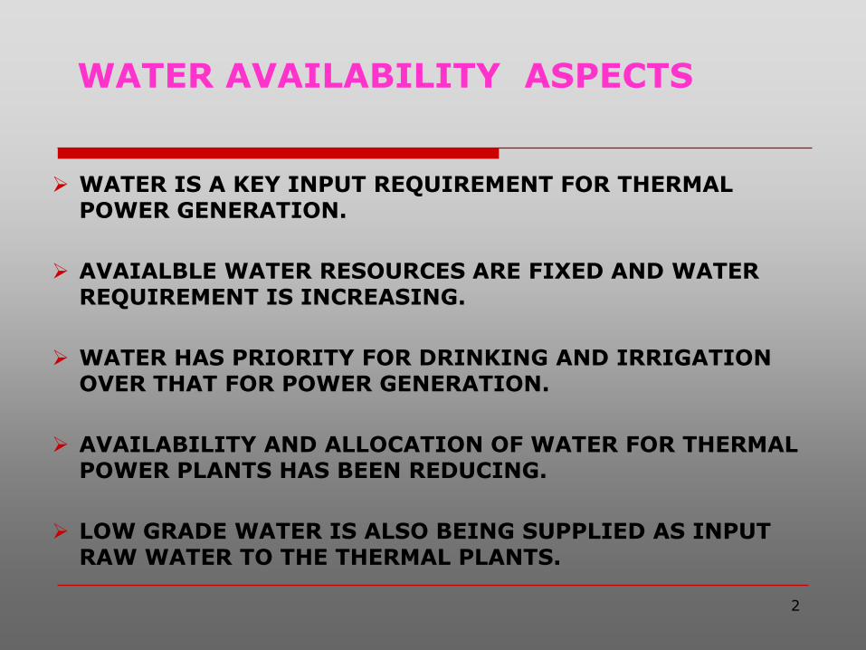
WATER AVAILABILITY ASPECTS
WATER IS A KEY INPUT REQUIREMENT FOR THERMAL POWER GENERATION.
AVAIALBLE WATER RESOURCES ARE FIXED AND WATER REQUIREMENT IS INCREASING.
WATER HAS PRIORITY FOR DRINKING AND IRRIGATION OVER THAT FOR POWER GENERATION.
AVAILABILITY AND ALLOCATION OF WATER FOR THERMAL POWER PLANTS HAS BEEN REDUCING.
LOW GRADE WATER IS ALSO BEING SUPPLIED AS INPUT RAW WATER TO THE THERMAL PLANTS.

3
NEED FOR OPTIMISING/ MINIMISING WATER CONSUMPTION IN THERMAL
PLANTS
THERMAL CAPACITY ADDITION PROJECTED AT ABOUT 15000 MW/ANNUM FOR NEXT TWO DECADES.
LARGE NUMBER OF SITES REQUIRED WITH AVAILABILTY OF ADEQUATE WATER.
DIFFICULTIES BEING FACED IN SELECTION OF NEW SITES IN DIFFERENT STATES DUE TO WATER SCARCITY.
CONSTRAINTS IN AVAILABILITY OF SWEET WATER FOR COASTAL SITES.
WATER OPTIMISATION/ MINIMISATION IS NECESSARY
TO ENHANCE PLANT SITING OPTIONS

4
TYPICAL WATER USES IN COAL BASED THERMAL POWER PLANTS
COOLING OF CONDENSER AND SECONDARY COOLING OF PHEs IN ECW SYSTEM.
POWER CYCLE MAKE UP.
WET ASH DISPOSAL.
COAL DUST SUPPRESSION.
AIR CONDITIONING AND VENTILATION.
OTHER USES VIZ. POTABLE USE, PLANT WASHING, GARDENING.

5
COOLING WATER SYSTEM
Once through system:
Permissible for coastal sites with temperature rise of 70C over temperature of receiving water body.
Closed cycle open recirculation system using cooling towers:
Requires make up water to compensate for loss of water due to evaporation, drift and blow down.
Blow down is required to maintain a desired level of COC in CW system.

6
CT MAKE-UP & BLOWDOWN
CT make-up water, M = E . C
(C-1)
Blow down water, B = E - D
(C-1)
Where E = Evaporation,
D = Drift,
C = COC of CW system

7
VARIATION OF CT MAKE UP WITH COC (500 MW UNIT)
Description
Cycle of Concentration (C)
1.6 2.0 3.0 4.0 5.0
Evaporation, m3/h
(%)
1020
(1.7)
1020
(1.7)
1020
(1.7)
1020
(1.7)
1020
(1.7)
Drift, m3/h
(%)
30
(0.05)
30
(0.05)
30
(0.05)
30
(0.05)
30
(0.05)
Blow down, m3/h
(%)
1670
(2.783)
990
(1.65)
480
(0.8)
310
(0.517)
225
(0.375)
Make up, m3/h
(%)
2720
(4.533)
2040
(3.4)
1530
(2.55)
1360
(2.267)
1275
(2.125)

8
BROAD FEATURES GOVERNING PLANT WATER REQUIREMENT
Source/ quality of raw water.
Type of CW system.
Quality of coal.
Plant design aspects.
Use of dry fly ash.
Treatment/ reuse of waste water.

9
WATER REQUIREMENT TRENDS
Earlier water was taken as an assured input.
Plant used to have liberal considerations and high design margins.
Plant consumptive water with cooling tower used to be about 7 m3/h/MW without ash water recirculation and 5 m3/h/MW with ash water recirculation.
In recent past, consumptive water requirement used to be taken as 3.5- 4m3/h per MW.

10
CONSIDERATIONS FOR REDUCTION OF PLANT WATER REQUIREMENT
New plants to progressively achieve 100% utilisation
of fly ash by 4th year of plant operation.
COC of 5 for CW system operation
Clarifier sludge water and filter backwash to be recycled.
Boiler blowdown to be used as part of CT make up.
Power cycle make up as 2% of BMCR flow.
Waste water to be used for coal dust suppression and gardening.
Dry cooling system as per constraint in availability of raw water.
11
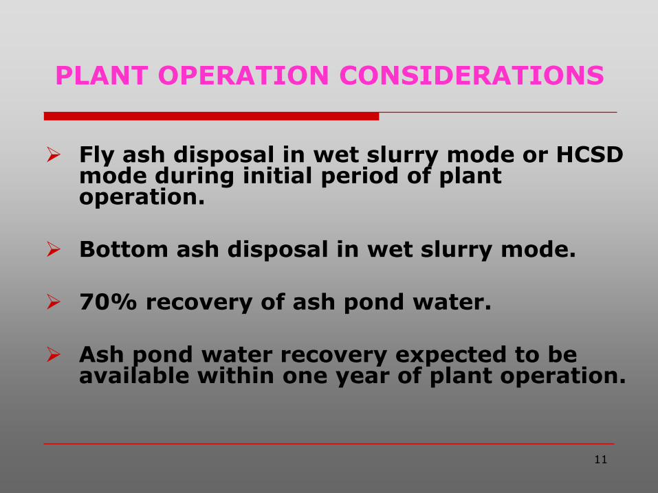
PLANT OPERATION CONSIDERATIONS
Fly ash disposal in wet slurry mode or HCSD mode during initial period of plant operation.
Bottom ash disposal in wet slurry mode.
70% recovery of ash pond water.
Ash pond water recovery expected to be available within one year of plant operation.
12
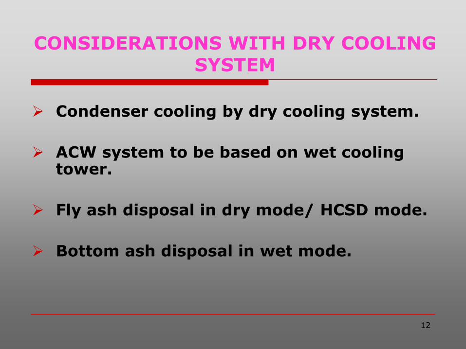
CONSIDERATIONS WITH DRY COOLING SYSTEM
Condenser cooling by dry cooling system.
ACW system to be based on wet cooling tower.
Fly ash disposal in dry mode/ HCSD mode.
Bottom ash disposal in wet mode.

13
CASES CONSIDERED
Inland power plant with wet cooling tower.
Inland power plant with dry coolingsystem.
Coastal power plant based on sea water.

14
WATER BALANCE DIAGRAM 2 X 500 MW COAL BASED WITH WET COOLING TOWER
15
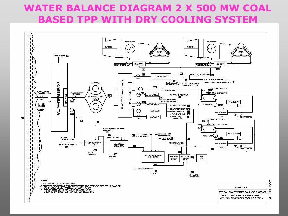
WATER BALANCE DIAGRAM 2 X 500 MW COAL BASED TPP WITH DRY COOLING SYSTEM
16
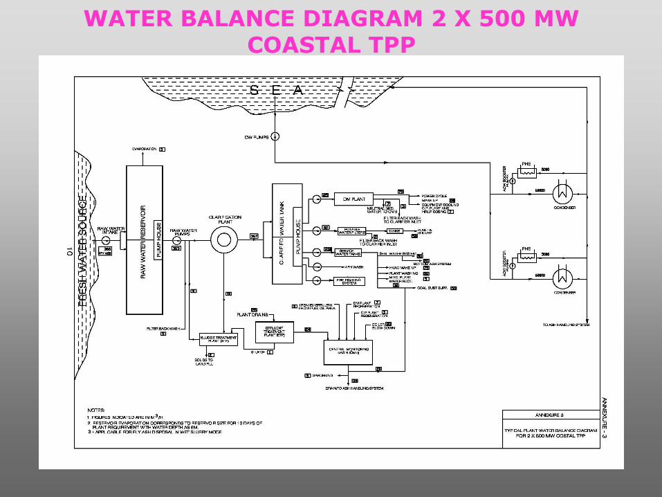
WATER BALANCE DIAGRAM 2 X 500 MW COASTAL TPP
17
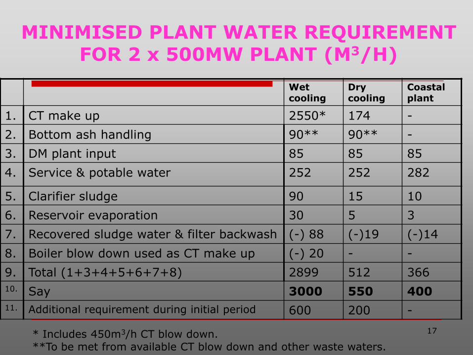
MINIMISED PLANT WATER REQUIREMENT FOR 2 x 500MW PLANT (M3/H)
Wet cooling
Dry cooling
Coastal plant
1. CT make up 2550* 174 -
2. Bottom ash handling 90** 90** -
3. DM plant input 85 85 85
4. Service & potable water 252 252 282
5. Clarifier sludge 90 15 10
6. Reservoir evaporation 30 5 3
7. Recovered sludge water & filter backwash (-) 88 (-)19 (-)14
8. Boiler blow down used as CT make up (-) 20 - -
9. Total (1+3+4+5+6+7+8) 2899 512 366
10. Say 3000 550 400
11. Additional requirement during initial period 600 200 -
* Includes 450m3/h CT blow down.**To be met from available CT blow down and other waste waters.

18
WASTE WATER GENERATION IN 2 x 500MW PLANT (M3/H)
Wet cooling
Dry cooling
Coastal plant
1. Unused CT blow down/ boiler blow down 350 - 20
2. DM plant & CPU regeneration 10 10 10
3. Treated effluent of plant drains etc. 58 31 29
4. Waste water utilized for coal dust suppression/ ash disposal
(-)50
(coal dust suppression)
(-)22
(ash disposal)
(-)20
(coal dust suppression)
5. Waste water utilized for gardening (-)5 (-)5 (-)5
6. Waste water to be disposed from CMB
(1+2+3+4+5)
363 14 34

19
SUMMARY ON PLANT WATER REQUIREMENT:WET COOLING SYSTEM
3.6m3/h per MW during initial period of plant operation with fly ash disposal in wet mode (without ash water recovery).
3 m3/h per MW after recovery of ash pond water, expected to begin within one year of plant operation.
If fly ash is disposed in dry mode/ HCSD mode, 3m3/h per MW will be adequate for plant operation right from beginning.

20
SUMMARY ON PLANT WATER REQUIREMENT: DRY COOLING SYSTEM
Fly ash disposal in dry mode:
0.75 m3/h per MW during initial period of plant operation without recovery of bottom ash water.0.55 m3/h per MW after recovery of bottom ash water, expected to begin within one year of plant operation.
Fly ash disposal in HCSD mode:
0.9 m3/h per MW during first year of plant operation. 0.7 m3/h per MW in subsequent period.
About 80% reduction in plant water requirementwhen using dry cooling system.

21
SUMMARY ON PLANT WATER REQUIREMENT:COASTAL PLANTS
Fresh water requirement 0.4 m3/h per MW.
Sea water to be used for process cooling and ash disposal.
In case, desalination plant is installed, required fresh water shall be generated from sea water.

22
STUDY ON DRY
CONDENSER COOLING
SYSTEM

23
KEY FEATURES OF DRY COOLING SYSTEM
Operate on the basis of sensible cooling with ambient dry bulb temperature as reference temperature.
Steam condensation temperature = ambient dbt + initial temperature difference (ITD), governed by size of cooling equipment.
Turbine back pressure achieved is higher and power output of the unit is reduced.
24
TYPES OF DRY COOLING SYSTEM
Cont’d 2
Direct dry cooling: Air cooled condenser
LP turbine exhaust steam is directly cooledinside a system of finned tube bundles byambient air using forced draft fans.
No Terminal temperature difference (TTD) isinvolved.

25
TYPES OF DRY COOLING SYSTEM
Cont’d 3
Indirect dry cooling: Surface condenser
Steam is cooled in a surface condenser bycirculating water which in turn, inside asystem of finned tube bundles, is cooled byambient air using fans or a natural drafttower.
Terminal temperature difference (TTD) isinvolved.

26
TYPES OF DRY COOLING SYSTEM
Cont’d 4
Indirect dry cooling: Jet condenser
Steam is cooled by direct mixing with DM water in ajet condenser. A part of mixed hot DM water is sentto power cycle and rest is pumped to a system offinned tube bundles for cooling by ambient air usinga natural draft tower.
Negligible TTD is involved.
Hydraulic turbine can be used to recover pressurehead of circulating water.
27
TYPES OF DRY COOLING SYSTEM
Hybrid system
Employs both wet cooling and dry cooling system provisions:
• When water is not available, plant is operated with dry cooling system.
• When water is available, cooling system is switched over to wet cooling system.

28
AIR COOLED CONDENSER WITH FANS

29
INDIRECT DRY COOLING WITH SURFACE CONDENSER

30
INDIRECT DRY COOLING WITH JET CONDENSER- HELLER SYSTEM
Steam Turbine
DC Condenser
Boiler Feed Water
CoolingTower
Recovery Turbine
CW Pump
Water to AirHeat Exchanger
Dry

31
HYBRID (DRY/WET) COOLING SYSTEM

32
DRY COOLING SYSTEM ANALYSIS METHODOLOGIES
Same unit output with higher size BTG plant.
Same size BTG plant with lower unit output for dry cooling system plant.

33
CASE STUDY
Study has been carried out for a 500 MW size unit plant considering same size BTG plant for wet cooling and dry cooling.
Inputs for wet cooling system obtained from M/s NTPC.
Inputs for dry cooling system obtained from:
M/s SPX/Thermax for ACC and
M/s GEA-EGI/Energo for Heller system
Inputs on BTG system obtained from M/s BHEL.

34
DESIGN INPUT DATA FOR DRY COOLING SYSTEM
Design ambient dbt, oC 38
ITD, oC 20 22 24 26
Steam condensation temp. oC 58 60 62 64
Condenser pressure, ata (a) 0.18 0.2 0.22 0.24
Unit output, MW 464.6 463.7 462.8 461.9
% short fall 7.1 7.3 7.4 7.6
Design condenser heat load,
million Kcal/h (MWt)
581.7
(676.5)
582.1
(677)
582.7
(677.7)
583.6
(678.7)
Size of BTG: 500 MW with wet cooling; 0.1 ata(a) back pressure
35
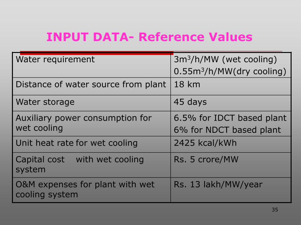
INPUT DATA- Reference Values
Water requirement 3m3/h/MW (wet cooling)
0.55m3/h/MW(dry cooling)
Distance of water source from plant 18 km
Water storage 45 days
Auxiliary power consumption for wet cooling
6.5% for IDCT based plant
6% for NDCT based plant
Unit heat rate for wet cooling 2425 kcal/kWh
Capital cost with wet cooling system
Rs. 5 crore/MW
O&M expenses for plant with wet cooling system
Rs. 13 lakh/MW/year

36
INPUT DATA- Tariff Calculations
Debt/ equity ratio 70 : 30
Interest rate 11%
Return on equity 15.5%
Plant PLF 85%
Fuel escalation 6 %
O&M escalation 5%
Discount rate 9.35%
Depreciation rate 5.28%

37
OPTIONS CONSIDERED
1. Load centre station with coal GCV of 4000 kcal/kg and coal cost of Rs. 2200 per ton.
2. Pit head station with coal GCV of 3600 kcal/kg and coal cost of Rs. 1000 per ton.
Wet cooling:NDCT IDCT
Dry cooling:ACCHellar system

38
RESULTS OF THE STUDY
Reduction in plant output by about 7%.
Increase in capital cost per MW of the plant by about 10 to 14%.
Increase in specific fuel consumption and specific CO2 emission by about 7%.
Auxiliary power consumption for plant with ACC about 6.8% as compared to 6.5% for reference plant with IDCT.
O&M expenses marginally lower at about Rs. 12 lakh/year per MW over reference of 13 lakh/year per MW for wet cooling plant.
39
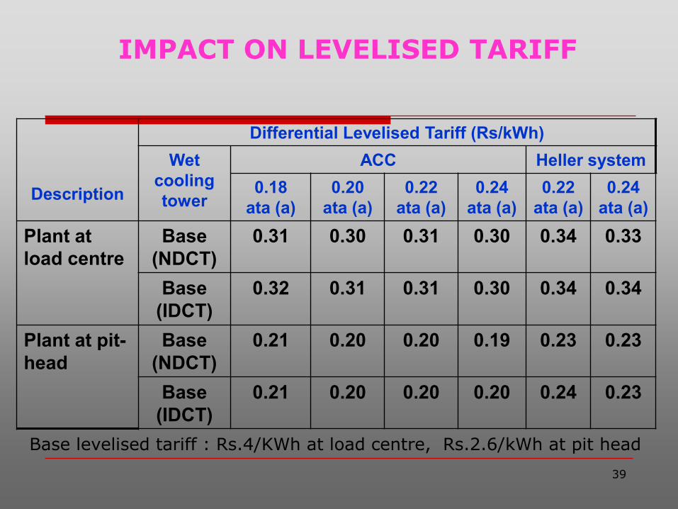
IMPACT ON LEVELISED TARIFF
Description
Differential Levelised Tariff (Rs/kWh)
Wet
cooling
tower
ACC Heller system
0.18
ata (a)
0.20
ata (a)
0.22
ata (a)
0.24
ata (a)
0.22
ata (a)
0.24
ata (a)
Plant at
load centre
Base
(NDCT)
0.31 0.30 0.31 0.30 0.34 0.33
Base
(IDCT)
0.32 0.31 0.31 0.30 0.34 0.34
Plant at pit-
head
Base
(NDCT)
0.21 0.20 0.20 0.19 0.23 0.23
Base
(IDCT)
0.21 0.20 0.20 0.20 0.24 0.23
Base levelised tariff : Rs.4/KWh at load centre, Rs.2.6/kWh at pit head
40
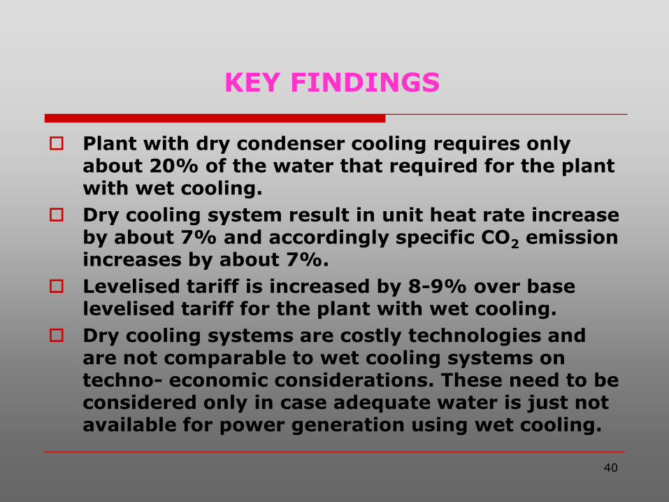
KEY FINDINGS
Plant with dry condenser cooling requires only about 20% of the water that required for the plant with wet cooling.
Dry cooling system result in unit heat rate increase by about 7% and accordingly specific CO2 emission increases by about 7%.
Levelised tariff is increased by 8-9% over base levelised tariff for the plant with wet cooling.
Dry cooling systems are costly technologies and are not comparable to wet cooling systems on techno- economic considerations. These need to be considered only in case adequate water is just not available for power generation using wet cooling.

41