optimization of blended composite wing panels using smeared stiffness technique and lamination...
TRANSCRIPT

7/27/2019 Optimization of Blended Composite Wing Panels Using Smeared Stiffness Technique and Lamination Parameters
http://slidepdf.com/reader/full/optimization-of-blended-composite-wing-panels-using-smeared-stiffness-technique 1/11
Optimization of Blended Composite Wing Panels Using
Smeared Stiffness Technique and Lamination Parameters
Dianzi Liu*
and Vassili V. Toropov†
University of Leeds, LS2 9JT, UK
Ming Zhou‡
Altair Engineering Inc., 2445 McCabe Way, Suite 100, Irvine, CA 92614, USA
and
David C. Barton§
and Osvaldo M. Querin**
University of Leeds, LS2 9JT, UK
The smeared stiffness-based method is examined for finding the best stacking sequence of
laminated composite wing structures with blending and manufacturing constraints. In this
method, numbers of plies of the pre-defined angles (0, 90, 45 and -45 degrees) are design
variables, buckling, strain and ply angle percentages are constraints and the material volume
is the objective function at the global level. The ply shuffling to satisfy global blending and
manufacturing constraints is performed at the local level to match zero values of lamination
parameters. The latter requirement is due to the ply angle homogeneity through the stack
that is assumed in the top level optimization. This integrated process utilizing the smeared
stiffness technique and lamination parameters is demonstrated by the optimization of the root
part of a generic aircraft wing structure. The local level optimization can be seen as a
postprocessing phase for determining the detailed ply-book of the laminate.
Nomenclature
A = in-plane stiffness matrix
D = out-of-plane stiffness matrix
h = thickness of a laminated panel
i = panel number
n = number of plies N max
t = ply thickness
= maximum number of plies of the same angle placed sequentially in the stack
ijQ 6,2,1, = ji= items in the transformed reduced stiffness matrix,
iU = material invariants, 5,,2,1 =i
z = distance of the ply position from the laminate mid planeV = lamination parameters
*PhD student, School of Mechanical Engineering, University of Leeds, LS2 9JT, UK, AIAA Student Member.
†Professor of Aerospace and Structural Engineering, School of Civil Engineering and School of Mechanical
Engineering, University of Leeds, LS2 9JT, UK, AIAA Associate Fellow.‡
VP, FE Solvers and Optimization, Altair Engineering Inc., 2445 McCabe Way, Suite 100, Irvine, CA 92614, USA§Professor of Solid Mechanics, School of Mechanical Engineering, University of Leeds, LS2 9JT, UK.
**Senior Lecturer, School of Mechanical Engineering, University of Leeds, LS2 9JT, UK, AIAA Senior Member.

7/27/2019 Optimization of Blended Composite Wing Panels Using Smeared Stiffness Technique and Lamination Parameters
http://slidepdf.com/reader/full/optimization-of-blended-composite-wing-panels-using-smeared-stiffness-technique 2/11
I. Introduction
tacking sequence optimization of laminated composite structures is very important for achieving the material’s
required mechanical characteristics such as in-plane, flexural and bucking behaviour 1-4
Kristinsdottir et al
. For the manufacturability
of laminates, maintaining ply continuity (or blending) between adjacent panels is required. This requirement also
allows to reduce stress concentrations at the interface of adjacent laminates while achieving structural integrity of the
whole structure. Due to the industrial requirements and practical manufacturing considerations, symmetric and
balanced laminates with ply orientations of 0, 90, 45 and -45 degrees are focused on in this work.5
1, = jit
.introduced the methodology of ‘blending’ to ensure that a laminated composite panel is
manufacturable. This blending methodology divides the panel into individual regions for analysis. In each region the
loads were constant, but the loads could vary between regions. Given this set of load conditions, an indicator that
identified the key region (heaviest loaded region) from which plies originated and could cover a number of adjacent
regions was determined. Thus, a ply could be stopped between adjacent regions or added at the load concentrations.Once the ply was dropped, it was not allowed to be added back into the panel. This way of continuously dropping
plies from the key region was called the ‘greater-than-or-equal to’ blending rule. Also in that paper two different
blending schemes were introduced to incorporate optimization formulations in the design process: the first scheme
used binary thickness as a design variable, such as in the optimization formulation. ‘1’ means that ply i with
certain fibre angle θ existed in the region j . Thus, switching the binary thickness of each ply ensured the blending
requirement of adjacent regions in a panel; the second scheme used integer distance as a design variable to denote
how many regions a ply occupied, such as 2, = jid in the optimization formulation. This equation means that a ply
i of fibre orientation θ extends through the first two regions starting from the given row j . A 12-region sandwich
keel panel was successfully optimized with these two blending schemes to achieve a blended design.
Other techniques were developed for blending of laminated composite structure in Gürdal’s research group in
2002-2003. Soremekun et al.6
introduced concepts of sub-laminates (plies shared between several panels) and design
variable zones (groups of panels covered by the same sub-laminates) for blended panel optimization. A two-stepdesign procedure was implemented in a GA optimization code. This approach kept the total thickness of each panel
obtained in the first (global) optimization step (with a margin of 2 to 4 plies) but redefined the stack composition for
the sub-laminates in the second (local) optimization step. FEA was used in the first optimization step and, then again
during the second optimization step for every stack arrangement considered by a GA. Adams et al.7
To measure the ply continuity between adjacent panels in the laminated composite design process, two continuity
indices were defined in the paper by Liu and Haftka
developed a
distributed GA within a parallel processing environment with migration to obtain blended designs for specified local panel loads. Each individual panel was designed by a different processor in a parallel environment. The populations
representing stacking sequences of each local panel were allowed to evolve in parallel and the adjacent populationswere used to produce blended design by migrating the best candidate from one population to another. A metric was
introduced to evaluate similarities between individuals within a population and those in the set of migrants from
adjacent panels. With this approach blended solutions could be obtained but the required computing effort could
become very large for realistic multiple panel laminated composite structures.
8: material composition continuity and stacking sequence
continuity. Using a two-level optimization strategy9
)45,45,90,0( −
, the weight of laminated composite wing structure could be
minimized subject to strain and buckling constraints. At the global level, numbers of plies of each
orientation for every panel were determined and the measure of material composition continuity
was developed as a function of the total thickness of layers of the same orientation for the adjacent panels and the
total thickness of the reference panel or the thicker panel. This measure, used at the global level, was independent of
the detailed stacking sequence of plies between the adjacent panels. At the local level, the stacking sequence of plies
in each panel was determined by a permutation GA to maximize the buckling load factor. The measure of stacking
sequence continuity was developed in terms of the number of continuous layers between two adjacent panels and the
total thickness of the referenced panel. The definition of a continuous ply between two adjacent panels required thattwo layers of the same orientation can not be separated by more than one truncated layer in the thickness direction.
With these two new measures of ply continuity, an 18-panel wing box structure was optimized and the blended
design was obtained.
A guide based design by GA with two blending methods, inward and outward blending, was developed by Adams
et al.10
S
to improve the ply continuity between adjacent panels with given local loading constraints. The guide based
approach defined a single laminate (called the guide laminate) used as a template for the stacking sequence of all the
panels. Stacking sequences of all the laminates were obtained by taking a certain number of plies from the top or the
bottom of this guide laminate to guarantee a fully blended solution at all stages of optimization. If the layers extracted
from the top of the guide laminate were placed at the outmost stack of each panel, this was called outer blending. If
the layers extracted from the bottom of the guide laminate were placed on the inside of the mid plane for each panel,
this was called inner blending. In the optimization process, the design variables defined the stacking sequence of the
guide laminate and the number of layers to be kept from the guide laminate to represent the configuration of layups in

7/27/2019 Optimization of Blended Composite Wing Panels Using Smeared Stiffness Technique and Lamination Parameters
http://slidepdf.com/reader/full/optimization-of-blended-composite-wing-panels-using-smeared-stiffness-technique 3/11
each panel. An eighteen panel horse-shoe design problem was optimized with the global blending requirement. Later,
Adams et al.11
applied the guide based design approach to a more realistic case of the laminated wing box design
problem. This was achieved by coupling the local loads for each panel with a global level analysis in terms of
different stacking sequences and number of layers with each fibre orientation for individual panels. The need for
global/local iterations in the optimization process of the blended laminated wing box design affected the
computational efficiency. In 2007, Seresta et al.12
developed a local improvement operator by stripping or adding one
ply per panel at the local level to prevent large jumps in the local in-plane panel loads thus considerably reducing therequired computating effort. Using this idea, no expensive global finite element analysis was needed to compute the
new in-plane loads distribution when local stiffness of each panel was changed by the local improvement. Only one
global finite element analysis for each individual in the population was used and the local panel analysis for buckling
and strength constraints needed to be checked repetitively in the local level. The same blending scheme was imposed
by the means of a guide-based GA. Ijsselmuiden et al.13,14
developed a multi-step framework for blended design of
composite structures with a guide-based GA to reduce the computating effort for the evaluation of local panel
buckling constraints during the blending optimization. In the first step, flexural lamination parameters and thickness
of each panel are design variables, while buckling constraints were applied in the minimum weight optimization of the panel. At this stage, the sensitivity matrix was created, which indicated the sensitivity of the inverse of the panel
buckling load multiplier. In the second step, the sensitivity matrix was used to approximate the structural response,
which was initially used as an objective function for the guide-based GA. In order to guarantee the local buckling
constraint satisfaction for all blended panels, the sensitivity matrix corresponding to the converged guide-based GA
optimum design was used to generate a successive approximation of the buckling load, which was used as aconstraint while minimizing the structural weight. Van Campen et al.
15proposed two new blending definitions to
generalize guide based blending and implemented these two definitions with a multi-chromosomal GA. In the first
definition, if all the layers from the thinner panel continue in the thicker one regardless of their position through the
thickness of the laminate, these two adjacent panels were considered completely blended. The second definition,
which was less restrictive than the first, stipulates that two adjacent panels are considered to be perfectly blended if
there were no dropped edges in the physical contact. A multi-chromosome GA for presenting each individual(possible solution for the design) was further developed on the basis of a guide-based GA. The multiple
chromosomes were composed of a laminate (guide) chromosome and a panel chromosome (a binary chromosome in
which the binary genes acted as switching genes: value 1 for the use of the layer in the guide and value 0 for
switching the ply off). With the use of the panel chromosome, the stacking sequence of each panel could be
effectively obtained by switching layers of the guide stack on and off. Seresta et al.16
presented a robust and efficient
way to implement a GA framework for the blended design of multiple laminated composite structures. Based on the
work of Van Campen et al.15
Liu and Butler
, a multi-chromosomal GA was used to impose the blending constraint. The advantage of this new representation of an individual is that a separate chromosome (panel chromosome) defines the number of
plies to be kept for each panel and the length of the that chromosome is equal to the number of panels. The standard
GA crossover operator was used to arrive at the minimum number of plies whilst there is no need for the local
improvement operator to impose the blending constraint.17
A different approach was developed by Liu and Krog
attempted to achieve global ply continuity by a bi-level design method for practical designs of
composite stiffened panels that were subject to compression loads and lateral pressure. At the global (panel) level
optimization, design variables used were skin thickness and width of skins, along with stiffeners and flanges. The
objective function was to minimize the mass of the stiffened panels with buckling and strength constraints. The
laminate percentages were specified as 50% for plies of 0º, 40% for ±45º, and 10% for 90º during the panel level
optimization. At the laminate (local) level optimization, the stacking sequence of the components (skin, stiffener, and flange) that maximizes the buckling load factor are determined subject to the manufacturing rules. To achieve the
blended panel design satisfying the industrial manufacturability requirements, a stacking sequence table (tabular
method) based on the repeated use of pre-defined sublaminate as a stacking template for shuffling plies of thecomponents, was used in the local level optimization. A small reduction in buckling capacity was incurred when the
tabular stacking sequence method was applied to achieve the blended panel design.18
Recently, two bi-level composite optimization procedures were investigated by Liu et al.
to identify a laminate stacking sequence in individual wing panels that satisfied inter-panel continuity constraints. First, the Airbus composite box optimization tool COMBOX
was used at the global level to optimize all skin and stringer dimensions and laminate ply percentages in a single
optimization run. Given these results, a set of ply layout cards were generated from rounding the continuous laminate
dimensions and ply percentages. This process of card generation can be seen as a post-processing method for
identifying stacking sequence of ply layouts. In this method, a conventional stacking sequence identification problem
is transformed into a problem of shuffling a set of global ply layout cards. Then, a permutation GA was applied to
find an optimal card sequence to satisfy the local stacking sequence rules for each panel.19
to seek the best
stacking sequence of laminated composite wing structures with blending and manufacturing constraints. The two
examined approaches are: a smeared stiffness-based method, that aims to neutralize the stacking sequence effects onthe buckling performance, and a lamination parameter-based method, that uses lamination parameters as design

7/27/2019 Optimization of Blended Composite Wing Panels Using Smeared Stiffness Technique and Lamination Parameters
http://slidepdf.com/reader/full/optimization-of-blended-composite-wing-panels-using-smeared-stiffness-technique 4/11
variables to formulate the membrane stiffness matrix A and bending stiffness matrix D . The advantage of the
smeared stiffness-based method is that it avoids a stack optimization at the local (bottom) level by performing a
quicker post-processing function of ply shuffling. The advantage of the lamination parameter-based approach is that
there is no need to check whether the strength or buckling constraints have been violated as long as the lamination
parameters obtained after the local level optimization match the given lamination parameter values that came from
the top level optimization. Then, Liu et al.20
In this paper, the smeared stiffness-based approach is used for the optimization of stacking sequence of laminated
composite wing structure. The numbers of plies of the fibre orientations (0, 90, 45 and -45 degrees) are the design
variables and constraints are imposed on buckling, strain and ply percentages. The material volume is the objective
function at the global level. Then, a permutation GA is used to shuffle the layers to minimize the difference between
the values of computed lamination parameters for a current stack and the ones coming from the top level, which arezeros due to homogeneity through the thickness of the laminate assumed in the top level optimization. This is
embedded into a blending procedure applied at this level to achieve the global ply continuity. This integrated process
of smeared stiffness technique and lamination parameters is demonstrated by the optimization of a generic aircraft
wing structure, in which only the root part is considered to reduce the computational effort. The optimization
software OptiStruct by Altair Engineering
further developed a multi-objective function for the local level
optimization, which is composed of three criteria indices: lamination parameters match index, stack homogeneityindex, and 90º ply angle jump index to maximize the stack homogeneity, one of the layup rules in the laminated
composite design.
21
II. Smeared Stiffness-Based Method
is used for the top level optimization of the laminated composite wing
structure. The local level optimization can be seen as a postprocessing phase in which the detailed ply-book of thelaminate is obtained while guaranteeing the satisfaction of strain and buckling constraints.
In order to minimize the total material volume of all panels, the numbers of plies of each fibre orientation
)45,45,90,0( − in the panels are defined as design variables in the optimization problem subject to the buckling
constraints and constraints on the principal strain values. Industrial requirements and practical manufacturing
considerations led to the assumption that only symmetric and balanced laminates with ply
orientations 0 ,
90 ,
45 and 45− need to be investigated. Therefore, only half the number of plies of each orientation
is given in all numerical results presented in this paper. Also, as the number of plies of 45 angle ( 45n ) is always
equal to the number of plies of 45− degree angle ( 45−n ) for balanced laminates, the number of pairs of 45± plies is
presented as 45±n . At the local level, maximization of ply compatibility will be achieved by the optimization of the
ply stacking sequence whereas the overall laminate thickness remains constant as it is fixed after the top level
optimization.
Smeared stiffness-based method 19
A
is an approach that aims to neutralize the stacking sequence effects on the
buckling performance by considering homogeneous sections with quasi-isotropic layups. This method is used to
calculate the matrices and D of laminates without determining a stacking sequence. Hence no pre-defined stacking
sequence of plies is needed in the top level weight optimization. According to the classical laminate theory (CLT)22
A
,
the matrices and D can be formulated as:
=
66
2622
161211
Asym
A A
A A A
A,
=
66
2622
161211
Dsym
D D
D D D
D(1)
where
.6,2,1,
,6,2,1,
2
2
2
2
2
==∫=
==∫=
−
−
jidz zQ D
jidzQ A
h
hijij
h
hijij
Lamination parameters were first introduced by Tsai et al.23
A. It is known that the stiffness matrices and D are
governed by 12 lamination parameters and five material parameters. For orthotropic symmetric and balanced laminates, the number of independent lamination parameters can be reduced to eight. Introducing lamination
parameters, the elements of the bending stiffness matrix D can be expressed as:

7/27/2019 Optimization of Blended Composite Wing Panels Using Smeared Stiffness Technique and Lamination Parameters
http://slidepdf.com/reader/full/optimization-of-blended-composite-wing-panels-using-smeared-stiffness-technique 5/11
.
0020
0020
1000
0100
001
001
12
5
4
3
2
1
42
42
3
3
31
31
3
26
16
66
12
22
11
−
−
−
−
=
U
U
U
U
U
h
D
D
D
D
D
D
D D
D D
D
D
D D
D D
ξ ξ
ξ ξ
ξ
ξ
ξ ξ
ξ ξ
(2)
∫
=
−
2
2
2
3],4,3,2,1[ ]4sin,4cos,2sin,2[cos12 i
i
h
h
Di dz z
hθ θ θ θ ξ (3)
where D indicates bending effects, D
]4,3,2,1[ξ is lamination parameters related with bending stiffness matrix D ,
i is the panel number,
ih is the total thickness of the panel i ,
θ is the ply angle.
In this work, to ensure that lamination parameters are strictly positive, they are introduced in the followingformulation:
∫
+=
−
2
2
2
3
],4,3,2,1,0[ ]4sin,4cos,2sin,2cos,1[2
1i
i
h
hi
Di dz z
hV θ θ θ θ
(4)
In the formulae above the values of 321,0 += DiV , hence the lamination parameters related to the out-of-plane
stiffness matrix can be written as:
.]4cos,2sin,2[cos2
12
2
2
3
],3,2,1[ ∫
+==
−
i
i
h
hi
Di
Di dz z
hV θ θ θ V
(5)
Based on smeared stiffness concept, for a homogeneous material the relationship between A and D can be
formulated as:
.122hAD =
(6)
Thus, it can be seen that for a homogeneous stack ]1,1,1[],3,2,1[ == Di
Di V V .
The application of the smeared stiffness-based approach to the concept optimization of composite structures was
demonstrated by Zhou and Fleury24
. Zhou et al.25
recently developed a comprehensive optimization technology,
which is a three-phase process, implemented in the commercial software OptiStruct since release 9.021
A bi-level optimization process is used in research presented in this paper. At the top level, the volume of all plies
is the objective function and the design variables are the numbers of plies of each orientation. Both buckling and
strain constraints are considered. Altair’s OptiStruct software is used for the top level optimization. Then, at the local
(bottom) level a stacking sequence optimization is performed to minimize the difference between the values of
computed lamination parameters
. In the first
phase free-size optimization with manufacturing constraints is applied to a laminate representation that consists of
groups of plies of the same orientation. According to the obtained thicknesses, the thickness distribution is interpreted into ply patches, for which size optimization is performed in the second phase. In the final phase, for each panel the
stacking sequence of individual plies is determined while satisfying all manufacturing constraints. The process is
automated and flexible, but no ply compatibility between adjacent laminates (blending) was considered so far. Also,
it can happen that buckling constraints could be violated in the final design phase. If a constraint violation occurred,
the second phase size optimization would have to be performed again.
DiV
~for a current stack and the ones from the top level optimization, which
are ]1,1,1[= DiV . This local level optimization is subject to satisfaction of the composite design rules and
manufacturing requirements. A permutation genetic algorithm (permGA) is used for the local level optimization runscarried out iteratively in order to ensure the ply compatibility of adjacent panels. A schematic of the optimization
7/27/2019 Optimization of Blended Composite Wing Panels Using Smeared Stiffness Technique and Lamination Parameters
http://slidepdf.com/reader/full/optimization-of-blended-composite-wing-panels-using-smeared-stiffness-technique 6/11
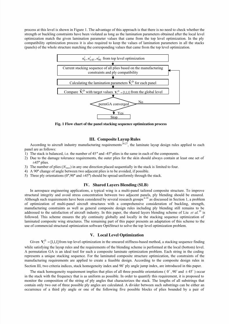
process at this level is shown in Figure 1. The advantage of this approach is that there is no need to check whether the
strength or buckling constraints have been violated as long as the lamination parameters obtained after the local level
optimization match the given lamination parameter values that came from the top level optimization. In the ply
compatibility optimization process it is also required to keep the values of lamination parameters in all the stacks
(panels) of the whole structure matching the corresponding values that came from the top level optimization.
III. Composite Layup Rules
According to aircraft industry manufacturing requirements26,27
1) The stack is balanced, i.e. the number of 45º and -45º plies is the same in each of the components.
, the laminate layup design rules applied to each
panel are as follows:
2) Due to the damage tolerance requirements, the outer plies for the skin should always contain at least one set of
±45º plies.
3) The number of plies ( N max
4) A 90º change of angle between two adjacent plies is to be avoided, if possible.
) in any one direction placed sequentially in the stack is limited to four.
5) Three ply orientations (0º,90º and ±45º) should be spread uniformly through the stack.
IV. Shared Layers Blending (SLB)
In aerospace engineering applications, a typical wing is a multi-panel tailored composite structure. To improve
structural integrity and avoid stress concentration between two adjacent panels, ply blending should be ensured.
Although such requirements have been considered by several research groups6-18
as discussed in Section 1, a problem
of optimization of multi-panel aircraft structures with a comprehensive consideration of buckling, strength,manufacturing constraints as well as general composite design rules including ply blending still remains to be
addressed to the satisfaction of aircraft industry. In this paper, the shared layers blending scheme of Liu et al.19
V. Local Level Optimization
is
followed. This scheme ensures the ply continuity globally and locally in the stacking sequence optimization of
laminated composite wing structures. The remaining part of this paper presents an adaptation of this scheme to the
use of commercial structural optimization software OptiStruct to solve the top level optimization problem.
Given ]1,1,1[= DiV from top level optimization in the smeared stiffness-based method, a stacking sequence finding
while satisfying the layup rules and the requirements of the blending scheme is performed at the local (bottom) level.
A permutation GA is an ideal tool for such a composite laminate optimization problem. Each string in the codingrepresents a unique stacking sequence. For the laminated composite structure optimization, the constraints of the
manufacturing requirements are applied to create a feasible design. According to the composite design rules in
Section III, two criteria indices, stack homogeneity index and
90 ply angle jump index, are introduced in this paper.
The stack homogeneity requirement implies that plies of all three possible orientations ( 0 ,
90 and 45± ) occur
in the stack with the frequency that is as uniform as possible. In order to quantify this requirement, it is proposed to
monitor the composition of the string of ply angles that characterizes the stack. The lengths of all substrings that
contain only two out of three possible ply angles are calculated. A divider between such substrings can be either anoccurrence of a third ply angle or one of the following five possible blocks of plies bounded by a pair of
Fig. 1 Flow chart of the panel stacking sequence optimization process
Compare DiV
~with target values ]1,1,1[= D
iV from the global level
Calculating the lamination parameters DiV
~for each panel
in0 , in 45± , in90 from top level optimization
Current stacking sequence of all plies based on the manufacturing
constraints and ply compatibility
StopYes
No permGA converged

7/27/2019 Optimization of Blended Composite Wing Panels Using Smeared Stiffness Technique and Lamination Parameters
http://slidepdf.com/reader/full/optimization-of-blended-composite-wing-panels-using-smeared-stiffness-technique 7/11
45 and 45− plies: 45/45 − , 45/0/45 − , 45/0/0/45 − , 45/90/45 − and 45/90/90/45 − . Also, in
counting the substring length, occurrences of the same ply angle in two, three, or four sequential plies are counted as
one. Thus, the maximum length of such substrings ( h N ) contributes to the definition of the stack homogeneity index:
h
t N H h2= (7)
where h is the total thickness of the panel,
t is the ply thickness.
The requirement of minimization of the number of occurrences of
90 change in the ply angle for any two
consecutive plies in the stack is quantified by the
90 ply angle jump index:
h
t N A a2= (8)
where a N is the total number of occurrence of
90 ply angle jump in the consecutive plies in the half stack.
In order to combine stack homogeneity index ( H ), 90 ply angle jump index( A ) and lamination parameters
match index ( L ) into a single-objective function, homogeneity index ( H ) and
90 ply angle jump index ( A ) can be
weighted again the lamination parameters match index ( L ) and formulated as:
,
~3
1
2
23
221
∑
−=
++=
=iDi
Di
Di
V
V V L
H W AW LW f
(9)
where f is the objective function,
1W is the weighting coefficient for lamination parameters,
2W is the weighting coefficient for
90 ply angle jump index,
3W is, the weighting coefficient for stack homogeneity index,
DiV is the thi lamination parameter from the top level optimization (that is 1 in our case),
D
iV ~
is the thi computed lamination parameter.
Example
In this example, calculation of stack homogeneity index ( H ) and
90 ply angle jump index ( A ) will be
demonstrated. A symmetric, balanced laminate can be represented as:
[90/0/45/90/-45/90/90/0/0/0/90/0/45/0/-45/90/0/45/90/90/-45/0/90/45/0/0/-45/0/0/90/0/90/45/90/90/-45/0]s .
The total number of occurrence of 90 ply angle jump in the consecutive plies in the half stack ( a N ) of the
above example can be calculated as:h
t N A a2= = =×× 92
h
t =
74
180.243.
The maximum length of such substrings ( h N ) in the above laminate can be represented as:
[90/0/45/90/-45/90/90/0/0/0/90/0/45/0/-45/90/0/45/90/90/-45/0/90/45/0/0/-45/0/0/90/0/90/45/90/90/-45/0]s .
The first length of substrings is 2 because the third angle orientation of block of plies 45/90/45 − follows
immediately after the first ply with 90 angle orientation and the second ply with 0 angle orientation. The second value
of substring length is 4; the third value is 2; the fourth value is 2; the fifth value is 4 and the sixth value is 1. Thus, the
maximum length of such substrings ( h N ) is 4. Thus, the stack homogeneity index 108.074
842 ==××=
h
t H .
2 divider 4 divider 2 divider 2 divider 4 divider 1

7/27/2019 Optimization of Blended Composite Wing Panels Using Smeared Stiffness Technique and Lamination Parameters
http://slidepdf.com/reader/full/optimization-of-blended-composite-wing-panels-using-smeared-stiffness-technique 8/11
VI. Calculation of Lamination Parameters in the Blending Scheme
In the optimization using the lamination parameter-based method, lamination parameters are calculated at the
local level to match the target values from the top level (that all have the value of 1). The lamination parameters are
calculated simultaneously with the blending scheme described in the section IV. Once the first set of shared layers is
determined by the blending scheme, the stacking sequence for the first set of shared layers will be obtained by a
permutation GA to match the lamination parameters from the top level in the thinnest panel. Following that the
values of lamination parameters corresponding to the first set of shared layers in each of the remaining panels arecalculated. Generally, these values will be different in different panels because, following the outer blending scheme,
the distance of the shared layers from the mid-plane varies from panel to panel. Next, the same blending scheme of
determining the second set of shared layers is applied. The stacking sequence of the second set of shared layers will
be determined to match the difference between the lamination parameters from the top level and the values already
calculated for the first set of shared layers in the next thinnest panel (because the first thinnest panel has already beendealt with). This is repeated until the last set of shared layers is considered. Then, lamination parameters contributed
from the sets of shared layers are summed up for each panel. Finally, the stacking sequence of remaining layers in
each panel will be determined to minimize the difference between the lamination parameters from the top level and
the ones summed up in the blending scheme. For detailed information on this procedure see Liu et al.19
VII. Wing Panel Optimization Example
The geometry of a generic aircraft structure in Figure 5 is provided by Altair Engineering. The composite material
for this wing structure is graphite-epoxy: T300/N5208 and its material properties are given in Liu et al.19
. The
detailed root part of the wing structure is shown in Figure 6 and the configuration of the top skin in the root part is
demonstrated in Figure 7.
Figure 5 A generic aircraft structure
The total number of design variables for the skin in the root part is three (t n0 ,
t n 45± , and
t n90 ) per panel. The
weight of all plies for the skin is the objective function. Both buckling and strain constraints are considered inOptiStruct for calculating strains and the buckling load. At the local level, a permutation GA is used to shuffle the
layers to minimize the difference between the values of computed lamination parameters DiV
~for a current stack and
the values ]1,1,1[= DiV from the top level optimization (that is due to the homogeneous property through the thickness
of the laminate). The discrete optimal result for each laminated panel’s design at the top level is shown in the Table 3
and the buckling mode for the discrete design is illustrated in the Figure 8. In the local level optimization, a
permutation GA is used to obtain the stacking sequence for the top skin in the root part as presented in the Table 4.
The computed lamination parameters DiV
~, which are very close to lamination parameters ]1,1,1[= D
iV , are given in the
Table 5 for the discrete optimal design. It can be seen that the values of V 245±
have a greatest difference from the target
values. This is partly due to the limited types of blocks of plies bound by a pair of applied in the permutation
GA. Other block types such as
45/0/45− ,
45/0/0/45− ,
45/90/45− and
45/90/90/45− need to be
developed for better performance of the permutation GA in the stacking sequence optimization. Currently, theweighting coefficients are selected as 5.01 =W , 45.02 =W and 05.03 =W . The selection of the weighting coefficients
longeron
stringers
ribs
Figure 6 Detailed root part with ribs, stringers, and
longerons in the wing structure

7/27/2019 Optimization of Blended Composite Wing Panels Using Smeared Stiffness Technique and Lamination Parameters
http://slidepdf.com/reader/full/optimization-of-blended-composite-wing-panels-using-smeared-stiffness-technique 9/11
for three criteria combined into the single objective function has also effects on the accuracy of the lamination
parameter matching using permGA while satisfying the blending requirement and layup rules. The buckling mode
after the local level optimization for the discrete design is shown in Figure 9. From the comparison of the buckling
load factors from the top level and local level optimization, it can be seen that the value is kept unchanged and the
buckling modes are quite similar for the top and local level optimization results. Once the stacking sequence is
determined that satisfies the blending and manufacturing requirements, no buckling analysis needs to be performed if
the target values of the lamination parameters, passed from the top level, were kept.
Table 3 Discrete optimal results for root part with smeared
stiffness-based method at the top level optimization
Panel Number 0n 45n 90n Total number
(half stack)
Panel 1 12 12 11 47
Panel 2 28 18 20 84
Panel 3 12 59 28 158
Panel 4 14 10 13 47
Panel 5 11 10 21 52
Panel 6 12 14 16 56
Panel 7 24 20 12 76
Panel 8 18 47 28 140
Panel 9 24 40 38 142
Buckling load factor: 1.0055
Figure 7 Top skin configuration
panel
1 panel
2 panel
3
panel
4 panel
5 panel
6
panel
7 panel
8 panel
9
Figure 9 Buckling mode after local level
optimization
Figure 8 First buckling mode for the top skin at
the root part

7/27/2019 Optimization of Blended Composite Wing Panels Using Smeared Stiffness Technique and Lamination Parameters
http://slidepdf.com/reader/full/optimization-of-blended-composite-wing-panels-using-smeared-stiffness-technique 10/11
Panel No. DV 1~
DV 2~
DV 3~
1 1.0092 1.0163 0.9914
2 0.9929 1.0094 1.00613 0.9290 1.0058 0.9226
4 1.0090 1.0161 0.9922
5 0.9912 1.0142 1.0088
6 1.0037 1.0138 1.0062
7 1.0101 1.0108 0.9997
8 0.9809 1.0063 0.9716
9 0.9804 1.0062 0.9713
Stacking sequence
Panel 1[(45/-45)2/03/(45/90/-45)2/45/902/-45/90/03/902/0/45/90/-45/(90/0)2
(45/-45)
/90/
3/03/(45/-45)3]
Panel 2
s
[(45/-45)2/03/(45/90/-45)2/45/902/-45/90/03/902/0/45/90/-45/(90/0)2
(45/-45)
/90/
3/03/45/-45/45/90/-45/(45/-45)2/(45/90/-45)2/45/902/-45/902/(45/0/-
45/ 04)2/90/04/90/02]
Panel 3
s
[(45/-45)2/03/(45/90/-45)2/45/902/-45/90/03/902/0/45/90/-45/(90/0)2
(45/-45)
/90/
3/03/45/-45/45/90/-45/(45/-45)2/(45/90/-45)2/45/902/-45/902/90/
(90/45/902/-45)2/45/902/-45/45/90/-45/(45/-45)39]
Panel 4
s
[(45/-45)2/03/(45/90/-45)2/45/902/-45/90/03/902/0/45/90/-45/(90/0)2(45/-45) /90/
3/03/45/-45/(90/0)2]
Panel 5
s
[(45/-45)2/03/(45/90/-45)2/45/902/-45/90/03/902/0/45/90/-45/(90/0)2
(45/-45)
/90/
3/904/45/0/-45/904/0/902]
Panel 6
s
[(45/-45)2/03/(45/90/-45)2/45/902/-45/90/03/902/0/45/90/-45/(90/0)2
(45/-45)
/90/
3/03/45/-45/45/90/-45/(45/-45)2/45/902/-45/902]
Panel 7
s
[(45/-45)2/03/(45/90/-45)2/45/902/-45/90/03/902/0/45/90/-45/(90/0)2
(45/-45)
/90/
3/03/45/-45/45/90/-45/(45/-45)2/(45/0/-45)5/0/45/02/-45/02/45/02/-
45]
Panel 8
s
[(45/-45)2/03/(45/90/-45)2/45/902/-45/90/03/902/0/45/90/-45/(90/0)2
(45/-45)
/90/
3/03/45/-45/45/90/-45/(45/-45)2/(45/0/-45)5/0/(904/45/902/-45)2/(45/902/-45)2/(45/-45)25]
Panel 9
s
[(45/-45)2/03/(45/90/-45)2/45/902/-45/90/03/902/0/45/90/-45/(90/0)2
(45/-45)
/90/
3/03/45/-45/45/90/-45/(45/-45)2/(45/0/-45)5/0/(904/45/902/-45)2/
(45/902/-45)2/(45/-45)18/03/(0/904)2/0/902]
Buckling load factor: 1.0056
s
VIII. Conclusions
The software implementation of this approach can be considered as an add-on to an OptiStruct run where smeared stiffness-based approach is used for the top level optimization. Given the results from the top level optimization, thestack shuffling to satisfy global blending and manufacturing constraints is performed at the local level to match the
Table 5 Stacking sequence for each panel after the local level optimization
Table 4 Lamination parameters for each panel after the
local level optimization

7/27/2019 Optimization of Blended Composite Wing Panels Using Smeared Stiffness Technique and Lamination Parameters
http://slidepdf.com/reader/full/optimization-of-blended-composite-wing-panels-using-smeared-stiffness-technique 11/11
prescribed values of lamination parameters related to the bending stiffness matrix. This local level optimization can
be treated as a postprocessing phase for determining the detailed ply-book of the laminate while guaranteeing thesatisfaction of strain and buckling constraints.
References1Gurdal, Z., Haftka, R.T., and Hajela, P., Design and Optimization of Laminated Composite Materials, John Wiley & Sons,
1999. 2Schmit, L.A., and Farshi, B., “Optimum Laminate Design for Strength and Stiffness,” International Journal for Numerical
Methods in Engineering, Vol. 7, 1973, pp. 519-536.3Stroud, W.J., and Agranoff, N., “Minimum Mass Design of Filamentary Composite Panels under Combined Loads: Design
Procedure Based on Simplified Equations,” NASA TN D-8257, 1976.4 Nemeth, M.P., “Importance of Anisotropy on Buckling of Compression-Loaded Symmetric Composite Plates,” AIAA Journal
Vol. 24, 1986, pp. 1831-1835.5Kristinsdottir B.P., Zabinsky Z.B., Tuttle M.E., Neogi S., “Optimal Design of Large Composite Panels with Varying Loads,”
Composite Structures, Vol. 51, 93-102, 20016Soremekun, G.A., Gurdal, Z., Kassapoglou, C., and Toni, D., “Stacking Sequence Blending of Multiple Composite Laminates
Using Genetic Algorithm,” Composite Structures, Vol. 56, 2002, pp. 53-62.7
Adams D.B., Watson L.T., Gürdal Z., “Optimization and Blending of Composite Laminates Using Genetic Algorithm with
Migration,” Mechanics of Advanced Material and Structures, Vol 10,183-203,20038Liu, B. and Haftka R.T., “Composite Wing Structural Design Optimization with Continuity Constraint.” Proceedings of 42th
AIAA SDM Conference, AIAA-2001-1205, 2001,Seattle, WA.9Liu, B., Haftka, R.T., and Akgun, M.A., “Two-Level Composite Wing Structural Optimization Using Response Surface,”
Structural and Multidisciplinary Optimization, Vol. 20, 2000, pp. 87-96.10Adams D.B., Watson L.T., Gürdal Z., Anderson-Cook C.M., “Genetic Algorithm Optimization and Blending of composite
Laminates by Locally Reducing Laminate Thickness,” Advances in Engineering Software , Vol 35, pp.35-43, 200411Adams D.B., Watson L.T., Seresta O., Gürdal Z., “Global/Local iteration for Blended Composite Laminate Panel Structure
Optimization Subproblems,” Proceedings of High Performance Computing Symposium, San Diego, CA, 151-157, 200512Seresta, O., Gurdal, Z., Adams, D.B., and Watson, L.T., “Optimal Design of Composite Wing Structures with Blended
Laminates,” Composites Part B: Engineering, Vol. 38, 2007, pp. 469-480.13IJsselmuiden S.T., Seresta O., Abdalla M.M., Gürdal Z., “Multi-step Stacking Sequence Design and Blending of Composite
Structures,” 7th World Congress on Structural and Multidisciplinary Optimization, Seoul, Korea, 21-25 May, 200714IJsselmuiden S.T., Abdalla M.M., Seresta O., Gürdal Z., “Multi-step Blended Stacking Sequence Design of Panel
Assemblies with Buckling Constraints ,” Composite: Part B, Vol, 40, pp. 329-336, 200915van Campen J.M.J.F., Seresta O., Abdalla M.M., Gürdal Z., “General Blending Definitions for Stacking Sequence Design of
Composite Laminate Structures,” 49th AIAA/ASME/ASCE/AHS/ASC Structures, Structural Dynamics, and Material Conference
and 4th AIAA Multidisciplinary Design Optimization Specialist Conference, Schaumburg, IL, 4-7 April, 200816Seresta O., Abdalla M.M., Gürdal Z., “A Genetic Algorithm Based Blending Scheme for Design of Multiple Composite
Laminates,” 50th AIAA/ASME/ASCE/AHS/ASC Structures, Structural Dynamics, and Material Conference and 5th AIAA
Multidisciplinary Design Optimization Specialist Conference, Palm Springs, CA, 4-7 May 2009.17Liu W., butler R., “Optimum Buckling Design of Composite Wing Cover Panels with Manufacturing Constraints,” 48th
AIAA/ASME/ASCE/AHS/ASC Structures, Structural Dynamics & Materials conference, AIAA 2007-2215,Honolulu, Hawaii, 200718Liu, W., and Krog, L., “A Method for Composite Ply Layout Design and Stacking Sequence Optimisation,” Proceedings of
7th ASMO UK/ISSMO Conference, Bath, UK, 2008. 19Liu, D., Toropov, V.V., Querin O.M., and Barton D.C., “Bi-level Optimization of Blended Composite Panels,” 50th
AIAA/ASME/ASCE/AHS/ASC Structures, Structural Dynamics, and Material Conference and 5th AIAA Multidisciplinary Design
Optimization Specialist Conference, Palm Springs, CA, 4-7 May 2009.20Liu, D., Toropov, V.V., Querin O.M., and Barton D.C., “Stacking Sequence Optimization of Composite Panels for Blending
Characteristics Using Lamination Parameters,” 8th World Congress on Structural and Multidisciplinary Optimization, Lisbon,Portugal, 1-5 June 2009.
21Altair OptiStruct Version 9.0, Altair Engineering Inc., 2008.22Jones, R.M., Mechanics of Composite Materials, Second Edition, Taylor and Francis, 1999.23Tsai, S.W., Halpin, J.C., and Pagano, N.J., “Composite Materials Workshop,” Technomic publishing Co., Westport,
Connecticut, 1968, pp. 233-253.24Zhou, M., and Fleury, R., “Optimization of Composite Structures-Understanding and Meeting the Challenges,” Altair
Composite Seminar , Royal Lemington Spa, UK, 2007.25Zhou, M., Fleury R., and Dias W., “Composite Design Optimization-From Concept to Ply-Book Details,” 8th World
Congress on Structural and Multidisciplinary Optimization, Lisbon, Portugal, 1-5 June 2009.26Toropov, V.V., Jones, R., Willment, T., and Funnell, M., “Weight and Manufacturability Optimization of Composite
Aircraft Components Based on A Genetic Algorithm,” Proceedings of 6 th World Congress of SMO, Brazil, 2005.27
Niu, M.C.Y., Composite Airframe Structures, Practical Design Information and Data, Conmilit Press Ltd., Hong Kong.1992.