optimization of drill design and coolant systems …
TRANSCRIPT
University of Kentucky University of Kentucky
UKnowledge UKnowledge
University of Kentucky Master's Theses Graduate School
2004
OPTIMIZATION OF DRILL DESIGN AND COOLANT SYSTEMS OPTIMIZATION OF DRILL DESIGN AND COOLANT SYSTEMS
DURING DENTAL IMPLANT SURGERY DURING DENTAL IMPLANT SURGERY
Varahalaraju Kalidindi University of Kentucky, [email protected]
Right click to open a feedback form in a new tab to let us know how this document benefits you. Right click to open a feedback form in a new tab to let us know how this document benefits you.
Recommended Citation Recommended Citation Kalidindi, Varahalaraju, "OPTIMIZATION OF DRILL DESIGN AND COOLANT SYSTEMS DURING DENTAL IMPLANT SURGERY" (2004). University of Kentucky Master's Theses. 314. https://uknowledge.uky.edu/gradschool_theses/314
This Thesis is brought to you for free and open access by the Graduate School at UKnowledge. It has been accepted for inclusion in University of Kentucky Master's Theses by an authorized administrator of UKnowledge. For more information, please contact [email protected].
ABSTRACT OF THESIS
OPTIMIZATION OF DRILL DESIGN AND COOLANT SYSTEMS DURING DENTAL IMPLANT SURGERY
Dental implants are an effective alternative for the replacement of missing teeth. The success of the implant depends on how well a bone heals around the implant, a process known as osseointegration. However, excessive heat generated during the bone drilling will cause cell death and may prevent osseointegration of the implant, resulting in early failure. There are many factors which contribute to the heat generation during drilling.
Experiments were carried out to investigate the affect of variable drilling factors on heat generation during drilling operation. Natural bone is not an ideal material for such research, as it varies widely in density and other parameters of interest.. It would be desirable to have a more uniform and consistent material to use in such studies. However, such a material must be similar to bone to allow the results to be extrapolated to the clinical situation. The current study describes and validates a model for use in such studies. Polymethylmethacrylate (PMMA) is the material chosen for our studies.
A theoretical model was developed to study the effect of different drilling parameters on temperature rise during drilling operations. Comparison of observed results obtained from experiments was made with the results from theoretical study. Comparison of results for PMMA and human bone are also shown explaining how PMMA material can be substituted for human bone. The results suggest that the PMMA model is an acceptable surrogate for bone in such studies.
Keywords: Dental implants, PMMA, Human bone, Heat generation, Drilling parameters, Coolant system. Varahalaraju Kalidindi
Date: 02/04/04
Copyright © Varahalaraju Kalidindi 2004
OPTIMIZATION OF DRILL DESIGN AND COOLANT SYSTEMS DURING DENTAL IMPLANT SURGERY
By
Varahalaraju Kalidindi
Dr. Kozo Saito (Director of Thesis) Dr. George Huang (Director of Graduate Studies)
Date: 02/04/2004
RULES FOR THE USE OF THESIS Unpublished thesis submitted for the Master’s degree and deposited in the University of Kentucky Library are as a rule open for inspection, but are to be used only with due regard to the rights of the authors. Bibliographical references may be noted, but quotations or summaries of parts may be published only with the permission of the author, and with the usual scholarly acknowledgements. Extensive copying or publication of the thesis in whole or in part also requires the consent of the Dean of the Graduate School of the University of Kentucky.

THESIS
Varahalaraju Kalidindi
The Graduate School
University of Kentucky
2004
OPTIMIZATION OF DRILL DESIGN AND COOLANT SYSTEMS
DURING DENTAL IMPLANT SURGERY
________________________________
THESIS ________________________________
A thesis submitted in partial fulfillment of the requirements
for the degree of Master of Science in the College of Engineering at the
University of Kentucky
By
Varahalaraju Kalidindi
Lexington, Kentucky
Director: Dr. Kozo Saito,
(Professor of Mechanical Engineering)
Lexington, Kentucky
2004
Copyright © Varahalaraju Kalidindi 2004

TO MY FAMILY AND FRIENDS.
iii
ACKNOWLEDGMENTS
The following thesis, while an individual work, benefited from the insights and direction
of several people. I would like to thank my Thesis Chair, Dr. Kozo Saito, for providing an
excellent opportunity to work under his able guidance. In addition Dr. Mohammed I. Hassan and
Dr. Abraham Salazar provided timely and instructive comments and evaluation at every stage of
the thesis process, allowing me to complete this project on schedule. Next, I wish to thank the
Thesis Committee: Dr. I.S. Jawahir and Dr. Mark V. Thomas. Each individual provided insights
that guided and challenged my thinking, substantially improving the finished product. This study
was supported, in part, by an R&D Excellence Grant from the Kentucky Science and Technology
Council (KSEF 148-502-02-30; PI: M.. Thomas; Co-I: K. Saito and I. Jawahir).
In addition to the technical and instrumental assistance above, I received equally
important assistance from my family and friends. Finally, I would like to thank my friends from
the University of Kentucky College of Dentistry (Division of Periodontology), Drs. Aaron
Carner, Neil Lemmerman, and the IAES group, with whom I've shared and discussed this project
in several versions. I would also like to thank Richard and other people from Center for
manufacturing in University of Kentucky for helping me to carry out experiments. Their help,
advice, and support have been vital throughout.
iv
TABLE OF CONTENTS
ACKNOWLEDGMENTS ............................................................................................................. iii
LIST OF TABLES........................................................................................................................ vii
LIST OF FIGURES ..................................................................................................................... viii
LIST OF FILES ............................................................................................................................. ix
CHAPTER 1:INTRODUCTION.................................................................................................... 1
1.1 BACKGROUND .................................................................................................................. 1
1.2 DENTAL IMPLANT SURGERY ........................................................................................ 2
1.2.1 Surgical Placement......................................................................................................... 3
1.2.2 Uncovering the implant.................................................................................................. 4
1.3 DENTAL IMPLANT FAILURES........................................................................................ 4
1.4 OBJECTIVES....................................................................................................................... 6
1.5 METHODOLOGY ............................................................................................................... 6
1.6 THESIS OVERVIEW........................................................................................................... 6
CHAPTER 2:LITERATURE SURVEY......................................................................................... 8
2.1 BACKGROUND .................................................................................................................. 8
2.2 FACTORS AFFECTING HEAT GENERATION ............................................................... 8
2.2.1 Drilling Speed ................................................................................................................ 9
2.2.2 Drilling Status ................................................................................................................ 9
2.2.3 Drilling Depth .............................................................................................................. 10
2.2.4 Drill Design and Flute Geometry................................................................................. 10
2.2.5 Irrigation Systems ........................................................................................................ 10
2.2.6 Drill Sharpness............................................................................................................. 11
2.2.7 Miscellaneous Factors.................................................................................................. 11
CHAPTER 3:MATERIALS & METHODS................................................................................. 13
v
3.1 PMMA ................................................................................................................................ 13
3.1.1 General Properties........................................................................................................ 14
3.1.2 Comparison of thermal properties for Human bone and PMMA ................................ 14
3.2 METHOD ........................................................................................................................... 15
3.2.1 Positioning of thermocouples ...................................................................................... 15
3.2.2 Experimental Setup...................................................................................................... 16
3.2.3 Experimental Conditions ............................................................................................. 18
3.2.4 Data Analysis ............................................................................................................... 19
CHAPTER 4:THEORETICAL EQUATION............................................................................... 21
4.1 MODELING APPROACH................................................................................................. 21
4.1.1 Thermal Analysis ......................................................................................................... 21
4.1.2 Thermograph Image..................................................................................................... 22
4.1.3 Assumptions................................................................................................................. 22
4.2 DERIVATION.................................................................................................................... 23
4.3 EXPRESSION FOR HEAT FLUX .................................................................................... 28
CHAPTER 5:RESULTS & DISCUSSION .................................................................................. 33
5.1 EXPERIMENTAL RESULTS............................................................................................ 33
5.1.1 Drill speed.................................................................................................................... 33
5.1.2 Drilling depth ............................................................................................................... 34
5.1.3 Drill diameter ............................................................................................................... 35
5.1.4 External Coolant .......................................................................................................... 36
5.1.5 Drill feed rate ............................................................................................................... 37
5.1.6 Single step or Incremental drilling............................................................................... 38
5.2 MODEL VALIDATION .................................................................................................... 40
5.2.1 Comparison for PMMA and human bone.................................................................... 40
5.2.2 Comparison of experimental &theoretical results for pmma....................................... 41
5.2.3 Comparison for drilling parameters ............................................................................. 42
CHAPTER 6: SUMMARY AND CONCLUSIONS.................................................................... 45

vi
6.1 SUMMARY........................................................................................................................ 45
6.2 CONCLUSIONS................................................................................................................. 46
6.3 FUTURE WORK................................................................................................................ 47
APPENDIX 1................................................................................................................................ 48
REFERENCES ............................................................................................................................. 48
VITA............................................................................................................................................. 53

vii
LIST OF TABLES Table 3.1: Comparison of properties for Bone and PMMA……………………………………..14 Table 3.2: Table of drilling parameters…………………………………………………………..19 Table 5.1 Values substituted for PMMA and Bone……………………………………………...40
viii
LIST OF FIGURES Figure 1.1: Schematic of Dental Implant...................................................................................... ..2
Figure 1.2: Implants placed inside Bone ........................................................................................ 3
Figure 1.3: Root Form Implant ....................................................................................................... 4
Figure 2.1:Structure of PMMA..................................................................................................... 13
Figure 3.1: Heat generation recorded using infrared camera........................................................ 15
Figure 3.2: Schematic of the experimental setup.......................................................................... 17
Figure 3.3: Experimental Setup .................................................................................................... 17
Figure 3.5 Thermocouple readings using 2 mm drill at 1200 rpm and 16 mm depth .................. 19
Figure 4.1: Thermal analysis on PMMA using ANSYS software................................................ 21
Figure 4.2: Heat generation recorded using infrared camera........................................................ 22
Figure 5.1:Temperatures at drilling speed of 1200,1800 and 2200 RPM..................................... 34
Figure 5.2: Temperatures measured at drilling depths of 8,12,16 mm......................................... 35
Figure 5.3: Temperatures measured with drills of 2,3.5and 4.3 mm diameter............................. 36
Figure 5.4:Temperatures measured when drilling with/without external coolant ........................ 37
Figure 5.5: Temperatures measured at different feed rates .......................................................... 38
Figure 5.6: Temperatures when drilled continuously & gradually for 3.5 and 4.3 mm holes...... 39
Figure 5.7 Comparison of Results for PMMA and Human bone ................................................. 41
Figure 5.8: Comparison of Results from model and experiments for PMMA ............................. 41
Figure 5.9: Comparisons for Drilling Depth................................................................................. 42
Figure 5.10: Comparison of results for Feed rates........................................................................ 43
Figure 5.11: Comparison of results for drill diameter .................................................................. 43

ix
LIST OF FILES Kalidindi.pdf………………………………………………………………………………702 KB
1
CHAPTER 1
INTRODUCTION
1.1 BACKGROUND Despite significant progress in treatment and prevention of dental disease, many teeth are
lost due to disease and trauma. Life’s simple pleasures can cause problems and pain for millions
of people who suffer from permanent tooth loss. Men and women of all ages are self conscious
about their dentures, bridges or missing tooth. Some have difficulty speaking because their
dentures slip or click. For others, the irritation and pain caused by dentures are constant
reminders of the limitations they feel. Many are concerned about their appearance and may feel
that their tooth loss has “aged them” before their time. Some regularly decline invitations to
social events because they are unwilling to face the uncertainties of eating, speaking and
laughing in public.
A number of options exist for the replacement of missing teeth. The most recent of these
is dental implant. Modern dental implants are the treatment of choice for the replacement of
missing teeth. Dental implants offer an excellent alternative to the limitations of conventional
dentures, bridges and missing teeth. Dental implants are changing the way people live, they are
rediscovering the comfort and confidence to eat, speak, laugh and enjoy life.
National surveys have documented the increased interest in dental implants on the part of
patients and the dental profession. One recent survey reported that [3]:
• Dental implant use has nearly tripled since 1986 and is expected to continue to rise
rapidly.
• People of all ages are turning to dental implants to replace a single tooth, several teeth or
a full set of dentures.
• Leading reasons cited for choosing dental implants are:
To restore normal eating and speaking abilities.
To enhance facial appearance and confidence.
To increase denture retention.
2
According to the survey, the reasons for the increased demand are:
Growing public awareness of the significant functional and esthetic advantages of dental
implants over conventional dentures and bridges.
The availability of data on the long-term success of dental implants.
Dental implants are a great option for patients missing natural teeth, because they act as a
secure anchor for artificial replacement teeth and eliminate the instability associated with surface
adhesives and removable bridges. Natural teeth absorb biting pressure of up to 540 Psi [3]. Long-
time denture-wearers can often absorb no more than 50 Psi. Dental implants, when properly
placed, can withstand 450 Psi of biting pressure. Dental implants are made of materials that are
compatible with human bone and tissue.
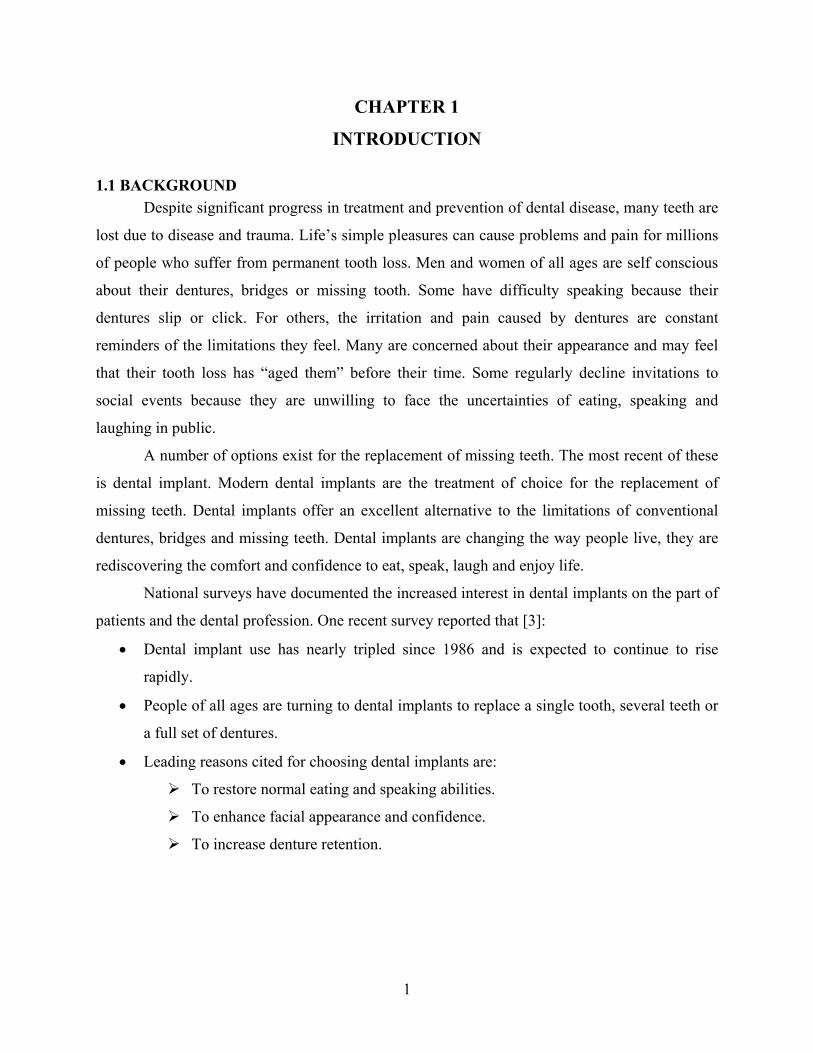
1.2 DENTAL IMPLANT SURGERY
Dental implant surgery, where the dentist implants a metallic tooth-root in the bone of
human jaw and allows the bone to heal on it for a reasonable period of time until the bone and
the metallic root union is strong enough to support a prosthetic tooth crown. The implant root is
made out of titanium, a metal that is very well tolerated by the human body.
Figure 1.1: Schematic of Dental Implant
3
Dental implant surgery takes place in two stages:
1) Surgical placement and
2) Uncovering the implant.
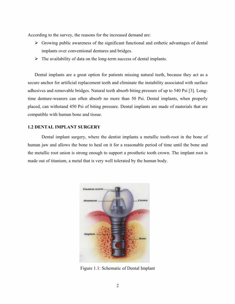
1.2.1 Surgical Placement A hole is being drilled into the bone where the implant is supposed to be placed. An
implant is screwed or tapped into the surgically prepared site. The gum tissue is closed over the
implant. After this stage has been completed, an average time between 3 to 6 months is given to
allow the bone to heal around implant. The suitable time depends upon the bone of the patient.
For the first three to six months following surgery, the implants are beneath the surface of the
gums, gradually bonding with the jawbone. During this time, the patient should be wearing
temporary dentures and eat a soft diet. While the implants are bonding with the jawbone, new
replacement teeth are fashioned by dentist. The replacement teeth must clip onto the implants, fit
securely in the mouth and withstand the day-to-day movement and pressure created by chewing
and speaking.
Figure 1.2: Implants placed inside Bone
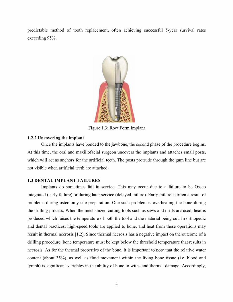
Most currently used dental implants consist of a root-shaped portion that is anchored to
the bone. Various types of dental restorations (e.g., single crowns, bridges, and even complete
over dentures) can be attached to the root-form implant. The surgical placement of the implant
involves preparing a hole in the jaw that corresponds in size and shape to the implant. This is
known as the osteotomy site. The implant is then threaded into the hole (in a manner somewhat
similar to wood screw) or is a tight press-fit. Over a period of time, bone becomes deposited on
the implant surface, a phenomenon known as Osseo integration. While the nature of this
interface has not been fully elucidated, it is robust. Many studies have shown implants to be a
4
predictable method of tooth replacement, often achieving successful 5-year survival rates
exceeding 95%.
Figure 1.3: Root Form Implant
1.2.2 Uncovering the implant Once the implants have bonded to the jawbone, the second phase of the procedure begins.
At this time, the oral and maxillofacial surgeon uncovers the implants and attaches small posts,
which will act as anchors for the artificial teeth. The posts protrude through the gum line but are
not visible when artificial teeth are attached.
1.3 DENTAL IMPLANT FAILURES Implants do sometimes fail in service. This may occur due to a failure to be Osseo
integrated (early failure) or during later service (delayed failure). Early failure is often a result of
problems during osteotomy site preparation. One such problem is overheating the bone during
the drilling process. When the mechanized cutting tools such as saws and drills are used, heat is
produced which raises the temperature of both the tool and the material being cut. In orthopedic
and dental practices, high-speed tools are applied to bone, and heat from these operations may
result in thermal necrosis [1,2]. Since thermal necrosis has a negative impact on the outcome of a
drilling procedure, bone temperature must be kept below the threshold temperature that results in
necrosis. As for the thermal properties of the bone, it is important to note that the relative water
content (about 35%), as well as fluid movement within the living bone tissue (i.e. blood and
lymph) is significant variables in the ability of bone to withstand thermal damage. Accordingly,
5
in thermal conductivity studies using living oxen bone tissue, Vacheon et al 1967 [4]. For dry
versus living oxen bone, the values reported for thermal conductivity were 1.45 * 10-3 and 5.45 *
10-3 cal/cm-sec respectively. Bone is a poor conductor of heat, with thermal conductivity of fresh
cortical bone in the region of 0.38-2.3 J/msK. It has been documented that bone cell death may
occur when bone is heated over 47 0C [1,5]. In the absence of irrigation, bone temperatures may
exceed 100 0C. This may result in a failure of bone to bond to the implant, leading to early
failure.
Implant therapy involves some expense and inconvenience to the patient. It is important
to improve outcomes and minimizing treatment failures. Given the deleterious effect of heat on
bone viability, one strategy for optimizing implant outcomes may be reduction of heat during
osteotomy site instrumentation. This strategy is likely to find application in other disciplines such
as orthopedic and plastic surgery.
Various strategies have been employed to reduce heat generation during implant site
preparation, including variations in drill design and coolant delivery. There are many factors that
contribute to heat generation during the drilling operation. However, there is lack of unanimity
regarding the optimal combination of drill design features and coolant delivery and there is
relatively little in the implant literature on these topics. The factors can be listed as :
1) Drilling speed
2) Drill feed
3) Drilling status (continuous or graduated drilling)
4) Drilling depth
5) Drill design
6) Irrigation (coolant delivery) systems
7) Drill Sharpness
8) Miscellaneous Factors.
To check how these factors affect heat generation we carry out a series of experiments
under different conditions. This needs large number of human bone samples, which is a big
problem in obtaining. So we looked for an alternative material that can be easily available which
is similar to that of a bone in properties and functioning. The material we are considering here is
polymethylMethacrylate (PMMA).
6
1.4 OBJECTIVES The Primary objective of this research study is to reduce the amount of heat generated
during the Osseo integration process and create a thermal model that can explain how the
temperature increases during drilling process.
The main objectives of this thesis can be listed as follows:
1) Study the effect of different drilling operation parameters on temperature rise during
drilling process on PMMA (as replacement to human bone) by conducting series of
experiments.
2) Create a thermal model that can describe the temperature increase as function of variable
drilling parameters.
3) Validate the thermal model by comparing its results with the experimental results and
explain how it can be interpolated for human bone.
4) To come out with optimal drilling conditions that can help dental surgeons in reducing
dental implant failures.
1.5 METHODOLOGY
To obtain the objectives listed this study is being carried out in three stages:
1. Formulating a theoretical model that can help in explaining the temperature rise during
drilling process.
2. Carry out series of experiments varying different drilling parameters and check how these
factors are going to affect temperature rise. These experiments are performed on PMMA
3. Compare the experimental results with theoretical results to validate the thermal model
developed for this case.
1.6 THESIS OVERVIEW Chapter 2 gives the detailed back ground on reasons for dental implant failures. It also
explains how previous researchers differed in their findings about the affect of variable drilling
conditions on temperature increase during the drilling process for placing implants. Chapter 3
explains about the materials and method used for carrying out experiments. It explains in detail
why polymethylmethacrylate(PMMA) being considered instead of human bone for experiments.
It also includes detailed description of the experimental setup used for experiments and explains t
why this setup is being used. Chapter 4 explains modeling approach used for deriving the

7
thermal model to predict temperature rise as a function of drilling parameters. It also includes in
detail the derivation for that equation and nomenclature used. Results obtained during
experimental study are discussed in chapter 5. Comparisons of results obtained from thermal
model and experiments are compared in this chapter. Chapter 6 summarizes the whole study and
results obtained and also explain about how the future work can be done in this field.
Copyright © Varahalaraju Kalidindi 2004
8
CHAPTER 2
LITERATURE SURVEY
2.1 BACKGROUND
Dental implant surgery process involves drilling a hole inside the bone. This drilling
operation causes heat generation due to the friction between the drill and bone. Majority of heat
generated during this process is absorbed by drill but bone also absorbs significant amount of
heat inside it. Heat absorbed by human bone causes the temperature to rise inside it.
The negative affect of heat on bone results in the denaturation of the enzymatic and
membrane proteins, hyperemia, necrosis, fibrosis, decreased osteoclastic and osteoblastic
activity, dehydration, and desiccation, which may all contribute to cell death [5, 6, 7, 8, 9 ].
Historically, temperatures anywhere from 56oC to 70oC have been deemed responsible for the
denaturation [10,11]. However, in a landmark study by Eriksson and Albrektsson [12,13,14], it
was determined that the critical temperature of bone is in the range of 44oC to 47oC. They found
that the threshold temperature for heat induced bone injury is 47oC for 1 minute. A temperature
of more than 47oC was shown to result in bone restoration and fat-cell degeneration. Heating the
bone to temperatures lower than 47oC did not seem to affect the bone tissue on the microscopic
level, but vascular injury, as seen with increased capillary injury, was seen by others to occur at
lower temperatures [15]. As a result of Eriksson and Albrektsson’s study, the critical temperature
is widely believed to be 47 oC. However, it must be observed that this experiment did not involve
drilling of the bone but merely heating the saline solution to a desired temperature, which was in
direct contact to the bone.
2.2 FACTORS AFFECTING HEAT GENERATION
There are many factors that affect the heat generation during the drilling process. After a
detailed literature survey, the factors that can affect temperature raise during drilling process can
be listed as follows:
1) Drilling Speed
2) Drilling Status (single step or incremental drilling)
3) Drilling Depth
4) Drill Diameter
9
5) Irrigation (coolant delivery) systems
6) Drill Sharpness
7) Miscellaneous factors.
In this section we describe how different factors affect the heat generation during bone
drilling. The details given below are collected from the results obtained by different researchers,
which are been collected as part of the literature survey that has been done regarding the project.
2.2.1 Drilling Speed There are many varying results from different researchers about the optimal speed for
dental implant surgery. Thompson and Pallan,[17,18] measured in vivo the temperature rise in
bone increased with drill speed, from 125 rpm to 2000 rpm. Eriksson has shown that using high
torque and low rpm (1500-2000) are ideal to avoid temperature rise and to increase drilling
accuracy. Matthews and Hirsch, [16] however did not find any significant change in temperature
rise with speed (350 to 2900 rpm) while drilling in human cadaveric femora. Vaughn and Peyton
found that the temperature rise increased with drill speed (from 1155 rpm to 11,300 rpm). In the
more recent studies, Abouzgia and James [19] found that the maximum temperature rise
decreased with speed, for free running speeds from 27,000 rpm to 97,000 rpm. Except for the
study by Matthews and Hirsch [16], there seems to be general agreement that the temperature
rise increases with drill speed up to approximately 10,000 rpm. Results from the majority of
histological studies and from the temperature measurements from Abouzgia and James [19]
appear to indicate that lower temperatures are generated at very high drill speeds.
2.2.2 Drilling Status Drilling to widen the site to exact diameter of the future implant can be performed either
one step or gradually. In continuous or one step drilling the hole is being drilled in a single step
using a single drilling tool. In incremental or multi-step drilling the diameter is increased
gradually starting from the minimum to the final diameter using a series of drilling tools.
Eriksson [20] has described a single step technique while Branemark [21] has
recommended an incremental enlargement of the osteotomy site. Branemark’s[21] hypothesis on
the incremental drilling sequence was that each drill bit gradually enlarges the osteotomy site,
which would help dissipate heat better than a one-stage drill sequence. In a later study, Eriksson
did an in vivo study in which animals and humans are subjected to either incremental or one-
10
stage osteotomy preparation. In this study, Eriksson found that the incremental drilling is better
on reducing heat production compared to single drilling.
2.2.3 Drilling Depth Depth of the recipient site is usually determined by several factors. Cordioli and Majzoub
[22] reported a significant increase in temperature at depths of 8 mm versus 4 mm, regardless of
the diameter of the drill used. However, Tehemar [23] believes that the implant depth may not be
as important as having irrigation at the apical extent of the drill that would thus decrease heat
production.
2.2.4 Drill Design and Flute Geometry Root-form implants vary considerably in design for biologic and mechanical reasons.
Because the end result of the drilling cascade has to be a recipient bony bed of the same diameter
and shape of the proposed implant, the drills usually follow the morphologic and topographic
skeleton of the implant. With the great variety of dental systems commercially available,
comparison between the different designs and shapes of drills seems to be impossible.
In general, twist drills and taps are used to prepare sites for screw-shaped implants, and
triflute drills are used to prepare sites for cylindrical implants. Investigations performed on
animals and human bone have demonstrated that flute geometry and drill design contribute to the
temperature rise during drilling. Cordioli and Majzoub [22] compared the different types of drills
on heat generated in bovine bone blocks. They reported that a triflute drill 4 mm in diameter
generated less heat than 2 and 3 mm twist drills and a 3.3 mm triflute drill regardless of the
cavity depth. They also found out that temperature took longer to return to baseline using a
smaller diameter drill versus a large diameter drill. However Tehemar [23] believes the opposite.
He believes that the wider diameter burs take less bone than the smaller diameter drills which
results in wider diameter drills producing less heat.
2.2.5 Irrigation Systems In an effort to increase heat dissipation during dental implant drilling and thus, decrease
bone temperature, implant systems have began to use irrigation systems with coolants. There are
two types of cooling: internal and external. If one does not use any coolant, then the critical bone
temperature is always exceeded. Kirschner and Meyer [24] introduced internally cooled drills to
dentistry. They hypothesized that since the coolant entered closer to the tip of the drill, it would
11
create a combined rinsing and cooling effect on the bone, which would surpass the externally
cooled drill or a drill with no coolant at all. Huhule [25] was the first to propose the internal
irrigation system which he believed would help prevent bone “clogging” of the implant drill and
that its efficacy would be continuous because all depths of the osteotomy preparation could be
reached with the coolant.
Despite the promising results reported using internal irrigation systems, this issue
requires further study. The only report present in the literature is that of Haider [26] et al. In their
histological and histochemical study, this group demonstrated that additional external cooling
seemed to be beneficial for any internal system, particularly in compact bone. Thus, it appears
that irrigation is a key implant in implant osteotomy preparation and is worthy of more
investigation.
2.2.6 Drill Sharpness The condition of drill plays a role in regulating the temperature of bone during drilling.
There are many factors that reduce the sharpness of a drill, density of bone, use of the drill, the
debris released during the process, material construction & surface treatment of drill. A worn
drill will thus have more heat production than a sharper drill. Previous analysis using scanning
electron microscopy revealed tangible wear on the cutting edges of trephine drills after 12 to 18
milling procedures. Although the number of sites to be prepared before drill change is usually
suggested by some manufacturers, visual examination or the observation of when the drill fails to
progress rapidly, frequently indicate the need for a new drill.
2.2.7 Miscellaneous Factors The temperature produced also depends on many factors like drilling time, age of the
patient, density of the bone, texture of the bone etc. it has been well documented that older
patients, certain physiological changes occur. Bony structures tend to become denser and more
fragile, the medullary cavity space enlarges faster resulting in a net decrease of cortical thickness
and mass, and healing capability is usually impaired. Although some features of bone have been
evaluated in terms of heat, the effect of heat in relation to age has not been studied.
Bone usually varies in density from person to person, bone to bone in the skeleton, and
from site to site in the same bone. Regarding the effect of density on the temperature generated,
12
Yacker and Klein[29] reported that bone density is a far greater indicator of bur temperature than
depth of the osteotomy. However, further studies are necessary to resolve this issue.
Time can be considered as the time of drilling, or the time required for the heated part to
return to its normal temperature. The time taken for drilling is directly proportional to the amount
of heat generated during drilling. Results show that heating bone at 47°C for 5 minutes results in
20% resumption of original over 30 days. The ideal fastest time for drilling from the previous
results was obtained as 2400 rpm with 2.4 kg of pressure to drill 7 mm hole with least
temperature rise.
During the literature survey we find that there has been divergence in the opinion
between the different researchers regarding how different factors affect the heat generation.
More over majority of the observations which are listed above are being observed from an in
vitro study. But the in vivo situation is different compared to that from in vitro due to the effects
of ambient body temperature, heat transfer via bodily fluids, etc in order to obtain accurate
results we need to include all the factors and the observations must be done in real time.
Copyright © Varahalaraju Kalidindi 2004
13
CHAPTER 3
MATERIALS & METHODS
To check how different factors as listed in previous chapter affect heat generation, series
of experiments are planned under variable drilling conditions. This needs large number of
consistent human bone samples. Since human bone differ in its density and shape depending
upon gender, age and other factors, it is extremely difficult to obtain consistent quality human
bone samples. This resulted in looking for an alternative material that can be easily available
with consistent quality and similar to that of a human bone in properties and functioning. The
material that is being considered here is poly methyl Methacrylate (PMMA).
3.1 PMMA Polymethylmethacrylate or acrylic bone cement is the most commonly used non-metallic
implant material in orthopedics. PMMA is one of the earliest polymers and is well known around
the world by a variety of trade names Lucite, Oroglas, Perspex and Plexiglas, which vary with
the country you are in. PMMA (Polymethyl methacrylate) was first discovered in Germany in
1902 by the chemist O. Röhm and was patented in 1928. The first medical use of PMMA was in
1936 as dental prostheses.
The original PMMA was seen as a replacement for glass in a variety of applications and
is currently used extensively in glazing applications. The material is one of the hardest polymers,
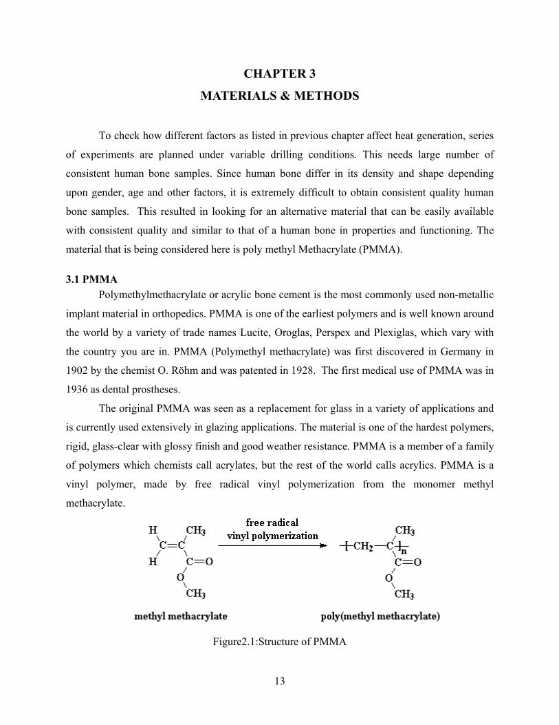
rigid, glass-clear with glossy finish and good weather resistance. PMMA is a member of a family
of polymers which chemists call acrylates, but the rest of the world calls acrylics. PMMA is a
vinyl polymer, made by free radical vinyl polymerization from the monomer methyl
methacrylate.
Figure2.1:Structure of PMMA
14
PMMA has become essential ingredient in making dentures. In mid 1950s charnley [31]
first introduced a self-curing PMMA to orthopedic surgery. He successfully fixed both the
femoral and actebular components in a total hip replacement using PMMA, and with more
pioneering efforts, Charnley and his group, revolutionized reconstructive surgery of the hip and
other joints as well. Today most total joint replacement surgery, including hip, knee, and ankle,
use acrylic bone cement as fixation of the prosthesis to the bone. Bone cement is also often used
in the fixation of pathological features, and it has also been utilized in the repair of bone defects.
Acrylic bone cement is still utilized as dental cement due to its low water absorption, non-
toxicity, dimensional stability, and ease of forming.
3.1.1 General Properties PMMA is a glassy polymer with an amorphous structure. It has a density of 1.19 g/cm3
and has very low water absorption. The refractive index ranges from 1.49 to 1.51 depending on
the type. Parts made of PMMA have high mechanical strength and good dimensional stability.
Other properties include a high Young's modulus and good hardness with low elongation at
break. PMMA does not shatter on rupture. PMMA is one of the hardest thermoplastics and is
also highly scratch resistant.
3.1.2 Comparison of thermal properties for Human bone and PMMA PMMA has similar thermal properties compared to the human bone. Properties of both the bone
and PMMA can be seen in the following table [32]:
Table 3.1: Comparison of properties for Bone and PMMA
Properties Bone PMMA
Thermal conductivity (W/m K) 0.15-0.35 0.15-0.4
Specific heat (J/Kg K) 1300 1400
Thermal diffusivity (m2/sec) 0.3*10-6 0.11*10-6
Density (Kg/m3) 1800 1400
15
3.2 METHOD To check the effect of variable drilling factors on the temperature rise during drilling
operations series of experiments are planned. Experiments are being carried out on Drilling
machine (HAAS VFOE 20HP) in CMS (Center for Manufacturing Systems) machine shop at the
University of Kentucky. PMMA specimens of 5cm diameter and 2cm thickness are prepared to
perform the experiments.
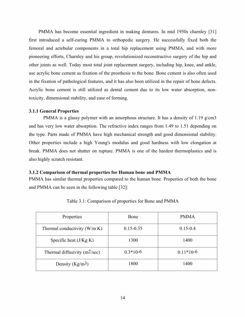
3.2.1 Positioning of thermocouples The thermocouples locations are chosen based on the images obtained from infrared
thermograph camera during drilling operation. Images from the infrared thermograph helped in
determining the isothermal lines distribution around the drilled hole, as shown in the figure 3.1.
Figure 3.1: Heat generation recorded using infrared camera
The isothermal lines showed that heat is radially conducted from the drilled hole. The
images are taken by FLIR IR camera, which has a wavelength dector of 7.5-13 mµ . From the
table temperatures recorded at different positions during drilling process can be observed.
Maximum temperature obtained during the drilling process is of main concern. Tip of the
16
thermocouples should be placed where it can record accurately the maximum temperature
absorbed by the specimen during the drilling process and should be careful that thermocouples
does not touch the drill during the drilling operation. Higher temperatures recorded at SPO1 and
SP02 positions corresponds to the temperature absorbed by the drill. SPO3 is the position where
the thermocouples can be placed to record maximum temperatures obtained to the drilling
process without any damage to it.
Locations for placing thermocouples are calculated using Adobe Photoshop software. To
record the maximum temperatures that are produced during drilling, Thermocouple 1 should be
placed at a distance of 6 mm from the top and 6 mm away from the center and Thermocouple 2
is to be placed 6 mm below the first one but at the same distance from the center.
3.2.2 Experimental Setup Experimental setup for carrying out these experiments include two type K thermocouples
for recording temperatures, Data acquisition equipment for retrieving data from thermocouples,
drilling machine and a PMMA specimen. Two holes are drilled into the PMMA specimen for
placing thermocouples. These holes are drilled in such a way that thermocouples can be inserted
easily into the specimen and can reach the exact positions they are supposed to be. These holes
are being drilled using 0.9 mm diameter drills. Type K thermocouples (Omega) are used for
recording the temperature rise during the drilling operation. These thermocouples are connected
to data acquisition equipment (Data Acquisition System: IO Tech DaqBook/260, 14 channels).
This data acquisition system acquires temperature data during the drilling process by the rate of
10 temperatures–samples/second.
Data acquisition system is directly connected to a laptop, which transfers the data directly
to Microsoft Excel sheet. Data recording from thermocouples will be started and stopped by
manual trigger. For a specific drilling condition, experiments are carried out on three specimens.
Average value of the maximum temperatures obtained for three identical specimens under the
same identical conditions will be taken and that value will be recorded as the temperature
obtained for that specific drilling condition. Experiments will be repeated for variable drilling
conditions.
17
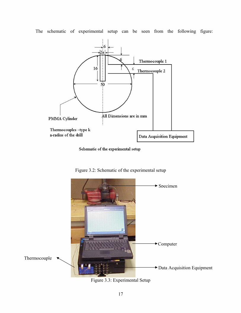
The schematic of experimental setup can be seen from the following figure:
Figure 3.2: Schematic of the experimental setup
Figure 3.3: Experimental Setup
Specimen
Data Acquisition Equipment
Computer
Thermocouple
18
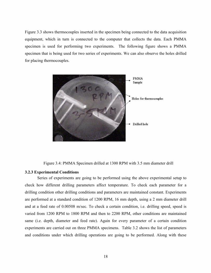
Figure 3.3 shows thermocouples inserted in the specimen being connected to the data acquisition
equipment, which in turn is connected to the computer that collects the data. Each PMMA
specimen is used for performing two experiments. The following figure shows a PMMA
specimen that is being used for two series of experiments. We can also observe the holes drilled
for placing thermocouples.
Figure 3.4: PMMA Specimen drilled at 1300 RPM with 3.5 mm diameter drill
3.2.3 Experimental Conditions Series of experiments are going to be performed using the above experimental setup to
check how different drilling parameters affect temperature. To check each parameter for a
drilling condition other drilling conditions and parameters are maintained constant. Experiments
are performed at a standard condition of 1200 RPM, 16 mm depth, using a 2 mm diameter drill
and at a feed rate of 0.00508 m/sec. To check a certain condition, i.e. drilling speed, speed is
varied from 1200 RPM to 1800 RPM and then to 2200 RPM, other conditions are maintained
same (i.e. depth, diameter and feed rate). Again for every parameter of a certain condition
experiments are carried out on three PMMA specimens. Table 3.2 shows the list of parameters
and conditions under which drilling operations are going to be performed. Along with these
19
parameters, experiments are also carried out to check how external coolant and incremental
drilling procedures affect the temperature change during drilling operations.
Table 3.2: Table of drilling parameters
CONDITIONS PARAMETERS
Drilling Speed (R.P.M) 1200, 1800, 2200
Drilling Depth (mm) 8, 12, 16
Drill Bit Diameter (mm) 2.00, 3.50, 4.30
Drill Feed Rate (m/sec) 0.00508, 0.01016,0.01524
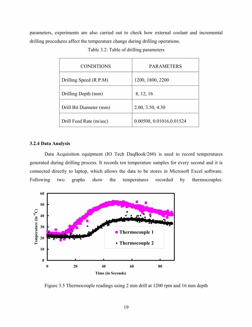
3.2.4 Data Analysis
Data Acquisition equipment (IO Tech DaqBook/260) is used to record temperatures
generated during drilling process. It records ten temperature samples for every second and it is
connected directly to laptop, which allows the data to be stores in Microsoft Excel software.
Following two graphs show the temperatures recorded by thermocouples:
0
10
20
30
40
50
60
0 20 40 60 80
Time (in Seconds)
Tem
pera
ture
(in
OC
)
Thermocouple 1
Thermocouple 2
Figure 3.5 Thermocouple readings using 2 mm drill at 1200 rpm and 16 mm depth
20
0
10
20
30
40
50
60
0 10 20 30 40 50 60 70 80
Time (in Seconds)
Tem
pera
ture
(in
OC
)
Thermocouple 1
Thermocouple 2
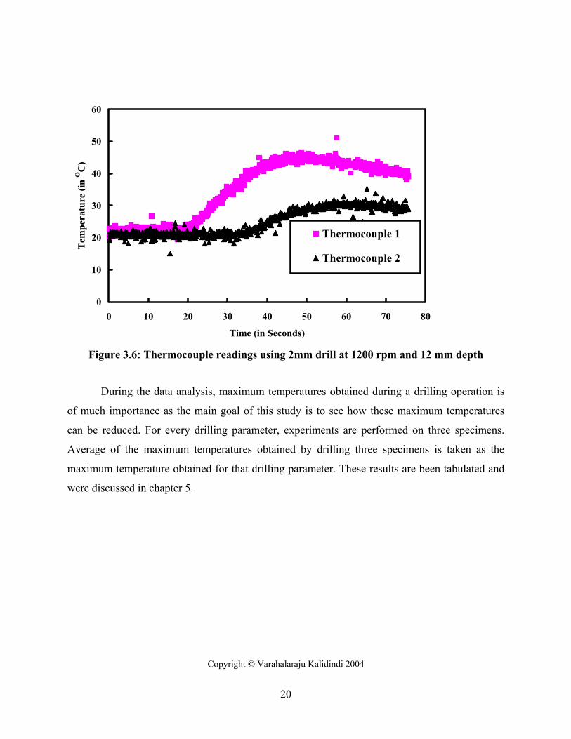
Figure 3.6: Thermocouple readings using 2mm drill at 1200 rpm and 12 mm depth
During the data analysis, maximum temperatures obtained during a drilling operation is
of much importance as the main goal of this study is to see how these maximum temperatures
can be reduced. For every drilling parameter, experiments are performed on three specimens.
Average of the maximum temperatures obtained by drilling three specimens is taken as the
maximum temperature obtained for that drilling parameter. These results are been tabulated and
were discussed in chapter 5.
Copyright © Varahalaraju Kalidindi 2004
21
CHAPTER 4
THEORETICAL EQUATION
4.1 MODELING APPROACH In order to build a predictive model for the temperature and heat flux in the current
problem, a global pattern for the heat distribution must be determined. The predictive model will
help dentists to scale the temperature profiles and the amount of heat flux entering into the
human bone during drilling operation. Therefore, proper drilling parameters can be chosen.
Finite element analysis is carried out on PMMA model and also thermograph images are
taken using infrared camera process to check how heat spreads out during drilling process for
formulating a theoretical model.
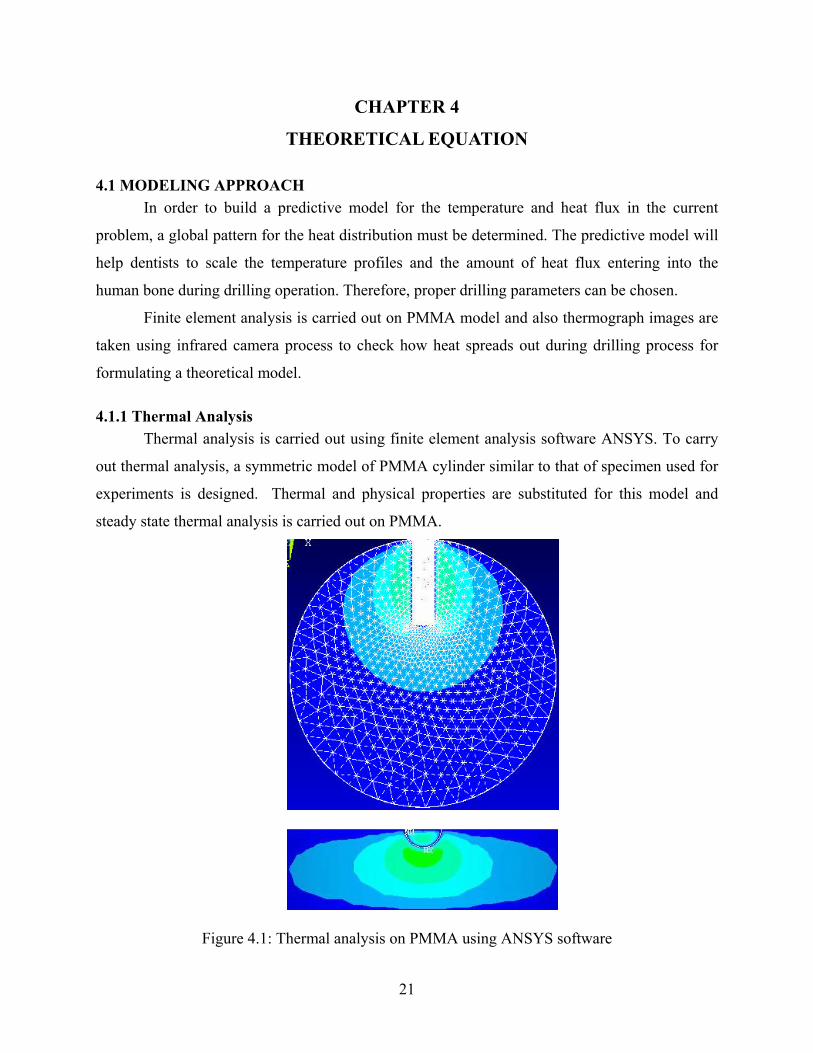
4.1.1 Thermal Analysis Thermal analysis is carried out using finite element analysis software ANSYS. To carry
out thermal analysis, a symmetric model of PMMA cylinder similar to that of specimen used for
experiments is designed. Thermal and physical properties are substituted for this model and
steady state thermal analysis is carried out on PMMA.
Figure 4.1: Thermal analysis on PMMA using ANSYS software
22
Results from thermal analysis shows that the heat generated during the drilling process spreads
out in radial direction across the model.
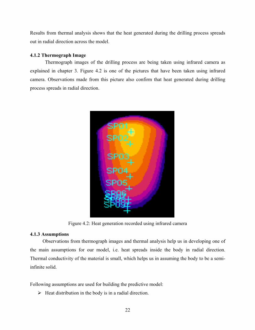
4.1.2 Thermograph Image Thermograph images of the drilling process are being taken using infrared camera as
explained in chapter 3. Figure 4.2 is one of the pictures that have been taken using infrared
camera. Observations made from this picture also confirm that heat generated during drilling
process spreads in radial direction.
Figure 4.2: Heat generation recorded using infrared camera
4.1.3 Assumptions Observations from thermograph images and thermal analysis help us in developing one of
the main assumptions for our model, i.e. heat spreads inside the body in radial direction.
Thermal conductivity of the material is small, which helps us in assuming the body to be a semi-
infinite solid.
Following assumptions are used for building the predictive model:
Heat distribution in the body is in a radial direction.
23
Body is considered to be semi-infinite solid.
4.2 DERIVATION Drilling procedure inside PMMA cylinder increase temperature. There are many drilling
factors like drill speed, depth of the drilling, drill diameter and others, which affect the
temperature increase. In this section an equation is derived to predict the temperature rise as the
function of these drilling parameters. Equation is being derived based upon the above
assumptions.
Consider the homogenous differential equation of heat conduction in the cylindrical
coordination system,
tT1
rT
r1
rT
12
2
∂∂
=∂∂
+∂∂
α For ∞<≤ ra (4.1)
Where temperature T is a function of radius r and time t. 1α is the thermal diffusivity of the
material.
Boundary conditions are as follows:
At ar = , kq
rT
−=∂∂ q is the constant heat flux being generated. (4.1.1)
At ∞=r , 0=∂∂
rT we assume heat flux is zero at infinite boundary. (4.1.2)
Initial condition:
For 0=t , RTT = RT is the room temperature. (4.1.3)
We define dimensionless parameters to convert non-homogenous boundary conditions into
homogenous boundary conditions as follows:
Rcc
R TTTTTT
+∆=⇒∆−
= θθ (4.2.1)
cc
rrrr ηη =⇒= (4.2.2)
cc
O ttttF ττ =⇒== . (4.2.3)
24
Where θ is the dimensionless temperature, η is the dimensionless radius, τ is the
dimensionless time and OF is Fourier number, cr is radius of the drill, ct is the time at which we
start drilling and we define qak
qrkT
cc −=−=∆ .
After substituting the dimensionless parameters in Equation (4.1) we get the following
differential equation:
τθ
ηθ
ηηθ
∂∂
=∂∂
+∂∂ 1
2
2
For ∞<≤η1 (4.3)
The boundary conditions are as follows:
At .1,1 =∂∂
=ηθη (4.3.1)
At .0, =∂∂
∞→ηθη (4.3.2)
At .0,0 == θτ (4.3.3)
The equation (4.3) is dependant on both η andτ . To solve the problem let us define .4
2
τηυ =
(4.4)
Differentiating (4.4) both with respect to τη and we get:
.22 τη
ηυη
τηυ =
∂∂
⇒∂=∂ (4.4.1)
.44 2
2
2
2
τη
τυτ
τηυ −=
∂∂
⇒∂−=∂ (4.4.2)
Substituting the above in Equation (3.0) we get
τθ
ηθ
ηηθ
∂∂
=∂∂
+∂∂ 1
2
2
τυ
υθ
ηυ
υθ
ηηυ
ηυ
υθ
υ ∂∂
∂∂
=∂∂
∂∂
+∂∂
∂∂
∂∂ 1
dd
25
υθ
τη
τη
υθ
ητη
τη
υθ
υ ∂∂
−=∂∂
+
∂∂
∂∂
2
2
421
22
υθ
τη
υθ
τυθ
τη
dd
dd
dd
2
2
2
2
2
2
421
4−=+
υθ
τυ
υθ
τυθ
τυ
dd
dd
dd
−=+21
2
2
Dividing the above equation by τυ we get,
υθ
υθ
ϑυθ
dd
dd
dd
−=+21
2
2
0121
2
2
=
++
υθ
υυθ
dd
dd . (4.5)
The boundary conditions will be changed as follows:
As τητ
υθ
ηυ
υθ
ηθ
τυη 2211.
411 ==⇒=
∂∂
⇒=∂∂
=⇒=dd
dd (4.5.1)
As ∞→⇒∞→ υη , 00 =⇒=∂∂
υθ
ηθ
dd . (4.5.2)
At ∞→= υτ ,0 , 0=υθ
dd . (4.5.3)
Let us define ydd
=υθ then the equation (4.5) would be as follows:
0121
=
++ y
ddy
υυ. (4.6)
This equation is of the form:
QPydxdy
=+ (4.7)
The solution of the above equation is:
∫+∫∫=−−
∫PdxPdxPdx
eCdxQeey 1 . [33]
Comparing the Equation(6) and Equation(7) we have .0,121
=+= QPυ
The solution would be:
26
∫=
+− υ
υd
eCy1
21
1
= υ
υ−eC1 .
Also,
.1υυ
θ υ−
=eC
dd
At boundary conditionτ
υ41
= we have .2
41
2 41
1
41
1τ
τ
ττ
τ
τυθ eCeC
dd
=⇒=⇒=−
υυ
θυ
deCd−
= 1 .
Integrating on both sides we get,
2
41
10
CdeCd += ∫∫∞ −
υυ
θ
τ
νθ
.
Let us consider the following integral:
.11
1)1(0
1 dttex
vvdt
te x
v
tv
xv
t
∫∫−
−∞ − −
+−
−−Γ= [34]
We need υυ
τ
υ
de∫∞ −
41
, comparing the above two equations we have τ41,5.0 == xv hence we get
υυτ
υυ
τ υ
τ
υ
dede∫∫
−−∞ − −+
−−−Γ=
41
0
5.01
41
141
5.011)5.01(
.11)5.0(41
0
υυτ
τ υ
de∫
−−+−Γ=
also here [ ] ττ υ
υπυυυ
41
0
41
0
)(**21 erfde−=
−∫
−
27
)2
1(1τ
πτ
erf−=
Hence we get
).2
1(*11)5.0(
41 τ
πττ
υυ
τ
υ
erfde−+−Γ=∫
∞ −
)2
1(*)5.0(
41 τ
πυυ
τ
υ
erfde−Γ=∫
∞ −
.
Hence we have the final equation as
( )
−=
−Γ=
τπτ
τπτθ
τ
τ
21*775.1
)2
1(5.0
41
41
erfe
erfe
Substituting back the value of τ from our previous assumptions, we get
−= )
t2a(erf*775.1e
at
1
1t4
2a
1
απ
αθ α
But we know that TTqak
kqaTT
RR =+−⇒
−−=
θθ)(
. Substituting this expression we get the
final equation as follows:
−−= )
t2a(erf*775.1e
qatkTT
1
1t4
2a
2
1R α
πα α (4.8)
The above expression gives expression for temperature rise during drilling process as a
function of heat flux (q), thermal conductivity (k), time taken for drilling (t), and thermal
diffusivity (α1). Here we know the values of thermal conductivity and thermal diffusivity of
PMMA, and also the time taken for drilling process. We need to determine the value of heat flux
(q) generated during drilling process.
28
Amount of heat flux generated during drilling process depends on many drilling
parameters. In the next few steps I am going to explain in detail how the expression is derived
for heat flux during drilling process.
4.3 EXPRESSION FOR HEAT FLUX Energy involved in material removal is converted into heat. The heat generated is
therefore well approximated by the amount of work done.
SS vFtQ=
∂∂ [35] (4.9)
where Q is the heat generated by the cutting action, t is time, SF is the shearing force in
the shear plane, Sv is the shear velocity.
4.3.1 Calculation of shear velocity
The shear velocity Sv is related to cutting velocity v and shear angle φ as
φcos
vvS = (4.10)
Shear angle φ is calculated using the Ernst-Merchant relationship, 2 090=−+ αβφ .
Where α is rake angle of the cutting tool and the friction angle, β , is equal to 0.644 [37]
An expression for α at a distance r from the rotational axis was developed by Battacharya
and Ham [38], as follows:
( ) ( ) ( )[ ] ( )
( )psinpcospsinr2/dsintantanD/r2
tan 01−−
=θ
α (4.11)
where D is the drill diameter, 0d is chisel edge diameter, θ is the helix angle, and p is the half-
angle at the point.
29
The velocity v can be calculated as follows:
60rN2v π
= where N is the rotational speed, in rpm. (4.12)
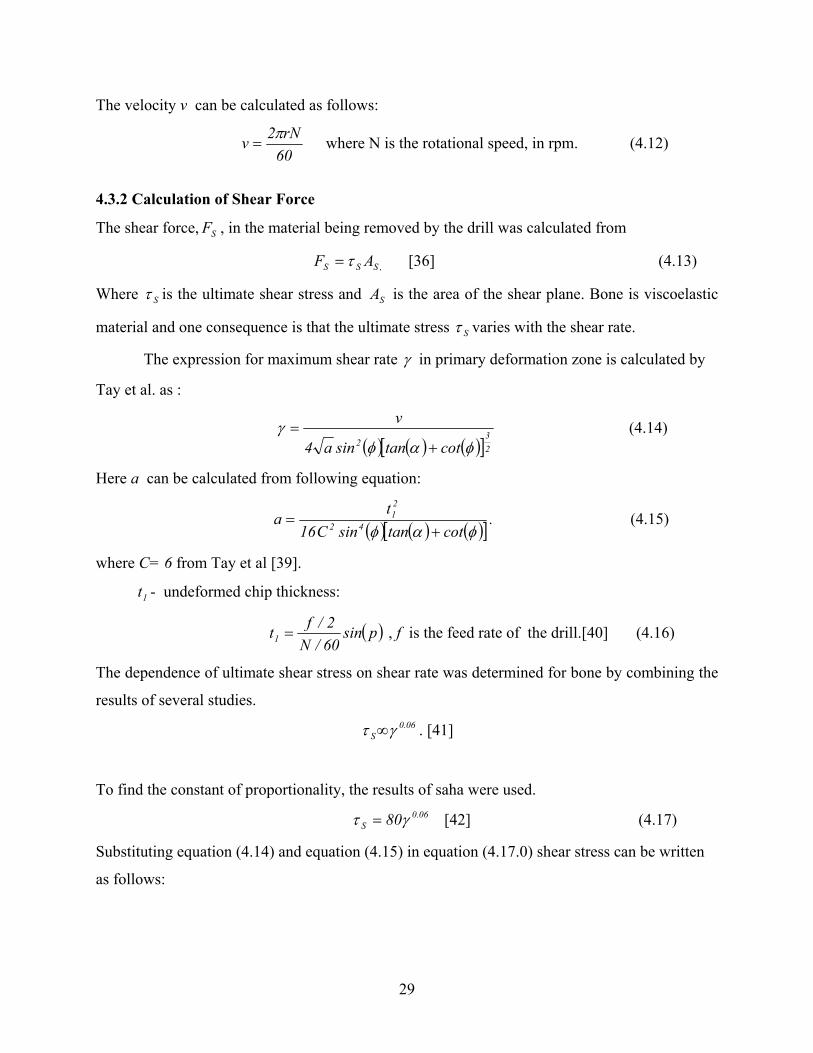
4.3.2 Calculation of Shear Force
The shear force, SF , in the material being removed by the drill was calculated from
,SSS AF τ= [36] (4.13)
Where Sτ is the ultimate shear stress and SA is the area of the shear plane. Bone is viscoelastic
material and one consequence is that the ultimate stress Sτ varies with the shear rate.
The expression for maximum shear rate γ in primary deformation zone is calculated by
Tay et al. as :
( ) ( ) ( )[ ]2
32 cottansina4
v
φαφγ
+= (4.14)
Here a can be calculated from following equation:
( ) ( ) ( )[ ] .cottansinC16ta 42
21
φαφ += (4.15)
where C= 6 from Tay et al [39].
1t - undeformed chip thickness:
( )psin60/N2/ft1 = , f is the feed rate of the drill.[40] (4.16)
The dependence of ultimate shear stress on shear rate was determined for bone by combining the
results of several studies. 06.0
S γτ ∞ . [41]
To find the constant of proportionality, the results of saha were used.
06.0S 80γτ = [42] (4.17)
Substituting equation (4.14) and equation (4.15) in equation (4.17.0) shear stress can be written
as follows:
30
( ) ( ) ( )[ ] ( ) ( ) ( )[ ]
06.0
23
242
21
S
cottansincottansinC16
t4
v80
+
+
=
φαφφαφ
τ
( ) ( )[ ]
06.0
1 cottantvC80
+
=φα
(4.18)
The shear plane area,
( )
( ) ( )psinp90cosdDt
A 001
S −−
= (4.19)
We know from Equation(13)
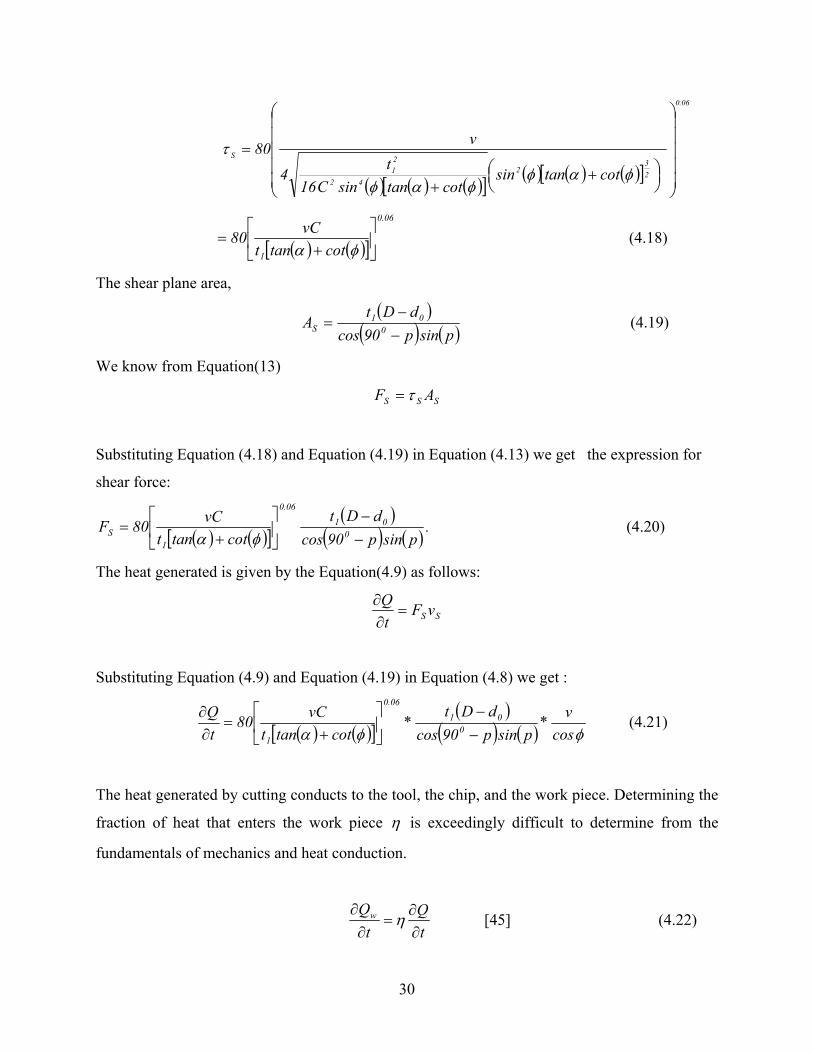
SSS AF τ=
Substituting Equation (4.18) and Equation (4.19) in Equation (4.13) we get the expression for
shear force:
( ) ( )[ ]( )
( ) ( ) .psinp90cos
dDtcottant
vC80F 001
06.0
1S −
−
+
=φα
(4.20)
The heat generated is given by the Equation(4.9) as follows:
SS vFtQ=
∂∂
Substituting Equation (4.9) and Equation (4.19) in Equation (4.8) we get :
( ) ( )[ ]( )
( ) ( ) φφα cosv*
psinp90cosdDt
*cottant
vC80tQ
001
06.0
1 −−
+
=∂∂ (4.21)
The heat generated by cutting conducts to the tool, the chip, and the work piece. Determining the
fraction of heat that enters the work piece η is exceedingly difficult to determine from the
fundamentals of mechanics and heat conduction.
tQ
tQw
∂∂
=∂∂
η [45] (4.22)
31
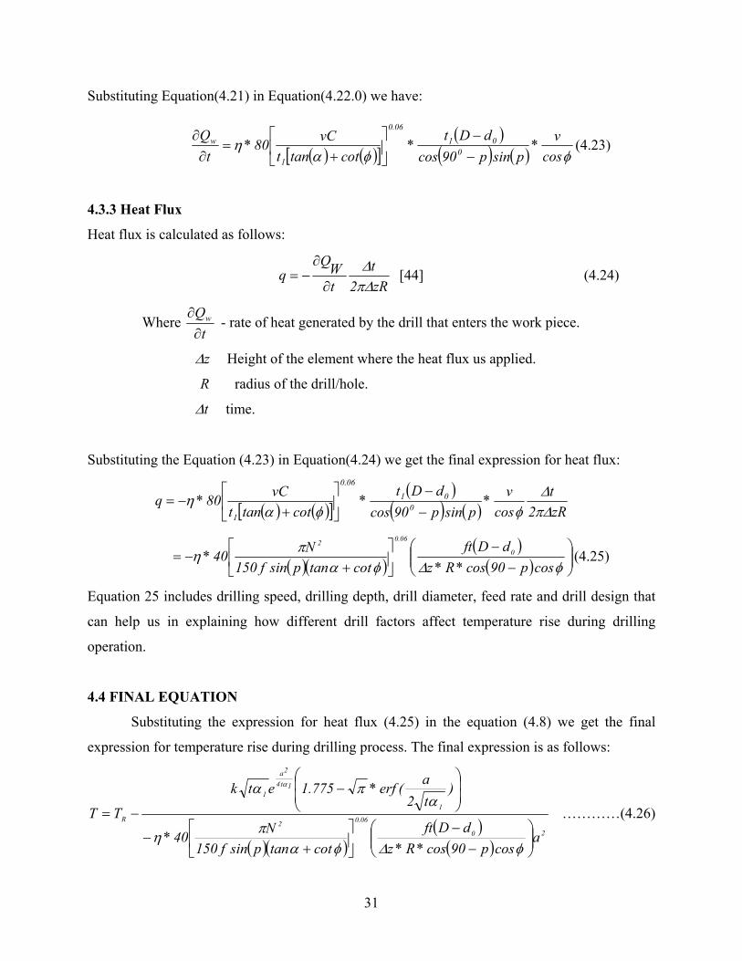
Substituting Equation(4.21) in Equation(4.22.0) we have:
( ) ( )[ ]( )
( ) ( ) φφαη
cosv*
psinp90cosdDt
*cottant
vC80*t
Q0
0106.0
1
w
−−
+
=∂∂
(4.23)
4.3.3 Heat Flux
Heat flux is calculated as follows:
zR2t
tWQ
q∆π∆
∂
∂−= [44] (4.24)
Where t
Qw
∂∂
- rate of heat generated by the drill that enters the work piece.
z∆ Height of the element where the heat flux us applied.
R radius of the drill/hole.
t∆ time.
Substituting the Equation (4.23) in Equation(4.24) we get the final expression for heat flux:
( ) ( )[ ]( )
( ) ( ) zR2t
cosv*
psinp90cosdDt
*cottant
vC80*q 001
06.0
1 ∆π∆
φφαη
−−
+
−=
( )( )( )( )
−
−
+
−=φ∆φα
πηcosp90cos*R*z
dDftcottanpsinf150
N40* 0
06.02
(4.25)
Equation 25 includes drilling speed, drilling depth, drill diameter, feed rate and drill design that
can help us in explaining how different drill factors affect temperature rise during drilling
operation.
4.4 FINAL EQUATION
Substituting the expression for heat flux (4.25) in the equation (4.8) we get the final
expression for temperature rise during drilling process. The final expression is as follows:
( )( )( )( )
20
06.02
1
1t4
2a
1
R
acosp90cos*R*z
dDftcottanpsinf150
N40*
)t2a(erf*775.1etk
TT
−
−
+
−
−
−=
φ∆φαπη
απα α
…………(4.26)
32
4.5 NOMENCLATURE
RT Room temperature
1α Thermal diffusivity of the material.
k Thermal conductivity of the material.
t Time taken for drilling.(sec)
N Drill speed in R.P.M.
F Drill feed rate in m/sec.
z∆ Height of the element where the heat flux is applied or Drilling Depth (m)
a Radius of the hole (m).
η Fraction of heat that enters the work piece.
D Drill diameter (m),
0d Chisel edge diameter of the tool (m),
θ Helix angle of the cutting tool,
p Half-angle at the point.
α Rake angle of the cutting tool.
Copyright © Varahalaraju Kalidindi 2004
33
CHAPTER 5
RESULTS & DISCUSSION
This chapter is divided into two main sections. In the first section, experimental results
obtained by drilling PMMA with different drilling parameters are being presented. Experiments
were carried out to check how different drilling parameters: speed, depth, bit diameter, feed rate,
external coolant and also comparison between temperatures obtained using single step drilling
procedure and incremental drilling procedures were made on PMMA. Comparisons of
temperatures obtained from theoretical model and experiments were made in the second section
of this chapter to validate thermal model developed. Comparison of temperature profiles
obtained from theoretical model is also made between PMMA and human bone.
5.1 EXPERIMENTAL RESULTS
This section includes results obtained from experiments and a brief discussion about the
results. Series of experiments were carried out to check how variable drilling conditions would
affect the temperature increase. Number of PMMA samples has been prepared for testing.
Experiments are carried out on three similar PMMA samples for a particular drilling parameter,
which is to be tested by having other drilling parameters constant.
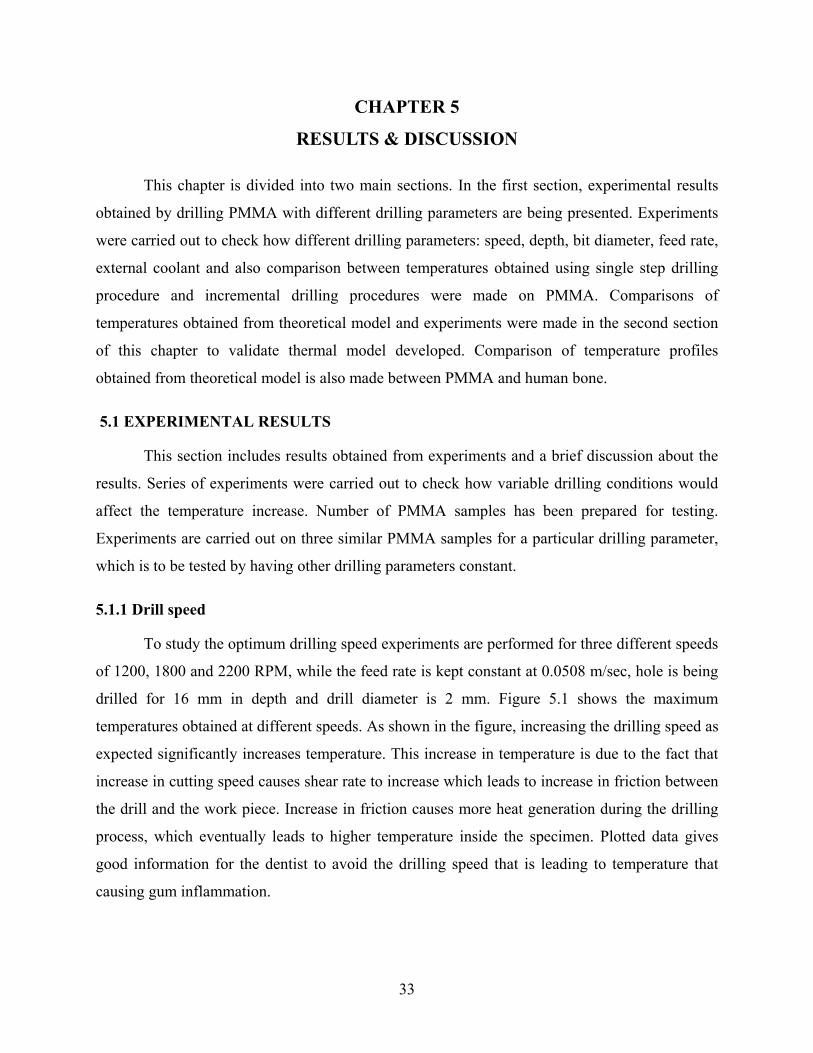
5.1.1 Drill speed
To study the optimum drilling speed experiments are performed for three different speeds
of 1200, 1800 and 2200 RPM, while the feed rate is kept constant at 0.0508 m/sec, hole is being
drilled for 16 mm in depth and drill diameter is 2 mm. Figure 5.1 shows the maximum
temperatures obtained at different speeds. As shown in the figure, increasing the drilling speed as
expected significantly increases temperature. This increase in temperature is due to the fact that
increase in cutting speed causes shear rate to increase which leads to increase in friction between
the drill and the work piece. Increase in friction causes more heat generation during the drilling
process, which eventually leads to higher temperature inside the specimen. Plotted data gives
good information for the dentist to avoid the drilling speed that is leading to temperature that
causing gum inflammation.
34
0
10
20
30
40
50
60
1000 1200 1400 1600 1800 2000 2200 2400
Drill Speed (in RPM)
Tem
pera
ture
(in O
C)
Figure 5.1:Temperatures at drilling speed of 1200,1800 and 2200 RPM
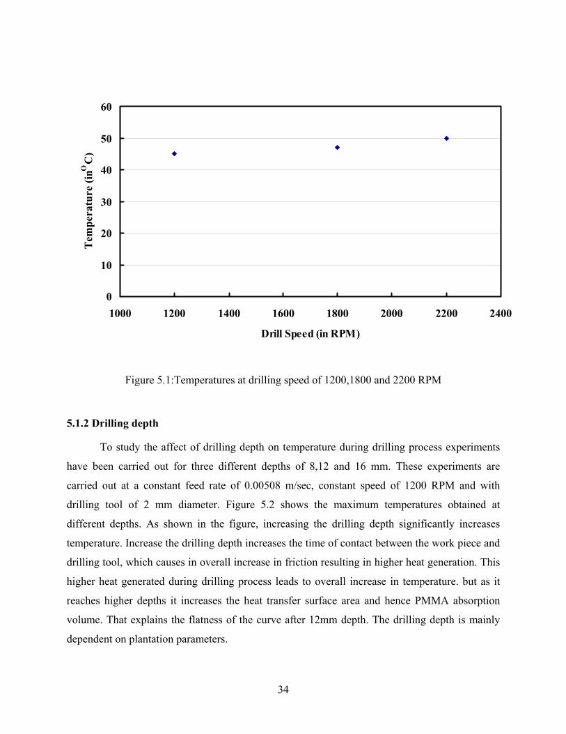
5.1.2 Drilling depth
To study the affect of drilling depth on temperature during drilling process experiments
have been carried out for three different depths of 8,12 and 16 mm. These experiments are
carried out at a constant feed rate of 0.00508 m/sec, constant speed of 1200 RPM and with
drilling tool of 2 mm diameter. Figure 5.2 shows the maximum temperatures obtained at
different depths. As shown in the figure, increasing the drilling depth significantly increases
temperature. Increase the drilling depth increases the time of contact between the work piece and
drilling tool, which causes in overall increase in friction resulting in higher heat generation. This
higher heat generated during drilling process leads to overall increase in temperature. but as it
reaches higher depths it increases the heat transfer surface area and hence PMMA absorption
volume. That explains the flatness of the curve after 12mm depth. The drilling depth is mainly
dependent on plantation parameters.
35
0
5
10
15
20
25
30
35
40
45
50
6 8 10 12 14 16 18
Depth (in mm)
Tem
pera
ture
(in
OC
)
8 mm
12 mm16 mm
Figure 5.2: Temperatures measured at drilling depths of 8,12,16 mm
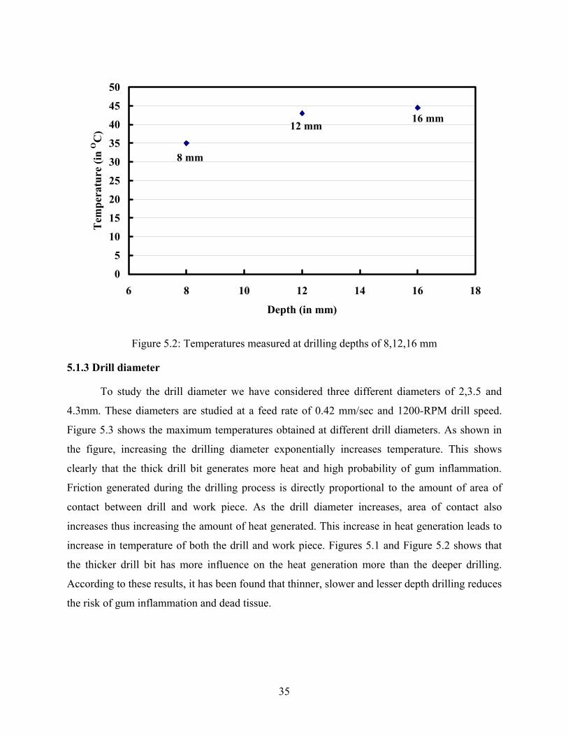
5.1.3 Drill diameter
To study the drill diameter we have considered three different diameters of 2,3.5 and
4.3mm. These diameters are studied at a feed rate of 0.42 mm/sec and 1200-RPM drill speed.
Figure 5.3 shows the maximum temperatures obtained at different drill diameters. As shown in
the figure, increasing the drilling diameter exponentially increases temperature. This shows
clearly that the thick drill bit generates more heat and high probability of gum inflammation.
Friction generated during the drilling process is directly proportional to the amount of area of
contact between drill and work piece. As the drill diameter increases, area of contact also
increases thus increasing the amount of heat generated. This increase in heat generation leads to
increase in temperature of both the drill and work piece. Figures 5.1 and Figure 5.2 shows that
the thicker drill bit has more influence on the heat generation more than the deeper drilling.
According to these results, it has been found that thinner, slower and lesser depth drilling reduces
the risk of gum inflammation and dead tissue.
36
0
10
20
30
40
50
60
70
80
1 1.5 2 2.5 3 3.5 4 4.5
Drill Diameter (in mm)
Tem
pera
ture
(in
OC
)
2 mm 3.5 mm
4.3 mm
Figure 5.3: Temperatures measured with drills of 2,3.5and 4.3 mm diameter
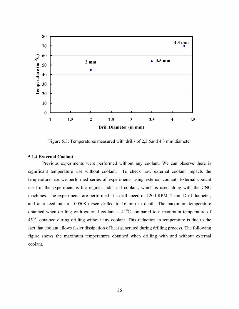
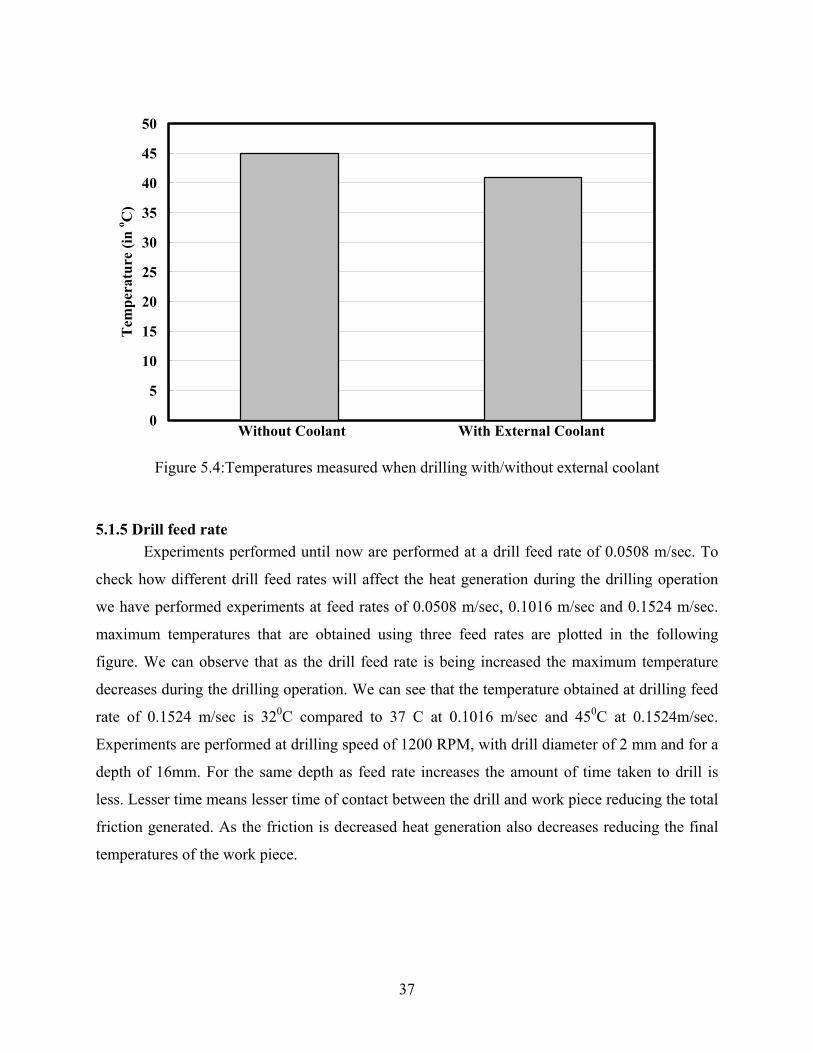
5.1.4 External Coolant Previous experiments were performed without any coolant. We can observe there is
significant temperature rise without coolant. To check how external coolant impacts the
temperature rise we performed series of experiments using external coolant. External coolant
used in the experiment is the regular industrial coolant, which is used along with the CNC
machines. The experiments are performed at a drill speed of 1200 RPM, 2 mm Drill diameter,
and at a feed rate of .00508 m/sec drilled to 16 mm in depth. The maximum temperature
obtained when drilling with external coolant is 410C compared to a maximum temperature of
450C obtained during drilling without any coolant. This reduction in temperature is due to the
fact that coolant allows faster dissipation of heat generated during drilling process. The following
figure shows the maximum temperatures obtained when drilling with and without external
coolant.
37
0
5
10
15
20
25
30
35
40
45
50T
empe
ratu
re (i
n o C
)
Without Coolant With External Coolant
Figure 5.4:Temperatures measured when drilling with/without external coolant
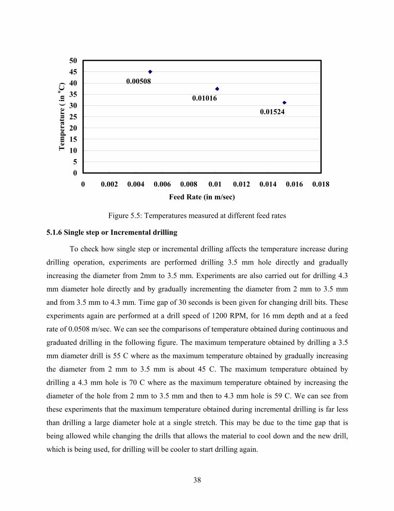
5.1.5 Drill feed rate Experiments performed until now are performed at a drill feed rate of 0.0508 m/sec. To
check how different drill feed rates will affect the heat generation during the drilling operation
we have performed experiments at feed rates of 0.0508 m/sec, 0.1016 m/sec and 0.1524 m/sec.
maximum temperatures that are obtained using three feed rates are plotted in the following
figure. We can observe that as the drill feed rate is being increased the maximum temperature
decreases during the drilling operation. We can see that the temperature obtained at drilling feed
rate of 0.1524 m/sec is 320C compared to 37 C at 0.1016 m/sec and 450C at 0.1524m/sec.
Experiments are performed at drilling speed of 1200 RPM, with drill diameter of 2 mm and for a
depth of 16mm. For the same depth as feed rate increases the amount of time taken to drill is
less. Lesser time means lesser time of contact between the drill and work piece reducing the total
friction generated. As the friction is decreased heat generation also decreases reducing the final
temperatures of the work piece.
38
05
101520253035404550
0 0.002 0.004 0.006 0.008 0.01 0.012 0.014 0.016 0.018
Feed Rate (in m/sec)
Tem
pera
ture
( in
o C) 0.00508
0.01016
0.01524
Figure 5.5: Temperatures measured at different feed rates
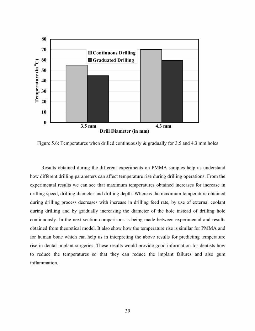
5.1.6 Single step or Incremental drilling
To check how single step or incremental drilling affects the temperature increase during
drilling operation, experiments are performed drilling 3.5 mm hole directly and gradually
increasing the diameter from 2mm to 3.5 mm. Experiments are also carried out for drilling 4.3
mm diameter hole directly and by gradually incrementing the diameter from 2 mm to 3.5 mm
and from 3.5 mm to 4.3 mm. Time gap of 30 seconds is been given for changing drill bits. These
experiments again are performed at a drill speed of 1200 RPM, for 16 mm depth and at a feed
rate of 0.0508 m/sec. We can see the comparisons of temperature obtained during continuous and
graduated drilling in the following figure. The maximum temperature obtained by drilling a 3.5
mm diameter drill is 55 C where as the maximum temperature obtained by gradually increasing
the diameter from 2 mm to 3.5 mm is about 45 C. The maximum temperature obtained by
drilling a 4.3 mm hole is 70 C where as the maximum temperature obtained by increasing the
diameter of the hole from 2 mm to 3.5 mm and then to 4.3 mm hole is 59 C. We can see from
these experiments that the maximum temperature obtained during incremental drilling is far less
than drilling a large diameter hole at a single stretch. This may be due to the time gap that is
being allowed while changing the drills that allows the material to cool down and the new drill,
which is being used, for drilling will be cooler to start drilling again.
39
0
10
20
30
40
50
60
70
80
Drill Diameter (in mm)
Tem
pera
ture
(in
o C)
Continuous DrillingGraduated Drilling
3.5 mm 4.3 mm
Figure 5.6: Temperatures when drilled continuously & gradually for 3.5 and 4.3 mm holes
Results obtained during the different experiments on PMMA samples help us understand
how different drilling parameters can affect temperature rise during drilling operations. From the
experimental results we can see that maximum temperatures obtained increases for increase in
drilling speed, drilling diameter and drilling depth. Whereas the maximum temperature obtained
during drilling process decreases with increase in drilling feed rate, by use of external coolant
during drilling and by gradually increasing the diameter of the hole instead of drilling hole
continuously. In the next section comparisons is being made between experimental and results
obtained from theoretical model. It also show how the temperature rise is similar for PMMA and
for human bone which can help us in interpreting the above results for predicting temperature
rise in dental implant surgeries. These results would provide good information for dentists how
to reduce the temperatures so that they can reduce the implant failures and also gum
inflammation.
40
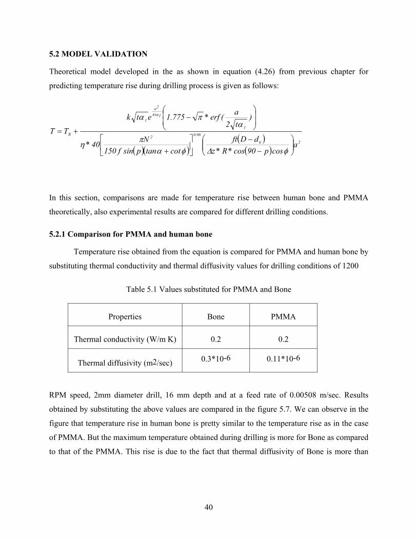
5.2 MODEL VALIDATION
Theoretical model developed in the as shown in equation (4.26) from previous chapter for
predicting temperature rise during drilling process is given as follows:
( )( )( )( )
20
06.02
1
1t4
2a
1
R
acosp90cos*R*z
dDftcottanpsinf150
N40*
)t2a(erf*775.1etk
TT
−
−
+
−
+=
φ∆φαπη
απα α
In this section, comparisons are made for temperature rise between human bone and PMMA
theoretically, also experimental results are compared for different drilling conditions.
5.2.1 Comparison for PMMA and human bone
Temperature rise obtained from the equation is compared for PMMA and human bone by
substituting thermal conductivity and thermal diffusivity values for drilling conditions of 1200
Table 5.1 Values substituted for PMMA and Bone
Properties Bone PMMA
Thermal conductivity (W/m K) 0.2 0.2
Thermal diffusivity (m2/sec) 0.3*10-6 0.11*10-6
RPM speed, 2mm diameter drill, 16 mm depth and at a feed rate of 0.00508 m/sec. Results
obtained by substituting the above values are compared in the figure 5.7. We can observe in the
figure that temperature rise in human bone is pretty similar to the temperature rise as in the case
of PMMA. But the maximum temperature obtained during drilling is more for Bone as compared
to that of the PMMA. This rise is due to the fact that thermal diffusivity of Bone is more than
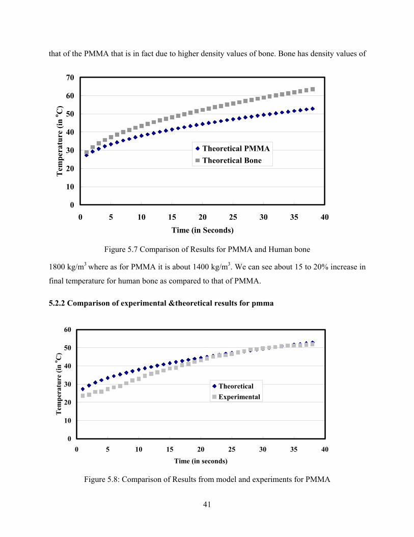
41
that of the PMMA that is in fact due to higher density values of bone. Bone has density values of
0
10
20
30
40
50
60
70
0 5 10 15 20 25 30 35 40Time (in Seconds)
Tem
pera
ture
(in
o C)
Theoretical PMMATheoretical Bone
Figure 5.7 Comparison of Results for PMMA and Human bone
1800 kg/m3 where as for PMMA it is about 1400 kg/m3. We can see about 15 to 20% increase in
final temperature for human bone as compared to that of PMMA.
5.2.2 Comparison of experimental &theoretical results for pmma
0
10
20
30
40
50
60
0 5 10 15 20 25 30 35 40Time (in seconds)
Tem
pera
ture
(in
o C)
TheoreticalExperimental
Figure 5.8: Comparison of Results from model and experiments for PMMA
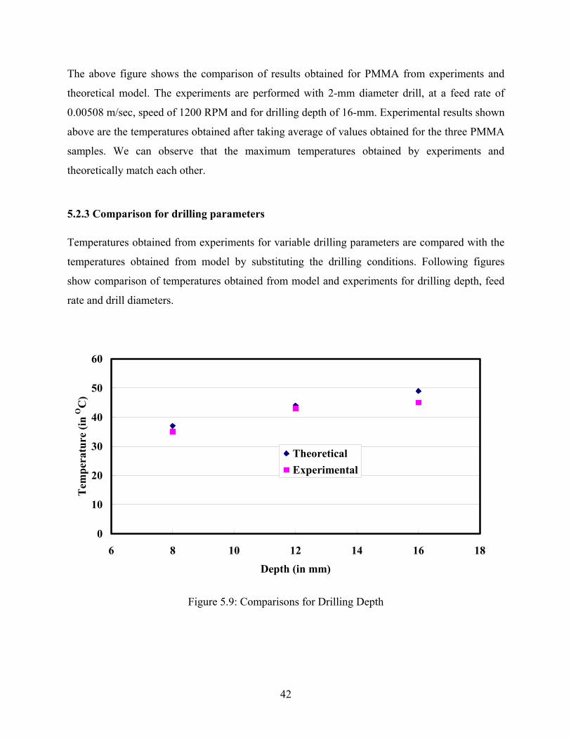
42
The above figure shows the comparison of results obtained for PMMA from experiments and
theoretical model. The experiments are performed with 2-mm diameter drill, at a feed rate of
0.00508 m/sec, speed of 1200 RPM and for drilling depth of 16-mm. Experimental results shown
above are the temperatures obtained after taking average of values obtained for the three PMMA
samples. We can observe that the maximum temperatures obtained by experiments and
theoretically match each other.
5.2.3 Comparison for drilling parameters Temperatures obtained from experiments for variable drilling parameters are compared with the
temperatures obtained from model by substituting the drilling conditions. Following figures
show comparison of temperatures obtained from model and experiments for drilling depth, feed
rate and drill diameters.
0
10
20
30
40
50
60
6 8 10 12 14 16 18
Depth (in mm)
Tem
pera
ture
(in
OC
)
TheoreticalExperimental
Figure 5.9: Comparisons for Drilling Depth
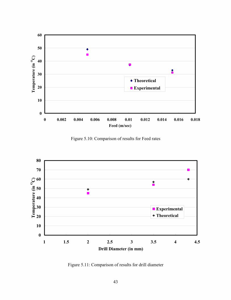
43
0
10
20
30
40
50
60
0 0.002 0.004 0.006 0.008 0.01 0.012 0.014 0.016 0.018Feed (m/sec)
Tem
pera
ture
(in
OC
)
TheoreticalExperimental
Figure 5.10: Comparison of results for Feed rates
0
10
20
30
40
50
60
70
80
1 1.5 2 2.5 3 3.5 4 4.5Drill Diameter (in mm)
Tem
pera
ture
(in
OC
)
ExperimentalTheoretical
Figure 5.11: Comparison of results for drill diameter
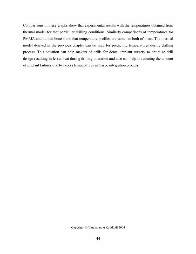
44
Comparisons in these graphs show that experimental results with the temperatures obtained from
thermal model for that particular drilling conditions. Similarly comparisons of temperatures for
PMMA and human bone show that temperature profiles are same for both of them. The thermal
model derived in the previous chapter can be used for predicting temperatures during drilling
process. This equation can help makers of drills for dental implant surgery to optimize drill
design resulting in lesser heat during drilling operation and also can help in reducing the amount
of implant failures due to excess temperatures in Osseo integration process.
Copyright © Varahalaraju Kalidindi 2004
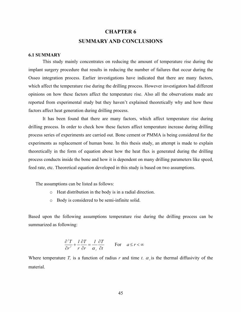
45
CHAPTER 6
SUMMARY AND CONCLUSIONS
6.1 SUMMARY This study mainly concentrates on reducing the amount of temperature rise during the
implant surgery procedure that results in reducing the number of failures that occur during the
Osseo integration process. Earlier investigations have indicated that there are many factors,
which affect the temperature rise during the drilling process. However investigators had different
opinions on how these factors affect the temperature rise. Also all the observations made are
reported from experimental study but they haven’t explained theoretically why and how these
factors affect heat generation during drilling process.
It has been found that there are many factors, which affect temperature rise during
drilling process. In order to check how these factors affect temperature increase during drilling
process series of experiments are carried out. Bone cement or PMMA is being considered for the
experiments as replacement of human bone. In this thesis study, an attempt is made to explain
theoretically in the form of equation about how the heat flux is generated during the drilling
process conducts inside the bone and how it is dependent on many drilling parameters like speed,
feed rate, etc. Theoretical equation developed in this study is based on two assumptions.
The assumptions can be listed as follows:
o Heat distribution in the body is in a radial direction.
o Body is considered to be semi-infinite solid.
Based upon the following assumptions temperature rise during the drilling process can be
summarized as following:
tT1
rT
r1
rT
12
2
∂∂
=∂∂
+∂∂
α For ∞<≤ ra
Where temperature T, is a function of radius r and time t. 1α is the thermal diffusivity of the
material.
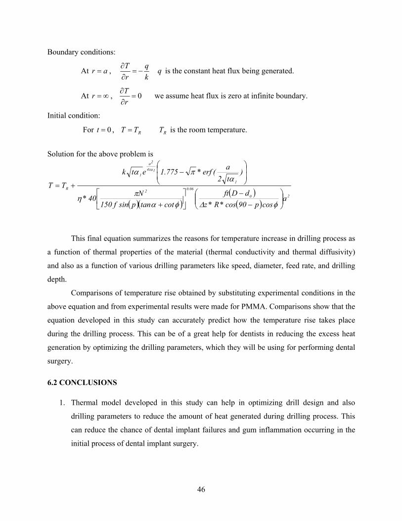
46
Boundary conditions:
At ar = , kq
rT
−=∂∂ q is the constant heat flux being generated.
At ∞=r , 0=∂∂
rT we assume heat flux is zero at infinite boundary.
Initial condition:
For 0=t , RTT = RT is the room temperature.
Solution for the above problem is
( )( )( )( )
20
06.02
1
1t4
2a
1
R
acosp90cos*R*z
dDftcottanpsinf150
N40*
)t2a(erf*775.1etk
TT
−
−
+
−
+=
φ∆φαπη
απα α
This final equation summarizes the reasons for temperature increase in drilling process as
a function of thermal properties of the material (thermal conductivity and thermal diffusivity)
and also as a function of various drilling parameters like speed, diameter, feed rate, and drilling
depth.
Comparisons of temperature rise obtained by substituting experimental conditions in the
above equation and from experimental results were made for PMMA. Comparisons show that the
equation developed in this study can accurately predict how the temperature rise takes place
during the drilling process. This can be of a great help for dentists in reducing the excess heat
generation by optimizing the drilling parameters, which they will be using for performing dental
surgery.
6.2 CONCLUSIONS
1. Thermal model developed in this study can help in optimizing drill design and also
drilling parameters to reduce the amount of heat generated during drilling process. This
can reduce the chance of dental implant failures and gum inflammation occurring in the
initial process of dental implant surgery.
47
2. Experiments during this study show how variable drilling parameters like drilling speed,
depth, bit diameter, and feed rate affect the heat generation. Graphs shown in the chapter
5 explain the trend in temperature rise or decrease as the parameters are changed. These
results are also confirmed with the results obtained from theoretical model.
3. This study also suggests that the drilling process carried out step-by-step increase of
diameter rather than drilling in a single step with the same drill would reduce the
temperature rise thus reducing risk of death tissue.
4. Use of external coolant is also suggested for avoiding higher temperatures.
5. This study provides good information for the dentist in avoiding the drilling conditions
that can lead to temperatures causing gum inflammation and death tissue.
6.3 FUTURE WORK Experiments performed here are under in vivo conditions and are also performed on
PMMA. To accurately predict the exact temperatures during dental implant surgery experiments
are to be conducted on live specimen using infrared camera and these results should be compared
with the temperatures obtained from the model developed in this study. Also experiments are to
be performed to study the impact of internal irrigation and different coolants on temperatures
produced during drilling operations. Also the model cannot predict the affect of drill sharpness
on temperature rise.
COPYRIGHT © VARAHALARAJU KALIDINDI 2004
48
APPENDIX 1
NOMENCLATURE
T Final temperature after drilling
1α Thermal diffusivity of the material.
RT Room temperature
k Thermal conductivity of the material.
q Heat flux generated during drilling.
t Time taken for drilling in sec.
N Drill speed in R.P.M.
F Drill feed rate in m/sec.
z∆ Height of the element where the heat flux is applied or Drilling Depth (m)
a Radius of the hole (m).
η Fraction of heat that enters the work piece.
D Drill diameter (m),
0d Chisel edge diameter of the tool (m),
θ Helix angle of the cutting tool,
p Half-angle at the point.
α Rake angle of the cutting tool.
49
REFERENCES
1) R.A.Eriksson, and T.Albertson. “The effect of heat on bone regeneration: an experimental study in the rabbit using the bone growth chamber” Journal of Oral and Maxillofacial Surgery, 42 (1984) 705-711.
2) R.A Eriksson, and R. Adell. “Temperatures during drilling for the placement of implants using the Osseo integration technique” Journal of Oral and Maxillofacial Surgery, 44 (1986) 4-7.
3) http://www.aaoms.org/public/Pamphlets/DentalImplants.pdf
4) R.I.Vachon, F.J.Walker, D.F.Walder, and G.H Nex. “In vivo determination of thermal conductivity of bone using the thermal comparator technique”, In Jacobson, B (ed.): Digest of the seventh International conference of Medical and Biological Engineering, Stockholm, Sweden, 1967, P.502.
5) D. Anderson, and G. Van Proagh. “Preliminary investigation of the temperature produced in Burring”, British dental journal, 73 (1942) 62-68.
6) E. Costich, P. Youngblood, and J. Walden. “ A study of the effects of high-speed rotary instruments on bone repair in dogs”, Oral Surgery, Oral Medicine and Oral Pathology, 17(3) (1964), 563-571.
7) W. Krause, D. Bradbury, J. Kelly, and E. Lunceford. “Temperature elevations in orthopaedic cutting operations”, Journal of Biomechanics, 15(4) (1982), 267-275.
8) C. Lavelle and D. Wedgewood. “Effect of internal irrigation on frictional heat generation from bone drilling”, Journal of Oral Surgery, 38 (1980), 499-503.
9) R. Moss. “Histopathologic reaction of bone to surgical cutting.” Journal of Oral Surgery, 17 (1964), 405-414.
10) C. Green and L. Matthews. “The thermal effects of skeletal fixation pin placement in human bone.” 27th Annual Orthopaedic Research Society Meeting, Las Vegas. (1981), 103-106.
11) R. Ludewig. “Temperaturesmassungen Beim Knochensagen. Thesis, University of Glessen, 1972.
12) R. Eriksson and T. Albrektsson. “Temperature threshold levels for heat-induced bone tissue injury: A vital microscopic study in the rabbit.” Journal of Prosthetic Dentistry, 50 (1983), 101-107.
13) A. Eriksson and T. Albrektsson. “Thermal Injury to Bone: A vital microscopic description of heat affects.” International Journal of Oral Surgery, 1 (1982), 115-121.
50
14) R. Eriksson, T. Albrektsson, and B. Magnusson. “Assessment of bone viability after heat trauma. A histological, histochemical, and vital microscopic study in the rabbit.” Scandinavian journal of plastic and reconstructive surgery, 18 (1984), 261-268.
15) J. Lundskog. “Heat and bone tissue: An experimental investigation of the thermal properties of bone and threshold levels for thermal injury.” Scandinavian journal of plastic and reconstructive surgery, 6 (suppl 9), 5-75.
16) L.S.Matthews,and C.Horsch “Temperatures measured in human cortical bone while drilling”, Journal of Oral and maxillofacial Surgery, 54 (1972) 297-308.
17) H.C.Thompson “Effect of drilling on bone” Journal of Oral Surgery, 16 (1958) 22-30.
18) F.G.Pallan.“Histological changes in bone after insertion of skeletal fixation pins” Journal of Oral Surgery, Anesthesia, Hospital and Dental Service, 18 (1960) 400-408.
19) M.B.Abouzgia and D.F.James “Temperature rise during drilling through bone.” International Journal of Oral and Maxillofacial Implants , 12 (3) (1997) 342-353.
20) R.A Eriksson, T.Albrektsson, and B Albrektsson “Heat caused by drilling cortical bone. Temperature measured in vivo in patients and animals” Acta Orthopaedic Scandinavica, 55 (1984) 629-631.
21) P.I.Branemark “Osseointegration and its experimental background” Journal of Prosthetic Dentistry, 50 (1983) 399-410.
22) G.Cordioli, and Z.Majzoub “Heat generation during Implant site preparation: an in vitro study” Journal of Oral and Maxillofacial Implants, 12 (1997) 186-193.
23) S.H.Tehemar “Factors affecting heat generation during implant site preparations: a review of biologic observations and future considerations” International Journal of Oral and Maxillofacial Implants, 14 (1999) 127-136.
24) H.Kirschner and W.Meyer “Entwichlung einer Innenkuhlung fur chirurgische Bohrer” Dtsch Zahnaztl Z, 30 (1975) 436-438.
25) T.Huhule “Ein Neues Geurt auf automatischen Berieselung des Operationsfeldes bei Osteotomien” Dtsch Zahnarztl Z,29 (1974) 63.
26) R.Haider,G.Watzek, and H Plenk Jr. “Effects of drill cooling and bone structure on IMZ implant fixation” International journal of Oral and Maxillofacial Implants, 8 (1993) 83-91.
27) L.T.Peterson. “Principles of internal fixation with plate and screws” Archives of Surgery, 13 (1952) 46-54.
28) F.Sutter, G.Krekeler, and A.E. Schwammerger. “Atraumatic surgical technique and implant bed preparation” Quintessence International, 23 (1992) 811-816.
51
29) M.Yacker and M. Klein. “The effect of irrigation on osteotomy depth and bur diameter” International Journal of Oral and Maxillofacial Implants, 11 (1996) 634-638.
30) R.A.Eriksson and T.Alberktsson. “The effect of heat on bone regeneration: An experimental study in rabbit using the bone growth chamber” Journal of Oral and Maxillofacial Surgery. 42 (1984) 705-711.
31) J.Charnley. “Anchorage of the femoral head Prosthesis to the femur,” Journal of .Bone Joint. Surgery, 42 (1960) 28-30.
32) S. Saha., and S. Pal., “Mechanical Properties of bone cement: a review,” Journal of Biomedical Materials Research, 18 (1984) 435-462.
33) Textbook on Partial differential equations by Miller.
34) Calculation of special functions: the gamma function, the exponential integrals and error-like functions by C.G.Van Der Laan, N.M.Temme.
35) M.E. Merchant. “Mechanics of the metal cutting process,” Journal of Applied Physics. 16 (1945), 267-324.
36) E.D. Sedlin, “A rheologic model for cortical bone.” Acta orthopaedica Scandinavica, supplementum 83, (1965), 1-77.
37) C.H. Jacobs, M.H. Pope, and F.T. Hoalund, “A study of the Bone Machining Process-Orthogonal cutting,” Journal of Biomechanics, 7 (1974) 131-136.
38) A. Bhattacharya, and I. Ham, “Design of cutting tools-use of metal cutting theory”. 1969, ASTME Publication.
39) A.O. Tay, M.G. Stevenson, G.D.V. Davis, and P.L.B Oxley, “A Numerical Method for Calculating Temperature Distributions in Machining, from Force and Shear Angle Measurements,” International Journal of Machine Tool Design Research, 16 (1976) 335-349.
40) S. Saha, S. Pal, and J.A. Albright, “Surgical drilling: Design and performance of an improved Drill,” Journal of .Biomechanical Engineering, 104 (1982), 245-252
41) D.R. Carter, and W.E. Caler, “Cycle dependent and time dependent bone fracture with repeated loading,” Journal of .Biomechanical Engineering, 105 (1983) 166-170.
42) S. Saha. “Longitudinal Shear properties of human compact bone and its constituents, and the associated failure mechanisms,” Journal of Material Science, 12 (1977) 1798-1806.
43) W.R. Krause, “Orthogonal bone cutting: saw design and operating characteristics,” Journal of Biomechanical Engineering, 109 (1987) 263-271.

52
44) Sean R.H. Davidson, and David F. James. “Drilling in bone: Modeling heat generation and temperature distribution”. Journal of Biomechanical Engineering, 125 (2003) 305 – 314.
45) M.B. Abouzgia. “Bone temperatures rise during drilling,” Ph. D. Thesis, University of Toronto, Toronto, Canada. (1995).
53
VITA
Date and Place of Birth August 26, 1980 at Kukatpally, Hyderabad-AP, INDIA
Education Bachelor’s Degree in Mechanical Engineering (B.E.),Vasavi college of Engineering,
affiliated to Osmania University, Hyderabad INDIA (2001)
Work Experience Worked as a Research Assistant at the University of Kentucky, Department of
Mechanical Engineering, (January 2002 - December 2003)
Technical Publications V Kalidindi, A Carner, N Lemmerman, M I. Hassan, M.V. Thomas, and K. Saito,
“Scaling of human bone properties with PMMA to optimize drilling conditions during
dental implant surgery”, Fourth International Symposium for Scale Modeling, Cleveland,
Ohio, Sept 17-19, 2003..