optimization of industrial energy supply system
TRANSCRIPT
© Faculty of Mechanical Engineering, Belgrade. All rights reserved FME Transactions (2010) 38, 87-94 87
Received: November 2009, Accepted: February 2010 Correspondence to: Dr Snežana Dragićević Technical Faculty, Svetog Save 65, 32000 Čačak, Serbia E-mail: [email protected]; [email protected]
Snežana M. Dragićević Associate Professor
University of Kragujevac Technical Faculty, Čačak
Milorad Lj. Bojić
Full Professor University of Kragujevac
Faculty of Mechanical Engineering
Optimization of Industrial Energy Supply System Heat and electricity for the consumption in industry systems may be purchased at the market or generated internally within the industry. The analyzed industrial energy system consists of a steam boiler, turbine and a heat pump. A linear programming model is presented to determine the optimal strategies for the selection of the optimal energy consumption of heat and electricity that minimize the overall cost of energy. Charts are derived for the selection of the optimal energy supply to the industry system that could be equipped with two types of condensing turbines: with a single steam extraction and without a steam extraction. Results of optimization show that maximally costs saving is up to 88 % for the system with condensing turbine without steam extraction and up to 60 % in the system with turbine with steam extraction. Keywords: energy system modelling, optimization, linear programming.
1. INTRODUCTION
Continuous process industries consume a considerable amount of heat and electricity. Heat is mostly consumed in the form of process steam at medium and/or low pressure levels. Quite often steam is generated in fossil-fuel boilers, at a much higher pressure than that required for various end uses. This high pressure steam can expand in a turbine that generates electricity. The exhaust steam at a condensing turbine without extraction is at the low pressure, and it can be used as the source of the low temperature heat. In case of the condensing steam turbine with the extraction, certain amount of steam is extracted at higher pressure which satisfies the needs of the industrial process. Since the quantity of steam that can flow through a turbine is limited by its design capacity, increasing steam extraction will increase the condensation power at the higher temperature level, but will decrease cogenerated power, and vice versa. In addition to the electric energy from steam, power is also purchased from external sources, such as grid.
A typical industrial energy system has several options to fulfill energy requirements of its application. These lead to the decision problems of determining the economically optimum energy-mix for a process industry under various circumstances. Mathematical programming techniques are widely used for decision making in such situations. The linear programming method has been frequently applied in energy-engineering optimizations: the optimization of energy use in cogeneration systems [1-3], CHP and renewable system [4], steam boilers [5], thermal storage system of non-industrial utilities [6], heat exchanger networks in chemical industry [7], convex trigeneration systems [8], and CHP energy supply system with heat pump and turbine with a single steam extraction [9]. In this paper a mixed integer linear programming (MILP) model is
presented for determining the optimum energy combination for the industrial energy systems. This paper presents a continued research of [9] and gives a broader aspect of optimization of energy systems, because it can be used both for optimal analysis of existing systems with different type of turbine and for analysis of the choice of turbine in the design of new energy systems.
2. SYSTEM CONFIGURATION AND ENERGY
RELATED DECISION PROBLEMS
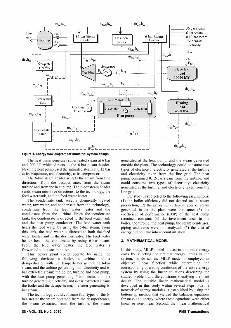
The industrial energy system studied is shown in Figure 1. This energy system consists of a power plant that generates energy and the technology that consumes energy. The power plant consists of a steam boiler, a turbine and a heat pump. The steam boiler generates high pressure steam, the turbine generates electricity and 6-bar extracted steam, whereas the heat pump generates low pressure steam. Steam and electrical energy could also be taken from outside sources. The technology consumes heat and electricity, and the heat pump consumes electricity and low grade steam.
The boiler house consists of a steam boiler, a 36-bar steam header, a desuperheater, a 6-bar steam header, a condensate tank, a feed water tank, a feed water heater, piping and vents utilities. The steam boiler converts fuel to superheated steam at 36 bar and 450 °C and sends it to the 36-bar steam header. This header directs the whole amount of steam either inside the boiler house to the desuperheater or outside the boiler house to the turbine, or at the same time one amount of steam to the desuperheater and other amount of steam to the turbine. In the desuperheater, the steam converts to the superheated steam at 6 bar and 200 °C by mixing steam with feed water and throttling the mixture. The 6-bar steam is subsequently directed to the 6-bar steam header.
The steam turbine uses the 36-bar steam to generate electricity. The turbine extracts superheated steam at 6 bar and 200 °C which is further directed to the 6-bar steam header, in the system with turbine with steam extraction. The steam expansion in the turbine results in the saturated steam at 0.12 bar.
88 ▪ VOL. 38, No 2, 2010 FME Transactions
Figure 1. Energy flow diagram for industrial system design
The heat pump generates superheated steam at 6 bar and 200 °C which directs to the 6-bar steam header. Next, the heat pump used the saturated steam at 0.12 bar at its evaporator, and electricity, at its compressor.
The 6-bar steam header accepts the steam from tree directions: from the desuperheater, from the steam turbine and from the heat pump. The 6-bar steam header sends steam into three directions: to the technology, the feed water tank, and the feed-water heater.
The condensate tank accepts chemically treated water, raw water, and condensate from the technology, condensate from the feed water heater and the condensate from the turbine. From the condensate tank, the condensate is directed to the feed water tank and the heat pump condenser. The feed water tank heats the feed water by using the 6-bar steam. From this tank, the feed water is directed to both the feed water heater and to the desuperheater. The feed water heater heats the condensate by using 6-bar steam. From the feed water heater, the feed water is forwarded to the steam boiler.
This power plant could operate by using the following devices: a boiler, a turbine and a desuperheater, with the desuperheater generating 6-bar steam, and the turbine generating both electricity and 6-bar extracted steam; the boiler, turbine and heat pump, with the heat pump generating 6-bar steam, and the turbine generating electricity and 6-bar extracted steam; the boiler and the desuperheater, the latter generating 6-bar steam.
The technology could consume four types of the 6-bar steam: the steam obtained from the desuperheater, the steam extracted from the turbine, the steam
generated at the heat pump, and the steam generated outside the plant. The technology could consume two types of electricity: electricity generated at the turbine and electricity taken from the line grid. The heat pump consumed 0.12-bar steam from the turbine, and could consume two types of electricity: electricity generated at the turbine, and electricity taken from the line grid.
Our study is subjected to the following assumptions: (1) the boiler efficiency did not depend on its steam production; (2) the prices for different types of steam generated inside the plant were the same; (3) the coefficient of performance (COP) of the heat pump remained constant; (4) the investment costs in the boiler, the turbine, the heat pump, the steam condenser, piping and vents were not analyzed; (5) the cost of energy did not take into account inflation.
3. MATHEMATICAL MODEL
In this study, MILP model is used to minimize energy costs by selecting the optimal energy inputs in the system. To do so, the MILP model is employed an objective linear function while determining the corresponding operating conditions of the entire energy system by using the linear equations describing the studied problem and the constrains specifying the plant design. The suitable linear mathematical model is developed in this study within several steps. First, a network of energy modules is established by using the bottom-up method that yielded the balances equations for mass and energy, where these equations were either linear or non-linear. Second, the linear mathematical
FME Transactions VOL. 38, No 2, 2010 ▪ 89
model is developed by linearization of the non-linear equations. Third, the linear objective function is constructed and finally the constraints governing the system are acknowledged.
3.1 Network of energy modules and equations of the
system
The bottom-up method is used to develop the energy module network for energy system, shown in Figure 1. The used modules were the boiler, 36-bar steam header, desuperheater, 6-bar steam header, steam turbine, generator, cooling tower, heat pump (its evaporator, condenser, expansion valve and compressor), condensate tank, feed water tank, feed water heater, technology power consumer and technology heat consumer. These modules are connected with the flow paths of 36-bar steam, 6-bar steam, 0.12-bar steam, condensate and electricity. Based on this network, mathematical model is derived and presented in Appendix. Mathematical model of system with condensing steam turbine with the extraction are defined with equations (A1 – A3a) – (A4 – A9a) – (A10 – A21a) – (A22 – A24a) – (A25 – A26a), and for the system with condensing steam turbine without the extraction are defined with equations (A1 – A2) – (A3b – A8) – (A9b – A20) – (A21b – A23) – (A24b – A25).
3.2 MILP constraints
This mathematical model had constraints, which specified the plant design:
,min ,max , f 1, g 1, d 1i i im m m≤ ≤ ≤ ≤ ≤ (1)
where mi,min and mi,max are minimum and maximum mass flow rate of the steam at the entrance of the turbine and minimum and maximum amount of saturated steam at the exit of the turbine; f presents proportions the total amount of steam that would be cooled in the cooling tower and that would be cooled in the heat pump; g presents proportions the total amount of turbine electricity which would be consumed by the heat pump and which would be consumed in the technology; d presents proportions the total amount of grid electricity which would be used by the heat pump and which would be used in the technology.
3.3 The objective function
In this paper, the linear objective function is economic in nature and involved cost minimizations. This cost function depended on the amounts of the different energy inputs and their unit costs. The objective is to minimize the operating expenses in the plant that consumes heat and electricity. The heat is obtained from 6-bar steam generated by the factory power plant by using the following devices: desuperheater, Q6d, the condensing steam turbine with the extraction, Q6ex, and its heat pump, Qhp, or produced by outside supplier, Qso. The electricity could be either produced in the boiler house by the turbine or taken from the grid. Electricity
produced by the turbine could be used by the technology, Etl, and by the heat pump, Ethp. The electricity purchased from the line grid also could be used by the technology, Egl, and by the heat pump, Eghp. The objective function is then stated as:
( )6 6d 6ex so soF C Q Q C Q= + + +
( ) ( )t tl thp g gl ghpC E E C E E+ + + + . (2)
In this research, it was taken that heat generated by the heat pump was free of charge and all costs incurred by the heat pump operation are included in the costs for electricity that the heat pump used during its operation. The unit cost for grid electric was Cg = 0.25 €/kWh, and the unit cost for heat generated by steam from external source was Cso = 0.1 €/kWh.
3.4 Optimization procedure
The energy costs are optimized i.e. minimized in an iteration procedure by using the previously developed equalities and inequalities and the system physical and operational parameters. The relationships given in Appendix may contain nonlinear terms such as m · h, where m represents an unknown mass flow rate, and h an unknown enthalpy. The constraint relationships must be linear because the simplex algorithm, used by the LP solution codes, cannot handle nonlinear terms. To get around this problem, it is possible to replace the nonlinear terms with single variables, or with linear approximations, in order to form a linear model. The approximations require estimates of coefficients. When the estimates are correct, the errors introduced by the approximations become insignificant. In this investigation iterative estimation of coefficients is used, and subsequent problem solution, until a stable set of coefficients is found that satisfies maximum error requirements. The LP solution that utilizes this last set of coefficients is the solution we are seeking.
In most cases, the nonlinear product m · h must be replaced by a first-order Taylorseries expansion:
c c c cm h m h m h m h⋅ ≈ ⋅ + ⋅ − ⋅ (3)
where mc and hc are Taylor expansion coefficients, and are the best available estimates of the true values of m and h. Values for these coefficients must be estimates initially, and then reevaluated by successive LP solutions until a tolerance test can be met.
4. RESULTS
The results of optimization are given through different scenarios of energy use, by using energy-mix regions. Each energy-mix region presents combinations of C6 and Ct, which requires a specific energy mix to be used by the load, giving the lowest costs for energy. For each particular energy-mix region optimum mix of heat and electricity inputs for the system with the condensing steam turbine with the extraction are given in Figure 2, and for the system with the condensing steam turbine without the extraction in Figure 3.

90 ▪ VOL. 38, No 2, 2010 FME Transactions
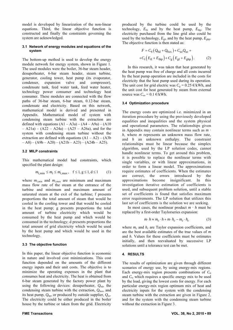
Figure 2. Optimal consumption by the system with the condensing steam turbine with the extraction (10 MW heat load, 4.5 MW electrical load)
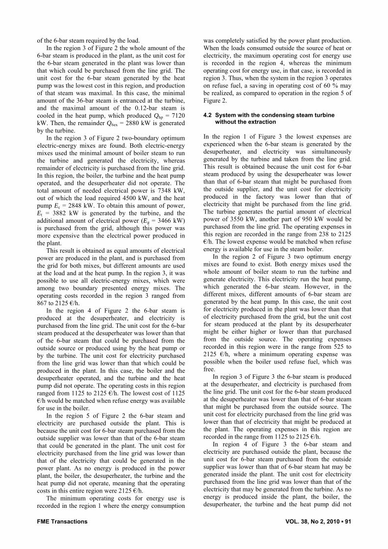
Figure 3. Optimal consumption by the system with condensing steam turbine without extraction (10 MW heat load, 4.5 MW electrical load)
4.1 System with the condensing steam turbine with
the extraction
In the region 1 of Figure 2 the lowest cost is experienced when the turbine simultaneously generated the 6-bar steam heat and electricity. This result is obtained as the unit cost for 6-bar steam heat produced by using the turbine was lower than that of 6-bar steam that could be purchased from the outside supplier or produced by using the desuperheater or heat pump. In addition, the unit cost for electricity produced in the plant was lower than that of electricity that could be purchased from the line grid. The operating costs in this region are recorded up to 2125 €/h. The lowest cost 0 €/h would be matched when refuse energy (free fuel) was available to be used in the plant boiler.
In the region 2 of Figure 2 the electricity and the 6-bar steam heat is produced in the plant. Figure 2 shows that Q6ex = 8250 kW is the power produced by an extraction turbine, Qh = 1750 kW is generated by the heat pump, and Et = 5200 kW is used in the plant, where 4500 kW and 700 kW stand for the technology and the heat pump respectively. As the COP of the heat pump was 2.5, the heat pump produced Qhp = 1750 kW. The result is obtained as the unit cost of electricity produced in the plant was lower than that which could be purchased from the line grid. In the region 2 the unit cost for the 6-bar steam generated by using the heat pump was lower than that for 6-bar steam generated by the turbine and by the desuperheater or could be purchased from the outside supplier. In this region the turbine and the heat pump operated altogether, and simultaneously produced the whole amount of needed
FME Transactions VOL. 38, No 2, 2010 ▪ 91
of the 6-bar steam required by the load. In the region 3 of Figure 2 the whole amount of the
6-bar steam is produced in the plant, as the unit cost for the 6-bar steam generated in the plant was lower than that which could be purchased from the line grid. The unit cost for the 6-bar steam generated by the heat pump was the lowest cost in this region, and production of that steam was maximal. In this case, the minimal amount of the 36-bar steam is entranced at the turbine, and the maximal amount of the 0.12-bar steam is cooled in the heat pump, which produced Qhp = 7120 kW. Then, the remainder Q6ex = 2880 kW is generated by the turbine.
In the region 3 of Figure 2 two-boundary optimum electric-energy mixes are found. Both electric-energy mixes used the minimal amount of boiler steam to run the turbine and generated the electricity, whereas remainder of electricity is purchased from the line grid. In this region, the boiler, the turbine and the heat pump operated, and the desuperheater did not operate. The total amount of needed electrical power is 7348 kW, out of which the load required 4500 kW, and the heat pump Ec = 2848 kW. To obtain this amount of power, Et = 3882 kW is generated by the turbine, and the additional amount of electrical power (Eg = 3466 kW) is purchased from the grid, although this power was more expensive than the electrical power produced in the plant.
This result is obtained as equal amounts of electrical power are produced in the plant, and is purchased from the grid for both mixes, but different amounts are used at the load and at the heat pump. In the region 3, it was possible to use all electric-energy mixes, which were among two boundary presented energy mixes. The operating costs recorded in the region 3 ranged from 867 to 2125 €/h.
In the region 4 of Figure 2 the 6-bar steam is produced at the desuperheater, and electricity is purchased from the line grid. The unit cost for the 6-bar steam produced at the desuperheater was lower than that of the 6-bar steam that could be purchased from the outside source or produced using by the heat pump or by the turbine. The unit cost for electricity purchased from the line grid was lower than that which could be produced in the plant. In this case, the boiler and the desuperheater operated, and the turbine and the heat pump did not operate. The operating costs in this region ranged from 1125 to 2125 €/h. The lowest cost of 1125 €/h would be matched when refuse energy was available for use in the boiler.
In the region 5 of Figure 2 the 6-bar steam and electricity are purchased outside the plant. This is because the unit cost for 6-bar steam purchased from the outside supplier was lower than that of the 6-bar steam that could be generated in the plant. The unit cost for electricity purchased from the line grid was lower than that of the electricity that could be generated in the power plant. As no energy is produced in the power plant, the boiler, the desuperheater, the turbine and the heat pump did not operate, meaning that the operating costs in this entire region were 2125 €/h.
The minimum operating costs for energy use is recorded in the region 1 where the energy consumption
was completely satisfied by the power plant production. When the loads consumed outside the source of heat or electricity, the maximum operating cost for energy use is recorded in the region 4, whereas the minimum operating cost for energy use, in that case, is recorded in region 3. Thus, when the system in the region 3 operates on refuse fuel, a saving in operating cost of 60 % may be realized, as compared to operation in the region 5 of Figure 2.
4.2 System with the condensing steam turbine
without the extraction
In the region 1 of Figure 3 the lowest expenses are experienced when the 6-bar steam is generated by the desuperheater, and electricity was simultaneously generated by the turbine and taken from the line grid. This result is obtained because the unit cost for 6-bar steam produced by using the desuperheater was lower than that of 6-bar steam that might be purchased from the outside supplier, and the unit cost for electricity produced in the factory was lower than that of electricity that might be purchased from the line grid. The turbine generates the partial amount of electrical power of 3550 kW, another part of 950 kW would be purchased from the line grid. The operating expenses in this region are recorded in the range from 238 to 2125 €/h. The lowest expense would be matched when refuse energy is available for use in the steam boiler.
In the region 2 of Figure 3 two optimum energy mixes are found to exist. Both energy mixes used the whole amount of boiler steam to run the turbine and generate electricity. This electricity run the heat pump, which generated the 6-bar steam. However, in the different mixes, different amounts of 6-bar steam are generated by the heat pump. In this case, the unit cost for electricity produced in the plant was lower than that of electricity purchased from the grid, but the unit cost for steam produced at the plant by its desuperheater might be either higher or lower than that purchased from the outside source. The operating expenses recorded in this region were in the range from 525 to 2125 €/h, where a minimum operating expense was possible when the boiler used refuse fuel, which was free.
In region 3 of Figure 3 the 6-bar steam is produced at the desuperheater, and electricity is purchased from the line grid. The unit cost for the 6-bar steam produced at the desuperheater was lower than that of 6-bar steam that might be purchased from the outside source. The unit cost for electricity purchased from the line grid was lower than that of electricity that might be produced at the plant. The operating expenses in this region are recorded in the range from 1125 to 2125 €/h.
In region 4 of Figure 3 the 6-bar steam and electricity are purchased outside the plant, because the unit cost for 6-bar steam purchased from the outside supplier was lower than that of 6-bar steam hat may be generated inside the plant. The unit cost for electricity purchased from the line grid was lower than that of the electricity that may be generated from the turbine. As no energy is produced inside the plant, the boiler, the desuperheater, the turbine and the heat pump did not

92 ▪ VOL. 38, No 2, 2010 FME Transactions
operate. The operating expenses in this entire region were 2125 €/h.
The maximum operating expense for energy use is recorded in region 4 and the minimum operating expense for energy use is recorded in region 1 of Figure 3. Thus, when the system in region 1 can be operated on refuse fuel, a saving in operating expense of 88.8 % may be realized, as compared to operation in region 4.
Summary of the minimum energy operating expenses for each energy-mix region for analyzed systems, depending on the costs of the internal energy inputs, are given in Table 1. Table 1. Summary of costs
Region Costs of energy usage for the system with the condensing steam turbine [€/h]
with the extraction without the extraction
1 10000 · C6 + 4500 · Ct 10000 · C6 + 3550 · Ct +
238 2 8250 · C6 + 5200 · Ct 6400 · Ct + 525 3 2880 · C6 + 3882 · Ct + 867 10000 · C6 + 1125 4 10000 · C6 + 1125 2125 5 2125 –
5. CONCLUSION
In this paper, a linear programming model of the industrial energy system is developed to determine the optimal strategies that minimize the energy cost of the system. It is shown that there are optimal energy-mix regions of the system. When applying this method, the saving in energy costs up to 60 % may be obtained for the system with the condensing steam turbine with the extraction, and up to 88 % for the system with the condensing steam turbine without the extraction, depending on the costs of energy inputs. It is pointed out that this method can be used for energy systems of other industrial power plants with similar configurations.
APPENDIX
The system equations – mass balances (mark “a” refers to the system with the condensing steam turbine with the extraction; mark “b” refers to the system with the condensing steam turbine without the extraction):
b 36t 36db km m m= + , (A1)
36d f3d 6dk km m m+ = , (A2)
6d 6ex hp 6f 3 6f 4 6skm m m m m m+ + = + + , (A3a)
6d hp 6f 3 6f 4 6skm m m m m+ = + + , (A3b)
36t 6ex 0sb bm m m= + , (A4)
f1 1cr 0s 6f 4 f 2f hpbm m m m m m+ + + = + , (A5)
f 2f 6f 3 f 3d bm m m m+ = + , (A6)
6s 1cr 1clm m m= + . (A7)
The system equations – energy balances:
36d 36 f 3d f 3 6d 6k km h m h m h+ = , (A8)
36t 36 6ex 6 0s 0.12 tb bm h m h m h E− − = , (A9a)
36t 36 0s 0.12 tb bm h m h E− = , (A9b)
0s 0.12 0c ctb ( )m h h Q− = , (A10)
hpe ctfQ Q= , (A11)
f1 f1 1cr 1c 0s 0c 6f 4 1cbm h m h m h m h+ + + = f 2f f 2 hp f 2m h m h= + , (A12)
f 2f f 2 6f 3 6 b f 3 f 3d f 3m h m h m h m h+ = + , (A13)
( ) ( )6f 4 6 1c b f 3 f 4m h h m h h− = − , (A14)
( )hpc hp 6 f 2Q m h h= − , (A15)
hpc c hpeQ E Q= + , (A16)
hpc cCOPQ E= ⋅ , (A17)
c tc mcg dE E E= + , (A18)
t tt tcgE E E= + , (A19)
m mt mcdE E E= + , (A20)
( )( )6d 6s hp 6ex 6 1cQ m m m h h= − − − , (A21a)
( )( )6d 6s hp 6 1cQ m m h h= − − , (A21b)
hp hp 6 1c( )Q m h h= − , (A22)
so so 6 1c( )Q m h h= − , (A23)
ft so 6d hp 6exQ Q Q Q Q= + + + , (A24a)
ft so 6d hpQ Q Q Q= + + , (A24b)
ft mt ttE E E= + , (A25)
6ex 6ex 6 1c( )Q m h h= − . (A26a)
REFERENCES
[1] Alardhi, M. and Labib, A.W.: Preventive maintenance scheduling of multi-cogeneration plants using integer programming, Journal of the Operational Research Society, Vol. 59, No. 4, pp. 503-509, 2008.
[2] Kong, X.Q., Wang, R.Z. and Huang, X.H.: Energy optimization model for a CCHP system with available gas turbines, Applied Thermal Engineering, Vol. 25, No. 2-3, pp. 377-391, 2005.
[3] Arivalagan, A., Raghavendra, B.G. and Rao, A.R.K.: Integrated energy optimization model for a cogeneration based energy supply system in the process industry, International Journal of Electrical Power & Energy Systems, Vol. 17, No. 4, pp. 227-233, 1995.

FME Transactions VOL. 38, No 2, 2010 ▪ 93
[4] Kramer, R.A.: Optimized combined heat and power energy applications and renewables, in: Proceedings of the 2nd International Energy Conversion Engineering Conference, 16-19.08.2004, Providence, USA, Paper AIAA 2004-5742.
[5] Bojić, M. and Dragićević, S.: Optimization of steam boiler design, Proceedings of the Institution of Mechanical Engineers, Part A: Journal of Power and Energy, Vol. 220, No. 6, pp. 629-634, 2006.
[6] Yokohama, R. and Ito, K.: A novel decomposition method for MILP and its application to optimal operation of a thermal storage system, Energy Conversion and Management, Vol. 41, No. 16, pp. 1781-1795, 2000.
[7] Georgiadis, M.C., Papageorgiou, L.G. and Macchietto, S.: Optimal cleaning policies in heat exchanger networks under rapid fouling, Industrial & Engineering Chemistry Research, Vol. 39, No. 2, pp. 441-454, 2000.
[8] Rong, A. and Lahdelma, R.: An efficient linear programming model and optimization algorithm for trigeneration, Applied Energy, Vol. 82, No. 1, pp. 40-63, 2005.
[9] Dragićević, S. and Bojić, M.: An energy optimization model for a combined heat and power production energy supply system with a heat pump, Proceedings of the Institution of Mechanical Engineers, Part A: Journal of Power and Energy, Vol. 223, No. 4, pp. 321-328, 2009.
NOMENCLATURE
b binary variable that controls operation of the desuperheater
C unit cost [€/kWh] COP coefficient of performance
d continuous variable that controls the use of main electricity by the heat pump and the technology
E power [kW]
f continuous variable that controls the use of cooling tower and the heat pump evaporator to condense the 0.12-bar steam
g continuous variable that controls the use of generator electricity by the technology and the heat pump
h specific enthalpy [kJ/kg]
k binary variable that controls operation of the turbine
m mass flow rate [kg/s] Q heat [kW]
Subscripts
0c 0.12-bar condensate 0s 0.12-bar steam produced by the turbine 0.12 0.12-bar steam 1c 1-bar condensate 1cl condensate losses
1cr condensate from the technology to the condensate tank
6 6-bar steam
6ex 6-bar extracted steam
6s entering the technology from the 6-bar steam header
6f3 entering the feed water tank from the 6-bar steam header
6f4 entering the feed water heater from the 6-bar steam header
6d entering the 6-bar steam header from the desuperheater
36 36-bar steam 36t 36-bar steam entering the turbine 36d 36-bar steam entering the desuperheater b steam produced by the boiler c electricity used by the heat pump ct cooling tower and the heat pump evaporator f1 raw water entering the condensate tank f2 feed water in the condensate tank
f2f entering the feed water tank from the condensate tank
f3 feed water in the feed water tank
f3d entering the desuperheater from the feed water tank
f4 feed water in the heater ft factory technology hp steam produced by the heat pump
hpc heat generated by the heat pump at its condenser
hpe heat received by the heat pump at its evaporator
m electricity from the main
mc electricity from the main used by the heat pump
mt electricity form the main used by the technology
so 6-bar steam form the outside supplier t electricity produced by the turbine
tt electricity produced by the turbine and used by technology
tc electricity produced by turbine and used by the heat pump
ОПТИМИЗАЦИЈА ИНДУСТРИЈСКИХ
ЕНЕРГЕТСКИХ СИСТЕМА
Снежана М. Драгићевић, Милорад Љ. Бојић За задовољавање потреба за топлотном и електричном енергијом индустријски системи троше топлотну и електричну енергију, које се могу производити унутар система или се троше из спољашњих извора енергије. Основни елементи анализираног индустријског система су парни котао, турбина и топлотна пумпа. Коришћењем методе линеарног програмирања креиран је модел помоћу кога се одређује режим рада система код кога је оптимална потрошња топлотне и електричне енергије, при чему су трошкови коришћења енергије минимални. Оптимална потрошња енергије дата је дијаграмски за два типа система који се разликују по врсти турбине. Резултати оптимизације показују да је могуће остварити

94 ▪ VOL. 38, No 2, 2010 FME Transactions
смањење трошкова коришћења енергије до 88 % код система са кондензационом турбином, односно
до 60 % код система са турбином са одузимањем водене паре.