optimization of manufacturing conditions for · pdf fileoptimization of manufacturing...
TRANSCRIPT
OPTIMIZATION OF MANUFACTURING CONDITIONS FOR SPLINE OF DRUM CLUTCH HUB TAGUCHI METHOD
Joon-Hong Park1, Seung-Gyu Kim2, Seung-Kul Baek2, and Young-Chul Park3*
1 CANSMC, Dong-A University, Busan, Korea
2 School of Mechanical Engineering, Dong-A University, Busan, Korea 3 Department of Mechanical Engineering, Dong-A University, Busan, Korea
* Corresponding author ([email protected])
ABSTRACT: A large variety of metal forming processes is required in manufacturing for automotive applications.
Traditionally the design process for metal forming tools is based on trial-and-error and on the skill of experienced die-
makers. This approach results in high development cost and long lead-times. Especially spline of drum clutch hub requires
tight dimensional accuracy in its inside diameter and gear shape because it is used as the main component for the automatic
transmission. In this paper, the most desirable or feasible manufacturing conditions for spline of drum clutch hub were
found or determined by using Taguchi method and FE-simulation(FORGE-3D). Taguchi's optimization approach was used
to obtain the optimal parameters. The significant parameters were identified and their effects on Manufacturing of spline
were studied. As a results, a confirmation experiment with the optimal levels of manufacturing parameters was carried out
in order to demonstrate the effectiveness of the Taguch method.
Keywords: FE-Simulation, Drum Clutch Hub, Spline, Manufacturing Conditions, Design of Experiment, Taguchi Method
1. INTRODUCTION
At present, most of the automobile components responsible
for providing rotatory motion, such as gears and clutches,
are produced through such cutting processes as hobbing,
shaping, and shaving under the demand that they be highly
precise, highly robust, and highly durable. However,
research on component forming depending on plasticity
processing methods such as drawing, extruding, and
forging is being actively conducted in order to do away
with the simplicity of processing methods that rely
primarily on cutting processes, for the purpose of
increasing the productivity of these components.
Plastic working has the advantages of bringing about high
productivity, low rates of material consumption, low costs
of production per product, and a high quality of the
products themselves. A number of developments of higher
value-added plasticity processing techniques have been
made recently in order to meet the demands for higher
competitive power of the products. Among those
techniques, the deep-drawing processing method used in
the forming of cylindrical containers that make use of thin
plates whose surface area is infinitely larger than their
thickness is difficult to implement particularly with regard
to measurement precision and forming load. Technical
developments are being made through various forms of
research that utilize FEM(Finite Element Method) and a
number of experiments based on basic theories on this
topic.
The automobile drum clutch hub, for which this research
focuses on developing the preform, is a main component
that directly affects torque transmission needed for
automobile movement and that is directly related to the
overall quality of automobile performance. Products have
been manufactured based on the recommendation for a
new preliminary forming process required for developing
precise products demanded by the automotive industry
with respect to the preforms of drum clutch hubs that are
manufactured in progressive dies.
These products are expected to increase the degree of
precision in the manufacture of drum clutch hubs by
P2-23
1472
solving the corner filling problem that has been regarded
the most difficult to solve in existing deep-drawing
processes. Moreover, they are expected to be applied to
other deep-drawing processes to manufacture highly
precise deep-drawing products.
2. DRUM CLUTCH HUBS FOR TRANSMISSION
The drum clutch hub, one of the key components in
automobile transmission, is directly linked to the efficiency
of power transmission and to the level of vibration noises.
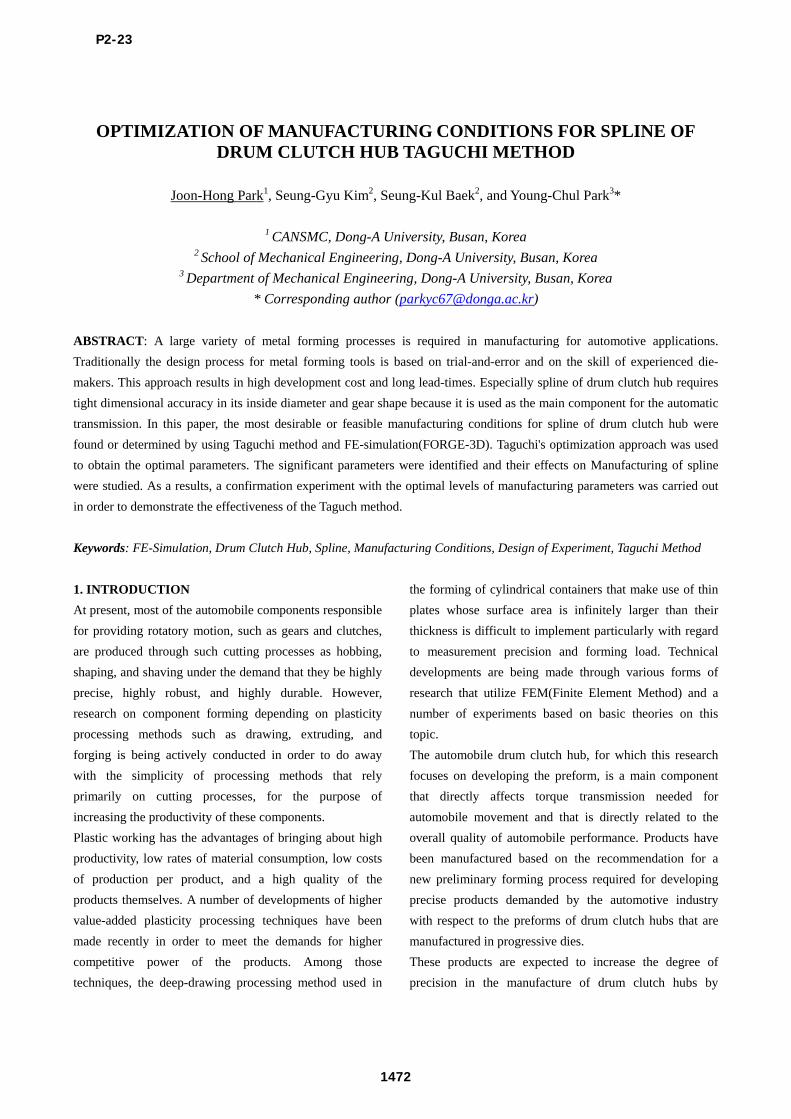
Figure 1 below illustrates a planet carrier with drum clutch
hub products, the red dotted lines outlining the final drum
clutch hub products. The manufacture of drum clutch hub
products consists of importing all needed raw materials
from Japan, using these materials to design preform
through progressive forming processes, and finally
producing the teeth of hub through Grob, Inc. cutting
processes. The Grob, Inc. forming process is a cold
rotational forming process that is used in the forming of a
variety of products, including spline shafts, section steel,
various kinds of gear products, pulley products, and the
tubes of heat exchangers. Figure 2 below illustrates an
example of the GrobTM forming process with a roll.
Research results on the analysis and the optimal design of
the GrobTM forming process for the manufacture of drum
clutch hub products will be provided in a later research
paper.
Kim et al. attempted a composite forming process through
control metal flow and examined the minimization of
material loss as a result of product manufacture and
number of process decrease and the feasibility of a cutting-
free process with the use of Rigid Plastic FEM to present
the optimal forming process depending on the effects of
process variables. Hussain et al. analyzed the forming
process of drum clutch hubs using CAMPformTM and
proposed the conditions needed for manufacturing high-
quality products.
In recent research, Kim et al. proposed a new press
forming process that can replace the GrobTM forming
process. It may be possible for the new process to replace
the GrobTM forming process in the areas of the approach
angles from punch, the analysis based on operation
methods in GrobTM forming, and a variety of ironing
processes for GrobTM forming. However, the application of
the progressive process to the manufacture of clutch hub
products results in firstly, the increase in press capacity due
to excessive forming load secondly, a significant rise in the
number of processes with respect to certain products,
depending on the shapes of those products. In particular,
deep-drawing and ironing processes used in the forming of
preforms are by themselves unable to bring about sufficient
thickness in corner round. Thus, this research paper will
propose a new shape for preforms to address this problem.
Fig. 1 Photograph of drum clutch hub products for
automobile transmission
Fig. 2 An example of GrobTM forming process for spur
gears
3.DEEP-DRAWING PROCESS
Drum clutch hub products are to be highly precise, highly
robust, and highly durable. Changes in the thickness and
the distribution of the wall surfaces and the floor surfaces
P2-23
1473

of preforms whose shapes are drum-like are particularly
noteworthy as they directly affect the defect in the second
process, namely teeth of hub manufacture. Therefore, they
are directly responsible for the qualities of the products.
Much research has been conducted on the thickness
distribution of products, since it is the most considerable
matter of concern also in the thin-plate deep-drawing
process. Among a number of research papers, those by
Romanowki and Sellin have shown that the effects the
shapes of corner of the die have on the distribution of and
changes in thickness are the greatest.
4.FE-SIMULATION
DEFORM-2DTM, which is a FEM code, was used in
conducting a FE simulation in this research, and conditions
for analysis are provided in Table 1. One of the materials
used in the manufacture of clutch drum hub preform is
SAPH 3.0t, which is a key material in the production of
automobile clutch components. Table 2 lists the mechanical
properties of SAPH 3.0t. The following equation has been
obtained from the experiment data provided in Table 2,
using the flow stress curve and curve fitting.
Table 1: Condition for FE-simulation
Conditions Type
Material of workpiece SAPH
Punch speed 1.0mm/s
Friction 0.1
Table 2: Tensile test result of SAPH
Properties Experiment data
Yield Strength 290MPa
Tensile Strength 493MPa
Young’s Modulus 40.011GPa
Elongation 39%
5.FORMING PROCESS
The forming of clutch drum hub preform is carried out in
two steps taking various conditions into consideration, as
shown in Figure 3 This research paper proposes the
reverse-drawing method in which the location and the role
of the punch and the die are reversed in the general deep-
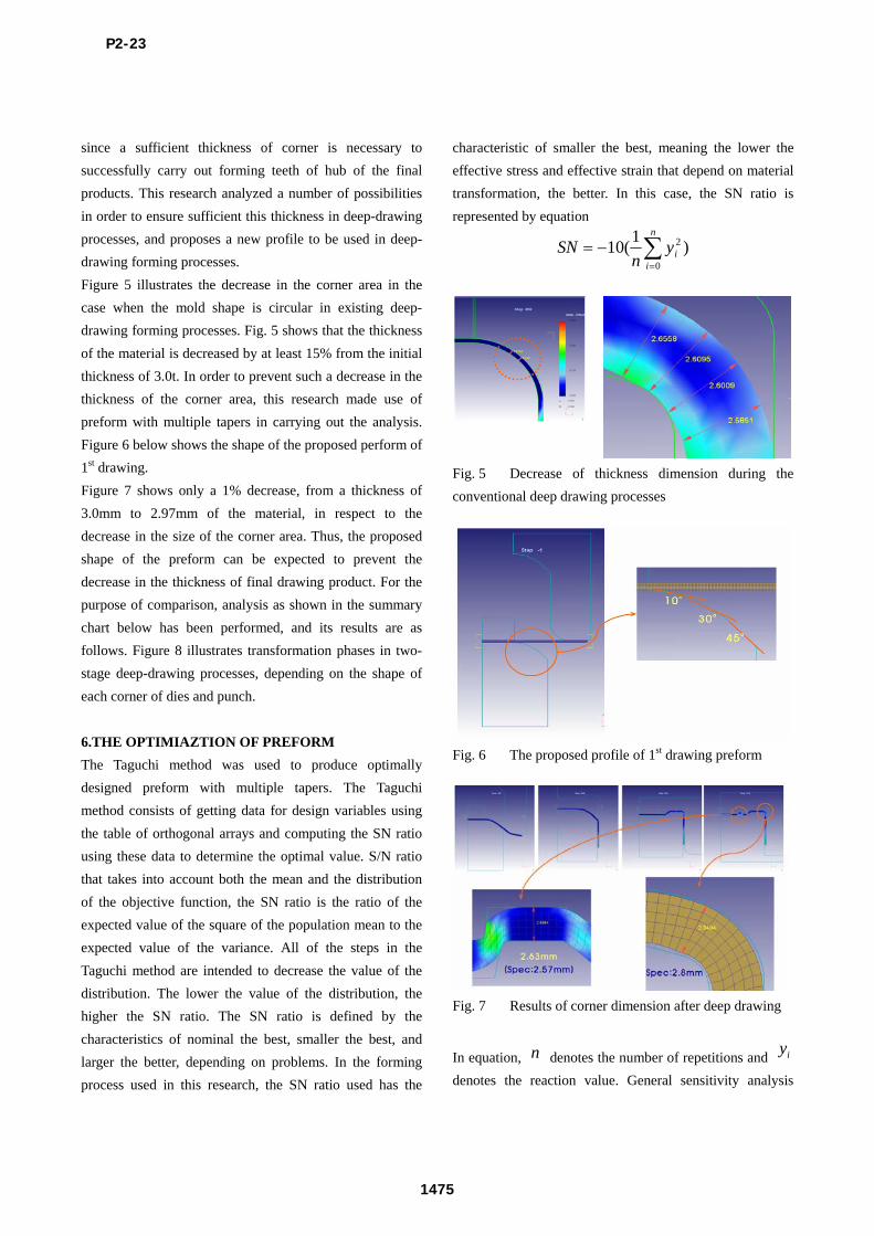
drawing process. The shape of the corner of the punch and
the die was selected as the process variable, as it affects the
degree of measurement precision, the forming load, and the
resistance to transformation the most in the first stage of
the deep-drawing process. As shown in Figure 4, the
shapes of the corner shape of dies and punch consist of the
shape with a taper (a), the shape with a round (b), and the
punch shape resulting from three types of dies with a
separate taper. Depending on the shape, two steps of
forming analysis in the deep-drawing process were carried
out
Fig. 3 Process of Deep-drawing the drum hub preform
Fig. 4 Various shapes of corner of die for 1st deep
drawing process
The decrease in thickness of drawing product is generally
accepted to be a natural result of the execution of the
drawing process. However, in the case of drum clutch hub
products, designing the shape of the preform for the
purpose of increasing the thickness of corner is crucial,
P2-23
1474
since a sufficient thickness of corner is necessary to
successfully carry out forming teeth of hub of the final
products. This research analyzed a number of possibilities
in order to ensure sufficient this thickness in deep-drawing
processes, and proposes a new profile to be used in deep-
drawing forming processes.
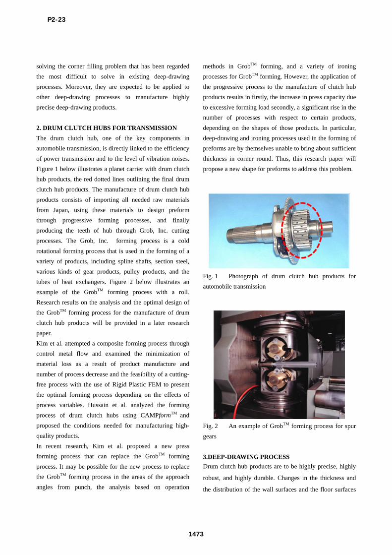
Figure 5 illustrates the decrease in the corner area in the
case when the mold shape is circular in existing deep-
drawing forming processes. Fig. 5 shows that the thickness
of the material is decreased by at least 15% from the initial
thickness of 3.0t. In order to prevent such a decrease in the
thickness of the corner area, this research made use of
preform with multiple tapers in carrying out the analysis.
Figure 6 below shows the shape of the proposed perform of
1st drawing.
Figure 7 shows only a 1% decrease, from a thickness of
3.0mm to 2.97mm of the material, in respect to the
decrease in the size of the corner area. Thus, the proposed
shape of the preform can be expected to prevent the
decrease in the thickness of final drawing product. For the
purpose of comparison, analysis as shown in the summary
chart below has been performed, and its results are as
follows. Figure 8 illustrates transformation phases in two-
stage deep-drawing processes, depending on the shape of
each corner of dies and punch.
6.THE OPTIMIAZTION OF PREFORM
The Taguchi method was used to produce optimally
designed preform with multiple tapers. The Taguchi
method consists of getting data for design variables using
the table of orthogonal arrays and computing the SN ratio
using these data to determine the optimal value. S/N ratio
that takes into account both the mean and the distribution
of the objective function, the SN ratio is the ratio of the
expected value of the square of the population mean to the
expected value of the variance. All of the steps in the
Taguchi method are intended to decrease the value of the
distribution. The lower the value of the distribution, the
higher the SN ratio. The SN ratio is defined by the
characteristics of nominal the best, smaller the best, and
larger the better, depending on problems. In the forming
process used in this research, the SN ratio used has the
characteristic of smaller the best, meaning the lower the
effective stress and effective strain that depend on material
transformation, the better. In this case, the SN ratio is
represented by equation
n
iiy
nSN
0
2 )1
(10
Fig. 5 Decrease of thickness dimension during the
conventional deep drawing processes
Fig. 6 The proposed profile of 1st drawing preform
Fig. 7 Results of corner dimension after deep drawing
In equation, n denotes the number of repetitions and iy
denotes the reaction value. General sensitivity analysis
P2-23
1475

makes use of the analysis of variance on SN ratios to
evaluate the considerable effects design variables have on
SN ratios. The reproducibility of the optimal level is
evaluated in comparison with what is expected to be the
optimal value, obtained from a confirming experiment.
Experiment conditions are then standardized.
This research replaced the preliminary experiment with the
FE simulation and took into account the 5 process variables,
namely R1, R2, θ1,θ2, and θ3 in table of orthogonal
arrays L16. Table 3 lists the 5 process variables and shows
the 4 levels used in this research. Table 4 provides the
experiment results of L16
Table 3: Process parameters and their levels
Process
Parameter Description Level 1 Level 2 Level 3 Level 4
X1 R1 35 40 45 50
X2 R2 30 40 45 50
X3 θ1 10 13 16 19
X4 θ2 18 22 26 30
X5 θ3 70 60 50 40
Table 4: Result of L16 array with observational data
No. Max. Stress Max. Strain
1 469.2 0.7034
2 468.7 0.7002
3 470.2 0.6998
4 465.3 0.6847
5 468.5 0.6985
6 465.8 0.6842
7 461.2 0.7021
8 472.3 0.7023
9 471.2 0.7033
10 472.6 0.7029
11 466.5 0.7054
12 468.1 0.7014
13 467.3 0.6984
14 462.3 0.6984
15 469.3 0.6996
16 470.7 0.7015
Fig. 8 Main effect plot for maximum stress
Fig. 9 Main effect plot for maximum stress
Figure 8 and Figure 9 show the main effects of SN ratios
on the 5 key process variables. Evaluation of the main
effects is not intended to determine an exact causal
relationship by comparing with the results from the
variance analysis, but to separate the incoming effect from
the other effects of the reaction value in order to use the
ratio of the former and latter effects in design evaluation.
Overall, the characteristics of each reaction value get better
as the size and level of the sensitivity of process variables
decrease to Round Radius R1(X1) and Multi taper angle
3(X5) and increase to Round Radius R2(X2) and Multi
taper angle 1(X3), Multi taper angle 2(X4). Thus, it can be
seen that the maximum stress and the maximum strain of
final product decrease when Round Radius R1(X1) , Multi
taper angle 3(X5) is decreased and Round Radius R2(X2)
and Multi taper angle 1(X3), Multi taper angle 2(X4) is
increased.
The process variables that have the most significant effects
on hub forming and Multi taper angle 2(X4). The mean SN
ratio is 2.9957 and the reaction value is 0.628, and the
P2-23
1476

optimal conditions of the process variables are R1=35,
R2=50, θ1=19, θ2=30, θ3=70.
7. DRAWING TEST
In the shape optimization process applying the Taguchi
method, it is best to select the shape shown in Figure 11 as
the shape of the preform in the forming of hub products.
Fig. 10 Shape of optimal 1st drawing punch and die
Based on this process design, a mold has been made and
preforms identical to that in figure. Figure 11 illustrates
cross sections of the product, and compares the sizes of
“A”~“H” with actual results. Table 5 shows the results of
the analysis of the thickness of each part in Fig. 12 and the
results of the measurement of products. The result was
satisfactory, with an error range of + - 3.5%.
8. CONCLUSION
This research proposed a new preform shape that enables
the prevention of the decrease in corner-area measurements
during the 2-stage deep-drawing process of automobile
clutch drum hub performs. In addition, this research
focused on the effects the resulting molds, namely the
shape of coner of the lower die and the upper punch,
have on the thickness of the corner area of the product. The
results of the process design were then taken into
consideration to produce molds and carry out experiments
for the manufacture of products and succeeded in making
products of high quality. The conclusions from this
research are as follows.
Fig. 11 Section view of hub perform and location of
dimension measurement
Table 5: Comparison of thickness measurement between
FE simulation and test product
Result of FE
simulation Result of Testing DIFF
A 2.8530 2.95 +0.0970
B 2.8517 2.99 +0.1383
C 2.8546 2.80 -0.0546
D 2.8869 2.86 -0.0269
E 3.2.125 3.10 -0.1125
F 2.7365 2.78 0.0435
G 3.0213 3.00 -0.0213
H 3.1210 3.02 -0.1010
ACKNOWLEDGEMENTS
This work was supported by grant No.RT104-01-03 from
the Regional Technology Innovation Program of the
Ministry of Knowledge Economy(MKE)
REFERENCES
[1] Park, J. N., Kim, D. H. and Kim, B. M.,
“Experimental Investigation on the Flow Control of Hub
Clutch for Automobile”, Transaction of Materials
Processing, Vol. 11, No. 5, pp. 430-438, 2002.
[2] Hussain, P. B., Cheon, J. S., Kwak, K. Y., Kim, S. Y.
and Im, Y. T., “Simulation of Clutch-hub Forging Process
using CAMPform,” Journal of Materials Processing
Technology, Vol. 123, pp. 120-132, 2002.
[3] Yokoayma, Y. and Taguchi, G., “Business data
Analysis: Experimental Regression Analysis,” Maruzen,
1975
P2-23
1477