optimization of passenger individual air nozzles · optimization of passenger individual air...
TRANSCRIPT

Optimization of passenger individual air nozzles
March 2017Optimization of passenger individual air nozzles
STAR Global Conference 2017
Andreas RUCH
Environmental Control Systems Airbus Operations GmbH

© AIRBUS Operations GmbH. All rights reserved. Confidential and proprietary document.
Content
March 2017Optimization of passenger individual air nozzles
• Introduction
• Problem description: Purpose of individual air outlets, requirements and
motivation for optimization
• Parametric model creation and setup of automated optimization
• Results: Baseline design, automated design optimization and optimum
solution found
• Summary & Conclusion

© AIRBUS Operations GmbH. All rights reserved. Confidential and proprietary document.
Introduction – Airbus Commercial Aircraft at a glance
March 2017Optimization of passenger individual air nozzles
55,000Employees
€45.8billionAnnual revenue*
10yrsBacklog
400Operators
Data to end 2015
Passion
-Our global workforce is
united by a passion for
aviation and restless
desire to create better
ways to fly

© AIRBUS Operations GmbH. All rights reserved. Confidential and proprietary document.
Introduction – Airbus Commercial Aircraft at a glance
March 2017Optimization of passenger individual air nozzles

© AIRBUS Operations GmbH. All rights reserved. Confidential and proprietary document.
Introduction – Where we use CFD in Environmental Control Systems Design
March 2017Optimization of passenger individual air nozzles

© AIRBUS Operations GmbH. All rights reserved. Confidential and proprietary document.
Individual air nozzles – Purpose
March 2017Optimization of passenger individual air nozzles
• Individual air outlets can be found in many
aircraft models flying today
• Many different variants are existing
• Main reason given for use of nozzle:
• Reduction of ‚stuffiness‘ of air
• After boarding (first 30min) 70% of occupants open
nozzle (higher metabolism, entering from outside)
• Use of nozzles reduces to 62% after 40min, then
constant
• Most occupants target nozzle to upper body part
(52%), 32% to lower body, 15% to head
(head is a very sensitive area; upper body matters
most for overall thermal sensation)
(Source: “Experimental investigation of personal air supply nozzle use in
aircraft cabins”; Zhaosong Fang, Baizhan Li, Andrew N. Baldwin; 2015)

© AIRBUS Operations GmbH. All rights reserved. Confidential and proprietary document.
Individual air nozzles – Purpose
→ With ambient temperatures of >27°C, average velocities of 0.8 m/s
are perceived as comfortable
→ Air velocity is an important factor
March 2017Optimization of passenger individual air nozzles
Source: Ceiling Fans as Extenders of the
Summer Comfort Envelope; F.H. Rohles, F.H.,
S.A. Konz, B.W. Jones; 1983;
Source: ANSI/ASHRAE Standard 55-2013

© AIRBUS Operations GmbH. All rights reserved. Confidential and proprietary document.
Individual air nozzles – Motivation for design improvements
• Amount of air that can be supplied to the individual air nozzles is limited by
the overall air system performance
• Maximum pressure loss of the individual air nozzles is also limited:
• Pressure in supply manifold is driven by overall air system performance
• Generally, less pressure loss also means less noise generation
March 2017Optimization of passenger individual air nozzles

© AIRBUS Operations GmbH. All rights reserved. Confidential and proprietary document.
Individual air nozzles – Requirements
• Taking all previously mentioned considerations
into account, the requirements (i.e. pass/fail
criteria) can be summarized as follows:
• In the plane 1 m below the nozzle: A maximum air
velocity (magnitude) of 0.8 m/s shall be reached
• In the plane 1 m below the nozzle: In an area of at
least 300 cm^2 the air velocity (magnitude) shall
be above 0.5 m/s
• The maximum total pressure at the inlet shall be
minimized and stay below 300 Pa
March 2017Optimization of passenger individual air nozzles
1m
300 cm^2

© AIRBUS Operations GmbH. All rights reserved. Confidential and proprietary document.
Parametric model – Geometry
March 2017Optimization of passenger individual air nozzles
Wall
Pressure
outlet
Velocity
inlet
Inner part
• CATIA V5 was used to create a rotational-symmetric model
• The inner part, which defines the shap of nozzle is defined by a parametric
sketch

© AIRBUS Operations GmbH. All rights reserved. Confidential and proprietary document.
Parametric model – Design parameters
March 2017Optimization of passenger individual air nozzles
R1
L2
gamma
alpha
L3L1
beta
R2
R1
gap
ph1, ph2 and ph3 are parameters
that are used to define relations
between other constraints

© AIRBUS Operations GmbH. All rights reserved. Confidential and proprietary document.
Parametric model – Design parameters
• It is important that the parametric model enables as many different designs as
possible in order to exploit most of the available design space. However, the chosen
parameters may lead to impossible geometries. Defining relations between
parameters minimizes the generation of invalid geometries:
March 2017Optimization of passenger individual air nozzles
L1
© AIRBUS Operations GmbH. All rights reserved. Confidential and proprietary document.
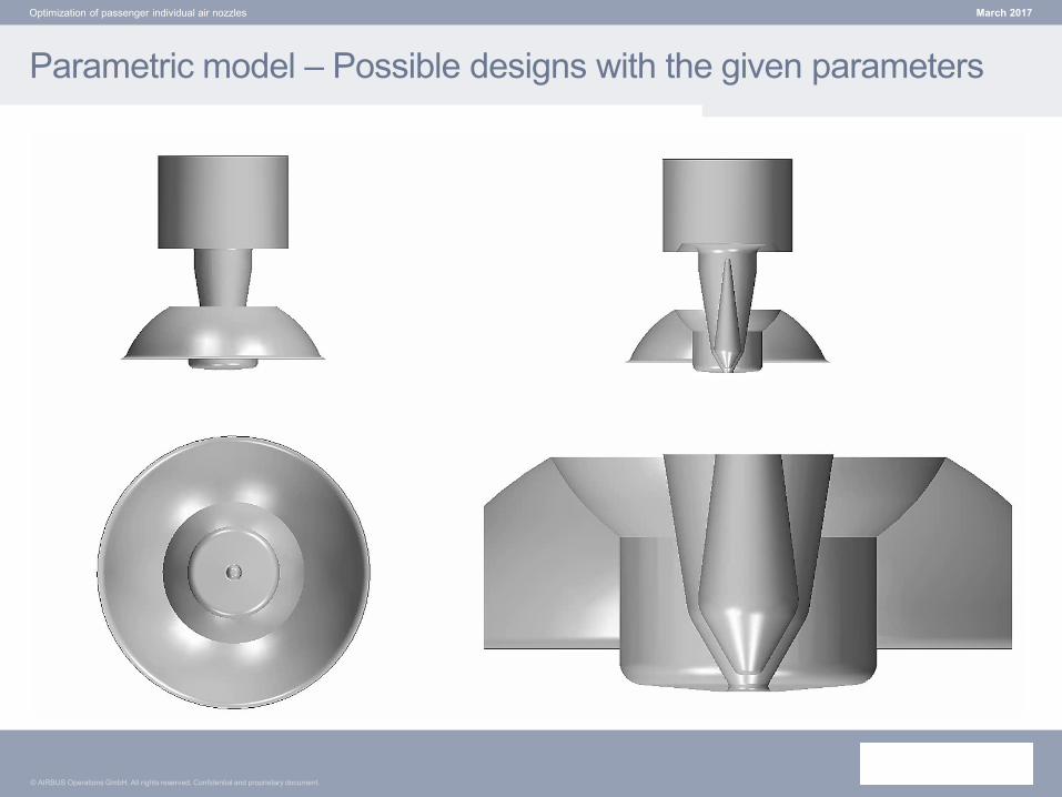
Parametric model – Possible designs with the given parameters
March 2017Optimization of passenger individual air nozzles

© AIRBUS Operations GmbH. All rights reserved. Confidential and proprietary document.
Setup of CFD model – Mesh and physics definition
Mesh:
• Trimmed mesh, cell count was
around 4 million for all models
• Three volume controls for
refinements in the jet region
• 5 prism layers
Continuum setup:
• 3D steady state
• Segregated flow solver
• Constant density air
• SST k-ω turbulence model
• All y+ wall treatment
March 2017Optimization of passenger individual air nozzles

© AIRBUS Operations GmbH. All rights reserved. Confidential and proprietary document.
Setup of CFD model – Monitors, stopping criteria
Monitors:
Moving average over last 500 iterations
(field mean monitor with sliding window)
for all target quantities (c_max, p_tot and
CoreArea)
Stopping criteria:
• Asymptotic limits (max-min) over last
500 iterations:
• 0.1 m/s for c_max
• 10.0 Pa for p_tot
• 5.0 cm^2 for CoreArea
• Maximum allowed iterations: 15000
(design considered invalid, if this limit is
reached)
March 2017Optimization of passenger individual air nozzles

© AIRBUS Operations GmbH. All rights reserved. Confidential and proprietary document.
Results – Baseline design
March 2017Optimization of passenger individual air nozzles

© AIRBUS Operations GmbH. All rights reserved. Confidential and proprietary document.
Results – Automated design optimization
• As both the minimization of the pressure loss and the air flow rate was an
objective, the air flow rate as added to the optimization as a non-geometric
parameter
• Simulations were run on 96 CPUs (4.75 day in total)
• Number of simulations:
• Total: 175
• Feasible designs: 35 = 20%
• Infeasible designs: 79 = 45 %
• Errors during creation of geometry: 61 = 35 % (quite high, target should be
around 10%)
March 2017Optimization of passenger individual air nozzles

© AIRBUS Operations GmbH. All rights reserved. Confidential and proprietary document.
Parametric model – Pressure drop
March 2017Optimization of passenger individual air nozzles

© AIRBUS Operations GmbH. All rights reserved. Confidential and proprietary document.
Parametric model – Velocity field of different designs
March 2017Optimization of passenger individual air nozzles

© AIRBUS Operations GmbH. All rights reserved. Confidential and proprietary document.
Results – Parallel plot of all designs
March 2017Optimization of passenger individual air nozzles
• For the best designs, following important parameters can be identified:
• beta (angle of inner cone): around 30 to 35 deg
• gap: always around 3.2 to 3.5 mm
• L3 & R1: both values together implicitely define the inner diameter of nozzle (outer part)
• air flow rate: all best designs have similar air flow rates to today’s design

© AIRBUS Operations GmbH. All rights reserved. Confidential and proprietary document.
Results – Top design
March 2017Optimization of passenger individual air nozzles

© AIRBUS Operations GmbH. All rights reserved. Confidential and proprietary document.
Results – Comparison between baseline and top design
Total pressure difference between inlet and end of upper cone is small and similar for
both designs (14.8 Pa for baseline, 5.2 Pa for top design).
→ Major part of pressure loss not created here, only little margin for improvement!
March 2017Optimization of passenger individual air nozzles
Baseline design Top design

© AIRBUS Operations GmbH. All rights reserved. Confidential and proprietary document.
Results – Comparison between baseline and top design
→ Dynamic pressure at nozzle outlet significantly lower and more equally distributed
at optimized design!
March 2017Optimization of passenger individual air nozzles
Baseline design Top design

© AIRBUS Operations GmbH. All rights reserved. Confidential and proprietary document.
Summary & conclusion
March 2017Optimization of passenger individual air nozzles
• A significant improvement of the pressure loss
charactaristic could be achieved while meeting all
performance requirements (air flow rate, air velocities,
core area of the jet)
• Turnaround time for actuall optimization process less
than a week!
• Biggest challenge remains creation of the CAD-input:
• Definition of meaningful parameters – otherwise the
intepretation is difficult
• Robustness of the geometry: failure rate should be low in
order to make sure that no good design is overlooked
• Further work to be done:
• Check of manufacturing and industrial design aspects
• Test of a prototype for validation of performance and
accoustical behavior

© AIRBUS Operations GmbH. All rights reserved. Confidential and proprietary document.
March 2017Optimization of passenger individual air nozzles
© Airbus Operations GmbH. All rights reserved. Confidential and proprietary document. This document and all information contained herein is the sole property of Airbus Operations GmbH. No intellectual property rights are granted by the delivery of this document
or the disclosure of its content. This document shall not be reproduced or disclosed to a third party without the express written consent of Airbus Operations GmbH. This document and its content shall not be used for any purpose other than that for which it is
supplied. The statements made herein do not constitute an offer. They are based on the mentioned assumptions and are expressed in good faith. Where the supporting grounds for these statements are not shown, Airbus Operations GmbH will be pleased to
explain the basis thereof. AIRBUS, its logo, A300, A310, A318, A319, A320, A321, A330, A340, A350, A380, A400M are registered trademarks.