optimization of ply angles in laminated composite structures by a hybrid, asynchronous, parallel...
TRANSCRIPT

Composite Structures 92 (2010) 2781–2790
Contents lists available at ScienceDirect
Composite Structures
journal homepage: www.elsevier .com/locate /compstruct
Optimization of ply angles in laminated composite structures by a hybrid,asynchronous, parallel evolutionary algorithm
David Keller *
Centre of Structure Technologies, ETH Zurich, 8092 Zurich, Switzerland
a r t i c l e i n f o
Article history:Available online 24 April 2010
Keywords:Ply angleOptimizationEvolutionary algorithmSensitivity analysis
0263-8223/$ - see front matter � 2010 Elsevier Ltd. Adoi:10.1016/j.compstruct.2010.04.003
* Tel.: +41 44 632 56 71; fax: +41 44 633 11 25.E-mail address: [email protected]: http://www.structures.ethz.ch.
a b s t r a c t
An evolutionary algorithm approach aimed at the global optimization of ply angles in laminated compos-ites is proposed. The algorithm is enriched by first-order local search and a niching strategy. Genetic var-iation operators are tailored to the special properties of ply angle optimization problems. Cyclic box-constraints are considered in the crossover, mutation, and niching operations. All experiments on threeacademic benchmark problems are able to identify a global optimal solution. Two case studies illustratethe applicability of the method on typical engineering problems.
� 2010 Elsevier Ltd. All rights reserved.
1. Introduction
The orientation of the plies in laminated composite structuresallows for a mass-neutral tuning of the mechanical properties ofthe final product. Even for existing designs the optimization ofply angles can be useful because there is typically only little influ-ence on manufacturing.
The assembly of homogenized laminate properties in a simula-tion model requires a rotation of the properties of each single lam-ina to a global laminate coordinate system. This rotation involvestrigonometric functions. Hence, objectives building on top ofmechanical properties of laminates are non-convex with respectto ply angles. Analytical approaches to the optimization of ply an-gles (like e.g. [1–6]) are only available for geometrically simplecases. The application of mathematical programming either risksto get stuck in a local optimal solution (which may be acceptedin some situations, like e.g. [7,8]) or requires extensive tuning ofthe optimizer itself in order to converge in the global optimal solu-tion (e.g. [9,10]). So far, a transformation of the original to a convexoptimization problem e.g. by lamination parameters is not avail-able for general shell structures but only for simple geometries[11–16]. Furthermore, the back-transformation from once foundoptimal lamination parameters to a real lay-up is a non-trivial taskand may require a second optimization step (cf. [17,18]).
Although numerically expensive, evolutionary approaches havebeen applied to ply angle optimization (e.g. [19–21]). In order toreduce the computational requirements of a global search by EAsan iterative procedure including a local gradient-based search isproposed by Huang and Haftka [22].
ll rights reserved.
Usually, the ply angle is considered to be constant within piecesof fabric. However, manufacturing processes like tow placementcan achieve locally varying fiber angles. An optimization methodexploiting this possibility is proposed by Blom et al. [23].
The here investigated method uses a manufacturing related,ply-wise parameterization, i.e. the ply angles are considered tobe constant within global plies or patches (see Section 3). Thisparameterization stays in contrast to often employed continuousfiber angle optimizations (CFAOs) where the reinforcement orien-tation is adapted at each point in the structure. The optimizationis carried out in a framework of an evolutionary algorithm (EA).In order to reduce the overall runtime, this algorithm is executedasynchronously and in parallel. Further on, to reduce the numberof function evaluations, a gradient-based, local search is incorpo-rated and used to construct a response model of the objective land-scape in already exploited regions.
2. Ply angle optimization: a non-linear optimization problemwith periodic search space
In the following we consider scalar-valued, box-constrained plyangle optimization problems of the form:
minimize FðxÞ ð1Þ
subject to : x 2 Rnj � p26 xi <
p2
ð2Þ
where x = [x1,x2, . . . ,xn]T is a vector of n ply angles. The objective F(x)is assembled from mechanical qualities of the structure like stiffnessand eigenfrequencies. These properties are evaluated by numericalsimulations, i.e. finite element analysis. Due to the geometricperiodicity in the ply angles F is periodic as well, i.e. F(x) = F(x + hp)for each h 2 Zn. If F has at least one minimum in the constrained box
Patch A
Patch B
Zone 1
Zone 2 Zone 3
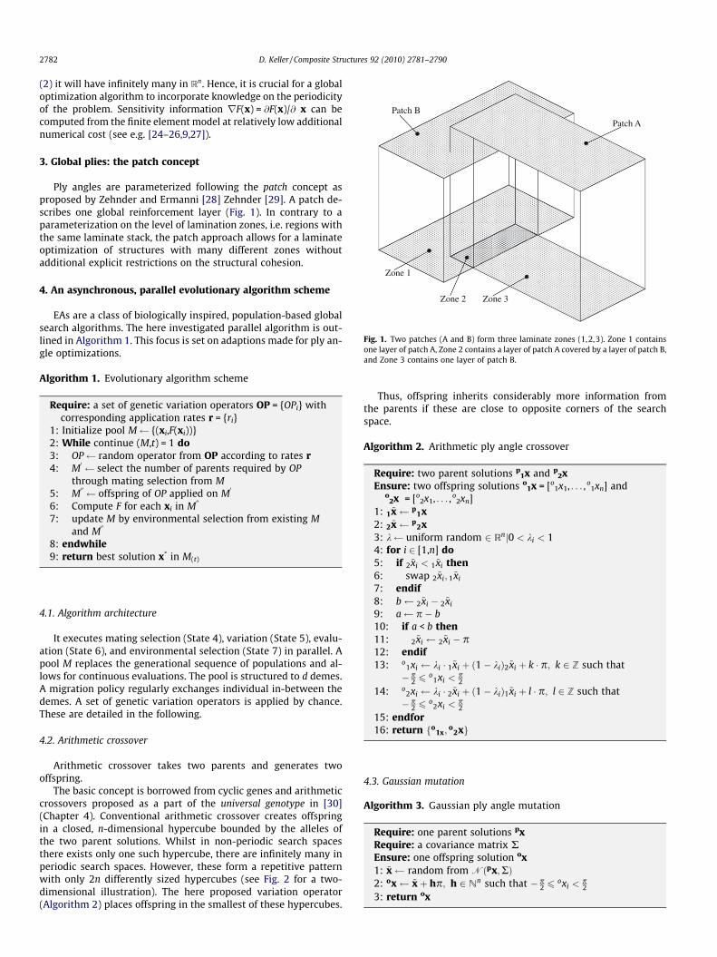
Fig. 1. Two patches (A and B) form three laminate zones (1,2,3). Zone 1 containsone layer of patch A, Zone 2 contains a layer of patch A covered by a layer of patch B,and Zone 3 contains one layer of patch B.
2782 D. Keller / Composite Structures 92 (2010) 2781–2790
(2) it will have infinitely many in Rn. Hence, it is crucial for a globaloptimization algorithm to incorporate knowledge on the periodicityof the problem. Sensitivity information rF(x) = @F(x)/@ x can becomputed from the finite element model at relatively low additionalnumerical cost (see e.g. [24–26,9,27]).
3. Global plies: the patch concept
Ply angles are parameterized following the patch concept asproposed by Zehnder and Ermanni [28] Zehnder [29]. A patch de-scribes one global reinforcement layer (Fig. 1). In contrary to aparameterization on the level of lamination zones, i.e. regions withthe same laminate stack, the patch approach allows for a laminateoptimization of structures with many different zones withoutadditional explicit restrictions on the structural cohesion.
4. An asynchronous, parallel evolutionary algorithm scheme
EAs are a class of biologically inspired, population-based globalsearch algorithms. The here investigated parallel algorithm is out-lined in Algorithm 1. This focus is set on adaptions made for ply an-gle optimizations.
Algorithm 1. Evolutionary algorithm scheme
Require: a set of genetic variation operators OP = {OPi} withcorresponding application rates r = {ri}
1: Initialize pool M {(xi,F(xi))}2: While continue (M,t) = 1 do3: OP random operator from OP according to rates r4: M
0 select the number of parents required by OPthrough mating selection from M
5: M00 offspring of OP applied on M
0
6: Compute F for each xi in M00
7: update M by environmental selection from existing Mand M
00
8: endwhile9: return best solution x* in M(t)
4.1. Algorithm architecture
It executes mating selection (State 4), variation (State 5), evalu-ation (State 6), and environmental selection (State 7) in parallel. Apool M replaces the generational sequence of populations and al-lows for continuous evaluations. The pool is structured to d demes.A migration policy regularly exchanges individual in-between thedemes. A set of genetic variation operators is applied by chance.These are detailed in the following.
4.2. Arithmetic crossover
Arithmetic crossover takes two parents and generates twooffspring.
The basic concept is borrowed from cyclic genes and arithmeticcrossovers proposed as a part of the universal genotype in [30](Chapter 4). Conventional arithmetic crossover creates offspringin a closed, n-dimensional hypercube bounded by the alleles ofthe two parent solutions. Whilst in non-periodic search spacesthere exists only one such hypercube, there are infinitely many inperiodic search spaces. However, these form a repetitive patternwith only 2n differently sized hypercubes (see Fig. 2 for a two-dimensional illustration). The here proposed variation operator(Algorithm 2) places offspring in the smallest of these hypercubes.
Thus, offspring inherits considerably more information fromthe parents if these are close to opposite corners of the searchspace.
Algorithm 2. Arithmetic ply angle crossover
Require: two parent solutions p1x and p
2xEnsure: two offspring solutions o
1x = [o1x1, . . . , o
1xn] ando
2x = [o2x1, . . . , o
2xn]1: 1~x p
1x2: 2~x p
2x3: k uniform random 2 Rnj0 < ki < 14: for i 2 [1,n] do5: if 2~xi < 1~xi then6: swap 2~xi; 1~xi
7: endif8: b 2~xi � 2~xi
9: a p � b10: if a < b then11: 2~xi 2~xi � p12: endif13: o
1xi ki � 1~xi þ ð1� kiÞ2~xi þ k � p; k 2 Z such that� p
2 6o
1xi <p2
14: o2xi ki � 2~xi þ ð1� kiÞ1~xi þ l � p; l 2 Z such that� p
2 6o
2xi <p2
15: endfor16: return o
1x;o
2xf g
4.3. Gaussian mutation
Algorithm 3. Gaussian ply angle mutation
Require: one parent solutions pxRequire: a covariance matrix REnsure: one offspring solution ox1: ~x random from Nðpx;RÞ2: ox ~xþ hp; h 2 Nn such that � p
2 6oxi <
p2
3: return ox
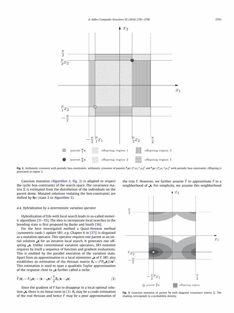
Fig. 2. Arithmetic crossover with periodic box-constraints: arithmetic crossover of parents p1x = [p
1x1, p1x2]T and p
2x = [p2x1, p
2x1]T with periodic box-constraints. Offspring isgenerated in region 2.
D. Keller / Composite Structures 92 (2010) 2781–2790 2783
Gaussian mutation (Algorithm 3, Fig. 3) is adapted to respectthe cyclic box-constraints of the search space. The covariance ma-trix R is estimated from the distribution of the individuals on the
parent deme. Mutated solutions violating the box-constraints areshifted by hp (state 2 in Algorithm 3).Fig. 3. Gaussian mutation of parent px with diagonal covariance matrix R. Theshading corresponds to a probability density.
4.4. Hybridization by a deterministic variation operator
Hybridization of EAs with local search leads to so-called memet-ic algorithms [31–35]. The idea to incorporate local searches in thebreeding state is first proposed by Burke and Smith [36].
For the here investigated method a Quasi-Newton method(symmetric-rank-1 update SR1, e.g. Chapter 6 in [37]) is disguisedas a mutation operator. This operator requires one parent as an ini-tial solution px for an iterative local search. It generates one off-spring ox. Unlike conventional variation operators, SR1-mutationrequires by itself a sequence of function and gradient evaluations.This is enabled by the parallel execution of the variation state.Apart from an approximation to a local minimizer ox of F, SR1 alsoestablishes an estimation of the Hessian matrix Bk � @2F(ox)/@x2.This estimation is used to span a quadratic Taylor approximationof the response close to ox further called a niche:
eF ðxÞ ¼ FðoxÞ þ ðx� oxÞT 12
Bkðx� oxÞ ð3Þ
Since the gradient of F has to disappear in a local optimal solu-tion ox, there is no linear term in (3). Bk may be a crude estimationof the real Hessian and hence eF may be a poor approximation of
the true F. However, we further assume eF to approximate F in aneighborhood of ox. For simplicity, we assume this neighborhood

2784 D. Keller / Composite Structures 92 (2010) 2781–2790
to be bound by a contour surface of eF . Contour surfaces of eF areellipsoidals and can be parameterized by the quadratic term in (3):
dðx; oxÞ ¼ffiffiffiffiffiffiffiffiffiffiffiffiffiffiffiffiffiffiffiffiffiffiffiffiffiffiffiffiffiffiffiffiffiffiffiffiffiffiffiffiffiffiffiffiffiffiðx� oxÞT 1
2Bkðx� oxÞ
rð4Þ
This so-called Mahalanobis distance describes a distance of anarbitrary point x on a contour line of eF to the niche center ox. Itis used as a scalar value to describe and later adapt the size ofthe niche (corresponding to the niche radius in other nichingmethods). An initial estimate for this niche radius is given fromthe distance between the niche center and the start point of theiterative path of SR1, i.e. d0 = d(px, ox). The niche radius is itera-tively adapted based on the correlation of the predicted and actualresponse of further evaluations within the niche. In order to focusthe evolutionary search to unexploited regions, solutions within aniche have a lower selection probability for mating selection. Thisis achieved by fitness sharing (see [38,39]), i.e. a fitness penalty foreach individual inside a niche. Hence, the fitness used in matingselections is set to F
0with
F 0ðxÞ ¼ FðxÞ � ð1þmcðxÞÞsgnFðxÞ ð5Þ
mc(x) is called niche count and computed from the sharing functionsh over all niches i with niche centers ix.
mcðxÞ ¼X
i
shðx; ixÞ ð6Þ
The sharing function describes a normalized proximity of x to aniche with center ix and radius d0:
shðx; ixÞ ¼1� dðx;ixÞ
d0dðx; ixÞ 6 d0
0 otherwiseð7Þ
Iterates of SR1-mutation leaving the periodic box are moved by aperiod p in the appropriate direction. Distance measures in theniching model are evaluated over the shortest distance consideringthe periodicity of the problem.
5. Implementation
The method is implemented in an object-oriented code in thePython programming language1 (version 2.5). Grid Engine 6 N12 isemployed as a queueing system on a heterogeneous cluster consist-ing of 28 blade computers and two workstations with two CPUseach. MySQL 5.03 serves as a database server, InnoDB4 is used asunderlaying storage engine. The database service as well as thescheduler run on the same additional server computer. The commer-cial finite element code ABAQUS (version 6.8) is employed for thestructural simulations. Sensitivities are computed by a direct differ-entiation scheme (see Section 2.18 in [40]).
6. Numerical experiments
This section presents investigations of the algorithms behaviorin geometrically simple laminate optimization problems. In orderto illustrate objectives and results the problems are restricted totwo dimensions. The material data for all experiments and theexamples in Section 7 are given in Appendix A.
All experiments in this section use the same algorithm configu-ration: The pool size is set to 60 individuals. The population is
1 http://www.python.org.2 http://gridengine.sunsource.net.3 http://www.mysql.com.4 http://www.innodb.com.
divided into three demes. The algorithm is stopped after 4000 eval-uations. The rates for the variation operators are 0.05 for Gaussianmutation, 0.05 for SR1-mutation, and 0.90 for arithmetic crossover.Migration between the demes is carried out after 600 evaluationseach. Since the differentiation method applies a combined ana-lytic/numeric procedure, the resulting gradient information is af-fected by considerable numerical noise. Hence, the tolerance � inSR1-mutation (i.e. the algorithm stops if krF(x)k 6 �) is set to5 � 10�3.
6.1. Minimal compliance design of a tensile specimen
A rectangular tensile specimen (Fig. 4a, length 250 mm, width100 mm, clamped at one side and uniformly loaded with 0.01 N/mm at the other side) consisting of a symmetric laminate of mate-rial 1 is investigated.
The laminate is parameterized as [±30,±x1,±x2]s. The ±30� plieshave a thickness of 1.25 mm. The remaining inner layers (±x1,±x2)are 0.125 mm thick. The ply angles x1 and x2 shall be optimized inorder to minimize the elastic strain energy of the loadedstructure.
A contour plot illustrating the objective as a function of theoptimization variables is given in Fig. 4b. From there, an obviousoptimal design is given at x = 0, because then the fibers are ori-ented along the load direction. Ply angles of 90�, i.e. inx = [0,±90], x = [±90,±90] or x = [±90,0], obstruct the transversecontraction and hence transfer load to the outer 30� plies whatleads to additional local optima.
The runs are compared by the minimal fitness found after a cer-tain number of evaluations (Fig. 5a) Due to the stochastic compo-nents in the algorithm, the 10 runs do not show the same curve.However, after 500 evaluations all runs converge to a solution ofequal quality. Table 1 summarizes the fitness values, correspond-ing ply angles and detected niches for the different runs. Onlyone run is capable to detect all niches (run 5). However, all runsconverge in the same solution, i.e. the global optimal one. Notably,run 3 and 4 do not identify a niche there.
6.2. Minimal compliance design of a rectangular plate
A rectangular plate (length 500 mm, width 250 mm) is loadedby an concentrated, central, out-of-plane load F = 1 N (Fig. 6a). Asymmetric laminate [x1,x2]s from two plies of material 1 is applied(ply thickness 0.125 mm). The objective is again to minimize thetotal strain energy. A contour plot of the objective is depicted inFig. 6b.
The best fitness averaged over all 10 runs is illustrated in Fig. 5band listed in Table 2. After 300 evaluations all runs converge to asolution of equal quality. All runs identify both global optimal solu-tions. Due to the relative large tolerance in the SR1-mutation sixout of 10 runs identify an additional local optimum in the plateauregion at x1 = 75, x2 = 39.
6.3. Eigenfrequency optimization of a circular disk
The first natural frequency of a circular disk (radius 250 mm,supported at the boundary) shall be optimized. The laminate con-sists of a non-symmetric laminate of two plies of material 1 (plythickness 1 mm), i.e. [x1,x2]. Since the disk geometry has no prefer-ence direction, the contour lines in Fig. 7 approximate straightlines (slight preference directions induced by the finite elementdiscretization exist).
The results are illustrated in Fig. 5c and summarized in Table 3.Run 2 identified a niche at [�8.74,�8.81], run 4 one at [8.79,8.76].All runs identify a solution with x1 � x2.

(a)
(b)
Fig. 4. Geometry and objective of the tensile specimen experiment. (a) Support and loading of the tensile specimen experiment. The structure is clamped at the left side and auniform line-load of 0.01 N/mm is applied to right side. Positive ply angles are measured from n to g. (b) Contour plot of the objective for the tensile specimen experiment as afunction of the ply angles x1 and x2 (in degree). The contour lines are interpolated in a regular grid of 1296 evaluations (5� raster).
(a) Tensile specimen (b) Rectangular plate
(c) Disk
Fig. 5. Convergence plot for numerical experiments: convergence plot for the numerical experiments: best fitness found as a function of the number of evaluations (on alogarithmic scale) averaged over 10 runs.
D. Keller / Composite Structures 92 (2010) 2781–2790 2785

Table 1Best solutions and detected niches for the tensile specimen experiment: Fw in N mm and ply angles x1 and x2 in degree. The niches are centered at the location given in the tablehead.
Best solution Detected niches
Run Fw xH
1 xH
2 �90�90
� ��90
0
� �0
�90
� �00
� �
1 0.156032 0.023570 �0.140808 U U U
2 0.156031 0.008006 �0.003092 U U
3 0.156031 �0.007092 �0.011557 U U U
4 0.156032 0.069002 0.080666 U U
5 0.156031 �0.000620 �0.024971 U U U U
6 0.156031 0.156031 �0.036184 U
7 0.156031 0.006691 �0.021751 U U
8 0.156031 0.026069 �0.020761 U U
9 0.156031 0.004075 0.004032 U
10 0.156031 �0.003067 �0.002079 U U
Avg.(Fw) 0.156031Std.(Fw) 4.21e�07
a
a
b
b
F
0.46
0.46
0.48
0.48
0.49
0.49
0.49
0.51
0.51
0.51
0.51
0.52
0.52
0.52
0.52
0.54
0.54
0.54
0.54
0.550.55
0.55
0.55
0.560.56
0.560.58
0.58
0.6
0.6
0.61
0.61
0.63
0.63
90 75 60 45 30 15 0 15 30 45 60 7590
75
60
45
30
15
0
15
30
45
60
75
90 75 60 45 30 15 0 15 30 45 60 75
90
75
60
45
30
15
0
15
30
45
60
75
(a) (b)
Fig. 6. Geometry and objective of the rectangular plate experiment. (a) Support and loading of the rectangular plate experiment. A central out-of-plane load perpendicular tothe plate surface is introduced. The plate is clamped (a) at one part of the boundary and simply supported at another (b). Positive ply angles are measured from n to g. (b)Contour plot of the objective for the rectangular plate experiment. The objective corresponds to the elastic strain energy of the structure (in N mm) as a function of the plyangles x1 and x2 (in degree). The contour lines are interpolated in a regular grid of 1296 evaluations (5� raster).
Table 2Best solutions for the rectangular plate experiment: best solutions for the rectangularplate experiment: Fw in N mm and ply angles x1 and x2 in degree.
Best solution Detected niches
Run Fw xH
1 xH
2 �2853
� �28�53
� �7539
� �
1 0.456322 �27.884157 53. 289815 U U U
2 0.456322 �27.893398 53.270000 U U U
3 0.456322 27.917151 �53.285163 U U U
4 0.456322 �27.905972 53.276329 U U
5 0.456322 �27.981053 53.285953 U U U
6 0.456322 27.987766 �53.201019 U U
7 0.456322 27.906112 �53.268347 U U
8 0.456322 �27.897110 53.265182 U U U
9 0.456322 �27.897664 53.269157 U U
10 0.456322 27.820767 �53.237995 U U U
Avg.(Fw) 0.456322Std.(Fw) <1e�08
2786 D. Keller / Composite Structures 92 (2010) 2781–2790
7. Applications
The following two examples shall illustrate the usability of themethod in typical engineering applications. In contrary to the
numerical examples in the section above, there is no detailed im-age of the objective as a function of the ply angles. Especially, thereis no knowledge on the location of local or global optima. Hence,the results obtained can no longer substantiate a claim for globaloptimality.
7.1. Minimum compliance design of an aircraft side rudder
An aircraft side rudder is a control surface used to induce a yawmoment. It is attached to the aircraft’s vertical tail and allows forrotations around the aircraft’s yaw axis (Fig. 8). The steering mo-ments are induced into the bottom rib, a second attachment pointis formed by two short supports on the eighth rib. The rudder issubject to aerodynamic forces acting on its skin. An additional,non-structural mass is positioned in the front top section of thestructure to balance steering reactions. Depending on the flightstate, this mass induces considerable forces of inertia. The struc-ture is built from a single spar and several ribs supporting the aero-dynamic active skin. The rounded nose allows for a gap-freeconnection to the vertical tail. The trailing edge gives support toa trim-rudder. The component is nearly symmetric to the x–z-plane. The slight asymmetry is induced by the trailing edge whichis inclined to the port side to give place for the trim-rudder attach-ment and actuation devices.

Table 3Best solutions for the disk experiment: best solutions for the disk experiment: Fw
corresponds to the first natural frequency �f0 in Hz, ply angles x1 and x2 in degree.
Run Fw xH
1 xH
2
1 �42.89790 �83.959927 �83.9651292 �42.89800 �72.316472 �72.3164723 �42.89800 �37.565863 �37.6047454 �42.89780 �8.304790 �8.4761445 �42.89800 �14.739024 �14.7571516 �42.89800 �19.100151 �19.1001517 �42.89800 �69.513538 �69.4118338 �42.89800 �58.314708 �58.3826309 �42.89800 �70.910319 �70.85847110 �42.89800 �58.910033 �59.033110
Avg.(Fw) �42.897970Std.(Fw) 6.75e�05
(a) Isometric view (b)Web
Fig. 8. Aircraft side rudder structure: aircraft side rudder structure. The rudder isattached to the vertical tail whereas the upper attachment point enables forrotations around the vertical axis. The lower support is used to introduce thesteering moment and is hence fixed in the analysis.
39
39
39
39
39
39
3939
40
40
4040
40
40
40
40
41
41
41
4141
41
4141
42 42
4242
90 75 60 45 30 15 0 15 30 45 60 75
90
75
60
45
30
15
0
15
30
45
60
75
90 75 60 45 30 15 0 15 30 45 60 75
90
75
60
45
30
15
0
15
30
45
60
75
Fig. 7. Contour plot of the objective for the rectangular plate experiment: contourplot of the objective landscape for the disk experiment. The objective correspondsto the lowest eigenfrequency as a function of the ply angles x1 and x2 (in degree).The contour lines are interpolated in a regular grid of 1296 evaluations (5� raster).
D. Keller / Composite Structures 92 (2010) 2781–2790 2787
The loads of a dimensioning load case are introduced by theshear-moment-and-torque method (cf. e.g. Appendix A in [41]).The resulting displacement field is a superposition of a torsionaldeformation around the z axis and two-point bending betweenthe support points.
The structure consists of a ground laminate and shall be sym-metrically reinforced by five non-overlapping patches on the skin(Fig. 9). The internal structure (ribs, spar, and trailing edge) consistof a quasi-isotropic laminate (Material 1, thickness 1.5 mm). Theremaining laminates are all built from plies of material 1 of0.125 mm thickness: the nose (Section 5 in Fig. 9b) is covered bya laminate [±x1,x2]s. The skin is covered by a laminate [±x3]s. Thislaminate is reinforced by additional plies, i.e. [±x3,±x4]s in Section 1,[±x3,±x5]s in Section 2, [±x3,±x6]s in Section 3, and [±x3,±x7]s in Sec-tion 4 respectively.
The optimization is carried out to maximize the stiffness, i.e. tominimize the elastic strain energy. The decision variables are theseven ply angles [x1,x2, . . . ,x7]T.
7.1.1. Results and discussionThe optimization is carried out for 10,000 function evaluations.
All evaluations are plotted in Fig. 10. SR1-mutation identifies 29niches. The best individual found has an objective value F(xw) =436.558 N mm with xw = [�25.859, 25.679, �57.405, 0.303,�57.461 , 59.837, 49.077]T. It is created after 5131 evaluations asoffspring of SR1-mutation. Its gradient rF(xw) evaluates to[�3.450, 3.803, 14.0219, 6.386, �1.798, �4.666, 1.301]T � 10�4.
The ply angles x1 and x2 reinforce the wing nose box against tor-sion deflections. The same holds for the skin x3 and patches 3 (x6)and 4 (x7). Patch 1 (x4) is affected by the fixed support in the lowestrib. Ply angle optimization is able to increase the stiffness of thestructure by roughly 5% when compared to the best solution inthe initial population.
7.2. Eigenfrequency optimization of a racing car rear wing
A racing car rear wing (Fig. 11) is a load carrying structure de-signed to exert an aerodynamic down force on the rear wheels ofthe car to maximize traction. At the same time, a car’s weight shallbe minimized. Harmonic vibrations of the rear wing reduce theaerodynamic performance and may, if in transverse direction, evencause collisions with carriage components. Hence, the most criticallowest natural frequency shall be maximized. The transverseeigenmodes are mainly dominated by the stiffness of the sideplates and their connection to the car body, i.e. the lower wing.Hence, ply angles of reinforcement plies in the side plates andthe lower wing shall be optimized. The side plates consist of four
(a) Skin (b) Laminate sec-tions
Fig. 9. Laminate on the aircraft side rudder: laminate on the aircraft side rudder: anexisting ground laminate on the skin is reinforced with five non-overlappingpatches. The ply angles are measured from n to g.
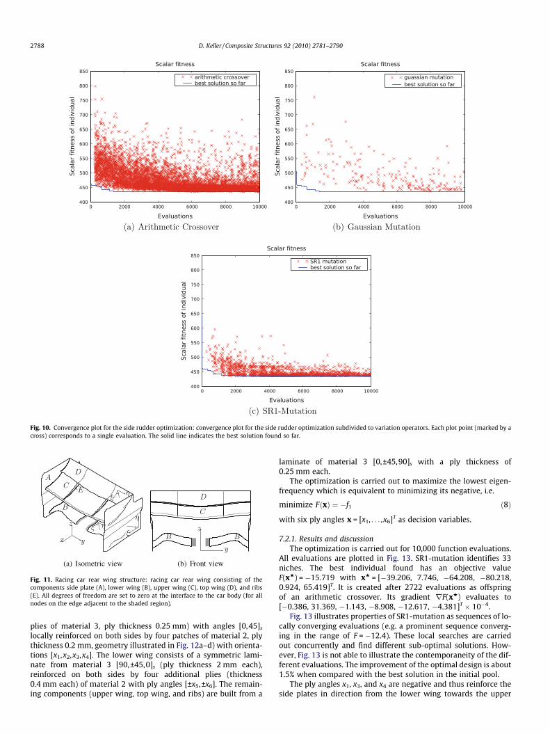
Fig. 10. Convergence plot for the side rudder optimization: convergence plot for the side rudder optimization subdivided to variation operators. Each plot point (marked by across) corresponds to a single evaluation. The solid line indicates the best solution found so far.
(a) Isometric view (b) Front view
Fig. 11. Racing car rear wing structure: racing car rear wing consisting of thecomponents side plate (A), lower wing (B), upper wing (C), top wing (D), and ribs(E). All degrees of freedom are set to zero at the interface to the car body (for allnodes on the edge adjacent to the shaded region).
2788 D. Keller / Composite Structures 92 (2010) 2781–2790
plies of material 3, ply thickness 0.25 mm) with angles [0,45]s
locally reinforced on both sides by four patches of material 2, plythickness 0.2 mm, geometry illustrated in Fig. 12a–d) with orienta-tions [x1,x2,x3,x4]. The lower wing consists of a symmetric lami-nate from material 3 [90,±45,0]s (ply thickness 2 mm each),reinforced on both sides by four additional plies (thickness0.4 mm each) of material 2 with ply angles [±x5,±x6]. The remain-ing components (upper wing, top wing, and ribs) are built from a
laminate of material 3 [0,±45,90]s with a ply thickness of0.25 mm each.
The optimization is carried out to maximize the lowest eigen-frequency which is equivalent to minimizing its negative, i.e.
minimize FðxÞ ¼ �f1 ð8Þ
with six ply angles x = [x1, . . . ,x6]T as decision variables.
7.2.1. Results and discussionThe optimization is carried out for 10,000 function evaluations.
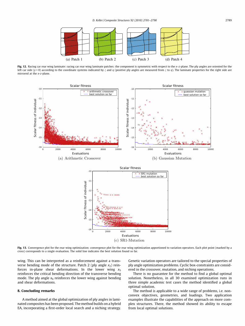
All evaluations are plotted in Fig. 13. SR1-mutation identifies 33niches. The best individual found has an objective valueF(xw) = �15.719 with xw = [�39.206, 7.746, �64.208, �80.218,0.924, 65.419]T. It is created after 2722 evaluations as offspringof an arithmetic crossover. Its gradient rF(xw) evaluates to[�0.386, 31.369, �1.143, �8.908, �12.617, �4.381]T � 10�4.
Fig. 13 illustrates properties of SR1-mutation as sequences of lo-cally converging evaluations (e.g. a prominent sequence converg-ing in the range of F = �12.4). These local searches are carriedout concurrently and find different sub-optimal solutions. How-ever, Fig. 13 is not able to illustrate the contemporaneity of the dif-ferent evaluations. The improvement of the optimal design is about1.5% when compared with the best solution in the initial pool.
The ply angles x1, x3, and x4 are negative and thus reinforce theside plates in direction from the lower wing towards the upper
(a) Patch 1 (b) Patch 2 (c) Patch 3 (d) Patch 4
Fig. 12. Racing car rear wing laminate: racing car rear wing laminate patches: the component is symmetric with respect to the x–z-plane. The ply angles are oriented for theleft car side (y > 0) according to the coordinate systems indicated by n and g (positive ply angles are measured from n to g). The laminate properties for the right side aremirrored at the x-z-plane.
Fig. 13. Convergence plot for the rear wing optimization: convergence plot for the rear wing optimization apportioned to variation operators. Each plot point (marked by across) corresponds to a single evaluation. The solid line indicates the best solution found so far.
D. Keller / Composite Structures 92 (2010) 2781–2790 2789
wing. This can be interpreted as a reinforcement against a trans-verse bending mode of the structure. Patch 2 (ply angle x2) rein-forces in-plane shear deformations. In the lower wing x5
reinforces the critical bending direction of the transverse bendingmode. The ply angle x6 reinforces the lower wing against bendingand shear deformations.
8. Concluding remarks
A method aimed at the global optimization of ply angles in lami-nated composites has been proposed. The method builds on a hybridEA, incorporating a first-order local search and a niching strategy.
Genetic variation operators are tailored to the special properties ofply angle optimization problems. Cyclic box-constraints are consid-ered in the crossover, mutation, and niching operations.
There is no guarantee for the method to find a global optimalsolution. Nonetheless, in all 30 examined optimization runs inthree simple academic test cases the method identified a globaloptimal solution.
The method is applicable to a wide range of problems, i.e. non-convex objectives, geometries, and loadings. Two applicationexamples illustrate the capabilities of the approach on more com-plex structures. There, the method showed its ability to escapefrom local optimal solutions.
2790 D. Keller / Composite Structures 92 (2010) 2781–2790
Acknowledgements
This work contributes to the project Unified Topology and ShapeDesign Optimization of Composite Structures gratefully supported bythe Swiss National Science Foundation (SNF 200021-II 9689I1).Thanks go to Prof. Paolo Ermanni, head of the Centre of StructureTechnologies, for enabling this research, to Florian Hürlimann forhis help in the modeling of the airplane side rudder, and to Dr. Ger-ald Kress, Benjamin Schläpfer, and Ursula Keller for their com-ments and corrections to the manuscript.
Appendix A. Material data
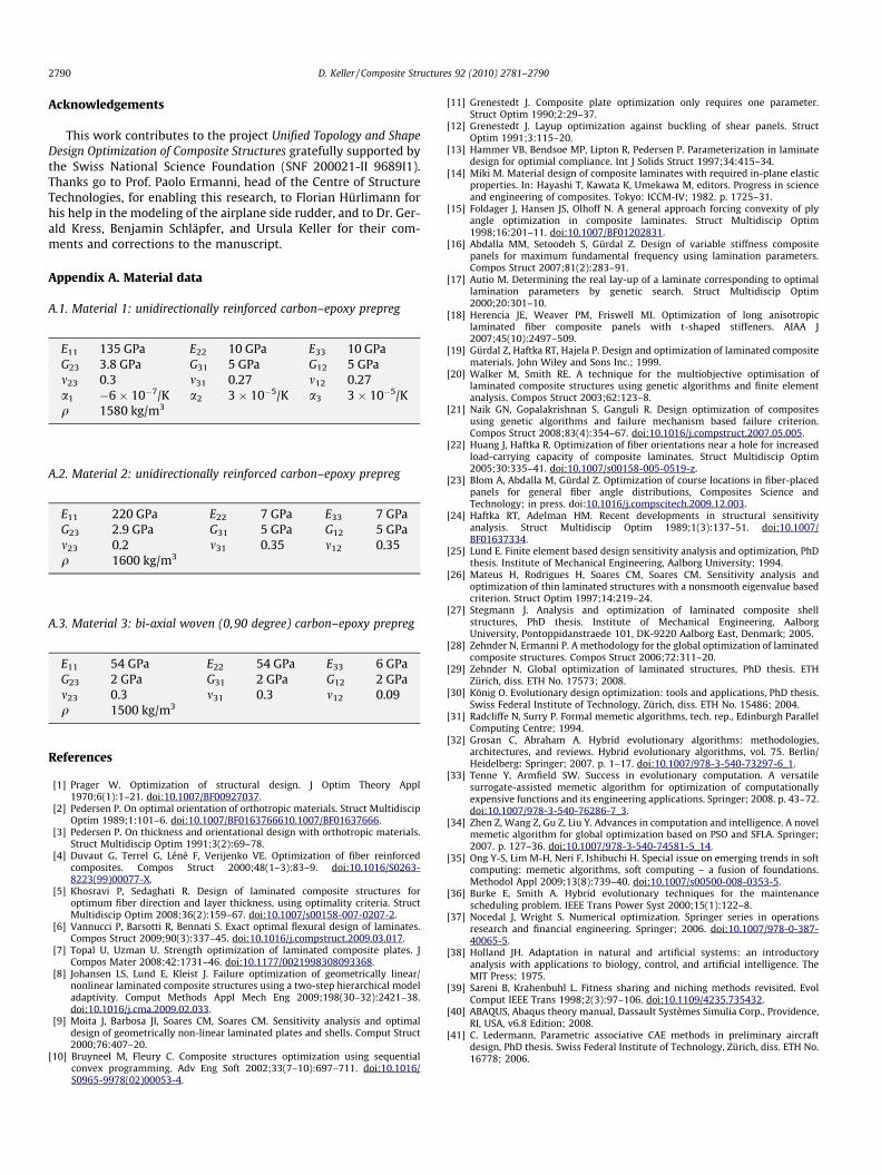
A.1. Material 1: unidirectionally reinforced carbon–epoxy prepreg
E11
135 GPa E22 10 GPa E33 10 GPa G23 3.8 GPa G31 5 GPa G12 5 GPa m23 0.3 m31 0.27 m12 0.27 a1 �6 � 10�7/K a2 3 � 10�5/K a3 3 � 10�5/K q 1580 kg/m3A.2. Material 2: unidirectionally reinforced carbon–epoxy prepreg
E11
220 GPa E22 7 GPa E33 7 GPa G23 2.9 GPa G31 5 GPa G12 5 GPa m23 0.2 m31 0.35 m12 0.35 q 1600 kg/m3A.3. Material 3: bi-axial woven (0,90 degree) carbon–epoxy prepreg
E11
54 GPa E22 54 GPa E33 6 GPa G23 2 GPa G31 2 GPa G12 2 GPa m23 0.3 m31 0.3 m12 0.09 q 1500 kg/m3References
[1] Prager W. Optimization of structural design. J Optim Theory Appl1970;6(1):1–21. doi:10.1007/BF00927037.
[2] Pedersen P. On optimal orientation of orthotropic materials. Struct MultidiscipOptim 1989;1:101–6. doi:10.1007/BF0163766610.1007/BF01637666.
[3] Pedersen P. On thickness and orientational design with orthotropic materials.Struct Multidiscip Optim 1991;3(2):69–78.
[4] Duvaut G, Terrel G, Léné F, Verijenko VE. Optimization of fiber reinforcedcomposites. Compos Struct 2000;48(1–3):83–9. doi:10.1016/S0263-8223(99)00077-X.
[5] Khosravi P, Sedaghati R. Design of laminated composite structures foroptimum fiber direction and layer thickness, using optimality criteria. StructMultidiscip Optim 2008;36(2):159–67. doi:10.1007/s00158-007-0207-2.
[6] Vannucci P, Barsotti R, Bennati S. Exact optimal flexural design of laminates.Compos Struct 2009;90(3):337–45. doi:10.1016/j.compstruct.2009.03.017.
[7] Topal U, Uzman U. Strength optimization of laminated composite plates. JCompos Mater 2008;42:1731–46. doi:10.1177/0021998308093368.
[8] Johansen LS, Lund E, Kleist J. Failure optimization of geometrically linear/nonlinear laminated composite structures using a two-step hierarchical modeladaptivity. Comput Methods Appl Mech Eng 2009;198(30–32):2421–38.doi:10.1016/j.cma.2009.02.033.
[9] Moita J, Barbosa JI, Soares CM, Soares CM. Sensitivity analysis and optimaldesign of geometrically non-linear laminated plates and shells. Comput Struct2000;76:407–20.
[10] Bruyneel M, Fleury C. Composite structures optimization using sequentialconvex programming. Adv Eng Soft 2002;33(7–10):697–711. doi:10.1016/S0965-9978(02)00053-4.
[11] Grenestedt J. Composite plate optimization only requires one parameter.Struct Optim 1990;2:29–37.
[12] Grenestedt J. Layup optimization against buckling of shear panels. StructOptim 1991;3:115–20.
[13] Hammer VB, Bendsoe MP, Lipton R, Pedersen P. Parameterization in laminatedesign for optimial compliance. Int J Solids Struct 1997;34:415–34.
[14] Miki M. Material design of composite laminates with required in-plane elasticproperties. In: Hayashi T, Kawata K, Umekawa M, editors. Progress in scienceand engineering of composites. Tokyo: ICCM-IV; 1982. p. 1725–31.
[15] Foldager J, Hansen JS, Olhoff N. A general approach forcing convexity of plyangle optimization in composite laminates. Struct Multidiscip Optim1998;16:201–11. doi:10.1007/BF01202831.
[16] Abdalla MM, Setoodeh S, Gürdal Z. Design of variable stiffness compositepanels for maximum fundamental frequency using lamination parameters.Compos Struct 2007;81(2):283–91.
[17] Autio M. Determining the real lay-up of a laminate corresponding to optimallamination parameters by genetic search. Struct Multidiscip Optim2000;20:301–10.
[18] Herencia JE, Weaver PM, Friswell MI. Optimization of long anisotropiclaminated fiber composite panels with t-shaped stiffeners. AIAA J2007;45(10):2497–509.
[19] Gürdal Z, Haftka RT, Hajela P. Design and optimization of laminated compositematerials. John Wiley and Sons Inc.; 1999.
[20] Walker M, Smith RE. A technique for the multiobjective optimisation oflaminated composite structures using genetic algorithms and finite elementanalysis. Compos Struct 2003;62:123–8.
[21] Naik GN, Gopalakrishnan S, Ganguli R. Design optimization of compositesusing genetic algorithms and failure mechanism based failure criterion.Compos Struct 2008;83(4):354–67. doi:10.1016/j.compstruct.2007.05.005.
[22] Huang J, Haftka R. Optimization of fiber orientations near a hole for increasedload-carrying capacity of composite laminates. Struct Multidiscip Optim2005;30:335–41. doi:10.1007/s00158-005-0519-z.
[23] Blom A, Abdalla M, Gürdal Z. Optimization of course locations in fiber-placedpanels for general fiber angle distributions, Composites Science andTechnology; in press. doi:10.1016/j.compscitech.2009.12.003.
[24] Haftka RT, Adelman HM. Recent developments in structural sensitivityanalysis. Struct Multidiscip Optim 1989;1(3):137–51. doi:10.1007/BF01637334.
[25] Lund E. Finite element based design sensitivity analysis and optimization, PhDthesis. Institute of Mechanical Engineering, Aalborg University; 1994.
[26] Mateus H, Rodrigues H, Soares CM, Soares CM. Sensitivity analysis andoptimization of thin laminated structures with a nonsmooth eigenvalue basedcriterion. Struct Optim 1997;14:219–24.
[27] Stegmann J. Analysis and optimization of laminated composite shellstructures, PhD thesis. Institute of Mechanical Engineering, AalborgUniversity, Pontoppidanstraede 101, DK-9220 Aalborg East, Denmark; 2005.
[28] Zehnder N, Ermanni P. A methodology for the global optimization of laminatedcomposite structures. Compos Struct 2006;72:311–20.
[29] Zehnder N. Global optimization of laminated structures, PhD thesis. ETHZürich, diss. ETH No. 17573; 2008.
[30] König O. Evolutionary design optimization: tools and applications, PhD thesis.Swiss Federal Institute of Technology, Zürich, diss. ETH No. 15486; 2004.
[31] Radcliffe N, Surry P. Formal memetic algorithms, tech. rep., Edinburgh ParallelComputing Centre; 1994.
[32] Grosan C, Abraham A. Hybrid evolutionary algorithms: methodologies,architectures, and reviews. Hybrid evolutionary algorithms, vol. 75. Berlin/Heidelberg: Springer; 2007. p. 1–17. doi:10.1007/978-3-540-73297-6_1.
[33] Tenne Y, Armfield SW. Success in evolutionary computation. A versatilesurrogate-assisted memetic algorithm for optimization of computationallyexpensive functions and its engineering applications. Springer; 2008. p. 43–72.doi:10.1007/978-3-540-76286-7_3.
[34] Zhen Z, Wang Z, Gu Z, Liu Y. Advances in computation and intelligence. A novelmemetic algorithm for global optimization based on PSO and SFLA. Springer;2007. p. 127–36. doi:10.1007/978-3-540-74581-5_14.
[35] Ong Y-S, Lim M-H, Neri F, Ishibuchi H. Special issue on emerging trends in softcomputing: memetic algorithms, soft computing – a fusion of foundations.Methodol Appl 2009;13(8):739–40. doi:10.1007/s00500-008-0353-5.
[36] Burke E, Smith A. Hybrid evolutionary techniques for the maintenancescheduling problem. IEEE Trans Power Syst 2000;15(1):122–8.
[37] Nocedal J, Wright S. Numerical optimization. Springer series in operationsresearch and financial engineering. Springer; 2006. doi:10.1007/978-0-387-40065-5.
[38] Holland JH. Adaptation in natural and artificial systems: an introductoryanalysis with applications to biology, control, and artificial intelligence. TheMIT Press; 1975.
[39] Sareni B, Krahenbuhl L. Fitness sharing and niching methods revisited. EvolComput IEEE Trans 1998;2(3):97–106. doi:10.1109/4235.735432.
[40] ABAQUS, Abaqus theory manual, Dassault Systèmes Simulia Corp., Providence,RI, USA, v6.8 Edition; 2008.
[41] C. Ledermann, Parametric associative CAE methods in preliminary aircraftdesign, PhD thesis. Swiss Federal Institute of Technology, Zürich, diss. ETH No.16778; 2006.