optimization of powerplant component size on board a fuel ... · optimization of powerplant...
TRANSCRIPT

ww.sciencedirect.com
i n t e r n a t i o n a l j o u r n a l o f h y d r o g en en e r g y x x x ( x x x x ) x x x
Available online at w
ScienceDirect
journal homepage: www.elsevier .com/locate/he
Optimization of powerplant component size onboard a fuel cell/battery hybrid bus for fueleconomy and system durability
Yongqiang Wang a, Scott J. Moura b, Suresh G. Advani a, Ajay K. Prasad a,*
a Center for Fuel Cell and Batteries, Department of Mechanical Engineering, University of Delaware, Newark, DE,
19716, USAb Department of Civil and Environmental Engineering, University of California, Berkeley, CA 94720, USA
a r t i c l e i n f o
Article history:
Received 6 February 2019
Received in revised form
9 May 2019
Accepted 20 May 2019
Available online xxx
Keywords:
Fuel cell/battery hybrid vehicle
System size
Fuel economy
Durability
Lithium-ion battery
* Corresponding author.E-mail addresses: [email protected] (Y. W
(A.K. Prasad).https://doi.org/10.1016/j.ijhydene.2019.05.1600360-3199/© 2019 Hydrogen Energy Publicati
Please cite this article as: Wang Y et al., Opeconomy and system durability, Internatio
a b s t r a c t
The size of the individual powerplant components on board a fuel cell/battery hybrid
vehicle affects the power management strategy which determines both the fuel economy
and the durability of the fuel cell and the battery, and thus the average lifetime cost of the
vehicle. Cost is one of the major barriers to the commercialization of fuel cell vehicles,
therefore it is important to study how the sizing configuration affects overall vehicle cost.
In this paper, degradation models for the fuel cell and the battery on board a fuel cell/
battery hybrid bus are incorporated into the power management system to extend their
lifetimes. Different sizing configurations were studied and the results reveal that the
optimal size with highest lifetime and lowest average cost is highly dependent on the drive
cycle. The vehicle equipped with a small fuel cell stack serving as a range extender will fail
earlier and consume more fuel under drive cycles with high average power demand
resulting in higher overall cost. However, the same configuration gives optimal results
under a standard bus cycle with lower average power demand. At the other end of the
spectrum, a fuel cell-dominant bus does not guarantee longer lifetime since the fuel cell
operates mostly under low-load conditions which correspond to higher potentials reducing
lifetime. Such a configuration also incurs a higher initial capital cost of the fuel cell stack
resulting in a high average cost. The best configuration is a battery-dominated system with
moderately-sized fuel cell stack which achieves the longest lifetime combined with the
lowest average running cost throughout the lifetime of the vehicle.
© 2019 Hydrogen Energy Publications LLC. Published by Elsevier Ltd. All rights reserved.
Introduction
Electric vehicles powered by lithium-ion batteries represent a
viable solution to combat climate change caused by the use of
ang), [email protected]
ons LLC. Published by Els
timization of powerplantnal Journal of Hydrogen E
fossil fuels in IC engines. Despite progress in lithium-ion
battery technology, potential customers are still concerned
with its durability, recharging time and especially driving
range as compared to IC engines. In contrast, fuel cell vehicles
operating on hydrogen offer refueling time and driving range
du (S.J. Moura), [email protected] (S.G. Advani), [email protected]
evier Ltd. All rights reserved.
component size on board a fuel cell/battery hybrid bus for fuelnergy, https://doi.org/10.1016/j.ijhydene.2019.05.160

Fig. 1 e The configuration diagram of the hybrid fuel cell
bus employed in this study.
i n t e r n a t i o n a l j o u r n a l o f h y d r o g e n en e r g y x x x ( x x x x ) x x x2
comparable to IC engine vehicles. Hence, most major auto-
makers have fuel cell cars in their production portfolio and are
poised to release them into the market. Most of these vehicles
are quipped with a relatively large fuel cell stack and a small
battery. For example, the Toyota Mirai is equipped with a 113
kW fuel cell stack and a 1.6 kWh Nickel-metal hydride battery
pack [1]. Such powertrain configurations are intended to let
the fuel cell stack provide the majority of the power demand
with the battery providing a boost during transient high
power-demand situations. On the other hand, fuel cell transit
vehicles may employ a small fuel cell stack as a range
extender for a large battery pack. The type of configuration
will determine the optimal power management strategy
which ultimately impacts the fuel economy and durability of
the fuel cell stack and battery. For example, two fuel cell
hybrid buseswith different sized fuel cell stackswere tested in
[2] which showed that the buswith a 65 kW fuel cell stack only
experienced a 2.4% decrease in performance compared to 10%
in the buswith a 100 kW stack due to thewide operating range
and high power changing rate of the later stack. Thus, system
sizing studies incorporating fuel cell and battery degradation
models are required to reduce the average lifetime cost of the
hybrid vehicle.
There have been many efforts in the literature to improve
the fuel efficiency and lifetime of hybrid vehicles through a
sizing study. Methods commonly used include dynamic pro-
gramming (DP) [3], convex optimization [4], and Pontryagin'sminimum principle [5]. The sizing design of a fuel cell hybrid
light-duty truck was explored in [3] which concluded that
there exists an optimal size with best fuel efficiency. But the
resulting power demand on the stack showed rapid fluctua-
tions which are detrimental to stack durability and could
significantly shorten its lifetime. The battery sizing study in [6]
took fuel cell durability into consideration by adding oxygen
excess ratio into the cost function to prevent oxygen starva-
tion which could potentially damage the stack. However, this
method is still an indirect attempt to regulate transient power
demand on the fuel cell in powermanagement strategies. The
sizing study in [4] tried to optimize fuel consumption and cost
of the fuel cell stack/battery. A recent paper also considered
transient power demand on the fuel cell stack in their opti-
mization algorithm [7]. However, results from both studies
[4,7] show that the fuel cell power demand still exhibits rapid
variations which exacerbates stress on stack reducing its
lifetime. Battery degradation model was included in power
management by [8] to find the optimal sizing of plug-in hybrid
vehicles with battery and supercapacitors which showed that
the operating cost strictly decreases with increasing battery
and supercapacitor sizes. The same empirical fuel cell and
battery degradationmodels used in [9] had been considered in
the power management system by [10] to study their effects
on lifetime cost. Their results showed that the power demand-
based control methods are more suitable for vehicles equip-
ped with larger capacity batteries, while the state of charge
based control method is better in other cases.
The Center for Fuel Cells and Batteries at the University of
Delaware has been conducting a very successful Fuel Cell Bus
Program since 2005 to research, build and demonstrate fuel
cell-powered buses and hydrogen refueling stations in Dela-
ware [11]. A rule-based power management strategy was
Please cite this article as: Wang Y et al., Optimization of powerplaneconomy and system durability, International Journal of Hydrogen E
proposed to turn on the fuel cell at its optimal efficiency at the
appropriate time in the drive cycle based on the predicted
energy demand resulting in improved fuel efficiency [12]. The
parameters used in this paper are based on the drive cycle
data collected from our latest bus (40 ft Gillig platform)
equippedwith a 58 kW fuel cell stack (three BallardMark 9 SSL
fuel cell stacks, each rated at 19.4 kW) and a 25 kWh lithium-
ion battery (XALT 75 Ah High Power Superior Lithium Ion
Cell). The speed profile was extracted to serve as the test drive
cycle (UDel drive cycle). The configuration of the vehicle is
shown in Fig. 1.
This paper proposes a comprehensive sizing study of a fuel
cell hybrid vehicle by considering overall cost including fuel
consumption and component durability simultaneously.
Degradation models for the fuel cell and battery are directly
included in the objective function of the power management
system [9]. For fuel cell degradation, a transient power de-
mand constraint is also directly incorporated within the DP
optimization framework by treating fuel cell power as a state
variable. This method better reflects the operating logic of a
real-time power management system and can guarantee a
smooth power demand from the stack. This study shows how
different sizing configurations would affect the power man-
agement strategy and thus the lifetime and the average
running cost of the system. The optimal configuration gua-
rantees the best lifetime and lowest average overall cost.
Numerical model
The degradation models of the fuel cell and battery are
described in detail in [9]. The fuel cell degradation is modeled
by the decrease of electrochemical surface area (ECSA) and the
battery degradation by capacity decay. The cost associated
with each degradation mechanism is then included in the
optimization problem which is solved using DP. The objective
t component size on board a fuel cell/battery hybrid bus for fuelnergy, https://doi.org/10.1016/j.ijhydene.2019.05.160

Table 1 e Parameters used in the numerical model of thefuel cell/battery hybrid bus to calculate electric powerload under various drive cycles.
Parameters Values
m 14000 kg
Cr1 0.0065
Cr2 4:92� 10�5
A 6.5m2
Cd 0.8
i n t e r n a t i o n a l j o u r n a l o f h y d r o g en en e r g y x x x ( x x x x ) x x x 3
of optimization is to minimize the overall lifetime cost of the
hybrid system by minimizing fuel consumption and maxi-
mizing fuel cell and battery lifetimes. Hence the objective
function is defined as:
min J¼ZT
0
�ch2 _mh2 þa
�cfc _APt þ cpfc _Pfc þ ccylCþ cfch
�þbcbat _Bsoh
�dt
state : xk ¼�SoCk; P
k�1fc
�
(1)
control : uðkÞ ¼ Pkfc (2)
subject to : Pkfc2ðPmin; PmaxÞ (3)
SoCk2ðSoCmin;SoCmaxÞ (4)
The two state variables include SoCk which is the current
battery state-of-charge (SoC), and the fuel cell power at the
previous timestep Pk�1fc which is used to guarantee that the
transient power shift does not exceed the maximum fuel cell
power ramp rate. The control variable Pkfc is directly deter-
mined by the optimal state trajectory in this formulation. The
hydrogen price ch2 is set to $2 =kg based on DOE's 2020 target
for the levelized cost of hydrogen using central water elec-
trolysis [13], and the hydrogen consumption rate is denoted by_mh2 . The fuel cell degradation cost results from several
degradation mechanisms: the decay of electrochemical sur-
face area (ECSA) obtained by multiplying the ECSA decay cost
cfc by the ECSA decay rate under high potentials _APt which is a
function of fuel cell power Pfc; the cost due to the transient
power load cpfc multiplied by the fuel cell power fluctuation _Pfc;
the cost due to startup/shutdown cycles ccyl multiplied by the
number of such cycles C; and the cost due to high fuel cell
power load cfch.
The ECSA decay cost cfc is determined by assuming that an
85% ECSA loss corresponds to the end-of-life (EOL) of the fuel
cell stack whose replacement cost is based on DOE's 2020
target of $40 =kWnet [14]. The costs due to the other degradation
mechanisms are determined as in [15]. The battery decay cost
is defined by the state-of-health (SoH) decay rate _Bsoh which is
a function of C-rate, multiplied by the capital cost to replace
the battery cbat which is determined by assuming a total SoH
loss at battery EOL using DOE's 2022 target of $125 =kWh [16].
Cost factors a and b are used to scale the costs of the fuel cell
stack and battery, respectively, with size; a ¼ 1 corresponds to
a baseline stack size of 40 kW, and b ¼ 1 corresponds to a
baseline battery size of 11 kWh.
Three drive cycles are considered in this paper. The ECSA
loss is calculated by simulating the vehicle's operation under
the selected drive cycle for around 1 h which is then scaled up
to get the total ECSA loss for longer time periods. Early in life,
the ECSA degrades rapidly, hence the scale-up period is kept
at 100 h, which is then increased to 500 h in mid-life, and
finally to 1000 h towards the end-of-life. A new polarization
curve is calculated to account for the ECSA loss after each
period and these steps are applied repeatedly until the ECSA
declines to 15% of the original value which signifies the end-
of-life of the fuel cell stack. The first drive cycle consists of
actual data collected during test drives along a chosen route
Please cite this article as: Wang Y et al., Optimization of powerplanteconomy and system durability, International Journal of Hydrogen E
on the University of Delaware campus during which power
demand data was also collected. The power demand data was
first used to validate a numerical vehiclemodel as described in
[9]. The validatedmodelwas then used to calculate the electric
power demand for two standard bus drive cycles, namely the
Manhattan bus cycle and the Orange County bus cycle. The
electric power demand of the traction system can be modeled
as:
Ptrac ¼�maþmg sin qþ ðCr1 þ Cr2vÞmg cos qþ 1
2rACdv
2
�,v=
ðhtranshmotorhinvertÞ(5)
Wherem is themass of the vehicle and a is its acceleration, q is
the road inclination angle (q ¼ arctanðgradeÞ), Cr1 and Cr2 are
rolling resistance coefficients, v is the vehicle velocity, r is the
air density, A is the vehicle's frontal area, Cd is the aero-
dynamic drag coefficient, and htrans, hmotor and hinvert are the
efficiencies of the transmission, motor and inverter, respec-
tively. Themanufacturer's data shows a relative flat efficiency
map for the electric motor across almost all of the operating
range. Assuming a fixed efficiency for the transmission and
inverter, a combined efficiency around 73% minimized the
error between the model and test data. Other model param-
eters are shown in Table 1.
Results and discussions
This section presents results for the lifetime of the fuel cell
stack and the battery under different hybridization configu-
rations to calculate the overall lifetime costs for operating the
vehicle. Two battery sizes were selected: 11 kWh which is
close to the battery size used by the demonstration fuel cell
buses reported by National Renewable Energy Laboratory
(NREL) [17], and a smaller 5.5 kWhwhich represents a fuel cell-
dominated hybrid powertrain. It should be noted that the
battery capacity on our test bus is much higher (25 kWh) than
the ones equipped on commercially-available fuel cell buses
due to the lower power density of our batteries. We have
chosen to use 5.5e11 kWh in our simulations to be more
consistent with what is commercially available at the current
time. Since the 11 kWhbattery is capable of providing the peak
power demand of the electric motor (around 200 kW), larger
batteries are not necessary except as range extenders under
emergency conditions. The fuel cell size range was selected
from 20 kW to 160 kW. 160 kW is similar in size to the stacks
used on the demonstration buses reported by NREL, and the
component size on board a fuel cell/battery hybrid bus for fuelnergy, https://doi.org/10.1016/j.ijhydene.2019.05.160

i n t e r n a t i o n a l j o u r n a l o f h y d r o g e n en e r g y x x x ( x x x x ) x x x4
smaller ones are used in the University of Delaware's fuel cell
bus fleet. The smaller stacks are considered to explore the
optimal hybridization strategy while reducing the total cost.
In the following sections, we first present results for the
variation of fuel cell ECSA, battery SOH, and fuel consumption
over the entire lifetime of the vehicle, followed by the overall
average lifetime costs for all the three drive cycles studied. For
theUDel Drive Cycle in particular, we also examine the battery
SOC, and fuel cell and battery power profiles over the drive
cycle early in the life of the vehicle (after 100 h), followed by
the change in the optimal fuel cell power profile over the
lifetime of the stack.
Sizing effects under UDel drive cycle
Lifetime and average costThe fuel consumption and lifetime of the fuel cell and battery
with different hybrid configurations are shown in Fig. 2. Fig. 2a
shows that the fuel cell ECSA for the 40 kW stack and 11 kWh
battery has decayed to 20% of its original value at around
2000 h of operation. Although not at the 15% ECSA threshold
designated as stack EOL, the stack had degraded to the extent
that it could not provide sufficient net power to achieve the
drive cycle, and hence this configuration is deemed to have
failed.
Configurations with stacks larger than 40 kW were all able
to provide sufficient power to sustain the drive cycle for their
entire lifetimes. The 60 kW stack paired with the 11 kWh
battery shows the best lifetime of 6883 h while the 80 kW fuel
cell with the same battery shows a similar lifetime of 6716 h.
Fig. 2 e Variation of (a) fuel cell ECSA, (b) battery SoH, and (c) fue
the UDel Drive Cycle which is shown in (d).
Please cite this article as: Wang Y et al., Optimization of powerplaneconomy and system durability, International Journal of Hydrogen E
Increasing the stack size further reduces its lifetime due to
operation at a slightly higher potential at the same power level
compared to the smaller stacks. The 120 kW stack's lifetime
was 4840 h, while the 160 kW stack's lifetime was further
reduced to 4086 h.
As shown in Fig. 2a, the use of a battery smaller than 11
kWh decreases the stack's lifetime dramatically since the
stack now needs to provide more of the peak power demand,
and must therefore operate under high power for longer du-
rations. Reducing the battery size from 11 kWh to 5.5 kWh
reduced the 120 kW stack's lifetime from 4840 to 3633 h (25%
reduction), and from 4086 to 3335 h (18% reduction) for the 160
kW stack. Furthermore, the smaller battery fails within the
first 1000 h as shown in Fig. 2b because it experiences higher
C-rates, whereas the larger battery lasts for around 5000 h.
Fig. 2c shows that smallest stack has a higher fuel con-
sumption rate because it was forced to operate continuously
at high power where its efficiency is lower. While the fuel
consumption rate is similar for all other stack sizes, the
medium-sized 80 kW stack did consume slightly more fuel
than the larger stacks due to its lower efficiency under high
current draw at similar power loads.
The overall lifetime cost ($/hr) under the UDel Drive Cycle
is shown in Fig. 3. The lowest cost of $4.97/hr is obtained with
a 80 stack and 11 kWh battery. It should be noticed that
although the 60 kW fuel cell stack has the longest lifetime, it
does operate in a slightly less efficient regime compared to the
80 kW stack, which results in a slightly higher fuel con-
sumption as shown in Fig. 2c, which consequently increases
the lifetime cost. The 40 kW stack results in a 28% increase in
l consumption over the lifetime of the fuel cell stack under
t component size on board a fuel cell/battery hybrid bus for fuelnergy, https://doi.org/10.1016/j.ijhydene.2019.05.160

Fig. 3 e Average overall lifetime cost ($/hr) for various fuel cell stack/battery size configurations under the UDel Drive Cycle.
The % values indicate cost increases over the optimal case (80 kW stack and 11 kWh battery).
i n t e r n a t i o n a l j o u r n a l o f h y d r o g en en e r g y x x x ( x x x x ) x x x 5
overall costs due to both reduced stack lifetime and higher
fuel consumption. Larger stacks show similar fuel consump-
tion compared to the 80 kW stack but the stack costs aremuch
higher due to smaller lifetimes. For the same 11 kW battery,
increasing the stack size to 120 kW and 160 kW results in a
7.7% and 19.7% increase in overall cost, respectively.
The two cases with the smaller 5.5 kWh battery show
similar stack costs as when paired with the larger battery, but
incur a much higher battery cost due shorter lifetimes as a
result of higher C-rates. The 5.5 kWh battery paired with a 120
kW and 160 kW stack results in a 24.7% and 36.57% increase in
average cost, respectively, compared to the optimal case with
a 80 kW stack and 11 kWh battery.
Optimal control strategiesThe differences in the resulting lifetimes and average overall
costs presented in the previous section can be further
explained by analyzing the actual power load on the fuel cell
and battery during the drive cycle after 100 h of operation. As
shown in Fig. 4, the fuel cell net power loads are mostly
maintained around 35 kW due to the high degradation cost
associated with stack power fluctuations. The battery net
power shows that the battery absorbed most of the transient
power demand from the traction system. This means that a
smaller battery would suffer a much higher C-rate and ca-
pacity decay rate throughout the drive cycle and result in a
shorter lifetime as shown in Fig. 2b. The configurations with a
5.5 kWh battery show an elevated fuel cell power output of
around 55 kWat the beginning of the drive cycle before
Please cite this article as: Wang Y et al., Optimization of powerplanteconomy and system durability, International Journal of Hydrogen E
dropping back to a lower power subsequently. This is caused
by the higher power demand at the beginning of the drive
cycle which results in a much higher C-rate for the smaller
battery, and thus the power management shifts some of the
peak load demand to the stack to balance the degradation
between the battery and the stack.
The optimal fuel cell load profiles throughout the lifetime
of the fuel cell at different times are shown in Fig. 5. After
2000 h, the fuel cell stack with the smaller battery experiences
larger power load fluctuations since the power management
begins to divert more transient load away from the battery
toward the stack in response to the declining ECSA decay rate.
As seen in Fig. 2, the ECSA decays rapidly early in the life of the
stack after which the ECSA decay rate decreases significantly.
After 4000 h, all fuel cells paired with the 11 kWh battery start
to experience some load fluctuations. Unlike the ECSA decay
rate, the battery decay rate is constant throughout its decay
profile, which prompts the power management to shift more
transient load onto the fuel cell to reduce the battery's C-rate,
and thus slow down battery decay. After 6000 h, only the
configurations with 11 kWh battery and 60 and 80 kW stacks
still meet the performance target.
Sizing under standard bus drive cycles
The preceding results pertained to the UDel Drive Cycle
which was used to validate our numerical fuel cell bus
model. Next, we explore the effect of fuel cell and battery
sizing for two standard drive cycles, namely the Manhattan
component size on board a fuel cell/battery hybrid bus for fuelnergy, https://doi.org/10.1016/j.ijhydene.2019.05.160

Fig. 4 e Battery SOC, fuel cell net power, and battery net power after 100 h of operation on the UDel Drive Cycle.
Fig. 5 e Optimal fuel cell load profile (kW) throughout the lifetime of the fuel cell stack as a function of fuel cell and battery
size for the UDel Drive Cycle.
i n t e r n a t i o n a l j o u r n a l o f h y d r o g e n en e r g y x x x ( x x x x ) x x x6
Please cite this article as: Wang Y et al., Optimization of powerplant component size on board a fuel cell/battery hybrid bus for fueleconomy and system durability, International Journal of Hydrogen Energy, https://doi.org/10.1016/j.ijhydene.2019.05.160
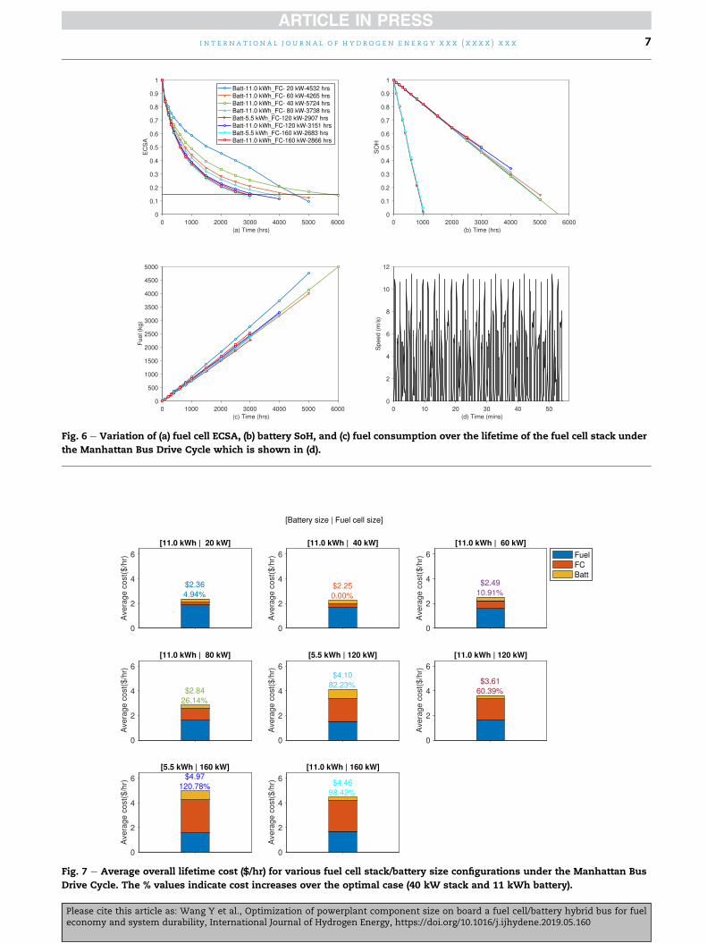
Fig. 6 e Variation of (a) fuel cell ECSA, (b) battery SoH, and (c) fuel consumption over the lifetime of the fuel cell stack under
the Manhattan Bus Drive Cycle which is shown in (d).
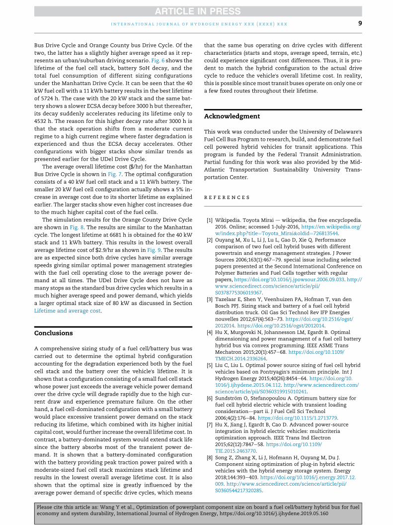
Fig. 7 e Average overall lifetime cost ($/hr) for various fuel cell stack/battery size configurations under the Manhattan Bus
Drive Cycle. The % values indicate cost increases over the optimal case (40 kW stack and 11 kWh battery).
i n t e r n a t i o n a l j o u r n a l o f h y d r o g en en e r g y x x x ( x x x x ) x x x 7
Please cite this article as: Wang Y et al., Optimization of powerplant component size on board a fuel cell/battery hybrid bus for fueleconomy and system durability, International Journal of Hydrogen Energy, https://doi.org/10.1016/j.ijhydene.2019.05.160

Fig. 8 e Variation of (a) fuel cell ECSA, (b) battery SoH, and (c) fuel consumption over the lifetime of the fuel cell stack under
the Orange County Bus Drive Cycle which is shown in (d). (For interpretation of the references to colour in this figure legend,
the reader is referred to the Web version of this article).
Fig. 9 e Average overall lifetime cost ($/hr) for various fuel cell stack/battery size configurations under the Orange County
Bus Drive Cycle. The % values indicate cost increases over the optimal case (40 kW stack and 11 kWh battery). (For
interpretation of the references to colour in this figure legend, the reader is referred to the Web version of this article).
i n t e r n a t i o n a l j o u r n a l o f h y d r o g e n en e r g y x x x ( x x x x ) x x x8
Please cite this article as: Wang Y et al., Optimization of powerplant component size on board a fuel cell/battery hybrid bus for fueleconomy and system durability, International Journal of Hydrogen Energy, https://doi.org/10.1016/j.ijhydene.2019.05.160
i n t e r n a t i o n a l j o u r n a l o f h y d r o g en en e r g y x x x ( x x x x ) x x x 9
Bus Drive Cycle and Orange County bus Drive Cycle. Of the
two, the latter has a slightly higher average speed as it rep-
resents an urban/suburban driving scenario. Fig. 6 shows the
lifetime of the fuel cell stack, battery SoH decay, and the
total fuel consumption of different sizing configurations
under the Manhattan Drive Cycle. It can be seen that the 40
kW fuel cell with a 11 kWh battery results in the best lifetime
of 5724 h. The case with the 20 kW stack and the same bat-
tery shows a slower ECSA decay before 3000 h but thereafter,
its decay suddenly accelerates reducing its lifetime only to
4532 h. The reason for this higher decay rate after 3000 h is
that the stack operation shifts from a moderate current
regime to a high current regime where faster degradation is
experienced and thus the ECSA decay accelerates. Other
configurations with bigger stacks show similar trends as
presented earlier for the UDel Drive Cycle.
The average overall lifetime cost ($/hr) for the Manhattan
Bus Drive Cycle is shown in Fig. 7. The optimal configuration
consists of a 40 kW fuel cell stack and a 11 kWh battery. The
smaller 20 kW fuel cell configuration actually shows a 5% in-
crease in average cost due to its shorter lifetime as explained
earlier. The larger stacks show even higher cost increases due
to the much higher capital cost of the fuel cells.
The simulation results for the Orange County Drive Cycle
are shown in Fig. 8. The results are similar to the Manhattan
cycle. The longest lifetime at 6681 h is obtained for the 40 kW
stack and 11 kWh battery. This results in the lowest overall
average lifetime cost of $2.9/hr as shown in Fig. 9. The results
are as expected since both drive cycles have similar average
speeds giving similar optimal power management strategies
with the fuel cell operating close to the average power de-
mand at all times. The UDel Drive Cycle does not have as
many stops as the standard bus drive cycles which results in a
much higher average speed and power demand, which yields
a larger optimal stack size of 80 kW as discussed in Section
Lifetime and average cost.
Conclusions
A comprehensive sizing study of a fuel cell/battery bus was
carried out to determine the optimal hybrid configuration
accounting for the degradation experienced both by the fuel
cell stack and the battery over the vehicle's lifetime. It is
shown that a configuration consisting of a small fuel cell stack
whose power just exceeds the average vehicle power demand
over the drive cycle will degrade rapidly due to the high cur-
rent draw and experience premature failure. On the other
hand, a fuel cell-dominated configuration with a small battery
would place excessive transient power demand on the stack
reducing its lifetime, which combined with its higher initial
capital cost, would further increase the overall lifetime cost. In
contrast, a battery-dominated system would extend stack life
since the battery absorbs most of the transient power de-
mand. It is shown that a battery-dominated configuration
with the battery providing peak traction power paired with a
moderate-sized fuel cell stack maximizes stack lifetime and
results in the lowest overall average lifetime cost. It is also
shown that the optimal size is greatly influenced by the
average power demand of specific drive cycles, which means
Please cite this article as: Wang Y et al., Optimization of powerplanteconomy and system durability, International Journal of Hydrogen E
that the same bus operating on drive cycles with different
characteristics (starts and stops, average speed, terrain, etc.)
could experience significant cost differences. Thus, it is pru-
dent to match the hybrid configuration to the actual drive
cycle to reduce the vehicle's overall lifetime cost. In reality,
this is possible sincemost transit buses operate on only one or
a few fixed routes throughout their lifetime.
Acknowledgment
This work was conducted under the University of Delaware'sFuel Cell Bus Program to research, build, and demonstrate fuel
cell powered hybrid vehicles for transit applications. This
program is funded by the Federal Transit Administration.
Partial funding for this work was also provided by the Mid-
Atlantic Transportation Sustainability University Trans-
portation Center.
r e f e r e n c e s
[1] Wikipedia. Toyota Mirai d wikipedia, the free encyclopedia.2016. Online; accessed 1-July-2016, https://en.wikipedia.org/w/index.php?title¼Toyota_Mirai&oldid¼726813544.
[2] Ouyang M, Xu L, Li J, Lu L, Gao D, Xie Q. Performancecomparison of two fuel cell hybrid buses with differentpowertrain and energy management strategies. J PowerSources 2006;163(1):467e79. special issue including selectedpapers presented at the Second International Conference onPolymer Batteries and Fuel Cells together with regularpapers, https://doi.org/10.1016/j.jpowsour.2006.09.033. http://www.sciencedirect.com/science/article/pii/S0378775306019367.
[3] Tazelaar E, Shen Y, Veenhuizen PA, Hofman T, van denBosch PPJ. Sizing stack and battery of a fuel cell hybriddistribution truck. Oil Gas Sci Technol Rev IFP Energiesnouvelles 2012;67(4):563e73. https://doi.org/10.2516/ogst/2012014. https://doi.org/10.2516/ogst/2012014.
[4] Hu X, Murgovski N, Johannesson LM, Egardt B. Optimaldimensioning and power management of a fuel cell batteryhybrid bus via convex programming. IEEE ASME TransMechatron 2015;20(1):457e68. https://doi.org/10.1109/TMECH.2014.2336264.
[5] Liu C, Liu L. Optimal power source sizing of fuel cell hybridvehicles based on Pontryagin's minimum principle. Int JHydrogen Energy 2015;40(26):8454e64. https://doi.org/10.1016/j.ijhydene.2015.04.112. http://www.sciencedirect.com/science/article/pii/S0360319915010241.
[6] Sundstr€om O, Stefanopoulou A. Optimum battery size forfuel cell hybrid electric vehicle with transient loadingconsiderationdpart ii. J Fuel Cell Sci Technol2006;4(2):176e84. https://doi.org/10.1115/1.2713779.
[7] Hu X, Jiang J, Egardt B, Cao D. Advanced power-sourceintegration in hybrid electric vehicles: multicriteriaoptimization approach. IEEE Trans Ind Electron2015;62(12):7847e58. https://doi.org/10.1109/TIE.2015.2463770.
[8] Song Z, Zhang X, Li J, Hofmann H, Ouyang M, Du J.Component sizing optimization of plug-in hybrid electricvehicles with the hybrid energy storage system. Energy2018;144:393e403. https://doi.org/10.1016/j.energy.2017.12.009. http://www.sciencedirect.com/science/article/pii/S0360544217320285.
component size on board a fuel cell/battery hybrid bus for fuelnergy, https://doi.org/10.1016/j.ijhydene.2019.05.160

i n t e r n a t i o n a l j o u r n a l o f h y d r o g e n en e r g y x x x ( x x x x ) x x x10
[9] Wang Y, Moura SJ, Advani SG, Prasad AK. Powermanagement system for a fuel cell/battery hybrid vehicleincorporating fuel cell and battery degradation. Int JHydrogen Energy 2019;44(16):8479e92. https://doi.org/10.1016/j.ijhydene.2019.02.003. http://www.sciencedirect.com/science/article/pii/S0360319919305014.
[10] Hu Z, Li J, Xu L, Song Z, Fang C, Ouyang M, Dou G, Kou G.Multi-objective energy management optimization andparameter sizing for proton exchange membrane hybrid fuelcell vehicles. Energy Convers Manag 2016;129:108e21.https://doi.org/10.1016/j.enconman.2016.09.082. http://www.sciencedirect.com/science/article/pii/S0196890416308871.
[11] Bubna P, Brunner D, Gangloff Jr JJ, Advani SG, Prasad AK.Analysis, operation and maintenance of a fuel cell/batteryseries-hybrid bus for urban transit applications. J PowerSources 2010;195(12):3939e49. https://doi.org/10.1016/j.jpowsour.2009.12.080. http://www.sciencedirect.com/science/article/pii/S0378775309023428.
[12] Bubna P, Brunner D, Advani SG, Prasad AK. Prediction-basedoptimal power management in a fuel cell/battery plug-inhybrid vehicle. J Power Sources 2010;195(19):6699e708.
Please cite this article as: Wang Y et al., Optimization of powerplaneconomy and system durability, International Journal of Hydrogen E
https://doi.org/10.1016/j.jpowsour.2010.04.008. http://www.sciencedirect.com/science/article/pii/S0378775310005896.
[13] DOE. DOE technical targets for hydrogen production fromelectrolysis. 2011. https://www.energy.gov/eere/fuelcells/doe-technical-targets-hydrogen-production-electrolysis.
[14] DOE. DOE technical targets for fuel cell systems and stacksfor transportation applications. 2015. https://energy.gov/eere/fuelcells/doe-technical-targets-fuel-cell-systems-and-stacks-transportation-applications.
[15] Pei P, Chang Q, Tang T. A quick evaluating method forautomotive fuel cell lifetime. Int J Hydrogen Energy2008;33(14):3829e36. tMS07: Symposium on Materials inClean Power Systems, https://doi.org/10.1016/j.ijhydene.2008.04.048. http://www.sciencedirect.com/science/article/pii/S036031990800476X.
[16] DOE. Overview of the DOE VTO advanced battery RDprogram. 2016. https://energy.gov/sites/prod/files/2016/06/f32/es000_howell_2016_o_web.pdf.
[17] NREL. Fuel cell buses in u.s. transit fleets: current status 2017.2017. https://www.osti.gov/biblio/1410409.
t component size on board a fuel cell/battery hybrid bus for fuelnergy, https://doi.org/10.1016/j.ijhydene.2019.05.160