optimization of tcf-5 and tjf composite free form
TRANSCRIPT

ADVANCES IN MANUFACTURING SCIENCE AND TECHNOLOGY Vol. 36, No. 3, 2012
10.2478/v10264-012-0018-z
Address: Wojciech ZĘBALA, DSc. Eng., Andrzej MATRAS, PhD Eng., Robert KOWALCZYK, MSc. Eng., Cracow University of Technology, Production Engineering Institute, al. Jana Pawła II 37, 31-864 Cracow, e-mail: [email protected]
OPTIMIZATION OF TCF-5 AND TJF COMPOSITE FREE FORM SURFACE MILLING
Wojciech Zębala, Andrzej Matras, Robert Kowalczyk
S u m m a r y
Paper presents researches of fibre-matrix composite materials machining on the turbine blade example. The main aim of investigations was the free form milling process and its optimization considering the machined surface quality. TCF-5 and TJF composite types were chosen. Different strategy and cutting parameters were applied. The profile of the work piece was obtained as a result of scanning process of the real surface, using a spatial actual scanner CYCLONE 2 manufactured by Renishaw company.
Keywords: Composites, milling, free-form surface, optimization
Optymalizacja procesu frezowania powierzchni swobodnych kompozytu TCF-5 i TJF
S t r e s z c z e n i e
W artykule przedstawiono analizę wyników badań obróbki włóknistych materiałów kompozytowych TCF5 i TJF na przykładzie łopatki turbiny. Prowadzono proces frezowania powierzchni swobodnej. Wykonano jego optymalizację, przyjmując kryterium jakości powierzchni obrobionej TCF-5 i TJF. Zastosowano różne strategie i wartości parametrów skrawania. Profil elementu obrabianego uzyskano przez skanowanie rzeczywistej powierzchni przy użyciu skanera CYCLONE 2 firmy Renishaw.
Słowa kluczowe: Kompozyty, frezowanie, powierzchnia swobodna, optymalizacja
1. Introduction
In recent years, manufacturing technology of composites and their machining are developed on a great scale. It is due to the fact, that the composites combine steel and plastic materials properties. Basic physical features of composites are high strength and low weight. These constructional materials are mainly used in automotive and aerospace industries.
During machining of fibre-matrix composites unfavourable phenomena occurs, which leads to destruction of the work piece or inability to the proper quality obtainment of free surface after the machining process [1-5].
30 W. Zębala, A. Matras, R. Kowalczyk
The aim of described investigations is the optimization (surface quality criterion) of the free surface milling process of work piece made of fibre-matrix composites (TCF-5 and TJF).
2. Basic information about composites
The composite material is composed of two or more components of different properties. One of the components is a matrix which bonds the whole of the composite group and assigns it hardness, flexibility and resistance to pressure. The second composite’s component is a constructional material (supportive material) which is responsible for the composite strengthening.
The role of the matrix is to protect the supportive material, transfer of external stresses to supportive material and create the desired shape of manufactured part of the composite. The function of the supportive material is holding of the appropriate mechanical properties and strengthening of the matrix in selective directions [2, 3].
The reinforced composites with fibres are used in order to provide increased static and fatigue strength due to reliable and rigid fibres. The matrix usually is brittle or soft and malleable, which moves the applied load to the fibres. The composites reinforced with fibres have high strength properties in high temperature conditions [1]. Fibres reinforced composites are usually used in the form of laminates, made by bonding two or more parts together. Lamina usually is made of parallel fibres set in a polymer matrix at some constant volume fraction. The laminate is assembled with the individual lamina at different fibre orientations [3]. Composites can be classified in different ways [1]:
1. The classification due to the material of the matrix • OMCs (organic-matrix composites)
− PMCS (polymer-matrix composites) − CCCs (carbon-matrix composites)
• MMCs (metal-matrix composites) • IMCS (intermetallic-matrix composites) • CMCs (ceramic-matrix composites)
2. The classification due to the material of the supportive • The composites reinforced with solid particles
− Reinforced of dispersion − Large particles
• The composites reinforced with fibres − Filament fibres − Woven fabrics

Optimization of TCF-5 and TJF composite ... 31
− Discontinuous fibre Oriented Random distributions • The structure of composites
− Laminated − The core of the light material
Figure 1 presents the examples of cross-section views of elements with reinforced composites. Types and characteristic of matrix and supportive materials are shown in Table 1.
Fig. 1. Cross-sections of composite [3]
Table 1. Types and characteristic of matrix and supportive materials [1, 3]
Kind of phase Kind of material Characteristic
Matrix
Hardenable polymers
Epoxides, polyester, phenol formaldehyde resin, fluoride and carbon materials, polyamide
Thermo-plastic polymers
Polieteroketon is more ductile than the hardening plastics but with less resistance to temperature
Metals Aluminium and aluminium alloys-lithium, magnesium, titanium
Ceramics Silicon carbide, silicon nitride, aluminium oxide and mullite
Fibres and other hardenable
elements
Glass High strength, low stiffness, high density, low cost, used glass type E (borosilicate safety) and S (magnesium-aluminium-silicate)
Carbon Available as characterized by high module of elasticity or high strength, low cost, less density than glass
Boron High strength and stiffness, the highest density, the highest cost, tungsten fibre exist inside
Armidas The largest strength of all fibres, high cost
Other fibres Polyamide, silicon carbide, silicon nitride, aluminium oxide, boron carbide, boron nitride, tantalum carbide, steel, tungsten, molybdenum

32 W. Zębala, A. Matras, R. Kowalczyk
In industry and laboratories parts used for female mould matrix with free surfaces are manufactured by pressing the composite or machining process [1, 3, 6, 7], Fig. 2-3. Machining is used for finishing-process.
Fig. 2. The diagram of super plasticity process of deformation and diffusion bonding of the blade with Ti-SiC composite [1]
Fig. 3. The schema for hot deformation in closed matrix and diffusion bonding on several monolithic boards for the
manufacture of blades with Ti-SiC composite [1]

Optimization of TCF-5 and TJF composite ... 33
3. Machining of free form surface of blade made of TCF-5 and TJF composite
The work piece discussed in this contribution is a part of a turbine engine blade, which external surfaces have irregular profiles. The work piece is made of TCF-5 and TJF fibre-matrix composite, which physical and mechanical properties are set out in Table 2.
The profiles of the work pieces were obtained in the scanning process of the turbine engine blade surface, using a spatial actual scanner CYCLONE 2 by manufactured by of Renishaw company.
A cloud of points, obtained in the scanning process was transformed into CAD model in CAD/CAM software Catia V5, Fig. 4-5.
Fig. 4. The cloud of points after scanning process
Fig. 5. The model of the work piece in the environment of CAD/CAM Catia V5
The TCF-5 fibre-matrix composite is a laminar material obtained in pressuring process at elevated temperature consisting on several-dozen layers of

34 W. Zębala, A. Matras, R. Kowalczyk
cotton fabric saturated with the phenol resin. The TJF fibre-matrix composite is a board made of the phenol resin and jute fibres.
The TCF-5 and TJF fibre-matrix composite can be used at temperatures up to 120oC, work in oily environment and normal humidity atmosphere [8].
Characterization and properties of TCF and TJF textolit [8]: • Used for production of elements of bearings and sliding sleeve, rolling
bearing cages, sealing rings, guides, elements of roller and race tracks, the wheels and the wheels rim gears, cams and other elements of construction,
• High-pressure TCF laminate is enriched with cotton fibres stable mechanical properties in a wide range of temperatures. TJF is enriched with jute fibres,
• Produced according to PN-EN 60893, DIN 7735, NEMA L-1 standards, • High static and dynamic strength, • High resistance to creep and dimensional stability, • Low coefficient of friction and low grindability, • Self-lubricating, self-lapping, • Ability of vibration damping and silent-running, • Resistance to chemicals, • Low specific gravity, • Property of electrical insulating.
Table 2. Physical properties of TCF-5 and TJF fibre-matrix composites [8,9]
Properties J.m. TCF-5 and TJF
Density kg/m3 1.3-1.5 Bending stress of fracture in temp. 20oC MPa 100 Module of elasticity MPa 7x10³
Tensile stress MPa 80 Shear stress perpendicular to layers MPa 25 Impact strength, at least an – 15 perpendicular to the layers ak – 10 parallel to layers
kJ/m2
kJ/m2 30 9
Absorbability of the water mg 249 Operating temperature range [9] oC -40÷100 Electric strength [9] kV/mm 5
The appropriate milling parameters of fibre-matrix composites TCF-5 and
TJF have been identified on the basis of analysis of sample surfaces after machining with the ball nose milling tool. During the tests various directions of machining (Fig. 6) and various values of feed rate were verified.

Optimization of TCF-5 and TJF composite ... 35
Fig. 6. Directions of the milling tool paths in relation to the fibres location in the composite
a) b)
Fig. 7. Results of measurements: a) the influence of milling direction, feed and kind of composite materials on the value of roughness parameter Sa (Average Roughness), b) the isometric view and the profile of the composite surface TJF for fz = 0.12 mm
a) b)
Sa, μm

36 W. Zębala, A. Matras, R. Kowalczyk
Fig. 8. Results of measurements: a) the influence of the milling direction, feed and kind of composite materials on the value of roughness parameter Sz (Peak-Peak), b) the isometric view and the profile of the composite surface TCF-5 for fz = 0.06 mm
Machining was carried out with use of the double cutting edge ball nose tool with a 6 mm diameter. Three values of feed rate were established as follows: fz1 = 0.06, fz2 = 0.09 and fz3 = 0.12 mm tooth. The tests were carried out at a constant cutting speed: vc = 110 m/min.
After machining surfaces were measured on profilographometer TalySurf Intra 50 and parameters of roughness 2D and 3D were determined. The results of measurements for different strategy of machining and composite materials are presented in Fig. 7-8. Diagrams on the left side show the minimum and maximum values of selected 3D surface roughness parameters, while the right side of the figures show isometric views of the surface topography, maps of the surface waviness and roughness profiles for the selected strategy of composite machining.
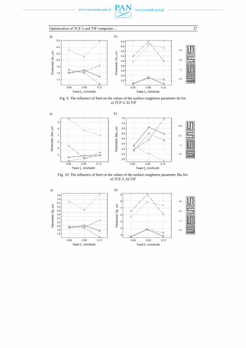
Figures 9-12 show the influence of feed on the values of selected 3D parameters of the surface roughness (Sa, Sku, Sq, Sz).
Sa, μm
Optimization of TCF-5 and TJF composite ... 37
Fig. 9. The influence of feed on the values of the surface roughness parameter Sa for: a) TCF-5, b) TJF
Fig. 10. The influence of feed on the values of the surface roughness parameter Sku for: a) TCF-5, b) TJF

38 W. Zębala, A. Matras, R. Kowalczyk
Fig. 11. The influence of feed on the values of the surface roughness parameter Sq for: a) TCF-5, b) TJF
Fig. 12. The influence of feed on the values of the surface roughness parameter Sz for: a) TCF-5, b) TJF
It can be observed that most of roughness parameters have lower values for bigger feed rates. Basing on the CAM Esprit software an example part with free form surfaces was prepared. Tool path for rough and finish machining were defined (Fig. 13-14).
Machining of the constructed part was performed for feed fz = 0,12 mm and direction of tool movement crosswise to the laminates surface (Fig. 15). Isometric views of roughness, waviness and the Abbott-Firestona curves for the received surface are shown in Fig. 16-17. In Figure 18 the microscopic photos of machined parts (blades) made of composites TCF-5 and TJF are presented.
Fig. 13. The tool path for rough machining

Optimization of TCF-5 and TJF composite ... 39
Fig. 14. The tool path for finish machining
a) b)
Fig. 15. The photos of machined parts (blades) made of composite: a) TCF-5, b) TJF. Squares show the area of surface roughness measurements
a) b)

40 W. Zębala, A. Matras, R. Kowalczyk
Fig. 16. The isometric views of surface roughness of blades made of composites: a) TCF-5, b) TJF
a) b)
Fig. 17. The isometric views of surface waviness of blades made of composites: a) TCF-5, b) TJF
a) b)
Fig. 18. The micro-structure surface of the blade made of composite: a) TCF-5, b) TJF
The average values of selected 3D roughness parameters are shown in
Fig. 19.
500 μm 500 μm

Optimization of TCF-5 and TJF composite ... 41
Fig. 19. The average values of selected 3D roughness parameters
4. Conclusions
The investigations described in this study indicate that the cutting parameters (cutting speed, feed) and direction of machining to laminate’s surface influence on the surface roughness of parts made of TCF-5 and TJF composites. After proper cutting parameters selection (feed fz = 0.12 mm, vc = 110 m/min) the example parts with free form surface were machined. At all feed and milling strategy surface roughness parameters decrease their values as feed increases.
Acknowledgement
This publication was made in the frame of Hungarian – Polish Intergovernmental S&T Cooperation Programme signed PL-7/2009 (Contract number: TÉT_10-1-2011-0016), financially supported by NDA and its foreign contractual partner.
References
[1] L.A. DOBRZAŃSKI: Podstawy nauki o materiałach i metaloznawstwo. Materiały inżynierskie z podstawami projektowania materiałowego. WNT, Warszawa 2002.
[2] K.E. OCZOŚ: Kompozyty włókniste – właściwości, zastosowanie, obróbka ubytkowa. Mechanik, 7(2008), 579-580.
[3] A. VIJAYARAGHAVAN: Drilling of Fiber-Reinforced Plastics. Tool Modeling and Defect Prediction. Master’s Report, University of California, Berkeley 2005.
Para
met
ers
Sa, S
ku, S
q, μ
m
Para
met
er S
z, μ
m
Sa Sku Sq Sz

42 W. Zębala, A. Matras, R. Kowalczyk
[4] M.N. CHENG, C.F. CHEUNG, W.B. LEE, S. TO, L.B. KONG: Theoretical and experimental analysis of nano-surface generation in ultra-precision raster milling. Inter. Journal of Machine Tools & Manufacture, 48(2008), 1090-1102.
[5] Ming-Yung WANG, Hung-Yen CHANG: Experimental study of surface roughness in slot end milling Al2014-T6. Inter. Journal of Machine Tools & Manufacture, 44(2004), 51-57.
[6] M.S. KARAKAS, et.al.: Effect of cutting speed on tool performance in milling of B4Cp reinforced aluminium metal matrix composites. Journal of Materials Processing Technology, 178(2006), 241-246.
[7] N.S.K. REDDY, P. Rao VENKATESWARA: Selection of optimum tool geometry and cutting conditions using a surface roughness prediction model for end milling. Inter. Journal of Advanced Manufacturing Technology, 26(2005), 1202-1210.
[8] www.tekstolit.com. [9] www.distrelec.com.
Received in April 2012