optimized design of an electrostatic side-drive micromotor · optimized design of an electrostatic...
TRANSCRIPT
OPTIMIZED DESIGN OF AN ELECTROSTATIC SIDE-DRIVE MICROMOTOR Humberto Ferreira Vinhais Escola Politécnica da Universidade de São Paulo Av. Prof. Mello de Moraes, 2231, São Paulo –SP – 05508-900 [email protected] Paulo Henrique de Godoy Escola Politécnica da Universidade de São Paulo Av. Prof. Mello de Moraes, 2231, São Paulo –SP – 05508-900 [email protected]
Emilio Carlos Nelli Silva Escola Politécnica da Universidade de São Paulo Av. Prof. Mello de Moraes, 2231, São Paulo –SP – 05508-900 [email protected] Abstracts. Recently, electrostatic motors have gained a new international perspective with the technology of micro-manufacturing of MEMS (Micro-Electromechanical systems). The micromotors have becoming more popular in scientific research in diverse fields of engineering: as the development of high-quality scanners, micro-optical switches for fiber-optic networks, new endoscopes for invasive surgeries with larger viewing scopes, etc. An electrostatic side-drive motor is essentially driven by electrostatic forces: the induced electric loads in the rotor are attracted by electric loads of the stator, generating an electrostatic force which creates a mechanical torque in the rotor of the micro-motor. Even though, plenty of work was developed related to the manufacturing of the micromotors, there are only a few studies in literature about their design using computational and mathematical approaches. Thus, in this work optimization techniques are applied to obtain the optimized topology of the electrostatic micromotor rotor aiming to maximize its final torque. This work is divided in three different steps towards the optimized design of an electrostatic side-drive micromotor: computational simulations using the Finite Element Method (FEM), through commercial software ANSYS to analyze the influence of the design variables in the final torque; microfabrication of LIGA-like micromotor prototypes using photolithography and electrodeposition (with assistance of LNLS); and the development of an optimized design of an electrostatic side-drive micromotor applied to MEMS using Topology Optimization Method (TOM) to maximize the rotor mutual energy and, consequently, its torque. Keywords. electrostatic side-drive micromotor, MEMS, topology optimization, computational simulation, LIGA-like fabrication
1. Introduction
The electrostatic motors had been the first electric motors developed in history. The first electrostatic motor was
developed in 1742 (Tai, 1995). These motors had not attracted scientific interest until 1980, when they begun to be manufactured in micro-scale. With the development of new micro-manufacturing techniques and with the widespread use of MEMS ("Microelectromechnical Systems"), great opportunities for the electrostatic micromotors had been opened. Recently, in July of 2003, University of California developed the smallest motor of the world, an electrostatic micromotor of 500 nanometers, 300 times lesser than the diameter of a human hair.
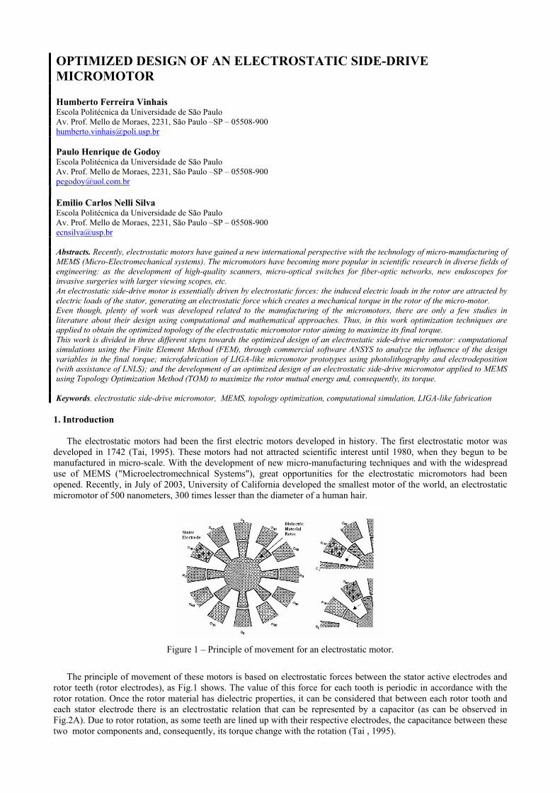
Figure 1 – Principle of movement for an electrostatic motor.
The principle of movement of these motors is based on electrostatic forces between the stator active electrodes and
rotor teeth (rotor electrodes), as Fig.1 shows. The value of this force for each tooth is periodic in accordance with the rotor rotation. Once the rotor material has dielectric properties, it can be considered that between each rotor tooth and each stator electrode there is an electrostatic relation that can be represented by a capacitor (as can be observed in Fig.2A). Due to rotor rotation, as some teeth are lined up with their respective electrodes, the capacitance between these two motor components and, consequently, its torque change with the rotation (Tai , 1995).

In Figure 2, some electrostatic motor types, found in literature, are presented (A, B, C and D). These electrostatic motors also are called salient-pole motors and step motors. According to its nomenclature, the motor A is a 6:8 motor, because it has 6 electrodes in the stator and 8 teeth in the rotor. In the same way, motor B and D are 12:8 motors and motor C is an 18:6 motor.
Figure 2 – Few examples of some micromotors found in literature.
Researches for micromotors are expanding in different fields of Engineering (Yasseen,, 1999): as in the
development of diffraction grating microscanners with high precision (Fig.2B); optical switches for fiber optic nets (Fig.2D), etc.
MEMS has being widely used in diverse fields of research, as Engineering and Medicine, for development of microsensors and microactuators (Lefèvre, 1995). Researches in this area have growing more and more, making possible the widespread use of new micromanufacturing technologies, justifying the current interest increase for this area.
Many methods for designing micromotors are reported in literature, however, the vast majority of them only focus the manufacturing or the computational simulation, using analytical methods or the Finite Element Method (FEM), without presenting a systematic approach to optimize the design of these micromotors. Due to this aspect, many devices still have been designed by intuition or experience. Therefore, systematic design methods, such as the topology optimization, have much to contribute to considerably improve the existing micromotor designs, as well as developing new and more efficient devices, or devices that could do different tasks in different applications.
The general topology optimization problem consists in distributing a given amount of material in a design domain subjected to load and support conditions to maximize or minimize a specified function, as, for example, the stiffness of the structure.
Thus, this work intends to design an optimized electrostatic micromotor and it can be divided in three perspectives: computational simulation of a micromotor model using Finite Element Method (FEM) through commercial software ANSYS, to analyze the influence of the motor design parameters in its final torque; micro-manufacturing of 12:8 electrostatic micromotor prototypes, using UV photolithography techniques and metal electroplating with the assistance of the Microfabrication Laboratory of LNLS (Laboratório Nacional Luz Síncroton) in Campinas (SP); and the development of an optimization software to design the rotor of a 16:4 micromotor using the Topology Optimization Method (TOM), which is the main purpose of this work.
In this sense, this work is an innovative project in the national scope, once no work was found in Brazil that deals with systematic and optimized design of electrostatic micromotors, together with its computational simulation and micromanufacturing of prototypes. 3. Electrostatic FEM
To implement the electrostatic micromotor optimization, it is necessary to understand the electrostatic FEM
equations, which will be implemented in the optimization software. To solve an electrostatic nature problem, it is considered that the electrostatic field must satisfy the following
Maxwell equations (Bathe, 1982):
∇× =E 0 ; ρ∇ ⋅ =D (1)
where ×∇ is the rotational operator, ⋅∇ is the divergent operator, E is the electric field vector, D is the vector of electrical displacement and ρ is the free electric load.
From another constitutive relation for electric fields, we have:
=D εE
A B C D

(2) where ε is the electrical permissivity matrix.
Using the previous expressions, a solution for the mathematical problem can be obtained by introducing the electric potential variable, which allows us to express the electric field by:
V= −∇E (3)
Thus, solving the Maxwell equation . ρ∇D = and the constitutive equation D = εE , Eq.(4) can be obtained:
( )Vε ρ−∇ ⋅ ∇ = (4) Once the electric potential V is the degree of freedom, considering N as the shape function matrix, the voltage V can
be expressed as:
= TeV N V (5)
where N is the element interpolation function and Ve is the nodal electric potential vector.
Considering the discretization of the domain, the electric behavior in each electrostatic finite element is expressed by (Bathe, 1982):
ee e e iK V = Q Q+ ; C SC= +e e eQ Q Q (6)
where eiQ is the internal electric load vector, Qe is the electric load vector of the problem, CeQ is the electric load
vector applied to the element and SCeQ is the electric load vector defined for the element surface and Ke is the electric
stiffness matrix of this finite element problem given by:
( ) ( )1 1
1 1
detTT T
eh d dε ξ η− −
= ∇ ∇∫ ∫eK N N J (7)
where he is the thickness of the element (considered bidimensional) and detJ is the jacobian matrix determinant. 4. Topology Optimization applied to design a micromotor
Topology Optimization consists in a computational method that allows us to design the optimum topology of
structures under certain cost criterion (for example, maximum rigidity and minimum weight). Essentially, the objective of topology optimization method is to distribute material inside a fixed domain to maximize or minimize a specified function. The material in each point of the domain can vary from air (which does not have material presence) to solid (total presence of material) being able to assume intermediate densities between air and solid (Byun, 2002).
Figure 3 – Example of the TOM procedure applied to the design of an electrostatic micromotor.
Therefore, having the fixed domain divided into finite elements (through FEM), we can associate a value of density within each element based on the material distribution in the domain. Thus, this distribution of densities given by the optimization algorithm (as shown in the figure above) can be interpreted to obtain the final rotor design.
The material model is an equation that defines the mixture, in micro-scale, of two or more materials (one of them can be air) allowing intermediate values of material density between zero ("hole", 0 value) and solid (1 value) in any region of the domain. This prevents a sudden change in density from air to solid, which makes the problem ill-posed. There are many material models described in the literature that could be used. The simplest one is called density method (Bendsoe, 2003). It consists in a mathematical equation that defines the density value in each point of the domain in function of the used material property.

In this work, the main objective is to fill the region of the rotor with dielectric material (Byun, 2002), as it is shown in the Fig.4A below.
Figure 4 – (A) Design domain of the micromotor for TOM and (B) Rotor rotation from reference point A to B
In this work, the following expression is used for material model:
( )( )0 1 1 n
i r iε ε ε ρ= + − , ( )0 1, 2 4nρ≤ ≤ ≤ ≤ (8)
where ε0 is the air permissivity, εr is the relative permissivity of the dielectric material and n is the penalization factor that penalizes intermediate values of density, or either, values different from 0 or 1.
Thus, to generate maximum torque during the micromotor operation, it is necessary to maximize the difference of the whole system energy when the rotor passes from position A to position B, as Fig. 4B shows for a 16:4 micromotor (Byun, 2002).
Thus, the objective function that is supposed to be maximized can be defined as (Byun, 2002):
( )22
0
1
2 A B BF W W W= + − (9)
where F is the objective function, WA and WB are the total system energies for the positions A and B, respectively, and WB0 is the maximum possible system energy in position B, or either, the computed energy when all the region of the rotor is filled with dielectric material. 5. Micromotor microfabrication
The micromanufacturing process used in this work is schematized in Fig. 5 and Fig. 6. This process makes use of photo-lithography techniques for UV exposition and metal electroplating, which is available in the Micro-fabrication Laboratory of LNLS and also applied in many works described in literature (Chien-Hung, 2002).
As it can be seen in Fig. 5, there are essentially 9 stages that compose the process of micromanufacturing of the electric track together with the axle/stator set and 7 stages that compose the manufacturing of the micromotor rotor. Actually, the manufacturing of each component of the micromotor can be interpreted together by presenting some similar stages, as it will be seen in this article.
Figure 5 - Transversal section of the electric track structure and the axle/stator set during the manufacturing process.
(A) (B)

The first stage (shown in Fig. 5A) is the preparation of the substrate. In the second stage (shown in Fig. 5B), is the
deposition of the seed layer (as it is called in literature). This layer is common in micromanufacturing processes and is this layer that allows the electroplating and improves the adhesion of some metals to the substrate. In this work, this layer is composed by 200 angstroms of titanium and 600 angstroms of gold.
The third stage (shown in Fig. 5C) corresponds to the mold deposition of the photoresist using the photolithography technique with UV exposition (Chien-Hung, 2002). In this case, the application of photoresist aims to create a mold for the electric track electroplating, using AZ-4620 as the molding material (which is a positive photoresist) with 10 micra thickness. In the fourth stage (shown in Fig. 5D), the electroplating occurs. The figure shows the growth (electroplating) of the electric track structure. However, this occurs similarly for the axle/stator set and for the rotor. This structure grows inside of the photoresist mold and, for the electroplating, gold is used, with a height less than 10 micra. In the fifth stage (shown in Fig. 5E), the photoresist mold is removed by using acetone.
In the sixth stage (shown in Fig. 5F), deposition of the structure of the micromotor axle and its stator is started. The same structure where the electric track was manufactured is used in the manufacturing of the axle/stator set, so this overlaps the track in the same substrate plate. Thus, the photoresist of the axle/stator set is applied. For this case, the photoresist used was SU-8 100 (which is a negative photoresist) with thickness of 60-100 micra. In the following stage, the seventh stage (shown in Fig. 5G), nickel is electroplated inside of the photoresist mold for formation of the axle/stator set. Thus, the stator structure is overlapping the structure of the electric track, guaranteeing electrical contact.
In the eighth stage (shown in Fig. 5H), the photoresist layer is chemically removed using a proper remover, available in the LNLS. In the ninth, and last, stage of the manufacturing of the electric track, axle and stator structures (shown in Fig. 5I), the seed layer is chemically removed to prevent electric contact between the stator, the axle and the surface in which the micromotor rotor is placed. It is important to understand that this layer is, in part, composed by gold and, therefore, during its removal, a small layer of the track surface (also of gold) is removed together. However, this thin removed layer is insignificant for the electrical track final structure.
As it has been already mentioned, the process of rotor manufacturing is similar to the process previously explained. The figure below shows the micromanufacturing of the rotor structure.
Figure 6 - Transversal section of the micromotor rotor structure during the micromanufacturing process.
The first and the second stages of the rotor manufacturing process (shown in Fig. 6A and Fig. 6B) are equal to the
two first stages of the stator manufacturing process. In the third stage (shown in Fig. 6C) a sacrificial copper layer is deposited (using the electroplating technique). This layer is used in micromanufacturing of this rotor structure, however, it is removed in the end of the process, so the rotor could be released from the substrate and could be freely located to rotate in the micromotor final structure. In the fourth stage (shown in Fig. 6D), photoresist is applied to create the rotor mold. In the fifth stage (shown in Fig. 6E), the rotor structure is electroplated on the copper sacrificial layer. In this process of electroplating, nickel is used for the rotor structure. In the following stage, the sixth stage (shown in Fig. 6F), the photoresist is removed with a proper remover, available in the LNLS. At last, in the seventh stage (shown in Fig. 6G), the sacrificial layer is chemically removed and the rotor structure is released. To conclude the construction of the micromotor, the rotor structure is manually placed on the plate which contains the track structures, the axle and the stator of the micromotor.
6. Results
6.1. Computational Simulation
The main objective of FEM simulations of micromotor models was to know the influence of its design parameters in
its final torque. In this work, a 12:8 micromotor was simulated, which, according to the literature, presents larger torque than other models (Chien-Hung, 2002). The considered design parameters are shown in the figure below.

Figure 7 – (A) Possible design variables and (B) Angular overlapping in the maximum misalignment.
Once the analysis of this influence is made using a comparative approach among the simulations results, the motor
parameters used were not considered in micro scale to facilitate the computational calculations. From these simulations, the results shown below variation obtained for each design parameter.
Figure 8 - Simulations results considering: variation of the rotor radius (to the left); variation of gap between rotor and stator (to the center); and variation of the width of rotor teeth and stator electrodes (to the right).
As Figure 8 shows, the micromotor presents larger developed torque for larger rotor radius, smaller gaps between
rotor and stator and larger rotor teeth and stator electrodes width. These results can be justified knowing that the motor force has electrostatic nature. In relation to the rotor radius, although the electric load proximity increases the electrostatic force between two bodies (for example, a smaller radius results in a smaller distance between electric loads, thus, a larger force), a larger radius implies a larger momentum and, then, a larger micromotor final torque. However, in relation to gap variation, its reduction influences to a higher torque value, because of the electric loads proximity.
To analyze the value of the teeth and electrodes width, Fig. 7B must be observed. Since the configuration of the number of stator electrodes and rotor teeth of the simulated motor is 12:8, for any width above 15° for electrodes and teeth (considering that these two elements have the same width in degrees), there is an angular overlapping. This overlapping, in the case of maximum misalignment (situation where the rotor tooth is as far as possible from the stator electrode where the electric voltage is applied), increases the electrostatic forces, as it can be seen in Fig. 8.
6.2. Prototypes obtained by microfabrication
In the design of the prototypes, the conclusions obtained from the computational simulations results and the manufacturing limits of the Microfabrication Laboratory of LNLS were considered. Thus, 64 micromotor models were manufactured considering the permutation of 50 rotors models and 12 stators models.
By using a routine developed in the commercial software MATLAB, the design parameters of these 64 models were used to create an AutoLisp language file (AutoCAD programming and modeling language), to draw the photolithography masks for the micromanufacturing of these micromotor prototypes. These masks are shown in Fig. 9.

Figure 9 – Top view of the micromotor components mask: 50 rotors models (to the left); 12 stators models (in the superior right part); and 4 electric tracks models (in the inferior right part).
The figure below shows the photo of the manufacturing of a stator structure after the application of the photoresist
mold layer (stage represented for Fig. 5F) to the left. It also shows the photo of the manufacturing of the same stator after the nickel electroplating (stage represented for Fig. 5H), in the center, and a complete prototype after the entire micromanufacturing process, to the right.
Figure 10 - Photos of some stages of micromanufacturing of a stator prototype. 6.3. Optimization Results
After the implementation of a C language software which uses the described concepts of FEM and TOM, rotor optimum designs for different volume constraints were obtained.
The figure below shows the process of optimization during 50 iterations, specifying a volume restriction of 50% of the initial volume and initial normalized densities equal to 1. From iteration 1 to 4, the element densities decrease, however rotor designs remain the same. Up to iteration 5, the rotor design starts to modify, tending to the final result in iteration 23, which does not change until the end of the process.
Figure 11 – Rotor design during 50 optimization iterations.

From the same test, the graphics presented in the figure below were obtained. In the rotor volume graphic, after iteration 5, the value of the volume stabilizes itself, which means that the 50% restriction was reached. This is also shown in Fig. 11, where the rotor structure only starts to change after iteration 5. The objective function and volume convergence graphics show that, from iteration 23, their values do not have significant increase, which means that convergence was reached by the software.
Figure 12 - Rotor topology optimization results.
Other volume restrictions can be applied, however the final rotor design is similar to the last design shown in Fig. 11. For example, in the case of volume restriction of 70% of the initial rotor volume, with the same conditions of the previous test, the same results were achieved. 7. Conclusion
In this work, the optimized design of an electrostatic micromotor was studied in three different perspectives of
research: computational simulation and influence of design parameters in the final torque; micromanufacturing of prototypes using UV photolithography techniques and metal electroplating; and rotor design optimization through the Topology Optimization Method in order to obtain a structure that generates maximum torque. All these objectives were concluded successfully.
In the computational simulation, it could be concluded that the torque increases with larger rotor radius, smaller gap between rotor and stator and bigger rotor teeth and stator electrodes width (which means that the angular overlapping between these elements is bigger).
The micromanufacturing of prototypes was successful. The computational simulation conclusions were considered to design prototypes and to manufacture them to obtain a larger torque.
Finally, the process of topology optimization was also successful, resulting in well-defined rotor designs, with good convergence and physically possible for manufacturing. It was also observed that when the volume constraint is reached, the process does not start to change the rotor design. 8. Acknowledgments
The first author is thankful for the support of the FAPESP (Fundação de Amparo à Pesquisa do Estado de São Paulo), through a master scholarship for the development of this work, and the technical support of the LNLS (Laboratório Nacional Luz Síncroton), where all the prototypes were manufactured. 9. References
Bathe, K. J., 1982, “Finite element procedures in Engineering Analysis”, Prentice-Hall, Inc., Englewood Clifs, New Jersey, 07632, USA.
Bendsoe, M. P.; Sigmund, O., 2003, “Topology Optimization – Theory, Methods and Applications”, Springer Ed. Byun, J., Park, I., Hahn, S., 2002, “Topology Optimization of Electrostatic Actuator Using Design Sensitivity”
Transactions on Magnetics IEEE, Vol. 38, No. 2, pp. 1053-1056. Chien-Hung, H.; Kan-Ping, C.; Chii-Rong, Y.; Hsien-Ming, W.; Soon-Lin, C., 2002 ; “Ultrathick SU-8 mold formations
and removal, and its applications to the fabrication of LIGA-like micromotors with embedded roots”; Sensors and Actuators A 102, pp.130-138.
Frangoult, A. G.; Sundaram, K. B., 1994, “Design and fabrication process for elestrostatic side-drive motors”; Journal of Micromech. Microeng. 5 – 1995; University of Florida, Orlando, pp. 11-17, EUA.
Lefèvre, Y., et al., 1995, “First steps towards design, simulation, modeling and fabrication of elestrostatic micromotors”; Sensors and Actuators, pp-645-648.
Tai, Y. C., 1995, “Micromotors”; The Caltech Micromachinig Group, Electrical Engineering, California Institute of Technology; Jounal Of Microelectromechanical Systems, IEEE, pp.8-11.
Yasseen, A. A.; el at.,1999, "Diffraction Grating Scanners Using Polysilicon Micromotors" Journal of Selected Topics in Quantum Electronics, IEEE, Vol. 5, No. 1, pp.75-82.
10. Responsibility notice
The authors are the only responsible for the printed material included in this paper.