optimizing sidewell furnaces through mathematical modelling · the modelling work is complemented...
TRANSCRIPT
Optimizing Sidewell Furnaces through Mathematical Modelling
Yasar Kocaefe1, Rung Tien Bui
2, André Charette
3
1. Research Professor
2. Emeritus Professor
3. Emeritus Professor
University of Quebec at Chicoutimi, Chicoutimi, Quebec, Canada
Corresponding author: [email protected]
Abstract
Energy requirement for aluminum production through recycling is much less compared to the
primary aluminum production, starting from the raw materials. Recycled aluminum is melted in
different types of furnaces. For the recycled beverage cans, sidewell furnaces are commonly
used. These furnaces have a side well (where the name comes from) in addition to the main
chamber. The chips (shreds) are fed to the side well. Melting is carried out through the energy
provided by the metal circulating between the two parts of the furnace. Such furnaces have been
analyzed using various mathematical models to optimize a number of geometrical and
operational parameters. In this article, the modelling tools used for the optimization of the
sidewell furnace will be explained, and the results of a number of cases will be presented.
Keywords: Sidewell furnaces, mathematical modelling, aluminum cans, aluminum re-melting,
aluminum recycling.
1. Introduction
Energy conservation and environmental protection incentives promoted recycling in many areas
in the last few decades. In aluminum industry, recycling always had a strong presence and has
become an important component of the overall production [1-2]. There are many advantages in
recycling: conservation of natural resources, reduction in waste and pollution, lower energy
costs, and consequently lower production costs.
Beverage cans constitute the most important category of recycled material in quantity and
quality in aluminum industry. The cans are shredded and fed to a unit where the oil and paint
are removed by burning off. Then the shreds are melted and treated in various furnaces for alloy
preparation and casting. The recycled alloy composition is not far from what is needed in the
final product. Such a high alloy quality makes the metal treatment easier and cost-effective. The
energy consumption for the production of cans from recycled material is about 5 % of the
energy consumption if the cans are produced starting from the ore (bauxite).
Many different types of furnaces are used for melting and treating the metal. The sidewell
furnaces are commonly used for shred melting. These furnaces consist of two sections: a main
hearth and a side well from which the name “sidewell” is derived (see Figure 1). The liquid
metal circulates between the main hearth and the side well through two arches located in the
wall, called hotwall, separating these two sections. The advantage of sidewell furnaces is to be
able to melt shreds continuously by feeding them into the side well as opposed to conventional
furnaces where the furnace operation has to be stopped in order to feed the charge into the
hearth. There is also an impeller in the side well where the shreds are fed which provides a
quick submergence minimizing the oxidation of aluminum alloy. The main function of the
impeller is the submergence of shreds; however, it also provides some circulation between the
main hearth and the side well through the arches [3]. It is important to position the impeller
Travaux 47, Proceedings of the 36th International ICSOBA Conference, Belem, Brazil, 29 October - 1 November, 2018
1033

properly to maximize this circulation. In some furnaces, there is also a pump in the main hearth
directed towards the inlet arch where the metal enters the side well from the main hearth [3].
The pump increases mixing of the liquid metal in the main hearth as well as the circulation to
the side well.
Figure 1. A schematic diagram of a sidewell furnace.
The combustion chamber provides the heat necessary for maintaining the liquid at a certain
temperature and melting the solids. Usually, regenerative burners are used in sidewell furnaces
to preheat the combustion air. This is important for energy conservation and improved heat
transfer in the combustion chamber. A controller ensures that the liquid metal is maintained at a
certain temperature level and the refractory temperature does not exceed a certain value to
prevent refractory failure. The fuel flow rate is controlled as a function of metal and refractory
temperatures as well as air flow rate. Even though a vast literature is available on furnaces in
general, publications on sidewell furnaces are limited [3-11].
It is important for the recycling industry to lower the cost and to increase the productivity.
Sidewell furnaces are an important part of the recycling plants, and their operation has to be
improved. A project was undertaken to develop modelling tools for this purpose. The modelling
work is complemented by physical modelling and plant trials for model validation and testing.
2. Mathematical Modelling of Sidewell Furnaces
A sidewell furnace consists of a side well and a main hearth which includes the combustion
chamber. From the mathematical modelling point of view, it is better to divide it into two parts
as follows: liquid metal bath and combustion chamber. Liquid metal bath covers the metal in
both the side well and the main hearth. These two parts have completely different properties
(physical, thermodynamic, etc.), and it is much easier to model them separately. The modular
approach is very important in modelling. Separate models were built for the liquid metal and the
combustion chamber. Then they were coupled through an interface located at the surface of the
metal bath in the main hearth. The modular modelling also has a great advantage if only one
part of the system is to be studied. The model of interest can be used exclusively by imposing
appropriate boundary conditions on the surface where the interface is located. In this project,
different models were developed to study different aspects of sidewell furnaces.
Different modes of heat transfer are important in different sections of the furnace (see Figure 2).
Travaux 47, Proceedings of the 36th International ICSOBA Conference, Belem, Brazil, 29 October - 1 November, 2018
1034
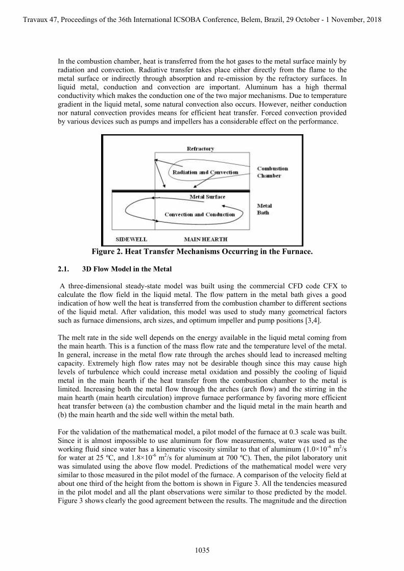
In the combustion chamber, heat is transferred from the hot gases to the metal surface mainly by
radiation and convection. Radiative transfer takes place either directly from the flame to the
metal surface or indirectly through absorption and re-emission by the refractory surfaces. In
liquid metal, conduction and convection are important. Aluminum has a high thermal
conductivity which makes the conduction one of the two major mechanisms. Due to temperature
gradient in the liquid metal, some natural convection also occurs. However, neither conduction
nor natural convection provides means for efficient heat transfer. Forced convection provided
by various devices such as pumps and impellers has a considerable effect on the performance.
Figure 2. Heat Transfer Mechanisms Occurring in the Furnace.
2.1. 3D Flow Model in the Metal
A three-dimensional steady-state model was built using the commercial CFD code CFX to
calculate the flow field in the liquid metal. The flow pattern in the metal bath gives a good
indication of how well the heat is transferred from the combustion chamber to different sections
of the liquid metal. After validation, this model was used to study many geometrical factors
such as furnace dimensions, arch sizes, and optimum impeller and pump positions [3,4].
The melt rate in the side well depends on the energy available in the liquid metal coming from
the main hearth. This is a function of the mass flow rate and the temperature level of the metal.
In general, increase in the metal flow rate through the arches should lead to increased melting
capacity. Extremely high flow rates may not be desirable though since this may cause high
levels of turbulence which could increase metal oxidation and possibly the cooling of liquid
metal in the main hearth if the heat transfer from the combustion chamber to the metal is
limited. Increasing both the metal flow through the arches (arch flow) and the stirring in the
main hearth (main hearth circulation) improve furnace performance by favoring more efficient
heat transfer between (a) the combustion chamber and the liquid metal in the main hearth and
(b) the main hearth and the side well within the metal bath.
For the validation of the mathematical model, a pilot model of the furnace at 0.3 scale was built.
Since it is almost impossible to use aluminum for flow measurements, water was used as the
working fluid since water has a kinematic viscosity similar to that of aluminum (1.0×10⁻⁶
m2/s
for water at 25 ºC, and 1.8×10⁻⁶
m2/s for aluminum at 700 ºC). Then, the pilot laboratory unit
was simulated using the above flow model. Predictions of the mathematical model were very
similar to those measured in the pilot model of the furnace. A comparison of the velocity field at
about one third of the height from the bottom is shown in Figure 3. All the tendencies measured
in the pilot model and all the plant observations were similar to those predicted by the model.
Figure 3 shows clearly the good agreement between the results. The magnitude and the direction
Travaux 47, Proceedings of the 36th International ICSOBA Conference, Belem, Brazil, 29 October - 1 November, 2018
1035

of velocities are very similar. The low-velocity zone is predicted accurately by the mathematical
model. Maximum velocity (located at the exit of the outlet arch) is the same for both cases. The
average velocity predicted by the mathematical model over the section shown was 0.074 m/s,
and the calculated value from the measurements was 0.075 m/s.
Figure 3. Comparison of model results with measurements on the pilot model (velocity
scales are the same): velocities (a) measured in the pilot model, (b) predicted by the
mathematical model. (Maximum velocity: 1.4 m/s, shown in red.)
2.2. Combustion Chamber Model
A model for the combustion chamber was developed based on the one-gas-zone-model concept.
This is essentially a heat-transfer model well-adapted to the simulation of the combustion
chambers of industrial furnaces. It accounts for all the important phenomena occurring in the
combustion chamber including convection and radiation between the gas, the refractory
surfaces, and the metal surface. A parametric study was carried out to determine the effects of
various parameters in the combustion chamber. The model and some of the results have been
published previously [10].
2.3. Dynamic Process Model of the Sidewell Furnace
The sidewell furnace is a highly dynamic system. Metal level varies continuously due to the
addition of solid charges to different parts of the system, melting, and removal of metal by
skimming and tapping. Firing rate of the burner always changes depending on the controller (the
controlling variables are the metal and refractory temperatures). Appropriate and realistic
analysis of the operation and control of such systems, in which everything is transient, can be
carried out only using dynamic models. In order to avoid excessive computation times,
simplifications have to be made in the representation of the geometry and the discretization of
the calculation domain without compromising accuracy.
In this project, one dynamic model was developed for the combustion chamber and one
dynamic model for the metal bath. The overall model is made up of these two models. The two
parts interact with each other through the interface which is located at the top surface of the
dross layer (see Figure 4(a)). A control emulator was also incorporated into the model. This is a
fully dynamic model accounting for all the important phenomena taking place in the furnace.
The detailed metal flow calculated by the flow model (described in Section 2.1.) for different
configurations were converted to simplified flow patterns. The models built for control purposes
a b
Travaux 47, Proceedings of the 36th International ICSOBA Conference, Belem, Brazil, 29 October - 1 November, 2018
1036

are usually zero dimensional or one-dimensional at the most. The sidewell simulator built in this
project, which combines a dynamic furnace model with a control emulator, solves for the heat
and mass transfer in the liquid metal bath in three dimensions. This was made possible by
imposing the flow, which was calculated by the three-dimensional flow model, in the dynamic
model. These were used in the transient energy and mass balances in the metal. The technique
used for dynamic modelling is original and gives detailed information in the liquid metal. This
model was used to study various operational scenarios. Also, combining the model with a user-
friendly interface, a sidewell furnace simulator was built [11].
2.4. 3D Transient Heat Transfer Model of the Sidewell Furnace
A three-dimensional transient heat-transfer model was built for the liquid metal using CFX. The
flow field calculated by the three-dimensional flow model of part 2.1 above was imposed since
the metal flow is not significantly affected by the heat transfer. This reduced considerably the
calculation time. Then, this is coupled with the combustion chamber heat transfer model of part
2.3 above. The heat transfer in the liquid metal was solved in detail to determine the temperature
fields and heat flux distributions under different conditions.
The overall view of the model is shown in Figure 4 (b). The two models (the combustion
chamber and the metal bath) are coupled through the interface located at the metal surface. The
metal surface temperature calculated by the metal model is fed to the combustion chamber
model as the boundary condition at the interface. The heat flux calculated by the combustion
chamber model is transferred to the metal model and is used as the boundary condition at the
interface. There is no controller incorporated into this model, but a few simple control strategies
were used to be able to compare different cases. Adding a control emulator in such a detailed
model is not practical due to inhibitive computation times such an approach would yield.
Simulations were carried out for a number of different cases.
Figure 4. Coupling of the models of the combustion chamber and the metal bath for
(a) the dynamic process model and (b) the 3D transient metal heat transfer model.
Travaux 47, Proceedings of the 36th International ICSOBA Conference, Belem, Brazil, 29 October - 1 November, 2018
1037

3. Results and Discussion
3.1. 3D Flow Model in the Metal
The results of the simulations showed that adding a baffle in the side well between the impeller
and the inlet arch increases the arch flow about 3 times. If a pump is used in the main hearth,
then the arch flow increases 2.5 times if there is no baffle in the side well. If there is already a
baffle in the side well, the addition of a pump in the main hearth increases the arch flow by
about 20 %. Also, if the pump is placed at the corner across from the inlet arch (to the side
well), the arch flow is about 20 % higher compared to the pump positioned in the center of the
back wall. The impact of pump on the arch flow is reduced in the presence of a baffle in the side
well; however, the pump increases the metal circulation rate about 4 times, which reduces the
temperature gradient in the metal bath. Thus, the major impact of the pump is the significant
increase of stirring in the main hearth. Also, there is an optimum position for the impeller.
When the impeller is shifted away from this position, the metal flow rate through the arches
decreases. Even a partial reversal of flow in the inlet arch may occur at certain positions.
The flow field in the main hearth may be modified by changing the arch design (the height and
width). The metal flow through the arches depends on the arch sizes: the larger the arch (inlet or
outlet) the higher the flow. This is a direct result of the resistance created by the arch size. When
the level of the liquid bath is lower, the metal flow rate through the arches decreases. However,
the relative decrease in this flow rate is less than the relative decrease in the liquid volume in the
main hearth. Therefore, the stirring in the main hearth somewhat increases as the liquid level
drops. When all the simulation results are considered, clearly the trends predicted by the model
are similar to those observed in the plant (plant tests) and in the laboratory (water model).
3.2. Combustion Chamber Model
The model has been used to determine the effects of various parameters on the heat transfer to
the liquid metal bath surface. It was found that, as expected, increasing the surface area and the
emissivity of metal surface increases the heat transfer. However, it is very difficult to vary the
emissivity, and any change in surface area requires modifying the furnace design (size and,
perhaps, capacity). Certainly, higher convection means better heat transfer; but, again, it is not
easy to realize this without significant changes in design (burner position and design). Varying
surface emissivity and convection on refractories has a marginal effect. It is also very difficult to
modify these parameters.
Metal surface temperature has a direct impact on heat transfer. The lower the surface
temperature, the higher the temperature difference between the gas and the metal surface and
consequently the higher the heat transfer rate. Mixing in the liquid bath reduces the vertical
temperature gradient and the surface temperature. Therefore, it is important to promote
conditions which favor mixing in the metal bath.
It is also important to insulate the walls and to reduce the excess air (and air infiltration) as
much as possible to decrease losses from the combustion chamber. The heat transfer to the
metal surface can be increased significantly by increasing the fuel flow rate. However, this
increase is realized at the expense of the furnace efficiency. That is, of the additional heat input,
a higher portion is lost through the chimney. The parameter that appears to have the greatest
impact is the inlet air temperature. This shows the importance of preheating the combustion air
which results in higher gas temperatures and, consequently, better heat transfer rates.
Recuperation of heat also increases the furnace efficiency. Higher gas temperature means, of
course, higher refractory temperature which may attain the maximum value easily. With air
preheating, it is important to set the maximum refractory temperature as high as possible.
Travaux 47, Proceedings of the 36th International ICSOBA Conference, Belem, Brazil, 29 October - 1 November, 2018
1038
3.3. Dynamic Process Model of the Sidewell Furnace
The model was used to simulate a large number of operational scenarios. The impact of the
dross layer will be presented here. The impurities and oxides form the floating dross layer on
the liquid metal. This layer entraps some liquid metal as well. Its properties are variable and not
very well known. It is estimated that the amount of dross forms is about 1.5 % of the metal
melted. Its thermal conductivity is assumed as 3-5 W/m K. From time to time, dross is removed
by skimming. This is done to avoid the accumulation of large amounts of dross. Also, the
thermal conductivity of liquid aluminum is in the order of 125 W/mK, which means the
conduction of heat from the metal surface to the interior of the liquid metal is much more
efficient without the dross layer. Usually the thickness of dross layer is not uniform, and not the
entire surface is covered with dross; but as an approximation in the case of this simplified
model, the dross layer is uniformly distributed over the metal surface. Still, the results clearly
demonstrate the negative effect of dross formation on furnace performance. Two studies were
carried out in order to assess this effect.
Effect of the rate of dross formation (as % of metal melted): Two simulations were done using
0.5 and 2.5 %. Higher percentage results in more dross formation. Results are given in Table 1.
The shred feed rate and the fuel flow rate are kept constant. When this layer gets thicker, the
temperature difference between the top and bottom of the dross layer increases reducing the heat
transfer to liquid metal. Then the metal is heated less efficiently and the refractory is heated to
higher temperatures.
Table 1. The effect of dross formation rate.
Percent dross
generated as % of
metal melted
Metal temperature
after 4 hours (ºC)
1. Refractory
temperature after
4 hours (ºC)
Results and remarks
0.5 813 960 Higher metal temperature.
Lower refractory temperature.
2.5 797 1012 Lower metal temperature.
Higher refractory temperature
When the rate is 2.5 %, the dross layer thickness increases more rapidly. The temperature
difference between the top and bottom surfaces of the dross layer increases yielding higher
temperatures for the top surface. This reduces the heat transfer to metal resulting in lower
temperatures for the liquid metal as well as a rapid rise in the refractory temperature. At a
certain dross thickness, the limit may be reached where the temperature on the top surface of the
dross layer approaches those of the gas and the refractory, thus, reducing the heat transfer so
significantly that it may not be possible to maintain the temperature in the liquid bath and to
melt the solid charge at the same time. Then the metal will start to cool down. Before this point
is reached, the operation has to be stopped for skimming.
Effect of initial dross layer thickness: The objective here is again to demonstrate the negative
effect of the dross on furnace performance. Two cases were simulated starting with different
initial dross thickness, 0 and 5 mm. The shred rate was kept constant. The fuel flow rate was
adjusted in such a way that the metal was heated the same way for the two cases. The results are
given in Table 2.
The refractory temperature rises more rapidly for the second case as expected. This may limit
the heating of the metal if the maximum value is reached at some point during operation. The
fuel consumption and the specific energy consumption increase by 5.6 %. The results show
clearly that it is important to carry out skimming in the furnace at appropriate intervals.
Travaux 47, Proceedings of the 36th International ICSOBA Conference, Belem, Brazil, 29 October - 1 November, 2018
1039

Table 2. Effect of initial dross thickness.
Initial dross
thickness
(mm)
Specific energy
consumption
(kJ/kg)
Refractory
temperature after
4 h (ºC)
Results and Remarks
0.0 2017 986 Base case.
Lower refractory temperature.
5.0 2131 1033
Higher refractory temperature.
Fuel consumption, and,
consequently, specific energy
consumption increase by 5.6 %.
Other results also indicated that the metal thermocouple should be placed near the inlet arch in
the main hearth. The metal temperature measured here represents the average metal temperature
better, and a better control is achieved by not over or under-heating the metal. The maximum
refractory temperature should be set as high as possible to increase production. Preheating the
combustion gas or any solid charged to the furnace increases the energy efficiency and thus the
furnace performance. Maintaining as high a rotational impeller speed as possible improves the
furnace operation by increasing the two important flow characteristics: circulation between the
main hearth and side well and mixing in the main hearth. The heat transfer to metal, and
consequently, the shred melting capacity can be improved by increasing the fuel flow rate at the
expense of furnace efficiency.
3.4. 3D Transient Heat Transfer Model of the Sidewell Furnace
This model was used to study the parameters important for better furnace performance. Here,
the results for one case are presented. Due to the highly detailed nature of the model, the above
control emulator cannot be used in this model since it would increase the computation time
considerably. Instead, a simplified control strategy was used. The input parameters and the
simple control strategy are shown in Table 3, and the simulation results are presented in Table 4.
Three cases were tested: (a) with impeller, (b) with impeller and baffle, and (c) with impeller,
baffle, and pump. Arch flow rate increases from (a) to (c) as seen in Table 4. The control
strategy is based on varying both the fuel and shred flow rates depending on the control
temperature. The results shown in Table 4 are obtained at the end of a two-hour operation.
The results show that if the shred flow rates are compared for the three cases, an increase is seen
as the baffle and the pump are introduced into the operation. Burner power also increases going
from Case (a) to Case (c) which means that better mixing in the main hearth and higher
circulation between the two sections of the furnace lead to more favourable heat transfer
conditions and higher production as expected. The temperature difference between the inlet and
outlet arches also decreases as the metal flow circulation increases from Case (a) to Case (c).
The average temperature gradient in the main hearth decreases significantly in the same order
demonstrating the importance of metal circulation in the main hearth. With good mixing, it is
possible to maintain higher burner power and increase the shred flow rate if it becomes
necessary.
The results clearly indicate that it is very important to provide good mixing in the main hearth
and a good metal circulation rate between the main hearth and the side well in order to have an
efficient heat transfer. Results from other simulations also indicated the importance of metal
circulation rate. Increased metal circulation leads to more efficient heat transfer in the furnace.
If the shred flow rate is kept constant, the same production (melt rate) can be achieved using
less fuel (lower burner power) leading to energy conservation.
Travaux 47, Proceedings of the 36th International ICSOBA Conference, Belem, Brazil, 29 October - 1 November, 2018
1040

Table 3. Description of the parameters and the control strategy
for the results given in Table 4.
Parameters: Mass flow rate of fuel (natural gas): 0.15 kg/s (maximum)
Heat of combustion: 40 MJ/kg
Emissivity of refractory and metal surfaces: 0.6
Overall heat transfer coefficient: 2 W/m2 K (for heat loss from the combustion chamber)
Convective heat transfer coefficient to metal surface in the combustion chamber: 20 W/m2 K
Convective heat transfer coefficient to refractories in the combustion chamber: 10 W/m2 K
Maximum refractory temperature: 1100 C
Inlet fuel temperature: 27 C
Inlet air temperature: 627 C
Excess air: 10 %
Heat loss from the sides of liquid section: 3750 W/m2
Heat loss from the top of side well: 17500 W/m2
Initial metal temperature: 720 C
Shred entrance temperature: 427 C
Simplified Control Strategies (CS):
If the control temperature >750 C: Decrease fuel flow rate and increase shred flow rate
If the control temperature <750C: Increase fuel flow rate and decrease shred flow rate
Table 4. Results of the simulations.
(a) Impeller (b) Impeller
+ Baffle
(c) Impeller +
Baffle + Pump
Arch flow rate (kg/s) 38 120 219
Shred flow rate (kg/s) 2.32 3.13 3.41
Burner power (MW) 2.80 3.91 4.31
Heat transfer to metal (MW) 2.05 2.73 2.98
Refractory temperature (C) 1028 1050 max 1050 max
Outlet arch temperature (C) 720 720 720
Inlet arch temp (C) 760 739 732
Temperature difference
between the inlet and outlet
arches (C)
40 19 12
Average temperature in the
main hearth (C) 768 741 732
Average temperature
gradient in main hearth (C) 72 41 14
4. Conclusions
A comprehensive study was carried out on sidewell furnaces and many important phenomena
have been investigated in detail. Four different models were developed as tools to study and
optimize the design parameters as well as the control and operation of the sidewell furnaces.
Each of these models consists of a number of coupled sub-models ranging from zero
dimensional and steady-state to three dimensional and transient in nature. Each one was built to
study different aspects of the sidewell furnace design and operation. The models have been
Travaux 47, Proceedings of the 36th International ICSOBA Conference, Belem, Brazil, 29 October - 1 November, 2018
1041
validated using data from the water model and the plants. All the model predictions were in
good agreement with the laboratory and plant data.
The results of the models showed that:
(a) The dimensions of the different geometrical components of the furnace could be optimized
using these mathematical tools. The impeller has also an optimum position. The circulation rates
decrease when it is moved away from that position.
(b) The presence of a baffle has a strong effect on metal circulation rates. It is important to have
reasonable metal circulation rates between the side well and the main hearth as well as
reasonable levels of mixing in the main hearth. The heat transfer depends strongly on these
variables. Good mixing and circulation rates result in improved heat transfer efficiencies which
would lead to energy savings or increased production.
(c) The preheating of the solids fed and the combustion air increases the furnace efficiency. Air
preheating can be realized relatively easily using regenerative burners. The maximum refractory
roof temperature should be set as high as physically possible. It creates great potential for
increased production.
(d) Thermocouple locations (both refractory and metal) are very important for appropriate
temperature readings as well as proper control of the furnace.
5. References
1. Varuzan Kevorkijan, The Recycle of Wrought Aluminum Alloys in Europe, J. of the
Minerals, Metals, and Materials Society (JOM), vol. 54, no. 2, (2002), 38-41.
2. Georg Rombach, Future Availability of Aluminum Scrap, Proceedings of the 131th
TMS Annual Meeting, Seatle, Washington, Feb. 17-21, 2002, ed. W. Schneider, Light
Metals (2002), 1011-1018.
3. Gaston Riverin, Wesly Stevens, D. Bristol, Yasar Kocaefe, Impact of Good Metal
Circulation and Furnace Operation for Increased Performance for Sidewell Furnaces,
Proceedings of the 126th TMS Annual Meeting, Orlando, Florida, Feb. 9-13, 1997, ed.
R. Huglen, Light Metal (1997), 731-739.
4. Yasar Kocaefe, Rung T. Bui, Duygu Kocaefe, Gaston Riverin, Bruno Gariépy, Metal
Flow Modelling in Sidewell Furnaces, Proceedings of the 36th Annual Conference of
Metallurgists, CIM, (1997), 653-664,.
5. Peter R. Whiteley, Melting and Holding Furnace Design Concept, Aluminum Melt
Treatment and Casting, ed. M. Nilmani, Third Int. Australian, Asian, and Pacific
Symposium, Melbourne, Australia, July 4-8, (1993).
6. Jan H.L van Linden, R.E. Hannula, A Mathematical Model of the Aluminum Beverage
Can Recycling System, Proceedings of the 110th TMS Annual Meeting, Chicago,
Illinois, Feb. 22-26, 1981, ed. G.M. Bell, Light Metals (1981), 813-825.
7. O.H. Warwick, Fundamentals of Aluminum Remelt Furnace Design, Proceedings of the
Second Int. Aluminum Extrusion Technology Seminar, vol. I, Atlanta, Ga., Nov 15-17,
(1977), 81-86.
8. Robert F. Jenkins, Aluminum Sidewell Melting Furnace Heat Transfer Analysis, Forth
Int. Symposium on Recycling of Metals and Engineered Materials (TMS), 2000, 1045-
1062
9. Arthur E. Morris, Developing a Do-it Yourself Excel Model of a Reverberatory Side-
well Aluminum Melting Furnace, Proceedings of the 144th TMS Annual Meeting,
Orlando, Florida, March 15-19, ed. M. Hyland, Light Metals (2015), 889-900.
10. Yasar Kocaefe, André Charette, Rung T. Bui, Heat Transfer Modelling of the
Combustion Chamber of a Sidewell Furnace, Ninth International Conference on Heat
Transfer, Fluid Mechanics and Thermodynamics (HEFAT2012), 16 - 18 July, Malta
(2012), 1488-1495.
Travaux 47, Proceedings of the 36th International ICSOBA Conference, Belem, Brazil, 29 October - 1 November, 2018
1042

11. Yasar Kocaefe, Rung T. Bui, André Charette, A Dynamic Process Model for a Sidewell
Furnace, Eleventh International Conference on Heat Transfer, Fluid Mechanics and
Thermodynamics (HEFAT2015), 20 - 24 July South Africa (2015), 749-754.
Travaux 47, Proceedings of the 36th International ICSOBA Conference, Belem, Brazil, 29 October - 1 November, 2018
1043

Travaux 47, Proceedings of the 36th International ICSOBA Conference, Belem, Brazil, 29 October - 1 November, 2018
1044