optimizingoperation maintenance and ... 4: optimizing legal authority optimizing operation,...
TRANSCRIPT

OPTIMIZING OPERATION, MAINTENANCE, AND REHABILITATION OF SANITARY SEWER
COLLECTION SYSTEMS
OPTIMIZING OPERATION,MAINTENANCE, ANDREHABILITATION OFSANITARY SEWER
COLLECTION SYSTEMS
December 2003
Prepared by the
NEW ENGLAND INTERSTATE WATER POLLUTION CONTROL COMMISSION
Boott Mills South ■ 100 Foot of John Street ■ Lowell, MA 01852-1124 Tel: (978)323-7929 ■ Fax: (978) 323-7919 ■ [email protected] ■ www.neiwpcc.org
Ronald F. Poltak, Executive Director
Compact Member States Connecticut New York Maine Rhode Island Massachusetts Vermont New Hampshire
For additional copies, contact NEIWPCC at the address above.
This document is also available for download at www.neiwpcc.org.
Printed on recycled paper

This manual was developed by the New England Interstate Water Pollution Control Commission (NEIWPCC). NEIWPCC is a not-for-profit interstate agency, established by an Act of Congress in 1947, which serves its member states (Connecticut, Maine,
Massachusetts, New Hampshire, New York, Rhode Island, and Vermont) by providing coordination, public education, research, training, and leadership in water management and protection.
This manual was made possible by a grant from the U.S. Environmental Protection Agency (EPA). Charles Vanderlyn served as the EPA Project Officer for EPA Grant No. CP83052701. The contents do not necessarily reflect the views and policies of EPA or NEIWPCC’s member states, nor does the mention of trade names or commercial products or processes constitute endorsement or recommendation for use.
This manual was compiled and written under the direction of an advisory committee consisting of representatives of NEIWPCC member state environmental agencies, EPA, and wastewater consultants.
Advisory Committee:
William Hogan, CT DEP
Don Albert, ME DEP
Steven Lipman, MA DEP
George Neill, NH DES
Brandon Chew, NYS DEC
Bill Patenaude, RI DEM
Jim Courchaine, Brown and Caldwell
Charles Vanderlyn, EPA
NEIWPCC would like to thank the following people who contributed their time in reviewing this manual.
Nelson Thibault, Hoyle, Tanner & Associates
Jo-Ann Pratt, Hoyle, Tanner & Associates
David Popielarczyk, Tighe & Bond
Paul Olander, VT DEC
Margo Webber, MA DEP
Joe Boccadoro, EarthTech
Erica Cruden, NYS DEC
Don Kennedy, NEIWPCC
Shawn Dent, Corollo Engineering
ACKNOWLEDGEMENTS
NEIWPCC Project Officer Michael Jennings
Design and Production Ricki Pappo, Enosis – The Environmental Outreach Group
Editorial Support Stephen Hochbrunn
ii

This guidance document is designed to be used by collection system owners, managers, and operators seeking to optimize the operation, maintenance, and rehabilitation of their systems. This document highlights areas of day-to-day operation and maintenance and
long-term system planning that can be implemented, improved upon, or documented in order to optimize system performance, enhance program effectiveness, and reduce overall long-term costs.
A literature review was conducted to obtain current information on collection system operation, maintenance, and rehabilitation trends. Wherever practical, information was taken directly from the literature compiled under the review. Reference information is provided where appropriate to allow users of this guidance document to obtain the source documentation in order to find additional and more detailed information.
This reference was written to provide guidance to towns and organizations dealing with wastewater collection activities. It is not meant to be a substitute for professional advice in situations where it is warranted. If the information we provide does not specifically and sufficiently address your problem or concern, you are urged to consult with industry professionals, service representatives or regulatory officials.
If you find any mistakes or omissions, please notify NEIWPCC by using the feedback form provided at the end of this document.
FOREWORD
iii

This page is intentionally blank.

Optimizing Operation, Maintenance, and Rehabilitation of Sanitary Sewer Collection Systems
CONTENTS
ACKNOWLEDGEMENTS . . . . . . . . . . . . . . . . . . . . . . . . . . . . . . . . . . . . . . . . . . . . . . . . . . . . . . . . . . ii
FOREWORD . . . . . . . . . . . . . . . . . . . . . . . . . . . . . . . . . . . . . . . . . . . . . . . . . . . . . . . . . . . . . . . . . . . iii
CONTENTS . . . . . . . . . . . . . . . . . . . . . . . . . . . . . . . . . . . . . . . . . . . . . . . . . . . . . . . . . . . . . . v
CHAPTER 1: INTRODUCTION
1.1 Background . . . . . . . . . . . . . . . . . . . . . . . . . . . . . . . . . . . . . . . . . . . . . . . . . . . . . . . . . . . . . . .1-1
1.2 Brief History of Collection System Regulatory Activities . . . . . . . . . . . . . . . . . . . . . . . . . . . .1-2
1.3 Brief Discussion of Types of Maintenance Activities . . . . . . . . . . . . . . . . . . . . . . . . . . . . . . . .1-3
1.3.1 Corrective Maintenance . . . . . . . . . . . . . . . . . . . . . . . . . . . . . . . . . . . . . . . . . . . . . . .1-4
1.3.2 Preventive Maintenance . . . . . . . . . . . . . . . . . . . . . . . . . . . . . . . . . . . . . . . . . . . . . . .1-5
1.3.3 Predictive Maintenance . . . . . . . . . . . . . . . . . . . . . . . . . . . . . . . . . . . . . . . . . . . . . . .1-5
1.4 Role of the Collection System Owner/Operator/Manager . . . . . . . . . . . . . . . . . . . . . . . . . . . . .1-7
Chapter 1 References . . . . . . . . . . . . . . . . . . . . . . . . . . . . . . . . . . . . . . . . . . . . . . . . . . . . . . . . . . . .1-7
CHAPTER 2: CMOM
2.1 Current Regulations for Collection System Operation and Maintenance . . . . . . . . . . . . . . . . . .2-1
2.2 CMOM Concept and What It Might Entail . . . . . . . . . . . . . . . . . . . . . . . . . . . . . . . . . . . . . . .2-2
2.2.1 General Performance Standards . . . . . . . . . . . . . . . . . . . . . . . . . . . . . . . . . . . . . . . . .2-2
2.2.2 CMOM Program Components . . . . . . . . . . . . . . . . . . . . . . . . . . . . . . . . . . . . . . . . . . .2-3
2.2.3 Measures and Activities . . . . . . . . . . . . . . . . . . . . . . . . . . . . . . . . . . . . . . . . . . . . . . .2-4
2.3 More Information . . . . . . . . . . . . . . . . . . . . . . . . . . . . . . . . . . . . . . . . . . . . . . . . . . . . . . . . . .2-7
Chapter 2 References . . . . . . . . . . . . . . . . . . . . . . . . . . . . . . . . . . . . . . . . . . . . . . . . . . . . . . . . . . . .2-7
CHAPTER 3: OPTIMIZING ADMINISTRATIVE AND MANAGERIAL FUNCTIONS
3.1 Standards, Policies, and Procedures . . . . . . . . . . . . . . . . . . . . . . . . . . . . . . . . . . . . . . . . . . . . .3-1
3.2 Staffing, Training, and Certification . . . . . . . . . . . . . . . . . . . . . . . . . . . . . . . . . . . . . . . . . . . . .3-2
3.3 Budgets . . . . . . . . . . . . . . . . . . . . . . . . . . . . . . . . . . . . . . . . . . . . . . . . . . . . . . . . . . . . . . . . . .3-4
3.4 Asset Management . . . . . . . . . . . . . . . . . . . . . . . . . . . . . . . . . . . . . . . . . . . . . . . . . . . . . . . . .3-4
3.4.1 Components of an Asset Management System . . . . . . . . . . . . . . . . . . . . . . . . . . . . . . .3-6
3.5 Safety . . . . . . . . . . . . . . . . . . . . . . . . . . . . . . . . . . . . . . . . . . . . . . . . . . . . . . . . . . . . . . . . . . .3-10
3.6 Security . . . . . . . . . . . . . . . . . . . . . . . . . . . . . . . . . . . . . . . . . . . . . . . . . . . . . . . . . . . . . . . . . .3-12
3.6.1 Securing Information . . . . . . . . . . . . . . . . . . . . . . . . . . . . . . . . . . . . . . . . . . . . . . . . .3-12
3.6.2 Securing Facilities . . . . . . . . . . . . . . . . . . . . . . . . . . . . . . . . . . . . . . . . . . . . . . . . . . . .3-12
3.6.3 Employees . . . . . . . . . . . . . . . . . . . . . . . . . . . . . . . . . . . . . . . . . . . . . . . . . . . . . . . . .3-13
3.7 Emergency Response Plans . . . . . . . . . . . . . . . . . . . . . . . . . . . . . . . . . . . . . . . . . . . . . . . . . . .3-14
3.8 Implementation and Effectiveness Analysis . . . . . . . . . . . . . . . . . . . . . . . . . . . . . . . . . . . . . . .3-16
3.9 More Information . . . . . . . . . . . . . . . . . . . . . . . . . . . . . . . . . . . . . . . . . . . . . . . . . . . . . . . . . .3-17
Chapter 3 References . . . . . . . . . . . . . . . . . . . . . . . . . . . . . . . . . . . . . . . . . . . . . . . . . . . . . . . . . . . .3-17
v

CHAPTER 4: OPTIMIZING LEGAL AUTHORITY
Optimizing Operation, Maintenance, and Rehabilitation of Sanitary Sewer Collection Systems
4.1 Sewer Use Ordinances . . . . . . . . . . . . . . . . . . . . . . . . . . . . . . . . . . . . . . . . . . . . . . . . . . . . . . .4-1
4.1.1 Suggested Language . . . . . . . . . . . . . . . . . . . . . . . . . . . . . . . . . . . . . . . . . . . . . . . . . .4-2
4.1.2 Design Standards . . . . . . . . . . . . . . . . . . . . . . . . . . . . . . . . . . . . . . . . . . . . . . . . . . . .4-4
4.2 Fats, Oil, and Grease Control . . . . . . . . . . . . . . . . . . . . . . . . . . . . . . . . . . . . . . . . . . . . . . . . . .4-5
4.3 Private/Satellite Systems . . . . . . . . . . . . . . . . . . . . . . . . . . . . . . . . . . . . . . . . . . . . . . . . . . . . .4-5
4.4 Private Inflow Control . . . . . . . . . . . . . . . . . . . . . . . . . . . . . . . . . . . . . . . . . . . . . . . . . . . . . . .4-6
4.5 More Information . . . . . . . . . . . . . . . . . . . . . . . . . . . . . . . . . . . . . . . . . . . . . . . . . . . . . . . . . .4-8
Chapter 4 References . . . . . . . . . . . . . . . . . . . . . . . . . . . . . . . . . . . . . . . . . . . . . . . . . . . . . . . . . . . .4-9
CHAPTER 5: EFFECTIVE COMMUNICATION
5.1 Working with the Public . . . . . . . . . . . . . . . . . . . . . . . . . . . . . . . . . . . . . . . . . . . . . . . . . . . . .5-1
5.1.1 Outreach . . . . . . . . . . . . . . . . . . . . . . . . . . . . . . . . . . . . . . . . . . . . . . . . . . . . . . . . . . .5-1
5.1.2 Signage . . . . . . . . . . . . . . . . . . . . . . . . . . . . . . . . . . . . . . . . . . . . . . . . . . . . . . . . . . . .5-2
5.1.3 Alternative Dispute Resolution . . . . . . . . . . . . . . . . . . . . . . . . . . . . . . . . . . . . . . . . . .5-3
5.2 Working with Local Government . . . . . . . . . . . . . . . . . . . . . . . . . . . . . . . . . . . . . . . . . . . . . . . .5-4
5.2.1 Effective Project Presentation . . . . . . . . . . . . . . . . . . . . . . . . . . . . . . . . . . . . . . . . . . .5-4
5.3 Communicating in a Crisis . . . . . . . . . . . . . . . . . . . . . . . . . . . . . . . . . . . . . . . . . . . . . . . . . . . . .5-6
5.3.1 Communication Planning and Preparation . . . . . . . . . . . . . . . . . . . . . . . . . . . . . . . . . .5-7
5.4 More Information . . . . . . . . . . . . . . . . . . . . . . . . . . . . . . . . . . . . . . . . . . . . . . . . . . . . . . . . . . . .5-8
Chapter 5 References . . . . . . . . . . . . . . . . . . . . . . . . . . . . . . . . . . . . . . . . . . . . . . . . . . . . . . . . . . . .5-8
CHAPTER 6: UTILIZING TECHNOLOGY EFFECTIVELY
6.1 Benchmarking . . . . . . . . . . . . . . . . . . . . . . . . . . . . . . . . . . . . . . . . . . . . . . . . . . . . . . . . . . . . .6-1
6.1.1 Performance Indicators . . . . . . . . . . . . . . . . . . . . . . . . . . . . . . . . . . . . . . . . . . . . . . . .6-2
6.2 Management Information System . . . . . . . . . . . . . . . . . . . . . . . . . . . . . . . . . . . . . . . . . . . . . .6-2
6.3 Maps and GIS . . . . . . . . . . . . . . . . . . . . . . . . . . . . . . . . . . . . . . . . . . . . . . . . . . . . . . . . . . . . .6-3
6.4 Flow Monitoring . . . . . . . . . . . . . . . . . . . . . . . . . . . . . . . . . . . . . . . . . . . . . . . . . . . . . . . . . . .6-4
6.5 Modeling . . . . . . . . . . . . . . . . . . . . . . . . . . . . . . . . . . . . . . . . . . . . . . . . . . . . . . . . . . . . . . . . .6-4
6.6 More Information . . . . . . . . . . . . . . . . . . . . . . . . . . . . . . . . . . . . . . . . . . . . . . . . . . . . . . . . . .6-5
Chapter 6 References . . . . . . . . . . . . . . . . . . . . . . . . . . . . . . . . . . . . . . . . . . . . . . . . . . . . . . . . . . . .6-5
CHAPTER 7: OPERATION, MAINTENANCE, AND REHABILITATION TECHNIQUES
7.1 Methods and Equipment . . . . . . . . . . . . . . . . . . . . . . . . . . . . . . . . . . . . . . . . . . . . . . . . . . . . .7-1
7.1.1 Gravity Collection Systems . . . . . . . . . . . . . . . . . . . . . . . . . . . . . . . . . . . . . . . . . . . . .7-1
7.1.2 Pump Stations and Force Mains . . . . . . . . . . . . . . . . . . . . . . . . . . . . . . . . . . . . . . . . .7-8
7.1.3 Siphons . . . . . . . . . . . . . . . . . . . . . . . . . . . . . . . . . . . . . . . . . . . . . . . . . . . . . . . . . . . .7-11
7.1.4 Alternative Collection Systems . . . . . . . . . . . . . . . . . . . . . . . . . . . . . . . . . . . . . . . . . .7-11
7.1.5 Spare Parts and Equipment . . . . . . . . . . . . . . . . . . . . . . . . . . . . . . . . . . . . . . . . . . . . .7-13
vi

Optimizing Operation, Maintenance, and Rehabilitation of Sanitary Sewer Collection Systems
7.2 Rehabilitation Options . . . . . . . . . . . . . . . . . . . . . . . . . . . . . . . . . . . . . . . . . . . . . . . . . . . . . . .7-14
7.2.1 Choosing the Best Option . . . . . . . . . . . . . . . . . . . . . . . . . . . . . . . . . . . . . . . . . . . . . .7-14
7.2.2 Cost Considerations . . . . . . . . . . . . . . . . . . . . . . . . . . . . . . . . . . . . . . . . . . . . . . . . . .7-15
7.3 Hydrogen Sulfide Issues . . . . . . . . . . . . . . . . . . . . . . . . . . . . . . . . . . . . . . . . . . . . . . . . . . . . .7-16
7.4 Pumps, Motors, and Efficiency . . . . . . . . . . . . . . . . . . . . . . . . . . . . . . . . . . . . . . . . . . . . . . . . .7-17
7.5 More Information . . . . . . . . . . . . . . . . . . . . . . . . . . . . . . . . . . . . . . . . . . . . . . . . . . . . . . . . . .7-18
Chapter 7 References . . . . . . . . . . . . . . . . . . . . . . . . . . . . . . . . . . . . . . . . . . . . . . . . . . . . . . . . . . . .7-18
CHAPTER 8: NOTIFICATION AND REPORTING PROCEDURES
8.1 Reporting Overflows to State and EPA . . . . . . . . . . . . . . . . . . . . . . . . . . . . . . . . . . . . . . . . . .8-1
8.1.1 Initial Notification . . . . . . . . . . . . . . . . . . . . . . . . . . . . . . . . . . . . . . . . . . . . . . . . . . .8-1
8.1.2 Written Report . . . . . . . . . . . . . . . . . . . . . . . . . . . . . . . . . . . . . . . . . . . . . . . . . . . . . .8-2
8.2 Immediate Notification . . . . . . . . . . . . . . . . . . . . . . . . . . . . . . . . . . . . . . . . . . . . . . . . . . . . . . .8-2
8.2.1 Immediate Public Notification . . . . . . . . . . . . . . . . . . . . . . . . . . . . . . . . . . . . . . . . . .8-3
8.2.2 Immediate Notification of Other Agencies . . . . . . . . . . . . . . . . . . . . . . . . . . . . . . . . . .8-3
8.3 More Information . . . . . . . . . . . . . . . . . . . . . . . . . . . . . . . . . . . . . . . . . . . . . . . . . . . . . . . . . . . .8-4
Chapter 8 References . . . . . . . . . . . . . . . . . . . . . . . . . . . . . . . . . . . . . . . . . . . . . . . . . . . . . . . . . . . .8-6
APPENDICES
Glossary . . . . . . . . . . . . . . . . . . . . . . . . . . . . . . . . . . . . . . . . . . . . . . . . . . . . . . . . . . . . . . . . . . . . . .A-1
Day-to-Day Standard Operating Procedures . . . . . . . . . . . . . . . . . . . . . . . . . . . . . . . . . . . . . . . . . . .B-1
Emergency Procedures . . . . . . . . . . . . . . . . . . . . . . . . . . . . . . . . . . . . . . . . . . . . . . . . . . . . . . . . . . .C-1
House Lateral Design Standards . . . . . . . . . . . . . . . . . . . . . . . . . . . . . . . . . . . . . . . . . . . . . . . . . . . .D-1
EPA Region 4 MOM Checklist . . . . . . . . . . . . . . . . . . . . . . . . . . . . . . . . . . . . . . . . . . . . . . . . . . . . .E-1
Inspection Forms . . . . . . . . . . . . . . . . . . . . . . . . . . . . . . . . . . . . . . . . . . . . . . . . . . . . . . . . . . . . . . .F-1
FEEDBACK FORM
vii

This page is intentionally blank.

Optimizing Operation, Maintenance, and Rehabilitation of Sanitary Sewer Collection Systems
CHAPTER 1
INTRODUCTION
1.1 Background
Municipal sanitary sewer collection and conveyance systems are an extensive, valuable, and complex part of the nation’s infrastructure. Collection systems consist of pipelines, conduits, pumping stations, force mains, and all other facilities used to collect wastewater from individual residential, industrial, and commercial sources and convey it to facilities that provide treatment prior to discharge to the environment.
The proper functioning of these wastewater systems is among the most important factors responsible for the general level of good health enjoyed in the United States. Most members of the general public take a well-operated wastewater collection system for granted, without being aware of its design and technical workings. The public expects these systems to function effectively at a reasonable cost to ratepayers.
A large number of public and private entities may own different pipes and other components of the entire municipal sanitary sewer collection system. The customers of a municipal sanitary sewer system typically retain ownership of building laterals and are responsible for their maintenance. However, municipalities can have differing regulations pertaining to lateral ownership. These regulations should be revised on a case-by-case basis and incorporated into any management plan. In addition, commercial complexes, homeowner associations, and other entities may retain ownership of collector sewers leading to the municipal sanitary sewer system. In some situations, the municipality that owns the collector sewers may not provide treatment of wastewater, but only convey its wastewater to a collection system that is owned and operated by a different municipal entity. Collection systems of this nature are referred to as satellite collection systems.
According to the Environmental Protection Agency (EPA), of the more than 19,000 collection systems, about 4,800 are satellite collection systems. There are also private satellite collection systems, which are associated with a wide range of entities such as trailer parks, residential subdivisions, apartment complexes, commercial complexes such as shopping centers, industrial parks, college campuses, and military facilities.
EPA estimates that the more than 19,000 collection systems in the U.S. would have a replacement value of $1 trillion to $2 trillion dollars. Another source estimates that wastewater treatment and collection systems represent about 10 – 15 percent of the total infrastructure value in the U.S. The collection system of a single large municipality can represent an investment worth billions of dollars. Usually, the asset value of the collection system is not fully recognized and the collection system operation and maintenance programs are given low priority compared with wastewater treatment needs and other municipal responsibilities.
1-1

Optimizing Operation, Maintenance, and Rehabilitation of Sanitary Sewer Collection Systems
The current performance of many collection systems is poor and many systems have received minimal maintenance for many years. Many collection systems are maintained by a public works department charged with various functions, such as street, sidewalk, storm drain, and sometimes water utility maintenance. Money is usually spent where the ratepayer can see the results.
Wastewater collection systems also suffer from a history of inadequate investment in maintenance and repair often due in large part to the “out-of-sight, out-of-mind” nature of the wastewater collection system which poses an inherent problem.
The lack of proper maintenance has resulted in deteriorated sewers with subsequent basement backups, overflows, cave-ins, hydraulic overloads at treatment plants, and other safety, health, and environmental problems. As one of the most serious and environmentally threatening problems, sanitary sewer overflows—or SSOs—are a frequent cause of water quality violations and are a threat to public health and the environment. Beach closings, flooded basements, closed shellfish beds, and overloaded treatment plants are some symptoms of collection systems with inadequate capacity and improper management, operation, and maintenance.
The poor performance of many sanitary sewer systems and resulting potential health and environmental risks highlight the need to optimize operation and maintenance of these systems.
1.2 Brief History of Collection System Regulatory Activities
EPA has been working for a number of years on enhancing existing regulations to reduce or eliminate the occurrence of SSOs and preserve the substantial investment in infrastructure that collection systems represent. In 1995, EPA convened an Urban Wet Weather Flows Advisory Committee and an SSO Subcommittee. Both the Committee and the Subcommittee included municipal representatives, advocacy groups, states, and EPA. The SSO Subcommittee examined the need for national consistency in permitting and enforcement, effective sewer operation and maintenance principles, public notification of SSOs with potential health and environmental dangers, and other public policy issues.
On May 29, 1999, President Clinton directed EPA to “improve protection of public health at our Nation’s beaches by developing, within one year, a strong national regulation to prevent the over 40,000 annual sanitary sewer overflows from contaminating our nation’s beaches and jeopardizing the health of our nation’s families. At a minimum, the program must raise the standard for sewage treatment to adequately protect public health and provide full information to communities about water quality problems and associated health risks caused by sanitary sewer overflows.”
EPA Administrator Carol Browner signed a proposed SSO rule in January 2001. The incoming Bush Administration withdrew the signed rule proposal for further review before it could be officially published in the Federal Register for public comment. The draft of the never-proposed SSO regulation was made available on EPA’s website and stakeholders provided EPA with extensive comment despite the absence of a formal comment period.
The draft proposed regulation included three major provisions related to controlling SSOs:
Standard Permit Conditions
Standard permit conditions would address:
1-2

Chapter 1: Introduction
• Record keeping and reporting requirements for SSOs.
• Public notification requirements for SSOs.
• Capacity assurance, management, operation, and maintenance requirements for municipal sanitary sewer collection systems.
• Prohibition of SSO discharges to waters of the United States.
Municipal Satellite Collection Systems
The proposed regulation addressed the need for satellite systems to obtain NPDES permit coverage. Satellite systems are collection systems that do not treat and discharge their wastewater. Rather, they convey flows to a treatment facility where the NPDES permittee is a different entity.
Emergency Overflow Structures
The regulation provides criteria for evaluating the location of constructed emergency overflow structures for collection systems.
Although EPA has indicated its intent to propose the January 2001 regulatory text with a revised preamble, as of the release of this guidance document, the proposal has not occurred and EPA has set no timetable for the rule’s release.
It is worth noting that current regulatory language of the Clean Water Act pertaining to the National Pollutant Discharge Elimination System (NPDES) program, contained in 40 CFR 122.41(e), states: “The permittee shall at all times properly operate and maintain all facilities and systems of treatment and control (and related appurtenances) which are installed or used by the permittee to achieve compliance with the conditions of this permit.” This provision applies to collection systems operated by municipalities with their own treatment works, but not public or private satellite collection systems.
1.3 Brief Discussion of Types of Maintenance Activities
The purpose of operation and maintenance (O&M) programs is to maintain design functionality (capacity and integrity) and/or to restore the system components to the original condition and thus functionality. The ability to effectively operate and maintain a wastewater collection system so it performs as intended depends greatly on site conditions, proper design (including selection of appropriate materials and equipment), construction and inspection, testing and acceptance, and system start-up. This is true for both the collection system and the system laterals and service connections.
O&M staff should be involved at the beginning of each project, including planning, design, construction, acceptance and start-up. When a collection system is designed with future O&M considerations in mind, the result is a more effective program in terms of O&M cost and performance.
Wastewater system maintenance can be either a proactive or reactive activity. Effective O&M programs are based on knowing what components make up the system, where they are located, and the condition of the components. With that information, proactive maintenance can be planned and scheduled, rehabilitation needs identified, and long-term Capital Improvement
1-3

Optimizing Operation, Maintenance, and Rehabilitation of Sanitary Sewer Collection Systems
Programs (CIPs) planned and budgeted. High-performing agencies have all developed performance measurements of their O&M program and track the information necessary to evaluate performance.
Capital improvement programs often follow a capital improvement plan. The Association of Metropolitan Sewerage Agencies (AMSA) has a document titled Managing Public Infrastructure Assets to Minimize Cost and Maximize Performance (available—for a fee—at: www.amsa-cleanwater.org), which contains the following definition:
CIP- capital improvement plan - A plan for expenditures taking into consideration the fundamental strategic goals for a utility system, including growth, expansion, renewal and replacement, regulatory compliance, and stakeholder service needs. Typically, CIP documents show the projected annual expenditures by project and category for at least five years. Increasingly, utilities are extending their CIP documents to 10-20 year time frames and including projected sources of revenue where available. Traditionally, CIPs have been updated on a regular cycle, such as once per year or every other year. Some agencies have begun the practice of updating their CIP documents on a continuous basis and posting the current CIP on either intranet or Internet sites.
Commonly accepted types of maintenance include three classifications: corrective maintenance, preventive maintenance, and predictive maintenance.
1.3.1 Corrective Maintenance
Maintenance classified as corrective, including emergency maintenance, is reactive. Only when the equipment or system fails is maintenance performed. Reliance on reactive maintenance will always result in poor system performance, especially as the system ages.
A corrective maintenance approach is characterized by:
• The inability to plan and schedule work.
• The inability to budget adequately.
• Poor use of resources.
• A high incidence of equipment and system failures.
Emergency maintenance involves two types of emergencies: normal emergencies and extraordinary situations. Normal emergencies can happen on a daily basis whether it is a pipe break or a blockage in a sewer. An effective maintenance program can reduce normal emergencies. Extraordinary emergencies, such as high-intensity rainstorms, hurricanes, floods, and earthquakes, will always be unpredictable occurrences. However, the effects of extraordinary emergencies on the system’s performance can be minimized by implementation of a planned maintenance program and development of a comprehensive emergency response plan.
1-4
Chapter 1: Introduction
1.3.2 Preventive Maintenance
Maintenance classified as preventive is proactive and is defined by a programmed, systematic approach to maintenance activities. This type of maintenance will always result in improved system performance except in the case where major chronic problems are the result of design and/or construction flaws that cannot be completely corrected by O&M activities. Proactive maintenance is performed on a periodic (preventive) basis or an as-needed (predictive) basis. Preventive maintenance can be scheduled on the basis of specific criteria such as known problem areas (for example—a siphon that often gets clogged, a low point that is often first to overflow in a storm event, or even an area prone to blockages), equipment operating time since the last maintenance was performed, or passage of a certain amount of time (calendar period).
The major elements of a good preventive and predictive maintenance program include the following:
• Planning and scheduling.
• System mapping/GIS.
• Computerized maintenance program.
• Records management.
• Assets inventory and management.
• Spare parts management.
• Cost and budget control.
• Emergency repair procedures.
• Training program.
Some benefits of taking a preventive maintenance approach are:
• Maintenance can be planned and scheduled.
• Work backlog can be identified.
• Adequate resources necessary to support the maintenance program can be budgeted.
• Capital Improvement Program (CIP) items can be identified and budgeted for.
• Human and material resources can be used effectively.
1.3.3 Predictive Maintenance
The third type of maintenance is predictive. Predictive maintenance, which is also proactive, is a method of establishing baseline performance data, monitoring performance criteria over a period of time, and observing changes in performance so that failure can be predicted and maintenance can be performed on a planned, scheduled basis.
System performance is frequently a reliable indicator of how the system is operated and maintained. Agencies that historically relied primarily on corrective maintenance as their method of operating and maintaining the system are never able to focus on preventive and predictive maintenance since most of their resources are directed at corrective
1-5

Optimizing Operation, Maintenance, and Rehabilitation of Sanitary Sewer Collection Systems
In reality, every agency operates their system using some combination of corrective and emergency maintenance, preventive maintenance, and predictive maintenance methods. The goal, however, should be to reduce the corrective and emergency maintenance efforts by performing preventive maintenance that will minimize or even eliminate system failures that result in stoppages and overflows.
maintenance activities and it is difficult to free up these resources to begin developing preventive maintenance programs.
The goal of managing maintenance is to minimize investments of labor, materials, money, and equipment. In other words, we want to manage our human and material resources as effectively as possible, while delivering a high level of service to our customers.
The benefits of an effective operation and maintenance program are as follows:
• Ensuring the availability of facilities and equipment as intended.
• Maintaining the reliability of the equipment and facilities as designed. Utility systems are required to operate 24 hours per day, 7 days per week, and 365 days per year. Reliability is a critical component of the operation and maintenance program. If equipment and facilities are not reliable, then the ability of the system to perform as designed is impaired.
• Maintaining the value of the investment. Wastewater systems represent major capital investments for communities and are major capital assets of the community. If maintenance of the system is not managed, equipment and facilities will deteriorate through normal use and age. Maintaining the value of the capital asset is one of the utility manager’s major responsibilities. Accomplishing this goal requires ongoing investment to maintain existing facilities and equipment and extend the life of the system, and establishing a comprehensive O&M program.
• Obtaining full use of the system throughout its useful life.
• Collecting accurate information and data on which to base the operation and maintenance of the system and justify requests for the financial resources necessary to support it.
• Costs. Planned maintenance and repairs are much more cost effective both in the long and short term because the work can be done with the proper materials during normal working hours and under preferred working conditions. Repairing a pipe break in the middle of night during freezing rain with the wrong materials, while paying time and a half for labor can not only increase cost manyfold but produce a substandard repair and leave the consumer without service for an unnecessarily long time.
1-6

Chapter 1: Introduction
1.4 Role of the Collection System Owner/Operator/Manager
A collection system manager’s specific O&M responsibilities vary depending on the size of the utility. At a small utility, the manager may oversee all utility operations (water and wastewater) while also serving as chief operator and supervising a small staff of operations and maintenance personnel and administrative personnel. In larger utility agencies, the manager may have no direct, day-to-day responsibility for operations and maintenance but is ultimately responsible for efficient, cost-effective operation of the entire utility and customer satisfaction.
CHAPTER 1 REFERENCES:
Draft Notice of Proposed Rulemaking—NPDES Permit Requirements for Municipal Sanitary Sewer Collection Systems, Municipal Satellite Collection Systems, and Sanitary Sewer Overflows. U. S. Environmental Protection Agency. January 4, 2001.
Utility Management. California State University, Sacramento. 1998.
Guide for Evaluating Capacity, Management, Operation, and Maintenance Programs for Sanitary Sewer Collection Systems (DRAFT). U. S. Environmental Protection Agency. 2000. EPA No. 300-B-00-014.
AMSA Wet Weather Survey—Final Report. Association of Metropolitan Sewerage Agencies. May 2003.
Collection Systems: Method for Evaluating and Improving Performance. California State University, Sacramento. 1998.
1-7

This page is intentionally blank.

Optimizing Operation, Maintenance, and Rehabilitation of Sanitary Sewer Collection Systems
CHAPTER 2
CMOM
As has been stated and described earlier, EPA has been working for a number of years on regulatory changes to enhance the performance of sanitary sewer collection systems with the intent of reducing sanitary sewer overflows and preserving the substantial investment in infrastructure that collection systems represent.
The information contained in this chapter was gathered directly from the January 4, 2001 draft Notice of Proposed Rulemaking for EPA’s Sanitary Sewer Overflow Rule, which was placed on EPA’s website but withdrawn prior to its publication in the Federal Register. As such, the information contained below is the most current representation of EPA’s vision of best practices for optimizing sanitary sewer collection system performance.
Once EPA’s Sanitary Sewer Overflow rule enters the rulemaking process and moves to promulgation, EPA is likely to establish NPDES permit conditions requiring capacity assurance, management, operations and maintenance (CMOM) programs be developed, implemented and periodically reviewed.
Sanitary sewer collection system owners and operators seeking to optimize the performance of their system are encouraged to become familiar with the performance standards, components measures and activities described in this chapter and reflect upon current activities in their own system, which could be enhanced or improved.
2.1 Current Regulations for Collection System Operation and Maintenance
It is worth noting that Federal requirements for operation and maintenance of collection systems are not new and presently exist within NPDES regulations. Under existing federal regulations at 40 CFR 122.41, all NPDES permits must contain two standard conditions addressing operation and maintenance.
A. Proper Operation and Maintenance Requirements at 40 CFR 122.41(e) requires proper operation and maintenance of permitted wastewater systems and related facilities to achieve compliance with permit conditions.
B. Duty to Mitigate at 40 CFR 122.41(d) requires the permittee to take all reasonable steps to minimize or prevent any discharge in violation of the permit that has a reasonable likelihood of adversely affecting human health or the environment.
Inadequate collection system operation and maintenance practices, particularly those that lead to SSOs, would violate these permit conditions.
In addition, the Clean Water Act Construction Grants Program established provisions requiring grantees that received EPA funding to assure proper and efficient operation and maintenance of treatment works and their associated collection systems. These provisions require the development of operation and maintenance manuals, emergency operating programs, personnel training, adequate budget, and operational reports.
2-1

Optimizing Operation, Maintenance, and Rehabilitation of Sanitary Sewer Collection Systems
2.2 CMOM Concept and What It Might Entail
The proposed CMOM approach outlines a dynamic system management framework that encourages evaluating and prioritizing efforts to identify and correct performance-limiting situations in the collection system. Industry technical guidance supports the need for dynamic approaches that use information about system performance, changing conditions, and operation and maintenance practices to guide and modify responses, routine activities, procedures, and capital investments.
The CMOM program was developed in an attempt to establish a process and framework that would allow collection system owners and operators to:
1. Understand the components that make up the collection system and how the collection system performs.
2. Identify goals and objectives for managing a specific collection system.
3. Provide the necessary program structure to allow goals to be met; including ensuring appropriate program components are in place, organization of administrative and maintenance functions, legal authorities, measures and activities, and design and performance standards.
4. Strive for adjustment of implementation activities to reflect changing conditions; including monitoring and measuring program implementation and making appropriate modifications, conducting necessary system evaluations, implementing a capacity assurance program, and conducting periodic program audits to evaluate implementation and to identify deficiencies and steps to respond to them.
5. Prepare for and respond to emergency events.
6. Communicate with interested parties on the implementation and performance of the CMOM program.
2.2.1 General Performance Standards
As first conceptualized in the 2001 draft proposal, EPA’s CMOM standard permit condition for municipal sanitary sewer collection systems would contain five general performance standards.
The permittee would need to:
1. Properly manage, operate and maintain, at all times, the parts of the collection system that the permittee owns or over which it has operational control.
2. Provide adequate capacity to convey base flows and peak flows.
3. Take all feasible steps to stop, and mitigate the impact of, sanitary sewer overflows.
4. Provide notification to parties with a reasonable potential for exposure to pollutants associated with the overflow event.
5. Develop a written summary of their CMOM program and make it, and required program audits, available to the public upon request.
2-2
Chapter 2: CMOM
2.2.2 CMOM Program Components
EPA’s proposed CMOM program identifies six components EPA believes are generally necessary to meet the five performance standards in the proposed standard condition. The CMOM program would need to:
1. Identify program goals consistent with the general standards.
2. Identify administrative and maintenance functions responsible for implementing the CMOM program and chain of communication for complying with reporting requirements for SSOs.
3. Include legal authorities necessary for implementing the CMOM program.
4. Address appropriate measures and activities necessary to meet the performance standards.
5. Provide design and performance provisions.
6. Monitor program implementation and measure its effectiveness.
1. Program Goals
Program goals help determine the course of action needed to set a CMOM program in motion. Goals define the purpose and desired results of the CMOM program. Goals may reflect performance, safety, customer service, resource use, compliance, and other considerations.
2. Administrative and Maintenance Functions
Responsibilities for managing and implementing CMOM program activities need to be clearly defined, documented, and communicated. Job descriptions help ensure that all employees know specific responsibilities and individuals have proper credentials. Determination of staff requirements for a collection system requires a working knowledge of the system and consideration of key variables.
3. Legal Authorities
In order to implement an effective CMOM program, the permittee would need to have sufficient legal authority to authorize implementation activities. The proposed CMOM provision identifies five classes of activities that EPA generally believes are necessary for implementing a CMOM program:
A. Control of infiltration and connections from inflow sources.
B. Requirement that sewers and connections be properly designed and constructed.
C. Ensure proper installation, testing, and inspection of new and rehabilitated sewers.
D. Address flows from municipal satellite collection systems (to the extent the permittee services such systems).
E. Implement the general and specific prohibitions of the national pretreatment program (see 40 CFR 403.5).
4. Measures and Activities
Measures, activities and program requirements would need to be tailored to the size, complexity and specific features of the collection system. The proposed CMOM provision specifically identifies eight general classes of measures and activities (discussed in
2-3

Optimizing Operation, Maintenance, and Rehabilitation of Sanitary Sewer Collection Systems
Section 2.2.3, below) that EPA believes are generally appropriate and applicable for most municipal sanitary sewer collection system programs.
5. Design and Performance Provisions
An effective program that ensures that new sewers (including building laterals/connections) are properly designed and installed can help avoid permanent system deficiencies that could create or contribute to future overflow events and/or operation and maintenance problems. Similarly, major rehabilitation and repair projects are opportunities to ensure that work is done correctly in a way that will minimize future problems. The proposed CMOM provision would require permittees to develop and implement programs to ensure:
• Requirements and standards are in place for the installation of new collection system components and for major rehabilitation projects.
• Procedures and specifications exist for inspecting and testing the installation of new sewers, pumps, and other appurtenances and for rehabilitation and repair projects that are implemented.
6. Monitoring, Measurement, and Program Modifications
Accurate sewer performance information is an important part of improving collection system performance and is a core task of any asset management program. EPA’s proposed CMOM provision would require permittees to monitor the implementation and, where appropriate, measure the effectiveness of elements of their CMOM programs. Satisfaction of this requirement typically would include identifying performance indicators to describe and track the implementation of various aspects of their CMOM programs. Performance indicators are ways to quantify and document the results and effectiveness of control efforts. Performance indicators also can be used to measure and report progress towards achieving goals and objectives and to guide management activities.
2.2.3 Measures and Activities
As described above, the fourth component of a CMOM program—Measures and Activities—identifies eight general areas of operation and maintenance that EPA believes are generally appropriate and applicable for most municipal sanitary sewer collection system programs. The eight general measures and activities, which EPA proposed in 2001, are described below.
A. Maintenance Facilities and Equipment
Permittees would need to provide adequate maintenance facilities and equipment. Maintenance facilities are locations where equipment, materials and personnel are dispatched and where operations records are kept. Increasingly, computer systems are used to manage maintenance records. Industry guidance recognizes that a properly planned and supported equipment yard is essential to collection system operation.
B. Maintenance of a Collection System Map
One of the most typical problems in collection system management and maintenance is determining the locations of sewer lines and manholes. Determining such locations is best done by keeping appropriate collection system maps up-to-date. Many agencies keep large
2-4

Chapter 2: CMOM
paper maps divided into overlapping, large-scale sections that can be bound into books that can be stored easily and taken into the field as needed. Maps and plans should be kept current by updating them when alterations or system additions occur.
C. Use of Timely, Relevant Information
Timely, relevant information plays a critical role in an effective CMOM program. A dynamic CMOM program focuses on planning, implementing, reviewing, evaluating and taking appropriate actions in response to available information. The key to these approaches is the ability to get information from staff in the field to managers. The use of timely, relevant information does not require that a computer or electronic database be used. A paper copy system to track information and data may be adequate. Regardless of the method for managing information, operators should have a written description of the procedures used, including procedures for operating and updating the system. If the system is computer-based, procedures should present any unique hardware and software requirements.
D. Routine Preventive Operation and Maintenance Activities
A good preventive maintenance program is one of the best ways to keep a system in good working order and prevent service interruptions and system failures which can result in overflows and/or backups. In addition to preventing service interruptions and system failures, a preventive maintenance program can protect the capital investment in the collection system.
Preventive maintenance activities should ensure that the permittee:
• Routinely inspects the collection system, including pump stations, and addresses defects or other problems.
• Investigates complaints and promptly corrects faulty conditions.
• Provides maintenance records, an adequate workforce and appropriate equipment in working order.
• Maintains and updates a schedule of planned activities.
Preventive maintenance activities typically address:
• Planned, systematic, and scheduled inspections to determine current conditions and plan for maintenance and repairs.
• Planned, systematic, and scheduled cleaning and repairs of the system based on past history.
• Proper sealing and/or maintenance of manholes.
• Regular repair of deteriorating sewer lines.
• Remediation of poor construction.
• Inspection and maintenance of pump stations and other appurtenances.
• A program to ensure that new sewers and connections are properly designed, inspected and constructed and new connections of inflow sources are prohibited.
• A program to oversee lateral and private collection system installations that tie in to public wastewater collection systems.
• A program to eliminate existing illegal inflow sources and a strategy for informing and educating the public about such sources.
2-5
Optimizing Operation, Maintenance, and Rehabilitation of Sanitary Sewer Collection Systems
E. Program to Assess the Capacity of the Collection System and Treatment Facilities
A critical function of a collection system is to provide adequate capacity for wastewater flows. The capacity needs of a collection system change as the system ages, new connections are made, and existing connections change their water usage. Identifying reserve capacity, hydraulic deficiencies, and capacity needs is critical for effective asset management. The capacity assessment program should ensure procedures exist and are implemented for:
• Determining whether adequate capacity exists in downstream portions of the collection system and treatment facilities that will receive wastewater from new connections.
• Identifying existing capacity deficiencies in the collection system and at treatment facilities.
Capacity assurance also implies the need for a Master Plan, which is a study that documents the expansion of the collection system due to community growth and system improvements. System improvements can include rehabilitation and replacement of current pipes (and manholes) due to deterioration, as well as the need for greater conveyance capacity due to increased contribution to the system.
F. Identification and Prioritization of Capacity and Structural Deficiencies and Corresponding Rehabilitation Actions
Sanitary sewers are exposed to harsh internal and external environments. Structural condition assessment is a principle objective of any pipeline system inspection program and is important to cost-effective management of the collection system. The collection system agency should clearly identify the techniques used in the program, such as field inspections or closed-circuit television, identify areas of the collection system where various measures are employed, and describe criteria for identifying priorities for inspection and for correction. Efforts to rate the condition of system components can be used to help prioritize actions. Where rating systems are used for identifying the condition of individual components of the collection system, the rating system should be explained.
G. Training
Collection system employees are exposed to numerous challenging conditions, and adequate training, including safety training, is necessary for employees to meet these challenges. An organized training program is a necessity, regardless of agency size. Training programs should address safety procedures and include training (general operation and maintenance procedures) to ensure employees are adequately prepared to implement appropriate provisions of the CMOM program.
H. Equipment and Replacement Parts Inventories
Providing adequate maintenance facilities and equipment typically includes a process for identifying critical parts needed for system operation, and maintenance of an adequate inventory of replacement parts. Without an adequate inventory of replacement parts, the collection system may experience extended overflow events in the event of a breakdown or malfunction including extended service outages for customers. The process for identifying critical parts can be based on a review of equipment and manufacturer’s recommendations, supplemented by the experience of the maintenance staff. The amount
2-6

Chapter 2: CMOM
and types of equipment and tools held by a utility depend on the size, age and condition of the system. The less corrective maintenance required and more scheduled preventive maintenance done, the fewer emergency supplies are required to be kept in stock.
2.3 More Information
Additional information pertaining to CMOM and future collection system regulations is available from the EPA Office of Wastewater Management. Information can be downloaded from their website at www.epa.gov/npdes.
EPA Region 4, which pioneered the CMOM approach, has developed a checklist for conducting evaluations of wastewater collection systems. The Region 4 checklist is included in the Appendix of this document.
CHAPTER 2 REFERENCES
Draft Notice of Proposed Rulemaking—NPDES Permit Requirements for Municipal Sanitary Sewer Collection Systems, Municipal Satellite Collection Systems, and Sanitary Sewer Overflows. U. S. Environmental Protection Agency. January 4, 2001.
Guide for Evaluating Capacity, Management, Operation, and Maintenance Programs for Sanitary Sewer Collection Systems (DRAFT). U. S. Environmental Protection Agency. 2000. EPA No. 300-B-00-014.
2-7

This page is intentionally blank.

Optimizing Operation, Maintenance, and Rehabilitation of Sanitary Sewer Collection Systems
CHAPTER 3
OPTIMIZING ADMINISTRATIVE AND MANAGERIAL FUNCTIONS
The quality of the operation and maintenance of a wastewater collection system depends on effective administration of the numerous elements involved in such a program. An effective administration will assure an operation and maintenance program that will keep a wastewater collection system functioning at its top efficiency, maximize its useful life, and minimize costs.
Information for this chapter was primarily obtained from the following sources: U.S. EPA’s Guide for Evaluating Capacity, Management, Operation, and Maintenance Programs for Sanitary Sewer Collection Systems (DRAFT); EPA’s Asset Management for Sewer Collection Systems—Fact Sheet; California State University’s Utility Management, Collection Systems: Method for Evaluating and Improving Performance; and California State University’s Operation and Maintenance of Wastewater Collection Systems (Volume I & II).
3.1 Standards, Policies, and Procedures
A collection system management program is the backbone for operation and maintenance activities. The purpose of a management program is to promote responsible and effective collection system operation and maintenance.
The goals of a management program should include:
• Protection of the public health, the environment, the wastewater collection system operator, and the prevention of unnecessary property damage.
• Minimization of infiltration, inflow, and exfiltration and maximize collection and conveyance of wastewater to the treatment plant.
• Provision of prompt response to service interruptions.
• Use of allocated funds efficiently.
• Identifying and remedying design, construction, and operational deficiencies.
• Performance of all activities in a safe manner so as to avoid injuries.
Maintenance activities should be documented in standard operation procedures (SOPs) that are reviewed for accuracy, efficiency, and effectiveness every two to three years, or as often as necessary to remain up-to-date.
An important component of a properly operated collection system is the system’s organizational structure, which should be documented in a staffing plan. This information may take the form of an organizational chart or narrative description of roles and responsibilities, or both. There is no single model for how an organization should be structured. Authority for operation and maintenance activities and roles and responsibilities should be clearly defined, documented, and communicated.
3-1

Optimizing Operation, Maintenance, and Rehabilitation of Sanitary Sewer Collection Systems
In some systems, maintenance may be carried out by a city-wide maintenance organization, which may also be responsible for such diverse activities as road repair and maintenance of the water distribution system. In this situation adequate lines of responsibility for the collection system must be established within the maintenance organization. Such organizations must clearly identify who’s responsible for the collection system and establish mechanisms of communication.
Lines or mechanisms of internal communication within the organization ensure that all employees receive information and have an appropriate forum to provide feedback. The organization should have procedures to facilitate internal communication between the various levels and functions of the organization regarding its management, operations, and maintenance programs.
Effective internal communication requires flow both from the top down as well as from the bottom up. Top-down communication can be through bulletin board posters, paycheck inserts, regular staff meetings, electronic mail or informal brown-bag lunch discussions. Bottom-up communication may include establishment of environmental committees, confidential hotlines, electronic mail, or direct open discussion. Managers may also offer incentives to employees for performance, and encourage them to submit suggestions for ways to improve the performance of the collection system. Since employees are on the “front lines,” they are often an excellent source of ideas, issues, and information about what is going on at the work site.
The entity charged with operation, maintenance, and rehabilitation of a wastewater collection system will often document its structure in an organizational plan, which shows who reports to whom and identifies the lines of authority. The organizational plan should show each person or job position in the organization with a direct line showing to whom each person reports in the organization.
The organizational plan should include a job description for each of the positions on the organizational chart. The inclusion of job descriptions as part of the organizational program helps ensure that all employees know their specific job responsibilities and have the proper credentials to be hired for their job. Employees should not be asked to accept responsibilities for job tasks that are beyond their level of authority or ability in the organizational structure.
3.2 Staffing, Training, and Certification
Staffing
The collection system’s personnel requirements vary in relation to overall size and complexity of the collection system. They also depend upon the collection system operators’ other responsibilities. In very small systems these responsibilities may include operation of the wastewater treatment plant as well as the collection system. In many systems, collection system personnel are responsible for storm water as well as wastewater collection systems. Determination of staff requirements for a collection system requires a working knowledge of the system and consideration of key variables.
The use of job descriptions helps ensure that all employees know their specific job responsibilities and have the proper credentials to be hired for their job. Using unqualified
3-2
Chapter 3: OPTIMIZING ADMINISTRATIVE AND MANAGERIAL FUNCTIONS
personnel risks serious injury, jeopardizes equipment warranties if qualified personnel do not do repairs, raises the potential that collection system components and private property may be damaged, and increases the potential for SSOs.
Training
Collection system operators are exposed to numerous challenging conditions. Adequate training —especially safety training—is necessary for employees to meet these challenges. Personnel should have the required training to effectively carry out the responsibilities of their position.
The commitment of management is essential for a training program to be effective. Resources in the form of funding must be invested in the program for it to be productive. An organization with untrained or poorly trained collection system operators runs significantly more risk for accidents and injuries and of experiencing non-compliance in the collection system and future costly corrective actions (such as a sewer collapse).
New employees should be trained on how to perform standard procedures, coordinate with other public works and private utility crews, operate equipment, and observe health and safety protection requirements.
Informal on-the-job training of new employees often allows improper procedures and mistaken assumptions to be passed on. This type of initiation also places too much emphasis on “what we do” and not enough emphasis on “why we do what we do,” so that employees don’t have enough information to respond to problems they encounter as they are performing their tasks. A formal orientation/training program addressing wastewater collection system operation and maintenance should be developed for all new employees.
The training program should identify the types of training required and offered. Types of training vary, but may include general environmental awareness training, training related to specific equipment, training on policies and procedures, safety training, and training on conducting operation and maintenance activities.
The collection system agency or organization should routinely assess the effectiveness of training through periodic testing, drills, demonstrations, or informal reviews, and improve training programs based on these assessments.
Employee participation in the training program should be mandatory and tracked. Information that should be tracked for each employee includes:
• Employee identification and title.
• Employee certification and licenses.
• Classes attended.
• Test results, if applicable.
• Continuing education credits awarded.
Lastly, collection system operators and their activities are the most visible segment of the organization. Operators project a public image for their utilities on city and town streets. For this reason, personnel need to be trained in what to expect in public situations and how to deal effectively with the public and present a good image for the municipality.
3-3

Optimizing Operation, Maintenance, and Rehabilitation of Sanitary Sewer Collection Systems
Certification
There are many benefits to implementing employee certification requirements, including protection of the public’s investment in facilities and infrastructure, employee pride, and recognition. Certification assures that facilities and equipment are operated and maintained by qualified operators who possess a certain level of competence. Certification gives collection system operators an upgraded image and provides a measurable goal that operators can strive for by preparing themselves to do a better job. Passing a certification exam is often recognized by an increase in salary and other employee benefits.
3.3 Budgets
Although an adequate budget is not a guarantee of a well-run collection system, an inadequate budget will make this achievement difficult. Funding has significant impacts on staff and their ability to do their job. Funding can come from a variety of sources, including user fees or appropriations from the State or local government.
A key element of the operation budget program is the tracking of costs in order to have accurate records each time the annual operating budget is developed. Having an annual baseline provides documentation for future budget considerations and provides justification for future rate increases. Collection system management should be aware of the procedures for calculating user rates and for recommending and making user rate changes as often as necessary to manage, operate and maintain the efficiency and effectiveness of the utility.
The major categories of operating costs are labor, utilities, and supplies. Cost accounting for these categories should include information on unit costs, total costs, and the amount/quantities used.
The cost of preventive and corrective maintenance and major collection system repairs and alterations are major items in the yearly operating budget and capital improvement program (CIP). The utility should keep an adequate record of all maintenance costs, both in-house and contracted, plus the costs from spare parts. This will assist in the preparation of the next year’s budget.
A capital improvement fund must be part of the organization’s budget in order to keep the system operating properly in the future. Capital planning starts with a look at changes in the community. Where are the areas of growth in the community? Where are the areas of decline, and what are the anticipated changes in industry within the community? After identifying the changing needs in the community, the existing utility structure should be examined and weak spots identified. Expected capital improvements within the next year, two years, five years, and ten years should also be identified. Once all of this information has been compiled, it can be prioritized and a timetable developed for improving each of the areas identified.
3.4 Asset Management
Asset management, created to foster more efficient financial and physical resource investments and to prolong the life of the infrastructure system components, can be defined as managing infrastructure capital assets to minimize the total cost of owning and operating them while delivering the service level customers desire.
3-4

Chapter 3: OPTIMIZING ADMINISTRATIVE AND MANAGERIAL FUNCTIONS
Use of asset management procedures will help protect wastewater collection systems and extend financial resources by:
• Making sure components are protected from premature failure through proper operation and preventive and predictive maintenance.
• Facilitating proactive capital improvement planning and implementation over longer cycles to reduce annual and overall costs.
• Reducing the need for expansions and additions through demand management.
• Reducing the cost of new or planned investments through economic evaluation of options using life-cycle costing and value engineering.
• Focusing attention on results and by clearly defining responsibility, accountability, and reporting requirements within the organization.
• Maintaining stable and justifiable user rates.
An emphasis on asset management can better ensure that the key components of a strategic business plan, such as level of service definition, rate setting, budgeting, financing, and value engineering are taken into consideration.
Asset management and environmental management systems (EMSs) have valuable attributes and can complement each other, but they are not the same. The asset management approach helps utility owners optimize maintenance and replacement cycles to cost-effectively ensure that the sewer collection system runs smoothly and to accurately predict capital funding needs over a long planning horizon. It assumes that the utility owner has identified its environmental compliance goals and has incorporated them into the planning process. By contrast, EMSs are designed to help an organization identify and manage a full range of environmental, public health, and safety issues—both regulated and unregulated (i.e., surface water, groundwater, air quality, noise, etc.) EMSs are designed to help integrate these issues into an overall system that can help continually improve environmental performance and provide other important business benefits like reduced costs through energy and water conservation, reduced chemical usage, reduced risk of noncompliance, to name a few.
The key elements of asset management are:
• Level of service definition.
• Selection of performance goals.
• Information systems.
• Asset identification and valuation.
• Failure impact evaluation and risk management.
• Condition assessment.
• Rehabilitation and replacement planning.
• Capacity assessment and assurance.
• Maintenance analysis and planning.
• Financial management.
• Continuous improvement.
3-5

Optimizing Operation, Maintenance, and Rehabilitation of Sanitary Sewer Collection Systems
3.4.1 Components of an Asset Management System
Level of Service Definition
A basic level of service definition for most collection systems will be to deliver reliable sewer collection services at a minimum cost, consistent with applicable environmental and health regulations. Examples include:
• Ensuring adequate system capacity for all service areas.
• Eliminating system bottlenecks due to pipe blockages or other system defects.
• Reducing peak flow volumes through inflow/infiltration (I/I) controls.
• Providing rapid and effective emergency response service.
• Minimizing cost and maximizing effectiveness of CMOM programs.
Performance Measurements
Performance measurements are specific indicators designed to assess whether level of service objectives are being met. Some examples of performance measurements:
• Annual performance goals for sewer system inspection, cleaning, maintenance, rehabilitation, and capital improvement.
• Correlating grease control education and enforcement measures with expected reductions in the number, distribution, and severity of grease blockages.
• Correlating illegal connections (sump pumps, roof leaders, foundation drains, etc.) education with wet weather SSO’s.
• Establishing maximum hourly and monthly peak flow volumes.
• Establishing maximum emergency response time to emergency calls, tracking customer complaints and dealing with claims for private property restoration.
• Performing cost-benefit analysis of key completed activities, taking into account expected vs. actual outcome and budgeted vs. actual cost.
Information System
Each utility must analyze its information needs. Begin with an evaluation and documentation of existing information systems. The next step is to perform a side-by-side comparison between identified information needs and existing systems to reveal gaps. A prioritized, phased plan is then developed to fill in the gaps.
For most utilities, information is most efficiently managed by use of asset management software programs that help organize the data, perform many standard analyses, and facilitate planning, scheduling, and budgeting. These programs range in cost and complexity from affordable, simple applications to very complex, expensive solutions–from several thousand dollars to several hundred thousand dollars.
A geographic information system (GIS) links database information to points on the map, which are primarily defined by manhole locations and their connecting sewer segments. The GIS can then be linked to the asset management system, sewer system model applications, and even billing systems.
Asset Identification and Capitalization
Asset identification is the process of identifying and numbering the primary components
3-6

Chapter 3: OPTIMIZING ADMINISTRATIVE AND MANAGERIAL FUNCTIONS
in the sewer system. Once the components are assigned unique identifiers, the utility can use a GIS to link information systems and aggregate data for financial, economic, technical and management use.
For instance, sewer main segments would be identified by location, length, material, size, slope, burial depth, beginning and ending manholes, and approximate or actual age. The numbering system used to assign unique identifiers to components should be based on manholes, with the sewer segments numbered according to their relationship to the beginning and ending manholes.
Map data should be verified with physical system inspection methods such as closed-circuit TV (CCTV), sonar/CCTV, static camera, or person-entry. Latitude/longitude coordinates should be established or verified using global positioning surveying (GPS) techniques.
Complete sewer system inspection is an expensive and time-consuming undertaking that must be carefully planned and coordinated to support many aspects of the asset management program. Many communities will need to prioritize and plan inspection over a period of years. Highest priority for inspection should be given to sewers that have known defects, have caused or contributed to SSOs or treatment plant violations, have negatively impacted users, or have the potential to impact sensitive environmental or drinking water sources.
Asset Capitalization
In general, the capitalized amount of an asset is defined as its acquisition cost (design, construction, land acquisition, etc.), plus capital improvements, minus accrued depreciation. For collection system utilities, this valuation could be established at the subsystem level—force mains, sewer mains, service laterals, manholes, etc. or at the overall system level.
Failure Impact Evaluation and Risk Management
The potential impacts from sewer line failures should be assessed on a system-wide basis. The goal is to identify those areas of the system that will have the most impact if a failure occurs, and focus asset management resources to minimize the risk.
Condition Assessment
Condition assessment is performed to identify assets that are underperforming, determine the reason for the deficiency, predict when failure is likely to occur, and determine what corrective action is needed and when. The GASB 34 modified accounting option requires that condition assessment be based on an up-to-date inventory of assets. A condition level measurement scale should be used, and a minimum acceptable condition should be established and incorporated into the administrative rules governing the operation of the collection system (municipal ordinance, state or county statute, etc.) Whatever benchmarks are chosen, they should refer primarily to the physical condition of the system and its components.
Components found to be in poor condition, or with severe defects and high failure impact ratings, should be addressed as soon as possible after they are discovered. Less severe defects can be prioritized for more frequent inspection or cleaning, repair, rehabilitation, or replacement.
3-7
Optimizing Operation, Maintenance, and Rehabilitation of Sanitary Sewer Collection Systems
Rehabilitation and Replacement Planning
Proactive rehabilitation and replacement planning provides the best opportunity for capital cost savings. By rehabilitating or replacing sewers and other components before they fail, the utility automatically avoids costs such as emergency contractor fees, staff overtime, unplanned repairs, and SSO cleanup costs. Additional savings can be achieved through coordination of sewer construction with other construction projects, replacing longer segments, and phasing construction over a period of years.
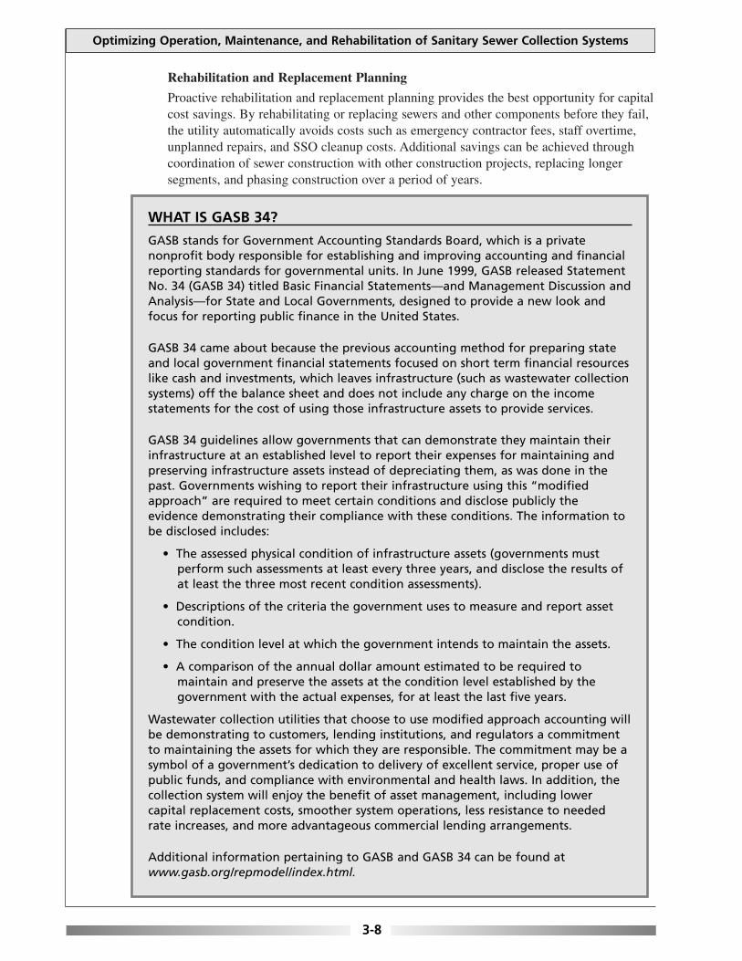
WHAT IS GASB 34?
GASB stands for Government Accounting Standards Board, which is a private nonprofit body responsible for establishing and improving accounting and financial reporting standards for governmental units. In June 1999, GASB released Statement No. 34 (GASB 34) titled Basic Financial Statements—and Management Discussion and Analysis—for State and Local Governments, designed to provide a new look and focus for reporting public finance in the United States.
GASB 34 came about because the previous accounting method for preparing state and local government financial statements focused on short term financial resources like cash and investments, which leaves infrastructure (such as wastewater collection systems) off the balance sheet and does not include any charge on the income statements for the cost of using those infrastructure assets to provide services.
GASB 34 guidelines allow governments that can demonstrate they maintain their infrastructure at an established level to report their expenses for maintaining and preserving infrastructure assets instead of depreciating them, as was done in the past. Governments wishing to report their infrastructure using this “modified approach” are required to meet certain conditions and disclose publicly the evidence demonstrating their compliance with these conditions. The information to be disclosed includes:
• The assessed physical condition of infrastructure assets (governments must perform such assessments at least every three years, and disclose the results of at least the three most recent condition assessments).
• Descriptions of the criteria the government uses to measure and report asset condition.
• The condition level at which the government intends to maintain the assets.
• A comparison of the annual dollar amount estimated to be required to maintain and preserve the assets at the condition level established by the government with the actual expenses, for at least the last five years.
Wastewater collection utilities that choose to use modified approach accounting will be demonstrating to customers, lending institutions, and regulators a commitment to maintaining the assets for which they are responsible. The commitment may be a symbol of a government’s dedication to delivery of excellent service, proper use of public funds, and compliance with environmental and health laws. In addition, the collection system will enjoy the benefit of asset management, including lower capital replacement costs, smoother system operations, less resistance to needed rate increases, and more advantageous commercial lending arrangements.
Additional information pertaining to GASB and GASB 34 can be found at www.gasb.org/repmodel/index.html.
3-8

Chapter 3: OPTIMIZING ADMINISTRATIVE AND MANAGERIAL FUNCTIONS
Capacity Assurance Planning
Capacity planning should be based on:
• Review of existing capacity constraints.
• Analysis of predicted demand for sewer service based on regional growth patterns.
• Identification of current and future capacity shortfalls.
• Identification and evaluation of alternatives for correcting the deficiencies.
Benefits of Water Conservation and Efficiency
Collection systems operating at or near capacity can benefit from a program to encourage water conservation and efficiency. Water conservation and efficiency have an effect on how much wastewater is produced, thereby having a direct impact on the performance and life of a wastewater system. A reduction in the amount of wastewater generated due to improved conservation and efficiency practices that target both the engineering and behavioral practices of the community can be extremely useful to any wastewater system. However, these conservation and efficiency programs should be tailored to the local conditions, taking into account various factors to determine the proper mix of efficiency measures and the priority of the program.
One way to reduce wastewater flows is to adopt engineering practices based on modifications in plumbing, fixtures, or water supply operating procedures on the customer’s side of the meter. Installing water-saving devices and repairing leaky pipes, faucets, and toilets could save thousands of gallons of water per person per year, and greatly reduce the amount of wastewater entering the collection system and requiring treatment.
Community-wide water conservation and efficiency programs can also include water use surveys, plumbing fixture retrofit kits, rebate or incentive programs for low-flow toilet and appliance replacement, and informational/educational programs.
Additional information on the benefits of a water conservation and efficiency program and guidance on establishing a program are available from the following sources:
Water Efficiency Fact Sheet—A Technical Overview. National Small Flows Clearinghouse. No. WWFSOM33. 1998. Available at: www.nsfc.wvu.edu
On the web: American Water Works Association—Water Efficiency Clearinghouse.
Available at: www.waterwiser.org
EPA’s Water Use Efficiency Program Available at: www.epa.gov/owm/water-efficiency/index.htm
Saving Water Partnership, a group of local utilities in Seattle and King County, Washington area that fund water conservation programs.
Available at: www.savingwater.org
3-9

Optimizing Operation, Maintenance, and Rehabilitation of Sanitary Sewer Collection Systems
Maintenance Analysis and Planning
The asset management goal is to maximize planned maintenance and minimize unplanned maintenance. Planning should be performed annually and updated throughout the year as needed to address changing conditions. Maintenance activities are either planned (i.e., inspecting all major lines in the system every 15 years, cleaning all major lines on a rotating basis every five years) or unplanned (i.e., defect repair, emergency blockage removal).
Field crews should be integrally involved with maintenance planning. As the maintenance program proceeds, field staff should be encouraged to provide feedback on which strategies are working and which are not, to allow mid-course corrections if necessary.
Financial Management
The goal of sewer system financial management is to identify how much money will be needed to meet level of service goals and maintain the system at or above the identified minimum condition, forecast when the money will be needed, and use the information to set user fees, other revenues, and debt financing.
Financial forecasting should be performed over a period of five to 10 years, and should be updated annually. The annual estimate of the cost to maintain the system is included in the utility's annual financial report, along with a full accounting of cash flows, debt financing, and financial reserve activity and capital improvements program.
The high up-front costs of capital acquisition often dominate the capital improvement planning process. It is, however, important to evaluate capital improvement alternatives relative to the blend of capital and lifecycle costs and the expected useful life of the asset. Other lifecycle costs that may affect the cost of ownership include the risk of harm to human health or the environment, or the risk of private or public property damage in the event of failure.
Continuous Improvement
Continuous improvement processes are based on periodic review of systems against performance measures to identify any shortfalls. Performance measures can be related to level of service goals, condition maintenance goals, or asset management system goals.
Alternatively, if an operational or capital improvement program is completed and the expected performance improvement is not realized, further analysis may be needed to identify the most effective next actions.
3.5 Safety
The development of a safety program is a necessity for any collection system agency. The purpose of the program is to define the principles under which the work is to be accomplished, to make employees aware of safe working procedures, and to establish and enforce specific regulations and procedures. The program should be in writing (e.g., written procedures, policies and training courses) and training should be well documented. Safety training cuts across all job descriptions and should emphasize the need to recognize and address hazardous situations.
3-10

Chapter 3: OPTIMIZING ADMINISTRATIVE AND MANAGERIAL FUNCTIONS
The safety program should explicitly state the organization’s safety policy. The safety policy statement should be prepared by the top management of the collection system agency with the close consultation of the agency’s safety officer/safety consultant, and select staff, since its purpose is to let employees know that the safety program has the full support of the agency and its management.
The safety policy should:
• Define the goals and objectives of the program.
• Identify the person’s responsibilities for each element of the program.
• Affirm management’s intent to enforce safety regulations.
• Describe the disciplinary actions that will be taken to enforce safe work practices.
Within the safety program, management has the responsibility to:
• Formulate a written safety policy.
• Provide a safe workplace.
• Set achievable safety goals.
• Provide adequate training.
• Delegate authority to ensure that the program is properly implemented.
The manager/superintendent is the key to any safety program. Implementation and enforcement of the program is the responsibility of the manager. The manager/superintendent should:
• Ensure that all employees are trained and periodically retrained in proper safe work practices and safety equipment.
• Ensure that proper safety practices are implemented and continued as long as the policy is in effect.
• Provide adequate safety equipment.
• Investigate all accidents and injuries to determine their cause.
• Institute corrective measures where unsafe conditions or work methods exist.
• Ensure that equipment, tools, and the work area are maintained to comply with established safety standards.
The collection system operators are the direct beneficiaries of a safety program. The operators share the responsibility to:
• Observe prescribed work procedures with respect to personal safety and that of their coworkers.
• Report any detected hazard to a manager immediately.
• Report all accidents, even those that cause minor injuries.
• Report near-miss accidents so that hazards can be removed or procedures changed to avoid problems in the future.
• Correctly use all protective devices and safety equipment supplied to reduce the possibility of injury.
3-11

Optimizing Operation, Maintenance, and Rehabilitation of Sanitary Sewer Collection Systems
3.6 Security
As has already been discussed, the wastewater collection system represents a sizeable investment by the community, so protecting it is a critical part of managing the system. Collection systems may be vulnerable to a wide variety of threats that can affect operations including natural disasters, operator errors, vandalism, and even terrorism. By adequately preparing, the community’s investment, public health, environment, and other assets that rely on the system will be protected.
It is important to reassess the vulnerability of the collection system on a regular basis. Preparedness is not an end point, but a goal that can be achieved only through continued efforts to assess and improve the overall security of the system.
3.6.1 Securing Information
Records, maps, and other information should be stored in a secure location when not in use. Utilities should make back-up copies of all data and sensitive documents on a regular basis. Back-up material should be stored in a secure offsite location. Decision makers need to address how sensitive documents (e.g., schematics, maps, and plans and specifications) will be distributed for construction projects or other uses, and how they will be recorded and recovered after use. Measures to safeguard documents used by bidders for new projects needs to be considered as well.
All computer access should be password protected and passwords should be changed periodically and (as needed) following employee turnover. When possible, each individual should have a unique password that they do not share with others.
Supervisory control and data acquisition (SCADA) systems are computer-monitored alarm, response, control, and data acquisition systems used by collection system operators to remotely monitor and adjust the operation of equipment in the system. SCADA systems can be vulnerable to potential intruders. The most direct approach to evaluate vulnerabilities is penetration testing, which can detect vulnerability and security breaches that could be used to attack and penetrate the entire SCADA system. Hardening is the process of making the system less vulnerable through equipment upgrades, redundancy of components, etc. If you have a SCADA system, consider operating it on a system without internet access to reduce the chance of unauthorized access.
3.6.2 Securing Facilities
Access to critical components of the collection system should be limited to authorized personnel only, and staff need to understand and abide by the access policies that are established. Warning signs can be an effective means to deter unauthorized access. Check regularly to be certain signs are present and legible.
Ideally, all facilities should have a security fence around the perimeter. The fence should be walked periodically to check for breaches and maintenance needs. All windows and doors should be locked. All gates should be locked with chains and a tamper-resistant padlock. Other barriers, such as a concrete “jersey” barrier, can be considered to guard certain critical components from accidental or intentional vehicle intrusion. Systems should ensure that all security measures comply with fire codes.
3-12

Chapter 3: OPTIMIZING ADMINISTRATIVE AND MANAGERIAL FUNCTIONS
Suppliers and personnel from co-located organizations should be denied access to codes and/or keys. Change codes frequently, if possible. Entry into buildings should be under the direct supervision of collection system personnel.
Utilities should establish a policy that an authorized person, designated by the collection system agency, must accompany all deliveries. Verify the credentials of all delivery drivers, preventing unauthorized personnel from having access to the collection system.
Utilities should keep a record of locks and associated keys, and to whom the keys have been assigned. This record will facilitate lock replacement and key management (e.g., after employee turnover or loss of keys). Vehicle and building keys should be kept in a lockbox when not in use. Have all keys stamped (engraved) “DO NOT DUPLICATE”. Electronic “swipe” card systems can be an effective way to regulate access.
Collection system vehicles should be locked when not in use or left unattended. Remove any critical information about the system before parking vehicles for the night or leaving them unattended. Vehicles usually contain tools that could be used to access critical components of the collection system. Secure and account for tools daily.
Frequent and random patrolling of the above-ground portions and critical components of the collection system by utility staff may discourage potential tampering. It may also help identify problems that may have arisen since the previous patrol. Consider asking local law enforcement agencies to assist by conducting patrols of the collection system. Advise them of your critical components and explain why they are important. Watchful neighbors can be very helpful to a security program. Make sure they know who to call in the event of an emergency or suspicious activity.
When assessing the area around your collection system’s critical components, look for objects that could be used to gain entry (e.g., large rocks, cement blocks, pieces of wood, ladders, valve keys, and other tools) and remove them if possible.
Tamper-resistant bolts or other methods may be used to secure manhole covers to rims. Lastly, protection of the collection system must be considered and included in the Emergency Response Plan.
3.6.3 Employees
Personnel should be trained and knowledgeable about security issues associated with the collection system, know what to look for, and know how to report any suspicious events or activities. Periodic meetings of authorized personnel should be held to discuss security issues.
Former or disgruntled employees have knowledge of the operation of the collection system and could have both the intent and physical capability to harm the system and its related assets. Requiring employees who will no longer be working at the collection system agency to turn in their identification, keys, and access codes will help limit these types of potential security breaches.
3-13

Optimizing Operation, Maintenance, and Rehabilitation of Sanitary Sewer Collection Systems
3.7 Emergency Response Plans
The collection system agency should have in place a comprehensive plan for dealing with both routine and catastrophic emergencies. Routine emergencies include such situations as overflowing manholes, backups into homes, line breaks, localized electrical failure, and pump station outages. Catastrophic emergencies include floods, tornados, earthquakes and other natural events; serious chemical spills; widespread electrical failure. Ideally, this plan is written, reviewed and adjusted accordingly over time.
The emergency preparedness and response procedures may be contained in the authority’s O & M manual, or may be reflected in the descriptions of equipment and unit operations. However, operators looking for information on emergency procedures can find it more easily in a stand-alone document than when it’s combined with other information in the O & M manual
The plan should utilize the most up-to-date information on the collection system. A structured analysis, also called a risk assessment or vulnerability assessment, should be made of the collection system, treatment plant, and the community. The assessment should identify areas where the collection system is vulnerable to failure and determine the effect and relative severity to collection systems operations, equipment, public safety and health of such a failure. The assessment should concentrate on such factors as topography, weather, sewer system size, and other site-specific factors, which reflect the unique characteristics of the system. Once the areas of vulnerability are known, the authority should have appropriate plans in place to ensure collection system operations continue for the duration of the emergency.
The plans must clearly identify the steps staff should take in the event of emergency situations. They should include information on when it is appropriate to initiate and cease emergency operations. The plans should be very specific as to the collection system or repair equipment involved. Instructions should be available that explain how to operate equipment or systems during an emergency event when they are not functioning as intended but are not fully inoperable.
The plan should also include specific procedures for reporting events that result in an overflow or other non-compliance event to the appropriate authorities. Plans should specifically identify emergency situations, responsibilities, actions to be taken, equipment to be used and sources thereof, and notification requirements including those involving regulatory authorities but also other local agencies such as the fire dept, ambulance, Local Emergency Planning Committee (LEPC), etc.
The plan should also contain a mechanism to keep the public/users notified of impacts to them, such as outages (including projected lengths of time), road closings, etc.
Typical components of an emergency program may include:
• General information regarding emergencies, such as telephone numbers of collection system personnel, fire department, and ambulance.
• Identification of hazards (e.g., chlorine storage areas) and use of universal classification system for hazards: Combustible material, flammable liquids, energized electrical circuits, and hazardous materials.
3-14

Chapter 3: OPTIMIZING ADMINISTRATIVE AND MANAGERIAL FUNCTIONS
• Vulnerability analysis in which the collection system identifies the various types of emergencies that could occur, such as natural or man-made disasters, power outages, equipment failures, vandalism, or other intentional acts of disruption.
• Emergency response procedures.
• Methods to reduce risk of emergencies.
• Responsibilities of staff and management.
An emergency response plan should provide a framework describing how the collection system agency would notify the public, as well as other entities, of sanitary sewer overflows that may imminently and substantially endanger human health as well as cause inconveniences. The emergency response plans provision should not dictate the specific procedures or the specific information that would be provided through immediate notification. Rather, the emergency response plan, in consultation with potentially affected entities, should establish a framework for case-by-case notification, which depends on the nature of the overflow event and the responsibilities of different local entities.
Given the complexities of immediate notification, it is critical to use the flexibility of a system-specific overflow emergency response plan to identify and clarify specific notification responsibilities and notification protocols. The emergency response plan should identify appropriate authorities at the local, county, and/or State level to receive notification and identify the roles and relationships of the collection system agency, public health authorities, and other authorities, including lines of communication and the identities of responsible officials.
A representative from management should be given the role of dealing with the media to address public concerns. All other employees should refer inquiries to this designated spokesperson when contacted by the media.
Collection system operators must be prepared to respond to routine emergencies with resources that include appropriate procedures, spare parts, repair materials and equipment. Extraordinary emergencies caused by natural events or manmade events tend to affect wider areas and other utilities. These emergencies require greater time and resources due to the complexity of coordinating an effective response. Therefore, it is essential to have in place an effective emergency management plan to reduce the impact of extraordinary and routine emergencies.
Procedures for the emergency response plans should be understood and practiced by all personnel in order to ensure safety of the public, and the collection system personnel responding. Procedures need to be specific to the type of emergency that could occur. It is important to keep detailed records of all past emergencies in order to constantly improve response training, and the method and timing of future responses.
The ability to deal with emergencies depends on the knowledge and skill of the responding crews, in addition to availability of equipment. The crew needs to be able to rapidly diagnose problems in the field under stress, but they must also select the right equipment needed to correct the problem. Crews therefore need immediate access to appropriate tools and equipment if emergencies are to be dealt with as rapidly as possible. If resources are limited, consideration should be given to contacting other departments or contracting with private industries to respond to some emergency situations, for example, those emergencies that would occur after normal hours of operation.
3-15
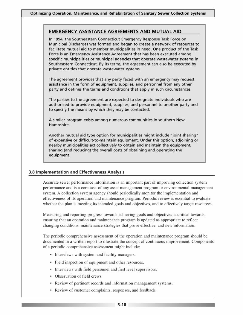
Optimizing Operation, Maintenance, and Rehabilitation of Sanitary Sewer Collection Systems
EMERGENCY ASSISTANCE AGREEMENTS AND MUTUAL AID
In 1994, the Southeastern Connecticut Emergency Response Task Force on Municipal Discharges was formed and began to create a network of resources to facilitate mutual aid to member municipalities in need. One product of the Task Force is an Emergency Assistance Agreement that has been executed among specific municipalities or municipal agencies that operate wastewater systems in Southeastern Connecticut. By its terms, the agreement can also be executed by private entities that operate wastewater systems.
The agreement provides that any party faced with an emergency may request assistance in the form of equipment, supplies, and personnel from any other party and defines the terms and conditions that apply in such circumstances.
The parties to the agreement are expected to designate individuals who are authorized to provide equipment, supplies, and personnel to another party and to specify the means by which they may be contacted.
A similar program exists among numerous communities in southern New Hampshire.
Another mutual aid type option for municipalities might include “joint sharing” of expensive or difficult-to-maintain equipment. Under this option, adjoining or nearby municipalities act collectively to obtain and maintain the equipment, sharing (and reducing) the overall costs of obtaining and operating the equipment.
3.8 Implementation and Effectiveness Analysis
Accurate sewer performance information is an important part of improving collection system performance and is a core task of any asset management program or environmental management system. A collection system agency should periodically monitor the implementation and effectiveness of its operation and maintenance program. Periodic review is essential to evaluate whether the plan is meeting its intended goals and objectives, and to effectively target resources.
Measuring and reporting progress towards achieving goals and objectives is critical towards ensuring that an operation and maintenance program is updated as appropriate to reflect changing conditions, maintenance strategies that prove effective, and new information.
The periodic comprehensive assessment of the operation and maintenance program should be documented in a written report to illustrate the concept of continuous improvement. Components of a periodic comprehensive assessment might include:
• Interviews with system and facility managers.
• Field inspection of equipment and other resources.
• Interviews with field personnel and first level supervisors.
• Observation of field crews.
• Review of pertinent records and information management systems.
• Review of customer complaints, responses, and feedback.
3-16

Chapter 3: OPTIMIZING ADMINISTRATIVE AND MANAGERIAL FUNCTIONS
3.9 More Information
The American Public Works Association (APWA) has developed a guidance document for preparing sewer overflow response plans titled Preparing Sewer Overflow Response Plans—A Guidebook for Local Governments, which is available (for a fee) from APWA. The APWA website is www.apwa.net and their telephone number is 1-816-472-6100.
CHAPTER 3 REFERENCES
Collection Systems: Method for Evaluating and Improving Performance. California State University, Sacramento. 1998. Guide for Evaluating Capacity, Management, Operation, and Maintenance Programs for Sanitary Sewer Collection Systems
(DRAFT). U. S. Environmental Protection Agency. 2000. EPA No. 300-B-00-014. Utility Management. California State University, Sacramento. 1998. Operation and Maintenance of Wastewater Collection Systems (Volume I)- Fifth Edition California State University,
Sacramento. 1998. Operation and Maintenance of Wastewater Collection Systems (Volume II)- Fifth Edition California State University,
Sacramento. 1998. Asset Management for Sewer Collection Systems—Fact Sheet. U. S. Environmental Protection Agency. 2002.
Available at: www.epa.gov/npdes/pubs/assetmanagement.pdf Draft Notice of Proposed Rulemaking—NPDES Permit Requirements for Municipal Sanitary Sewer Collection Systems,
Municipal Satellite Collection Systems, and Sanitary Sewer Overflows. U. S. Environmental Protection Agency. January 4, 2001.
Protecting Your Communities Assets: A Guide for Small Wastewater Systems. National Environmental Training Center. November 2002. Available at: www.nesc.wvu.edu/netcsc/
Asset Based Vulnerability Checklist for Wastewater Utilities. Association of Metropolitan Sewerage Agencies. 2002. Available at: www.amsa-cleanwater.org/pubs/2002avcheck.pdf
3-17

This page is intentionally blank.

Optimizing Operation, Maintenance, and Rehabilitation of Sanitary Sewer Collection Systems
CHAPTER 4
OPTIMIZING LEGAL AUTHORITY
Many municipalities have developed sewer use ordinances that improve performance and ensure proper maintenance of their wastewater collection system. The sewer use ordinance is a legal document that authorizes how the utility manages, operates and maintains its wastewater collection system. Establishing or strengthening sewer use ordinances is a means of improving collection system performance.
Information for this chapter was primarily obtained from the following sources: Parsons, Inc.’s Municipal Ordinance Considerations and Suggested Language to Help Control Sewer System Overflows (DRAFT), and the Water Environment Federation’s Control of Fats, Oil, and Grease (FOG)—Advanced Training Course.
4.1 Sewer Use Ordinances
Despite unique community conditions, the following is a list of general performance-affecting issues that most collection system agencies face. These include:
• The need to control infiltration, inflow, and exfiltration.
• The need to ensure proper design, installation, and inspection of sewer lines.
• The need to maintain all sewer line components, including those owned by private and public entities.
• The need to reduce the disposal of substances into the sewer line that can cause performance problems.
• The need to find and eliminate illegal connections (sump pumps, roof leaders, foundation drains, etc.).
Recognizing the health and legal problems that can result from sanitary sewer overflows and backups, an increasing number of municipalities have enhanced their community’s sewer use ordinance to address the collection system issues identified above.
A sewer use ordinance is a statute that is enacted by the legislative body of the municipal corporation for public purposes in that jurisdiction. Municipalities adopt ordinances for public or government purposes to facilitate the general administration and public welfare of the local community, within delegated authority provided by the State constitution or State statutes.
A statute must be enacted by being formally introduced, voted upon favorably, and adopted by the municipal legislative body (usually referred to as the city council, town council, village council, board of alderman, board of selectmen), and then signed into law by the municipal executive authority (e.g., mayor, city manager, commissioner, supervisor).
To be valid, a sewer use ordinance cannot conflict with the State’s constitution, general statutes, or the charter or other special legislative acts under which the municipal corporation operates.
4-1

Optimizing Operation, Maintenance, and Rehabilitation of Sanitary Sewer Collection Systems
The ordinance may impose more vigorous or definite requirements, in addition to those imposed by the State legislature, provided that those requirements are consistent with and do not conflict with the governing State statute.
If there is an existing sewer use ordinance, it should be reviewed periodically to determine whether the ordinance’s contents still meet the collection system’s need (including issues such as enforceability). Where there is not an ordinance in place, one should be developed. System managers may wish to consider current and reasonably anticipated future challenges confronting their systems and how various changes to the ordinance might help meet challenges.
It is frequently useful to consult with legal/legislative counsel for the municipal corporation and/or a potential legislative sponsor to gain insights on the most effective form and contents for the prospective changes or new sewer use ordinance.
4.1.1 Suggested Language
The following information provides potential sewer use ordinance language options that may be appropriate to include in a municipal ordinance or amendment. The information presented contains examples of actual sewer use ordinances enacted to address specific collection system issues. They are not presented with the intention that all elements should be universally adopted. Since local conditions vary, consulting with local legal and legislative authorities to determine which ordinance language options, and exact statutory language, best meet the local need is advised.
Inflow Control
No person shall discharge or cause to be discharged, either by gravity drain or by force pump, any storm water, surface water, groundwater, roof runoff, subsurface drainage, cooling water, or unpolluted . . . process waters to any sanitary sewer. No person shall at any time make any connection of any source of storm runoff, ground water, or sources of uncontaminated water directly, or indirectly, to a sewer extension, existing public or private sewer, interceptor sewer. (Manhattan, Kan., Code of Ordinances ch. 32, art. III, div. 4, § 32-159 (1974))
Infiltration Control
The allowable infiltration for all existing sanitary sewers is hereby established at no more than two hundred (200) gallons/inch sewer diameter/day/mile for sewers twenty-four (24) inches in diameter and smaller. All new sewers shall be designed and constructed in accordance with State regulations and tested for infiltration in accordance with an acceptable testing method of the State Department of Public Health. (Edmond, Okla., Code of Ordinances tit. 13, ch. 13.16, 13.16.070 (1980))
Responsibility for Inspections of Existing Lines
Any person owning or occupying a tract or parcel of land upon which sanitary sewer service lines are located which flow into public lines in city streets, alleys and easements (including, but not limited to, single-family or duplex residences, mobile homes and/or trailer parks, apartments, places of business, schools, hospitals, churches, structures of any kind, vacant buildings, or vacant land) shall be responsible for the inspection, maintenance, repair and operational integrity of such private sanitary sewer service line. (Friendswood, Tex., Code of Ordinances pt. II, ch. 78, art. III, div.3, subdiv. II, § 78147.(a) (1992))
4-2

Chapter 4: OPTIMIZING LEGAL AUTHORITY
Time of Transfer Inspection Programs
Prior to the original connection, reconnection or transfer of water and/or sewer service to a tenant or property owner, the city may inspect or require the inspection of private sanitary sewer service lines thereon for the purpose of determining the amount of infiltration and inflow into such lines, if any. Inspections shall be made or required when, based upon local infiltration and inflow conditions and experience, the director of public works has determined that such inspections are necessary to effectuate the purposes of this subdivision. Any conditions discovered in such line inspections causing or allowing infiltration or inflow shall be repaired by the property owner or tenant, or agent thereof, prior to such original connection, reconnection or transfer of city water and/or sewer service, as applicable. Where conditions have been discovered on existing private service lines but for which no application for reconnection or transfer to city service has been sought, the property owner or tenant shall cause such repairs and maintenance to be performed in accordance with sections 78-150 and 78-151. (Friendswood, Tex., Code of Ordinances pt. II, ch. 78, art. III, div. 3, subdiv. II, § 78-148 (1992))
[Note: Time of transfer inspection programs are also effective for eliminating illicit connections to the municipal stormwater collection system and identifying sources of private infiltration.]
Inspection Programs – Power and Authority of Inspectors
The City shall be permitted to enter all properties for the purposes of inspection, observation, measurement, sampling and testing in accordance with the provisions of this chapter. (Edmond, Okla., Code of Ordinances tit. 13, ch. 13.16, 13.16.090 (1980))
Main, Trunk and Lateral Extensions – Permit Required to Connect with Sewers
Any project which is of sufficient discharge capacity and requires a state sewer extension permit pursuant to Massachusetts Sewer System Extension and Connection Permit Program . . . must contribute to the reduction of infiltration and inflow to the public sewer system. This may be in the form of a limited inflow/infiltration study, actual removal of inflow/infiltration by pipeline rehabilitation, combined sewer separation, storm drain installation, specific pipeline maintenance projects, a permit fee or other method as approved by the sewer commission and department of public works.
Such inflow/infiltration reduction must establish an effective removal or planned removal of five times that volume proposed to that which is being introduced [by the sewer line extension]. (Fall River, Mass., Revised Ordinances pt. II, ch. 74, art. III, div. 2, § 74-202 (1988))
Private Line Specifications/Standards for Sewer Connections
The building sewer shall be connected into the public sewer at the property line by the City, subject to fee outlined in section . . . of this article. Direct stub-ins through the wall of the sewer pipe shall not be permitted. Whenever possible, the connection shall be made at the top of the pipe and smooth bends not exceeding forty-five (45) degrees shall be used in the service pipe to prevent clogging. A neat workmanlike connection shall be made. (Alexandria, La., Code of Ordinances pt. II, ch. 27.5, art. I, § 27.5-4(l) (1980))
Inspection and Testing of New Sewers
4.2. Testing. The developer or contractor under the supervision of the city engineer will test all sewers constructed for city acceptance as follows:
4-3

Optimizing Operation, Maintenance, and Rehabilitation of Sanitary Sewer Collection Systems
4.2.1. Infiltration-exfiltration test.
Where the groundwater table is more than four feet above the average invert of the sewer being tested, or less than four feet below the average ground surface, an infiltration test will be conducted. Where the groundwater table is not within the limits above, an exfiltration test will be conducted.
4.2.2. Television inspection.
In addition to the infiltration and exfiltration testing, the sewer will be examined by the city’s sewer television truck. Any significant defects of any nature observed by the television technician will be required to be repaired and reinspected. Breaks, separations, improper lateral connections, and deviation from proper grade resulting in standing water are examples of defects found by this method. (Slidell, La., Code of Ordinances app. B, div. II, sec. 5, 4.2 (2000))
Private Line Specifications/Standards for Sewer Connections
The applicant for the building sewer permit shall notify the plumbing inspector when the building sewer is ready for inspection and connection to the public sewer. The connection shall be made by the city wastewater department. The connection of the building sewer into the public sewer shall conform to the requirements of the building and plumbing code or other applicable rules and regulations of the city, or procedures set forth in appropriate specifications of the ASTM and the WPCF Manual of Practice No. 9. All such connections shall be made gastight and watertight. The plumbing inspector before installation must approve any deviation from the prescribed procedures and materials. (Alexandria, La., Code of Ordinances pt. II, ch. 27.5, art. I, § 27.5-4(m) (1980))
Connection to Public Sewers Required
The owner(s) of all houses, buildings, or properties used for human occupancy, employment, recreation, or other purposes, situated within the (-CVT), and abutting any street, alley, or right-of-way in which there is now located or may, in the future, be located a public sewer, is hereby required, at the owner’s expense to install suitable sanitary facilities therein, and to connect such facilities directly with the proper public sewer, in accordance with the provisions of this law, within ninety (90) days after official notice to do so, provided that said public sewer is within one hundred feet (30.5 meters) of the property line. (New York State Department of Environmental Conservation—Model Sewer Use Law. 1994 Revision)
4.1.2 Design Standards
Quality sanitary sewer designs keep costs and problems associated with construction, operations, and maintenance to a minimum. Design flaws are difficult to correct once construction is complete. For this reason design standards should be incorporated into the community sewer use ordinance. Ideally, the sewer use ordinance should contain standards for new construction, procedures for reviewing designs and protocols for inspection, start up, testing and approval of new construction. The procedures should provide for documentation of all activities, especially inspection.
4-4

Chapter 4: OPTIMIZING LEGAL AUTHORITY
4.2 Fats, Oil, and Grease Control
Fats, oil, and grease (FOG), primarily generated from restaurants and other institutional food service establishments, are major contributors to collection system blockages and overflows. Institutional food service establishments include, but are not limited to: mall food courts, food manufacturers, food packagers, restaurants, grocery stores, bakeries, lounges, hospitals, hotels, nursing homes, churches, and schools. Apartment and condominium complexes can also be major sources of FOG.
The effective management of FOG in sanitary sewer collection systems requires a strong legal foundation. This foundation is often manifested in a municipality’s sewer use ordinance or a separate FOG management ordinance. The management ordinance should be a complete outline of the FOG management program. The program’s legal ordinance should refer to all of the basic requirements of the program and leave the details of the implementation to rules and regulations that can be developed and changed, as needed. One common practice is to develop a FOG Best Management Practices Manual and incorporate the manual by reference into the ordinance.
An effective grease control ordinance should establish the authority to:
• Establish who is regulated under the ordinance.
• Require grease interceptors, which are more effective than grease traps.
• Establish interceptor and/or trap design, construction, and inspection standards.
• Establish management, operation, and maintenance standards.
• Establish record keeping and reporting requirements.
• Regulate additives and alternative grease control devices.
• Issue individual/tailored permits or set a performance standard.
• Regulate grease haulers and establish fees.
• Regulate the proper disposal of FOG removed from grease traps and interceptors.
Establishing a local FOG management program is a resource-intensive undertaking. The resource requirements must be carefully considered when establishing a new program and municipal management authorities should be made aware of the required resource commitment early in the planning stages.
4.3 Private/Satellite Systems
A large number of public and private entities may own different pipes and other components of the entire municipal sanitary sewer collection system. In some situations, the municipality that owns the collector sewers may not provide treatment of wastewater, but only convey its wastewater to a collection system that is owned and operated by a different municipal entity. In addition, private satellite collection systems are associated with a wide range of entities such as trailer parks, residential subdivisions, apartment complexes, commercial complexes such as shopping centers, industrial parks, college campuses, military facilities, hospitals, and prisons.
The collection system authority should have a comprehensive program, which addresses flows from satellite communities. Satellite communities must not be allowed to contribute excessive flows that cause or may contribute to overflows, flooding or non-compliance at the wastewater
4-5

Optimizing Operation, Maintenance, and Rehabilitation of Sanitary Sewer Collection Systems
treatment plant. Should any of these situations exist, it is not sufficient that the authority merely charges the satellite community for the excess flow. The authority must be able to prohibit the contribution of the excess flow.
4.4 Private Inflow Control
Inflow is a system-wide problem, which, if not addressed, can result in SSOs and backups into buildings with significant adverse impacts to public health, welfare and the environment. Local projects to identify and remove inflow sources from private property (Private Inflow) are hindered on several fronts.
It is often difficult to convince local elected officials that the public health and environmental benefits of private inflow removal outweigh the potential local public outcry often associated with inspection/enforcement on private property. Also, local Sewer Use Ordinances often lack effective and employable measures for such enforcement.
There must be recognition that private inflow control is a complex issue and undertaking which requires a concerted and cooperative effort by a number of stakeholders, including homeowners, municipal officials and local agencies (including public works, building permits, plumbing inspector and board of health) and the State water pollution control agency.
Each wastewater system owner/operator should establish a Comprehensive Inflow Removal Program (Program). The Program should include a specific schedule for finding and redirecting all such sources unless the property owner can provide written documentation that the removal of the inflow source(s) will result in a severe financial burden. The Program should include procedures for periodic post-removal re-inspection to ensure that the inflow source(s) are not reconnected.
The wastewater system owner/operator should consider the following elements when designing its Program:
• Assess total system-wide costs to correct the problem and how corrective costs should be allocated.
• Inclusion of a one-time amnesty provision to get voluntary compliance.
• Consider financial assistance for building owners, such as providing homeowners with free technical assistance to design a fix, and an interest free loan to implement improvement.
• Assess local storm drainage system and its ability to provide a specific drain-connection to the property line to allow homeowners to disconnect/reconnect private inflow sources.
• Coordinate private source implementation work with other municipal utility and/or roadway reconstruction activities (e.g., integrate work into larger construction projects to minimize costs and inconvenience).
• Coordinate activities with building and plumbing permit and inspection programs.
Any program for removal of private inflow must specifically include a process for direct technical assistance to the property owner so that a viable and cost-effective alternative to continued connection to the wastewater system could be determined and implemented. It will be
4-6

Chapter 4: OPTIMIZING LEGAL AUTHORITY
difficult to implement a successful private inflow control program without the inclusion of such technical assistance; the property owner needs to see that a feasible cost-effective option actually exists.
The program must include outreach and education components to alert homeowners to the fact that their private inflow source(s) is contributing to problems in the wastewater system that could be causing specific local system overflows into nearby water bodies and/or backups into buildings, which could increase costs for all rate payers due to additional fees now and in the future.
WHAT ABOUT ILLICIT CONNECTIONS TO THE STORMWATER SYSTEM?
Municipal separate stormwater collection/conveyance systems frequently have illegal wastewater connections (e.g. illicit connections), or other contaminated discharges, which can pose significant threats to public health, welfare and the environment and severely restrict the beneficial uses of local waterways. Even a relatively small number of illicit connections can result in extensive degradation to the receiving water where the contaminated stormwater discharges.
Finding and eliminating illicit connections requires a series of concurrent and sequential actions that need to be carefully coordinated. Basic initial elements include:
• Preparation of maps showing the locations and size of each stormwater discharge pipe, and if possible, the tributary drainage area.
• Visual observation of each of the stormwater discharge pipes to determine whether the discharge is active during dry weather.
• Sampling of each of the active dry weather discharges from stormwater outfalls to determine whether the discharge contains pollutants that would indicate illicit connections to the system.
• Development of a plan to identify and eliminate illegal sewer connections to the storm drains for areas where sampling results indicate the presence of sanitary sewer flows.
• Update, as necessary, local sewer use ordinance and drain connection regulations relative to preventing and eliminating illicit connections and/or cross connections (e.g. common manholes) between separate sewerage and stormwater systems.
Even though a successful illicit connection program can remove significant sources of contamination, it comes with a cost, both political and financial. Since most illicit connections are from private buildings, the program will require the direct involvement of the public and will include such unpopular actions as access onto/into private property and often enforcement against individual building owners. The financial impacts can also be significant.
A major goal of an illicit connection program must be to develop a cost effective, systematic and expeditious approach for identifying illegal connections. Historically, illegal connection investigations are performed by visually inspecting manholes starting at the lower reaches of the drainage area, near the outfall. Once a source of sanitary influence is identified, further
continued on page 4-8
4-7

Optimizing Operation, Maintenance, and Rehabilitation of Sanitary Sewer Collection Systems
investigation of the drainage area would be suspended until the correction was made. After correction, follow-up inspections are performed. However, in many cases, there is still evidence of an upstream source of sanitary sewage and additional investigation is required.
A methodology recently developed by the Boston Water and Sewer Commission begins by defining smaller sub-areas. Visual inspections of storm drain manholes are performed starting at the upper reaches of the drainage area and working downstream. The inspections are performed only after 48 hours of dry weather. If flow is observed in a manhole, the flow is tested in the field for ammonia and surfactants using a field test kit. If no flow is observed, manholes at key junctions of the sub-drainage area are sandbagged for 48 hours to capture possible intermittent flow from upstream storm drains. Any flow that is captured is inspected for evidence of contamination. If evidence of contamination exists, upstream buildings are dye tested to determine the source of the contamination. Manhole inspections downstream of the suspected source of contamination are suspended until all upstream sources are identified and corrected. This way one can be almost assured that no illegal connections are missed.
Additional information on illicit connections is available in a NEIWPCC guidance document titled Illicit Discharge Detection and Elimination Manual—A Guidebook for Municipalities, which can be downloaded at: www.neiwpcc.org.
WHAT ABOUT ILLICIT CONNECTIONS TO THE STORMWATER SYSTEM? continued from page 4-7
4.5 More Information
The New York State Department of Environmental Conservation has a web page containing information about sewer use and water efficiency, as well as fats, oil, and grease control. The web page is available at: www.dec.state.ny.us/website/dow/bwcp/seweruse_mp.html.
The New York State Department of Environmental Conservation has developed a Model Sewer Use Law that is intended to aid municipalities in developing or modifying their sewer use laws. The Model Sewer Use law is available at: www.dec.state.ny.us/website/dow/bwcp/seweruselaw.htm.
Additional information on successful fats, oil, and grease control programs is available from the following organizations.
• North Carolina Department of Environment and Natural Resources, Division of Pollution Prevention and Environmental Assistance. Oil and Grease Documents available at: www.p2pays.org/food/main/oil.htm.
• Georgia Department of Natural Resources, Pollution Prevention Assistance Division. Fats, Oils, and Grease Initiative Documents available at: www.dnr.state.ga.us/p2ad/h_fog_initiative.html.
• Oregon Association of Clean Water Agencies. Fats, Oil, and Grease Best Management Practices Manual available at: www.oracwa.org/.
4-8

Chapter 4: OPTIMIZING LEGAL AUTHORITY
CHAPTER 4 REFERENCES
Municipal Ordinance Considerations and Suggested Language to Help Control Sewer System Overflows (DRAFT). Parsons, Inc. 2002. EPA Contract No. 68-C-00-116, Work Assignment No. 1-03.
Control of Fats, Oil, and Grease (FOG)—Advanced Training Course. Water Environment Federation. July 2002.
Draft Notice of Proposed Rulemaking—NPDES Permit Requirements for Municipal Sanitary Sewer Collection Systems, Municipal Satellite Collection Systems, and Sanitary Sewer Overflows. U. S. Environmental Protection Agency. January 4, 2001.
Guide for Evaluating Capacity, Management, Operation, and Maintenance Programs for Sanitary Sewer Collection Systems (DRAFT). U. S. Environmental Protection Agency. 2000. EPA No. 300-B-00-014.
Model Sewer Use Law—Incorporating Federal Pretreatment Language. New York State Department of Environmental Conservation. 1994 Revision.
4-9

This page is intentionally blank.

Optimizing Operation, Maintenance, and Rehabilitation of Sanitary Sewer Collection Systems
CHAPTER 5
EFFECTIVE COMMUNICATION
Collection system owners and operators must communicate effectively with municipal authorities, state and federal regulators, and the general public. Enhancing communication is an integral part of optimizing an operation and maintenance program.
Information for this chapter was primarily obtained from the following sources: U.S. EPA’s Guide for Evaluating Capacity, Management, Operation, and Maintenance Programs for Sanitary Sewer Collection Systems (DRAFT) and Draft Notice of Proposed Rulemaking—NPDES Permit Requirements for Municipal Sanitary Sewer Collection Systems, Municipal Satellite Collection Systems, and Sanitary Sewer Overflows; U.S. DHHS’s Communicating in a Crisis: Risk Communication Guidelines for Public Officials; and the Maine Department of Environmental Protection’s O&M Newsletter.
5.1 Working with the Public
Improving public awareness is important because the public can play a key role in improving collection system performance. The public is a key stakeholder that should have an opportunity to identify its concerns and expectations regarding the performance of collection systems and potential public health and environmental risks.
The public does not always understand the benefits to be derived from collection system projects that may significantly raise their user rates and require temporary or permanent disruption. Public officials in turn may not be willing to counter public sentiment. Therefore, it is important to engage and inform stakeholders early and maintain communication throughout the project process.
Education is a vital tool that can eliminate potential barriers or opposition related to funding and siting, provide support for the project, and reduce overall costs and disruptions. The public is usually more willing to pay for improvements it can see and understand.
The ability to establish constructive communication will be determined, in large part, by whether an audience perceives you to be trustworthy and believable. Consider how they form their judgments and perceptions. Key factors in assessing trust and credibility are: empathy and caring; competence and expertise; honesty and openness; and dedication and commitment.
5.1.1 Outreach
As stated earlier, building public support can be challenging. Holding an “Open House” can be an effective tool for building support, especially for larger system improvement projects requiring public “buy-in.” The difference between an Open House and a public meeting is that a public meeting allows a project to be formally presented to all attendees at once, while an Open House allows for more one-on-one interaction. An Open House may include relevant displays and handouts, but not formal presentations.
5-1

Optimizing Operation, Maintenance, and Rehabilitation of Sanitary Sewer Collection Systems
FIVE RULES FOR BUILDING TRUST AND CREDIBILITY
1. Accept and involve the public as a partner. Work with and for the public to inform, dispel misinformation and, to every degree possible, allay fears and concerns.
2. Appreciate the public’s specific concerns. Statistics and probabilities don’t necessarily answer all questions. Be sensitive to people’s concerns and worries on a human level. Do not overstate or dwell on negatives, but do empathize with the public and provide answers that respect their humanity.
3. Be honest and open. Once lost, trust and credibility are almost impossible to regain. Never mislead the public by lying or failing to provide information that is important to their understanding of issues.
4. Work with other credible sources. Conflicts and disagreements among organizations and credible spokespersons create confusion and breed distrust. Coordinate your information and communications efforts with those of other legitimate parties.
5. Meet the needs of the media. Never refuse to work with the media. The media’s role is to inform the public, which will be done with or without your assistance. Work with the media to ensure that the information they are providing the public is as accurate and enlightening as possible. Designate a media coordinator and have other employees refer media questions to this person.
In addition to public meetings and open houses, there are a number of options available for presenting information to the public. These include direct mail, an insert into a water/sewer bill, publishing a notice in a local newspaper, or an addendum to other existing printed materials or notices such as signs or public health advisories posted at recreation areas. The internet is likely to be an increasingly desirable medium for making information available to the public. One option is to make the information available on the municipality’s website.
Citizen advisory committees also work very well for community outreach. These committees include members of the community who volunteer to be a liaison between the municipality, consulting engineers, and the public. The committee mechanism assures the public that their concerns are being addressed. This provides “buy-in” to the process and the results.
5.1.2 Signage
An important form of outreach and communication involves the posting of chronic overflow locations. Long-term posting might be appropriate in locations where releases from the collection system are likely to re-occur, including emergency overflow structures, pump stations experiencing releases, and locations where remediation and rehabilitation require capital planning and construction over a long period of time.
5-2

Chapter 5: EFFECTIVE COMMUNICATION
Posting is also appropriate at locations where public exposure is more likely, such as swimming areas or parks. Posting at selected public places (e.g., a public information center at a park, beach, or school) might be appropriate in cases where a relatively narrow segment of the public is likely to be affected and can be reached via the public places selected for display.
Posting locations should be identified in consultation with other affected entities, such as local, State, or tribal public health officials; and parks and recreation officials. This consultation would occur as part of an integrated public outreach process.
Information provided in posted areas should include information such as the following:
• When exposure at this location could pose risks (e.g., “during and immediately after heavy rains”).
• Where exposure may be a problem (e.g., “within 500 feet of this sign”).
• The nature of the problem (e.g., “this sewer may overflow and discharge raw sewage”).
• Why exposure should be avoided (“bacteria may cause illness”).
• How to avoid exposure (“do not swim or wade in this area”).
• Where to get more information.
• Request for public assistance in reporting discharges (“if you see a discharge from this pipe, please call [specified phone number]”).
The information would need to be targeted to the potentially affected population, including consideration for non-English-speaking individuals.
5.1.3 Alternative Dispute Resolution
Collection systems agencies and the communities they serve often have to deal with complicated projects and environmental decisions, which can hinge on difficult economic, environmental, and quality of life trade-offs. Debates about these issues can become divisive and lead to conflict, deadlock, or long and expensive legal proceedings. Alternative dispute resolution is used to describe a range of techniques that can help people settle their disputes without having to resort to litigation or to reach settlement more efficiently within existing litigation proceedings. It is based on the concept that people who are involved in a controversy are the ones best able to develop a reasonable and enduring solution because they know their own needs and interests.
Most alternative dispute resolution techniques involve the use of a neutral third party, who helps orchestrate the process and ensures that it is implemented fairly and that everyone is heard and shares in the decision making process.
Constructive engagement, conflict assessment, facilitation, mediation, and consensus building are all alternative dispute resolution techniques. These techniques offer the opportunity to improve communication among stakeholders and can promote better relations among groups that have been at odds. These techniques can save all stakeholders time, money, and stress in the long run if used appropriately and conducted efficiently.
5-3
Optimizing Operation, Maintenance, and Rehabilitation of Sanitary Sewer Collection Systems
5.2 Working with Local Government
Often, resistance by chief financial officers and other upper management executives can be a critical barrier to implementing collection system improvement projects. The following outline illustrates the kind of information that needs to be presented to successfully gain approval for such a project.
The information below is useful for effectively presenting a project to an authorizing or approval authority at an oversight board or local government meeting. In deciding who should be invited to the meeting, consideration should be given to impact on budgets as well as on operations. It is most important that all interested parties be fully informed before the meeting, so they can be prepared to participate. If your project gets approved, funding may have to come from other activities; those managers must be fully involved before your presentations, if you are to avoid having them oppose your project.
Besides gaining the cooperation of internal management, it might be wise to gain the support of outside parties, who might lend additional credibility to your proposal.
Your presentation to management must be tailored to the scope of the project and the management style of your leadership, and must be keyed to achieving a decision. The best idea is to make the individual in your management scheme that can ultimately approve the project the center of your presentation.
Your presentation should present all of the necessary information as concisely as possible. Do not waste valuable time with unimportant details. The more irrelevant details you furnish, the greater the likelihood that someone will start to nit-pick. This may well divert the decisionmaker’s attention from the true issues at hand.
5.2.1 Effective Project Presentation
The following outline suggests a format for presenting your project to management.
State the purpose of the presentation.
You want everyone attending your presentation to focus on the problem you will present, knowing that a decision will have to be made. If attendees think they are there for an information briefing, they may easily miss some of the points that will critically affect the decision.
State the problem to be corrected.
What are the existing conditions that make it important that the project be considered? What costs are involved that can be reduced? How do existing conditions affect production, staffing, maintenance, and the bottom line?
Describe the scope of the project being proposed.
As briefly as possible and using a minimum of detail describe what the project will consist of in terms of equipment, labor, time and cost to implement. This part of the presentation will help the decision-maker and other key players get a fast understanding of what you want to accomplish and how.
5-4

Chapter 5: EFFECTIVE COMMUNICATION
State the benefits to be achieved by implementing the project.
Using simple data summaries and graphical displays, explain how the project will cure the problems you earlier laid out in discussing existing conditions and improvements to the bottom line. Emphasize reducing costs.
Clearly state the cost of the implementation.
Accurately state what it will cost to perform the project. You must examine all of the direct costs involved, and also the indirect costs, as well as a percentage (e.g., 10 percent) for contingencies. Will there be additional costs?
Explain any effect the project will have on operations.
While this project is going on, will there be any adverse effect on operations? If so, how will it be accommodated? Has the resultant cost of any such impact been included in the estimate of the cost of the implementation?
Present the effect on the budget.
Any significant new project will affect the budgeting process. If the project is being sought for the current budget year, the effect is likely to be both large and widespread, having an effect on more than just one part of the organization. If the project is for a future budget year, the planning may be simplified, but the effect may be felt throughout the organization. Unless a windfall of new revenue exists to fund the project, funding will have to come from existing budget items that will have to be reduced. Advance coordination with the likely targets of these budget transfers can help in getting approval. It may be necessary to clearly demonstrate a long-term benefit to be derived to convince a senior manager that he or she can accept a short-term loss of funds to support the project.
Much care should go into analyzing the Return on Investment (ROI), that is, the time over which the savings to be realized by the project equals the cost of implementing it. The shorter the ROI, the more likely the project will be approved. This part of the presentation may be a good time to compare graphically costs against time and present the expected returns to clearly illustrate the ROI. It is also a good time to restate any reduction in cost per unit of production to be realized under the project.
A major barrier to project approval is often a lack of management awareness of real operational costs. Collection/estimation of these costs, and simple graphical displays in your presentation can help highlight the need for the project.
Provide a coordinated implementation plan.
The best plan, implemented poorly, can be a total failure. Coordination between and among departments; realistic work schedules; accommodation for the unexpected; clearly stated, achievable milestones; and the assignment of a fully accountable project manager are essential to making the project a success. “What if” brainstorming should always be included in the planning. Under best conditions all of the affected activities should be in agreement on the plan before the decision briefing is presented. If such agreement is not possible in advance, the plan should include an early milestone related to achieving that level of agreed-to coordination. The timing for the project and each of the milestones are critical to the decision process. The latest date a decision can be useful must be made clear. Normally, this time estimate should allow management some time to consider
5-5

Optimizing Operation, Maintenance, and Rehabilitation of Sanitary Sewer Collection Systems
options and alternatives. However, it must be made clear that the reason the project is being sought is because a decision is needed, and it is needed by a specific date.
Summarize the project and ask for the decision.
Close the sale. Summarize the need for the project and timing, review the cost/benefit analysis, lead the thought process to conclude the need for a decision, and ask that the decision be made.
Provide a minimum of complicated details in the briefing itself. It is a good idea to have on hand as much hard data detail as possible, in case it is requested. Spreadsheets and reports, process studies, cost data and analysis are all valuable backup to your presentation. However, avoid using these materials in the presentation itself to avoid confusion. Any data that you provide should be in a prepared format, and it should not be cluttered with ancillary, irrelevant data that may mislead or divert thinking. You should always remember that the two most critical parameters in play during your presentations are time and focus. Time is critical because the longer it takes to “make your case”—the less likely you are to get the decision you want. Focus is important because you do not want the decision-maker to be distracted from the very specific goal of implementing your project.
The most important factor in gaining the approval you seek is coordinating in advance with all of the affected managers and key players within your organization. If you can get them to approve the concept informally in advance of your presentation to senior management, a favorable decision will be much more easily achieved. In most cases, it will be very difficult to get unanimous coordinated approval from all the players. And remember that because of the competition for funding, one or more of the key players will suffer some form of budget impact.
5.3 Communicating in a Crisis
A destabilized information environment (such as an ongoing large-scale SSO event) can make it very important to give thought and consideration to what message needs to be delivered before making any public comment—be it a 30-second statement to a news person or a 30-minute news conference to a roomful of media representatives.
• Assess the environment into which you are introducing information. Gain a sense of the public’s general attitude toward the situation and tailor your presentation accordingly.
• Review your remarks to gauge the probable impact that your words will have on the situation and adjust them as necessary.
• Understand your audience.
• Don’t speak unless you are comfortable doing so. Most communications mistakes are made by those who are not prepared to speak but feel compelled to do so anyway. If confronted with a demand for a quick answer, have the confidence to say, “I would like to answer that question later.”
• Develop press releases to provide to the media.
People often fail to effectively communicate due to a lack of clear communications goals and key messages to support them. Setting such goals and identifying support messages are decisions
5-6

Chapter 5: EFFECTIVE COMMUNICATION
that should be made prior to the issuing of any public comment and are especially important in a crisis.
Once goals and messages have been established, the challenge becomes one of delivery and ensuring that messages are heard and goals are met.
Scientific information will be more useful to the audience and greater communication success will be achieved if the information provided is relevant and easily understood. To help audiences understand the issues, create well-targeted messages. Also be sure to use clear, non-technical language to discuss risks and other specific information indicating the nature, form, severity, or magnitude of the risk.
5.3.1 Communication Planning and Preparation
Much of the success of effective risk communications is predicated on the amount of work that goes into planning and preparing for a crisis event.
Risk communication efforts should receive the same preparation as any other possible emergency. Lists of contacts with addresses and phone numbers should be drawn up (and updated regularly) and fact sheets and background materials should be prepared. The tools and information needed to communicate fully and effectively when a crisis erupts have to be readily accessible.
Guidance for Communication Planning and Preparation
• Form a risk communication team.
• Designate a team leader and assign responsibilities to team members.
• Develop a risk communication protocol.
- Who decides when a crisis exists, and what are each team member’s responsibilities?
- Who speaks to the media/public on what subjects and at whose direction?
• Develop and maintain lists.
- Primary contacts/experts for key offices and issue areas.
- Secondary contacts/experts for key offices and issue areas.
- Media lists.
• Identify information needs and develop appropriate fact sheets and background materials.
The more questions that can be anticipated and answered ahead of time in a fact sheet the better. This is especially true for information regarding high visibility public health issues such as overflowing collection systems.
5-7

Optimizing Operation, Maintenance, and Rehabilitation of Sanitary Sewer Collection Systems
5.4 More Information
Additional information on public involvement and alternative dispute resolution is available from the U.S. EPA’s Office of Policy, Economics, and Innovation. Their website is www.epa.gov/publicinvolvement.
The New England Water Environment Association (NEWEA) has developed a guidance document for working with the media titled Meet the Press—A Guide to Communicating with the Media. The document can be downloaded from its website: www.newea.org.
CHAPTER 5 REFERENCES
Communicating in a Crisis: Risk Communication Guidelines for Public Officials. U.S. Department of Health and Human Services. 2002.
Model Emergency Response Plan for Municipal Sewage Discharges. Loureiro Engineering Associates. 2002. Draft Notice of Proposed Rulemaking—NPDES Permit Requirements for Municipal Sanitary Sewer Collection Systems,
Municipal Satellite Collection Systems, and Sanitary Sewer Overflows. U. S. Environmental Protection Agency. January 4, 2001.
Guide for Evaluating Capacity, Management, Operation, and Maintenance Programs for Sanitary Sewer Collection Systems (DRAFT). U. S. Environmental Protection Agency. 2000. EPA No. 300-B-00-014.
O&M Newsletter. Maine Department of Environmental Protection. May 2003. Preparing Sewer Overflow Response Plans—A Guidebook for Local Governments. American Public Works Association. January
1999.
5-8

Optimizing Operation, Maintenance, and Rehabilitation of Sanitary Sewer Collection Systems
CHAPTER 6
UTILIZING TECHNOLOGY EFFECTIVELY
Collection system owners and operators have a variety of technology-based resources available to them. Effectively utilizing these resources will allow for operation and maintenance program enhancement.
Information for this chapter was primarily obtained from the following sources: U.S. EPA’s Guide for Evaluating Capacity, Management, Operation, and Maintenance Programs for Sanitary Sewer Collection Systems (DRAFT) and Draft Notice of Proposed Rulemaking—NPDES Permit Requirements for Municipal Sanitary Sewer Collection Systems, Municipal Satellite Collection Systems, and Sanitary Sewer Overflows and California State University, Sacramento’s Collection Systems: Method for Evaluating and Improving Performance.
6.1 Benchmarking
Benchmarking is a process of gathering information on the productivity and performance of other collection system agencies and then comparing actual information for an agency that wishes to improve its level of production and performance. The concept became popular in the private sector in the 1970s and more recently it has been adopted by the public sector and professional associations as a method to develop new ideas, make fact-based decisions, and initiate organizational change.
The benchmarking process enables a collection system agency to conduct an internal assessment of its operation and maintenance program, compare its performance with the performance of other similar agencies that are considered high-performing agencies, and attempt to improve its performance. Agencies can compare their system characteristics with other systems and also their level of production, performance, and budget with other similar agencies. Subjects for comparison include operation and maintenance data, finance, training and certification, safety, level of service, regulatory compliance, policies and procedures, and information management.
It should be noted, however, that there are very few areas where performance data from one agency can be used directly by other agencies to produce the same performance results. This is due to the wide variations in the collection system infrastructure such as age of the system, pipe materials, number of pump stations, and soil and groundwater conditions.
In spite of these difficulties, it is possible to establish performance indicators, which will provide insight into the performance of the collection system and the effectiveness of the system’s operation and maintenance program. Data from multiple agencies can be plotted to develop a “range” of performance for various activities such as cleaning, stoppages, overflows, financial data, number of staff, and safety. This information can be used to determine if performance falls within the desired range. If it does not, additional investigation should be carried out to determine why agencies have different levels of performance.
6-1

Optimizing Operation, Maintenance, and Rehabilitation of Sanitary Sewer Collection Systems
6.1.1 Performance Indicators
Performance indicators should describe the performance of the collection system on the basis of measurable objectives. Thus, the number of stoppages and the number of complaints or service requests are important level of service performance indicators. Performance indicators should not be confused with production indicators. Typical production indicators could be miles of sewers televised per year or miles of sewers cleaned per year.
Performance indicators can be used to:
1. Compare performance with similar agencies and then attempt to determine potential areas for improvement.
2. Compare performance on an annual basis to identify performance trends within an agency.
3. Compare performance of subsystems within an agency.
If the results from comparison of performance indicators reveal that other similar agencies are performing at a higher level, it could mean a need for more equipment, more crews, increased training, a better capital improvement program, or an increase in certain areas of the budget.
If the results from comparison of performance on an annual basis reveal either an increasing or a decreasing level of performance, then the cause of the trend should be identified. The comparison could reveal a decreasing trend caused by equipment that is wearing out and needs replacing, operators may be retiring and are not being replaced, or new operators are not being trained due to budget restrictions. An increasing trend could be caused by a successful capital improvement program, or additional equipment and crews, which could justify additional funds to continue improving performance. Comparisons should also consider other factors that could contribute to trends, such as extremes in weather patterns.
6.2 Management Information System
The foundation of a collection system agency’s management system is its management information system. The ability of the authority to effectively manage its collection system is directly related to its ability to maintain and have access to the most up-to-date information concerning its facilities. Maintenance of this up-to-date information is an effort involving all members of the authority from the staff person answering the telephone to the operator in the street.
A satisfactory management information system should provide the authority with the ability to:
• Access information queries faster.
• Maintain preventive maintenance and inspection schedules.
• Provide budgetary justification.
• Track repairs and work orders.
• Organize capital replacement plans.
6-2

Chapter 6: UTILIZING TECHNOLOGY EFFECTIVELY
• Manage tools and equipment inventories.
• Print out purchase orders.
• Record customer service inquiries/complaints.
Collection systems agencies have been increasingly moving towards computer-based systems to manage data. Only the very smallest systems still rely on paper data management systems. Computer-based Maintenance Management Systems (CMMSs) are designed to manage data needed to track the collection system’s O&M performance.
Global Positioning Systems (GPS) and Geographic Information Systems (GIS) are used in the field to map and locate system components and, because of their computer-based compatibility, can easily be integrated with a CMMS. However, it is important to note that these computer-based systems can only be as accurate as the data that is being generated in the field.
Management information systems are critical to the collection system authority in that they help ensure appropriate staffing and budgeting, proper operation and maintenance, and compliance with environmental and safety requirements. Regardless of the management information style chosen, the collection system should have written instructions regarding the use of the management information systems. These procedures may include operating the system, upgrading the system, accessing data and information, and developing and printing reports.
6.3 Maps and GIS
The importance of maintaining accurate, up-to-date maps of the collection system cannot be overestimated. Efficient collection system maintenance and repairs are not possible if mapping is not adequate.
Collection system maps should have a numbering system, which uniquely identifies all manholes and sewer cleanouts. The system should be simple and easy to understand. Manholes and sewer cleanouts should have permanently assigned numbers and never be renumbered. Maps should also indicate the property served and reference its cleanout.
Sewer line maps should indicate the pipe diameter, type of pipe, the length between the centers of the up and downstream manholes, the direction of flow, location of manholes and service wye’s including three (3) swing ties to known fixed objects (hydrants, telephone poles, etc.) pipe invert elevations, slopes, pipe materials. The dimensions of easements and property lines should be included on the maps. Other information to be included on maps is access and overflow points, storm drainage systems, a scale and a north arrow. All maps should have the date the map was drafted and the date of the last revision. The use of GPS to accurately measure the location of collection system components is increasing.
GIS has made the mapping and map updating process considerably more efficient. GIS is a computerized mapping program capable of combining mapping with detailed information about the physical structures within the collection system as well as historical information including video imaging of the pipe and manhole interiors.
It is important that there are specific procedures established for correction of errors and updating maps and drawings. Field personnel must be properly trained to recognize discrepancies between
6-3

Optimizing Operation, Maintenance, and Rehabilitation of Sanitary Sewer Collection Systems
field conditions and map data and to record changes necessary to correct the existing mapping system. The accuracy of the drawings used by field personnel and contractors is critical to proper identification of wastewater collection system components.
6.4 Flow Monitoring
Fundamental information about the collection system is obtained by flow monitoring, namely how much wastewater is conveyed through the system by pipes, pump stations and force mains. Flow monitoring will provide information on both dry and wet weather flows as well as areas of the collection system potentially affected by infiltration and inflow. Flow measurement may also be performed for billing purposes, to assess the need for new sewers in a certain area or to calibrate a model. There are basically three techniques for monitoring flow rates: permanent, long-term monitoring; temporary monitoring; and instantaneous monitoring. Permanent installations are done at key points in the collection system such as the entry point of a satellite collection system, pump stations, and key junctions. Temporary monitoring consists of flow meters typically installed for 30-90 days. When the operator performs instantaneous flow metering, one reading is taken and then it is removed.
A flow-monitoring plan should provide for routine inspection, service and calibration checks (as opposed to actual calibration). In some cases, the data is calibrated rather than the flow meter. Each meter should be checked on a predetermined schedule. Checks should include taking independent water level (and ideally velocity readings), cleaning accumulated debris and silt from the flow meter area, downloading data (sometimes only once per month), and checking the desiccant and battery state. Records of each inspection should be maintained.
6.5 Modeling
A model is a computer program that is capable of simulating the different flows within the collection system. Modeling is a tool that may be used to assess the collection system’s capacity under various flow scenarios. If a collection system is not experiencing any capacity related issues, i.e., overflows, bypasses, basement backups, street flooding, hydraulic overload at the treatment plant, etc., then maintenance of a model may be optional for that system, although most medium and large systems should maintain a model of the larger diameter portion of their system. The use of a model is also effective for determining how system expansion and extension might effect overall operation. If any of the mentioned conditions are occurring, then maintenance of a model is essential to performing a capacity assessment in the problem areas.
Modeling is also useful in examining effects before and after rehabilitation. For example, models can be calibrated with “before” and “after” flow monitoring to estimate the effects of the repairs.
The model also needs to be properly calibrated. Improperly calibrated models may yield under-or over-estimations of flow. Calibration involves comparing actual flow measurements to those generated by the model. For wet weather modeling, comparison of two to three storms is generally adequate.
6-4

Chapter 6: UTILIZING TECHNOLOGY EFFECTIVELY
6.6 More Information
Additional information on benchmarking is available from the following document: Optimization of Collection System Maintenance Frequencies and System Performance. American Society of Civil Engineers. February 1999. Available at: www.epa.gov/npdes/pubs/optimizationfinalreport.pdf.
CHAPTER 6 REFERENCES
Collection Systems: Method for Evaluating and Improving Performance. California State University, Sacramento. 1998. Guide for Evaluating Capacity, Management, Operation, and Maintenance Programs for Sanitary Sewer Collection Systems
(DRAFT). U. S. Environmental Protection Agency. 2000. EPA No. 300-B-00-014. Draft Notice of Proposed Rulemaking—NPDES Permit Requirements for Municipal Sanitary Sewer Collection Systems,
Municipal Satellite Collection Systems, and Sanitary Sewer Overflows. U. S. Environmental Protection Agency. January 4, 2001.
6-5

This page is intentionally blank.

Optimizing Operation, Maintenance, and Rehabilitation of Sanitary Sewer Collection Systems
CHAPTER 7
OPERATION, MAINTENANCE, AND REHABILITATION TECHNIQUES
A systematic operation, maintenance, and rehabilitation program is an essential element in the management of a wastewater collection system. Effective inspection, cleaning, and rehabilitation are key processes for optimizing the proper functioning of a collection system.
Information for this chapter was primarily obtained from the following sources: U.S. EPA’s Guide for Evaluating Capacity, Management, Operation, and Maintenance Programs for Sanitary Sewer Collection Systems (DRAFT) and Collection Systems O&M Fact Sheet Trenchless Sewer Rehabilitation, California State University’s Collection Systems: Method for Evaluating and Improving Performance and Operation and Maintenance of Wastewater Collection Systems (Volumes I & II).
7.1 Methods and Equipment
The following information outlines the methods and equipment frequently utilized to inspect and clean gravity collection systems and pumping stations. Frequent inspection and cleaning is essential for normal functioning and problem identification. Information is also presented regarding spare parts and equipment necessary for effective operation.
7.1.1 Gravity Collection Systems
Physical Inspection
A physical inspection is vital to an O&M program. Without it, a maintenance program cannot be implemented in a systematic way since system problems cannot be quantified. Elements of a physical inspection program include visual and equipment-based techniques that use established industry methods of system evaluation. Physical inspections should be performed on a regularly scheduled basis as a part of the preventive maintenance program.
The purpose of conducting inspections is to:
• Identify what is in the system (inventory).
• Identify the location of the system’s components.
• Determine the condition of the components (assessment).
• Prevent problems from developing.
Before acceptance of a newly constructed collection system, O&M personnel should conduct a physical inspection to verify the accuracy and completeness of the record drawings. Inspection before acceptance will also ensure that the new components are clear of construction debris and rocks.
7-1

Optimizing Operation, Maintenance, and Rehabilitation of Sanitary Sewer Collection Systems
Physical inspections are performed to accomplish the following goals:
• Identify defects in the system that can contribute to or cause backups, overflows, and bypasses.
• Identify chronic problem areas so maintenance can be planned and scheduled.
• Identify defects that if not fixed will result in a future failure.
• Determine the system needs for long-term replacement and rehabilitation.
• Develop a baseline for future comparison to determine rates of deterioration.
• Assist in setting and justifying realistic user charges.
Inspection provides a detailed inventory of the system that includes size, material, condition, line sags, joint types, elevations, slopes, location of manholes and pump stations, location of building lateral connections and other system attributes that are necessary for managing the entire O&M program.
Inspection data provide location information that allows more efficient O&M planning and scheduling and emergency response. During stoppages that involve overflows and/or backups, valuable time is lost if location information is not available, increasing the risk of regulatory violations, property and environmental damage, and threats to public health and safety.
Inspection provides the data necessary for managers to make informed decisions on all maintenance, repair, and rehabilitation actions. This results in an O&M program that is effective and efficient.
The primary methods of inspection and testing include the following:
• Air testing
• Vacuum testing
• Mandrel testing
• Smoke testing
• Dye water testing
• Closed-circuit television (CCTV)
• Visual (including lamping)
• Tape measurements
• Sonic Testing
Air testing and vacuum testing can test the integrity of the sewer main line, service laterals, and manholes. Mandrel testing will indicate whether the pipe has the proper flushing and vertical and horizontal tolerances and is normally done in new pipe before placing it in service. Smoke Testing indicates sources of inflow and sometimes infiltration. Dye water testing is used to determine sources of both I/I and permitted flow where dye is introduced into the potential source and downstream manholes are observed to determine if and where it enters the system. Closed circuit television inspection will indicate pipe conditions including breaks and leaks, leaking and protruding laterals, root intrusions and
7-2

Chapter 7: OPERATION, MAINTENANCE, AND REHABILITATION TECHNIQUES
other blockages including the exact locations of all features and problems. The tapes provide a visual history of the sewer for future reference and can be put on CDs for integration into a GIS system. Visual testing using manhole access both from above and below ground, sometimes with the use of mirrors, gives an inexpensive indication of blockages, pipe size, materials, and condition.
IF MANHOLES ARE ENTERED, PROPER TRAINING IN CONFINED SPACE ENTRY AND PROPER SAFETY HARNESS, TRIPOD, CALIBRATED GAS DETECTION DEVICES, AND VENTILATION EQUIPMENT ARE A MUST.
Visual and CCTV inspections will provide verification that manholes and cleanouts are on proper grade and accessible for future use. Accurate tie information and tape measurements also are used to physically locate manholes and cleanouts in case they are paved over or are otherwise concealed. Inspection records should be updated regularly to include the exact locations of service taps and property lines so that they can be located when maintenance is required in the future. Sonar-based (sonic) equipment can be used to measure the internal cross-sectional profile of sewer systems. Sonar technology is also very useful for inspecting depressed sewers (inverted siphons), where the pipe is continually full of water under pressure.
Uniform coding of the system is a requirement to track all future inspection results and compare current data to the baseline data. Each segment of sewer and each maintenance structure should have its own unique identification. Numerous computer maintenance management systems (CMMSs) are available that can manage the vast amount of sewer system data generated from inspection programs, but they all rely on unique identification of structures, main line segments, and laterals.
Routine scheduled inspection of the entire wastewater collection system is required to verify the condition of the system so that blockages and overflows can be prevented. Some agencies plan an inspection of the entire system over a period of time: for example, 20 percent of the entire system is scheduled for CCTV inspection each year. In the north, this is usually scheduled during early spring runoff and high groundwater conditions to look for sources of I/I. Priorities may be established based on age of pipe, pipe material, or other factors, which maximize the agency’s resources by identifying areas with a higher probability of problems. Once the system has been completely inspected and the condition quantified, scheduled inspections are prioritized based on need and availability of resources rather than simply re-inspecting the entire system using CCTV.
Any components of the system located along streams are particularly vulnerable to the effects of rainstorms. Each sewer crossing of a stream should be inspected to be sure the sewer is not in danger of being broken. Also, the manholes on each side of the stream should be checked to see that no excess flow is taking place, which would indicate a leaking sewer under the stream. Since these sewers are often in remote locations, they are susceptible to vandalism and can overflow for long periods of time without detection.
7-3

Optimizing Operation, Maintenance, and Rehabilitation of Sanitary Sewer Collection Systems
Locking covers with adequate lid sealing is appropriate in these instances. Stream stabilization and sewer relocation can require long-range planning, design, permitting, and construction periods so it is important to identify problems as early as possible.
Cleaning
Stoppages in gravity sewers usually are caused either by structural defects or by an accumulation of material in the pipe. Accumulated material can include fats, oil, grease, sediment, or other materials. Certain structural defects, such as protruding taps, may catch debris, which then causes a further buildup of solids that will eventually block the sewer. Root intrusion through structural defects is a major contributor to blockages. Repair or elimination of any defects that contribute to a buildup of material in the pipe should be evaluated as part of a rehabilitation program since the defects will always be a maintenance problem.
Mechanical and hydraulic cleaning of sewers is a cost-effective method of removing material that interferes with the proper operation of the sewer. The objective is to remove all material clinging to the interior surface of the pipe so that the sewer pipe can carry full pipe flow without any restrictions that might result in blockages due to reduced pipe capacity.
Sewer cleaning should be scheduled on a regular cycle: for example, 100 percent of the pipes are cleaned every 1, 3, or 5 years. However, unless the cleaning schedule is adjusted to take into account the actual conditions in various parts of the collection system pipelines, routine cleaning can result in over-maintenance of the system. In most collection systems, some sections do not require frequent cleaning while other sections may require cleaning on a more frequent basis, such as monthly, if they are susceptible to blockages. Information from the inspection program should be used to help identify chronic problem areas in the gravity sewer system and related structures in the wastewater collection system, quantify defects and problem areas, and develop a preventive maintenance sewer cleaning program based on actual conditions in a particular wastewater collection system.
Cleaning is either scheduled or unscheduled. Scheduled cleaning is proactive in that cleaning is done on a preventive basis to remove material prior to a stoppage occurring. Preventive cleaning activities can be supplemented by additional cleaning on an as-needed basis in cases where predictive information such as previous history, inspection data, pipe age and material, slope, or other information indicates a need for more frequent cleaning.
Scheduled cleaning is usually coordinated with planned CCTV since televising requires a clean pipe for access and visually provides a much better picture of conditions.
Unscheduled cleaning is usually the result of a reported stoppage and is therefore reactive. When reactive maintenance is the primary form of maintenance (that is, waiting until a failure occurs before performing maintenance), it will always result in poor system performance, especially as the system ages. Normally, this type of cleaning is done on an emergency basis to clear a stoppage, restore pipe capacity to full flow, and relieve a surcharging situation in the sewer that has caused a backup into homes and/or an overflow.
7-4

Chapter 7: OPERATION, MAINTENANCE, AND REHABILITATION TECHNIQUES
Various hydraulic and mechanical methods are available for main line sewer cleaning. Hydraulic cleaning methods include equipment that uses water and water velocity to clean the invert and walls of the sewer pipe. Mechanical cleaning methods use equipment to physically remove the material from the walls and invert of the sewer pipe.
A. Hydraulic Cleaning
High-Velocity Cleaners
High-velocity cleaners are very efficient machines that provide the most flexibility with the least personnel required. A high-pressure stream of water is aimed at the surface to be cleaned.
High-velocity cleaners can either be truck mounted or trailer mounted; in either case, they are designed as self-contained units for maximum efficiency.
All tools required to route traffic, remove manhole covers, and for safety of the job site are carried on the truck, as are the various nozzles and hoses required for proper operation.
The removal of debris from the sewer usually requires two operators on the normal high-velocity machine, but some agencies operate with a one-person crew in certain situations. Under these circumstances, additional crewmembers should be available nearby if needed.
An enhancement to the high-velocity machine is the addition of a vacuum unit for removal of debris from the manhole. When sand, silt, and other material are brought back to the manhole, it can be removed easily with the vacuum unit instead of manually removing it. When a vacuum unit is combined with a high-velocity cleaner on the same vehicle, it is frequently referred to as a combination machine.
Another advantage of larger high-velocity cleaners is the availability of root cutters. This device is basically a flat blade that attaches to the end of the nozzle. Pressure from the high-velocity stream of water spins the cutting blade causing it to cut through roots as it passes through the sewer. With the addition of root cutters, high-velocity cleaners are capable of cleaning every type of debris from a sewer main. High-velocity cleaners are the most frequently used equipment for sewer maintenance.
It is important to remove sand and gravel at the nearest downstream manhole as flushing progresses. If it is washed downstream, it can create even greater problems at pumping stations and treatment plants.
There are other devices (balls, kites, bags, parachutes, scooters, etc.) that can be used to improve performance of hydraulic cleaners, particularly in large gravity sewers where high-velocity cleaners are not as effective. These devices use water pressure behind the tool to develop hydraulic water pressure and scour the pipe as the tool moves through the pipe.
Most small to medium size systems and many larger systems subcontract cleaning and televising to specialists who have the proper tools and training to not only clean and televise, but seal and grout leaks and cut off protruding service connections.
7-5

Optimizing Operation, Maintenance, and Rehabilitation of Sanitary Sewer Collection Systems
B. Mechanical Cleaning
Rodders
Mechanical cleaning means the use of some type of physical device that scrapes, cuts, or pulls material from the main line gravity sewer. The original method, called hand rodding, is the oldest and most labor-intensive method of mechanical cleaning. Small engine-powered rodding machines are now available. These machines are very inexpensive and provide a very effective method of cleaning in smaller systems and also in remote easements or right-of-way areas where large equipment cannot gain access.
Larger mechanical power rodders are equipped with a reel to carry the steel rods and an engine to provide the force to rotate, push, and pull the steel rods. Power rodders are available in both truck-mounted and trailer-mounted models and a variety of different engine sizes are available for each type of unit.
Truck-mounted rodders can travel more quickly than trailer-mounted rodders, which must be towed to the work location. Also, truck-mounted units have the advantage of offering power takeoff capability. Some disadvantages of truck-mounted units are their limited maneuverability and the fact that if the rodder breaks down, the truck cannot be used for any other purpose while repairs are made. With a trailer-mounted unit, the truck can be used for other purposes when the power rodder is not in use. Also, the trailer-mounted unit costs less.
Power rodders can clear most obstructions in a sewer main. The rodder is effective in cleaning roots and grease as well as cleaning or opening stoppages in the main line. The power rodder is not as effective when working with deposits of solids such as sand or gravel because the tools do not have the ability to move the material. The tools are designed to cut or scrape materials from the pipe walls and are most effective on hardened grease and roots.
Power rodders are usually less expensive than high-velocity or combination machines. However, power rodders do involve more setup time than high-velocity cleaners. Power rodders normally must have drivable surfaces to operate efficiently; in extreme cases, a trailer-mounted unit can be hauled into off-road situations by using a backhoe to pull it along. Both the power rodder and the high-velocity cleaner must have well-trained operators. Either machine can seriously injure operators or damage the sewer main if it is not operated properly.
Bucket Machine
Power bucket machines are another type of mechanical cleaning device; they are used to remove debris, roots, grease, or sediments from main line sewers. A bucket machine is equipped with a set of specialized winches that pull a special bucket through a pipe to collect debris. The captured materials are then physically removed from the pipe.
These machines are very powerful and offer the best cleaning product with the least opportunity for operator error that could affect the results. Since a full-size cutter and brush can be pulled through the line, each cleaning should be thorough and no
7-6

Chapter 7: OPERATION, MAINTENANCE, AND REHABILITATION TECHNIQUES
residual debris should be left in the sewer main. Operating bucket machines is a very labor-intensive process; therefore, power buckets are normally used only for specific cleaning purposes, especially removing large amounts of debris from larger sewers.
Cable Machines
Cable machines are extremely effective in larger diameter sewers where the other equipment is less effective. They operate similar to bucket machines except a winch is usually truck-mounted. The normal procedure is to pull a cable through the main line sewer from one manhole to the next, attach a cutter, brush, or bucket to the cable, and pull it back through the sewer to clear any grease, roots, sludge, sand, or gravel from the sewer.
There are two types of cable machines. Double-drum machines allow you to operate from one manhole but require a cable to be laid over the ground surface, which can cause safety concerns. Single-drum machines require setup at both manholes but all activity takes place below the surface. Cable drag operations are labor intensive and involve the longest setup time to complete the work. However, there are still specialized conditions that make this cleaning operation the best for a particular situation.
With any mechanical cleaning equipment, the operator must know where plastic pipe has been installed in the wastewater collection system. High-velocity cleaning machines are least likely to damage a plastic pipe system. Power rodders can be used carefully to remove obstructions, but there is always the possibility of damaging the pipe wall if the cutter is suddenly deflected off the blockage and into the pipe wall. Mechanical cleaning tools such as cutters and brushes should not be used in plastic pipe since they can score the pipe and reduce the flow characteristics by increasing the pipe wall roughness. A suitable pipe identification system should be in place to warn the operator where plastic pipe has been installed. Generally speaking, high velocity flushing is the method of choice for most sewer cleaning programs.
C. Chemical Cleaning
Several chemicals and application methods are available to kill and retard the regrowth of roots in the wastewater collection system. Methods of application include foaming, dusting and liquid application. Special equipment is required for all three application methods. If the problem is roots alone, chemical treatment is a very cost-effective method of cleaning
Grease can also be cleaned from sewers by the addition of chemicals or by bioaugmentation (addition of bacteria to speed up the breakdown of grease). Various chemicals are available, such as enzymes, hydroxides, caustics, biocides, and neutralizers, for removing and/or controlling grease buildups. The effectiveness of a particular chemical depends largely on the exact nature of the problem and site-specific circumstances. In most cases, these compounds tend to be an expensive method of treatment if they are applied routinely on an ongoing basis. If the grease
7-7

Optimizing Operation, Maintenance, and Rehabilitation of Sanitary Sewer Collection Systems
is not removed at the source, it can create additional problems downstream at the pumping stations and treatment plants. An effective grease control ordinance is an important part of any service program.
Specialized training must be provided for personnel who are at any time involved in the handling and application of chemicals. In addition, proper care must be taken to protect the public and the environment from any adverse effects. Chemical reactions frequently produce gases as a product of the reaction. Proper ventilating and control of these potentially hazardous gases must be planned. Because of the extreme safety requirements and cost of the chemicals, traditional hydraulic and mechanical cleaning methods are more cost-effective for most situations. When applying chemicals for any reason, you should always notify the receiving wastewater treatment facility of the type of chemical, quantity used, and time of application.
7.1.2 Pump Stations and Force Mains
Operation, maintenance and repair of pump stations require special electrical, hydraulic and mechanical knowledge. Proper design, construction and operator training are also important. All pump stations (with the exception of those continuously staffed and very small pump stations) should be equipped with secondary power and at least the most basic telemetry system, one which transmits a high and low water level alarm to a central location. Even very small pump stations should be equipped with an audible/visual high water alarm.
A pump station maintenance program should be based on two factors. The first is the equipment manufacturers’ recommendations for such activities as lubrication of bearings, oil changes, and parts replacement. The manufacturers’ recommendations should be followed closely during the warranty period to avoid invalidating the warranty. In general, they should be followed closely thereafter as well. The collection system authority should be able to readily produce the manufacturers’ recommended maintenance schedules in the original manuals.
The second factor is the specific requirements of the individual pump station. These are items developed by the operators and their supervisors that are based on observations of the pump station and also include knowledge gained by experience of local conditions. Extremes of heat or cold may require the use of lubricants different than those in more temperate climates.
Pump stations should be subject to inspection and preventative maintenance on a regular schedule. The frequency of inspection may vary from once per week for a reliable pump station equipped with a telemetry system to a continuously staffed large pump station. A checklist should be established to ensure that proper inspection and maintenance procedures are routinely followed. The basic inspection should include verification that alarm systems are operating properly, wet well levels are properly set, all indicator lights and voltage readings are within acceptable limits, suction and discharge pressures are within normal limits, and that the pumps are running without excessive heat or vibration
7-8

Chapter 7: OPERATION, MAINTENANCE, AND REHABILITATION TECHNIQUES
and have the required amount of lubrication. Less frequent inspections may include such items as vibration analysis, infrared photography, and internal inspection of pump components. Occasionally a supervisor should perform an unscheduled inspection to confirm that tasks have been performed as expected.
A typical weekly pump station inspection should include observations of the following:
• The components comprising the alarm system, i.e., the wet well controller and electrical system. Note how the pumps are sequenced.
• The pumps: bearings, packing, seals, suction and discharge gauge pressures.
• The pump motors: temperature, amperage and voltage, coupling and alignment, vibration and noise.
• Valves: check and pressure relief.
• Oil levels and lubrication.
• Belt wear and tightness.
• Emergency generator (exercise under load—if present).
Many pumping stations are considered confined spaces and should be entered by only trained authorized personnel using the required safety equipment. The station’s ventilation system and gas detection equipment need to be checked and calibrated regularly.
Force Mains
Force mains are pipelines that convey wastewater under pressure from the discharge side of a pump or pneumatic ejector to a discharge point. Pumps or compressors located in a lift station provide the energy for wastewater conveyance in force mains. Force mains are very reliable when they are properly designed and maintained. In general, force main reliability and useful life are comparable to that of gravity sewer lines, but pipeline reliability may be compromised by excessive pressure surges, corrosion, or lack of routine maintenance.
Pressure surges are abrupt increases in operating pressure in force mains, which typically occur during pump start-up and shut-off. Pressure surges may have negative effects on force main integrity but can be reduced by proper pump station and pipeline design. Pressure surge control devices can be installed to reduce pipeline pressure below a safe operating pressure during lift station start-up and shut-off.
Force mains are constructed from various materials and come in a wide range of diameters. Wastewater characteristics govern the selection of the most suitable pipe material. Operating pressure and corrosion resistance also impact the choice. Ductile iron and polyvinyl chloride (PVC) are the most frequently used materials for wastewater force mains. Corrosion-resistant plastic lined piping systems are used for certain waste carrying applications. Polyethylene-lined ductile iron pipe and fittings known as “poly-bond-lined” pipe are widely used for force mains conveying highly corrosive industrial or municipal wastewater.
The types of thermoplastic pipe materials used for force main service are PVC, acrylonitrile-butadiene-styrene (ABS), and polyethylene (PE). The use of composite material pipes, such as fiberglass reinforced mortar pipe (“truss pipe”), is increasing in the
7-9

Optimizing Operation, Maintenance, and Rehabilitation of Sanitary Sewer Collection Systems
construction of force mains. A truss pipe is constructed of concentric ABS cylinders with annular space filled with cement. Pipe fabricated of fiberglass reinforced epoxy resin is almost as strong as steel, as well as corrosion and abrasion resistant.
The dissolved oxygen content of the wastewater is often depleted in the wet-well of the lift station, and its subsequent passage through the force main results in the discharge of septic wastewater, which not only lacks oxygen but often contains sulfides. Frequent cleaning and maintenance of force mains is required to remove solids and grease buildup and minimize corrosion due to the high concentration of sulfides.
The operation of force main-lift station systems is usually automated and does not require continuous on-site operator presence. However, annual force main route inspections are recommended to ensure normal functioning and to identify potential problems.
Special attention should be given to the integrity of the force main surface and pipeline connections, unusual noise, vibration, pipe and pipe joint leakage and displacement, valve arrangement and leakage, lift station operation and performance, discharge pump rates and pump speed, and pump suction and discharge pressures.
One common method of determining the condition of the force main is by routine pump station calibration. If this is done on an annual basis, any changes in capacity and discharge head in the pump station can be identified. Because these changes could also be attributed to pump wear, it is essential to verify that the pumps are in good working order before determining that the force main needs cleaning.
The most common method of cleaning force mains is by use of polyurethane swabs, which are better known as “poly pigs.” Poly pigs are available in various densities and surface coatings. To use this method, poly pigs are inserted into the pipeline, which is then pressurized behind the pig. As the device travels through the force main it scours the inside of the pipe.
Normally, the use of poly pigs requires that the pump station be temporarily shut down. Provisions must be made for handling incoming wastewater, either through bypass pumping or by providing adequate short-term storage.
A launching point must be available for insertion of the pig and access at the discharge end of the force main must be available for removing the pig. Insertion facilities can be located within the pump station. Several launching and retrieval stations are usually provided in long force mains to facilitate cleaning the pipeline.
The following factors should be considered when using poly pigs to clean force mains:
• Provisions must be made for bypassing the pump station or providing alternative wastewater storage while the force main is being cleaned.
• A launching station must be provided, either in the pump station or at the beginning of the force main.
• External pumps and a water supply are needed to propel the pig through the force main.
7-10

Chapter 7: OPERATION, MAINTENANCE, AND REHABILITATION TECHNIQUES
• The force main must be drained any time it is worked on.
• Provisions must be made to track the pig through the force main in case it gets hung up and can not be removed except by digging up the pipeline.
• The debris removed by the cleaning operation must be collected and taken to an appropriate disposal site.
7.1.3 Siphons
Sewage siphons, which are designed to convey wastewater under low areas (such as the bed of a stream or river) without the use of pumps, are critical components in some collection systems. Siphons are relatively simple devices that are made up of an inlet and outlet chamber connected by closed pipes or conduits through which wastewater flows under pressure. The driving force causing wastewater to flow is the hydraulic head in the inlet chamber. The individual pressurized pipes or conduits are normally smaller in diameter than the gravity system they are serving, causing the wastewater to flow at higher velocities. The higher velocity serves to keep heavier solids normally found in wastewater in suspension, avoiding (in theory) the deposition of solids that could otherwise accumulate in the pressurized pipes and interfere with the free flow of the wastewater.
Siphons are typically constructed with multiple pipes or conduits so that the number in active use can be matched to the range of wastewater flow being conveyed. This also provides redundancy in the event of a blockage in one of the pipes. Typically, there is a need for frequent siphon monitoring and maintenance due to the probability of solids deposition. In some collection systems siphons can be a “known problem area” requiring elevated levels of monitoring and maintenance in order to prevent chronic overflows.
7.1.4 Alternative Collection Systems
Alternative wastewater collection systems are often implemented in situations where conventional wastewater collection systems are not feasible. Alternative collection systems include vacuum systems, small diameter gravity sewers, and pressure systems, which include septic tank effluent pump (STEP) systems and grinder pump (GP) systems.
A common need of all alternative collection systems is proper administration and management. Since the needs of these technologies are different from conventional collection systems, operation and maintenance staff members must be properly trained in the particular needs of the type of system employed.
Vacuum Systems use differential air pressure to move wastewater. This requires a central source of power to run vacuum pumps, which maintain vacuum within a system of collection mains. Pipe sizes generally range from 6 inches to 10 inches in diameter, with 4-inch lines used only for short runs on branch lines. Line profiles are carefully controlled, with the majority of the pipeline having a positive (downhill) slope. Uphill transport is achieved by using a saw-tooth profile.
The system requires a normally closed vacuum/gravity interface valve at each entry point to seal the lines so that vacuum is maintained. These valves, located in a pit, open when a predetermined amount of wastewater accumulates in a collection sump. The resulting differential pressure becomes the driving force that propels the wastewater towards the vacuum station.
7-11

Optimizing Operation, Maintenance, and Rehabilitation of Sanitary Sewer Collection Systems
Vacuum mains are typically installed at shallow depths (4 to 6 feet deep) in public streets. Isolation valves should be strategically located throughout the vacuum system in order to isolate sections of the system for maintenance. When there is an operational problem in the system, including cracks or breaks in the piping system, a drop in vacuum pressure is indicated at the vacuum station. Isolation valves are then used to systematically locate the area that is causing the pressure loss. Repairs to damaged piping can then be completed while the system is still under vacuum, maintaining service while the repairs are made.
Aside from the gravity service connection, the system is a closed system, minimizing infiltration. There are no manholes in a vacuum system and flushing connections are typically not needed since high velocities in vacuum mains (15-20 feet per second) prevent the accumulation of debris.
Small Diameter Gravity Sewers (SDGS) convey effluent by gravity from an interceptor tank (or septic tank) to a centralized treatment location or pump station for transfer to another collection system or treatment facility. These systems generally use smaller diameter pipes with a slight slope or follow the surface contour of the land, reducing the amount of excavation and construction costs.
Most suspended solids are removed from the wastestream by septic tanks, reducing the potential for clogging to occur and allowing for smaller diameter piping both downstream of the septic tank in the lateral and in the sewer main. Cleanouts are used to provide access for flushing; manholes are rarely used. Air release risers are required at or slightly downstream of summits in the sewer profile. Odor control is important at all access points since the SDGS carries odorous septic tank effluent.
Because of the small diameters and flexible slope and alignment of the SDGS, excavation depths and volumes are typically much smaller than with conventional sewers. Minimum pipe diameters can be three inches. Plastic pipe is typically used because it is economical in small sizes and resists corrosion.
The operation and maintenance requirements for SDGS systems are usually low, especially if there are no lift stations. Periodic flushing of low-velocity segments of the collector mains may be required. The septic tanks must be pumped periodically to prevent solids from entering the collector mains. Disposing of collected septage from septic tanks is probably the most complex aspect of the SDGS system and should be carried out by local authorities. However, many tanks are installed on private property requiring easement agreements for local authorities to gain access. Contracting to carry out these functions is an option, as long as the local authorities retain enforceable power to ensure compliance with maintenance requirements.
Where lift stations are used, such as in low lying areas where wastewater is collected from multiple sources, they should be checked on a daily or weekly basis. A daily log should be kept of all operational inspections, maintenance performed, and service calls. Regular flow monitoring is useful to evaluate whether inflow and infiltration problems are developing. The municipality or sewer utility should be responsible for operation and maintenance of all of the SDGS system components to ensure a high degree of system reliability.
Pressure Systems are particularly adaptable for rural or semi-rural communities where public contact with effluent from failing drain fields presents a substantial health concern. Since the mains for pressure systems are, by design, watertight, the pipe connections
7-12

Chapter 7: OPERATION, MAINTENANCE, AND REHABILITATION TECHNIQUES
ensure minimal leakage of wastewater. This can be an important consideration in areas subject to groundwater contamination. Two major types of pressure systems are the STEP system and the GP system.
In STEP systems, wastewater flows into a conventional septic tank to capture solids. The liquid effluent flows to a holding tank containing a pump and control devices. The effluent is then pumped and transferred for treatment.
In a GP system, sewage flows to a vault where a grinder pump grinds the solids and discharges the sewage into a pressurized pipe system. GP systems do not require a septic tank but may require more horsepower than STEP systems because of the grinding action.
Annual preventive maintenance calls are usually scheduled for GP components of pressure sewers. STEP systems also require pump-out of septic tanks at two to three year intervals. Public education is necessary so the user knows how to deal with emergencies and how to avoid blockages or other maintenance problems.
Odors and corrosion are potential problems because the wastewater in the collection sewers is usually septic. Proper ventilation and odor control must be provided in the design and non-corrosive components should be used. Air release valves are often vented to soil beds to minimize odor problems and special discharge and treatment designs are required to avoid terminal discharge problems. The inherent septic nature of wastewater in pressure sewers requires that system personnel take appropriate safety precautions when performing maintenance to minimize exposure to toxic gases, such as hydrogen sulfide, which may be present in the sewer lines, pump vaults, or septic tanks.
Most system maintenance activities involve responding to homeowner service calls, usually for electrical control problems or pump blockages. Generally, it is in the best interest of the municipality and the homeowners to have the municipality or sewer utility assume responsibility for maintaining all system components. General easement agreements are needed to permit access to on-site components, such as septic tanks, STEP units, or GP units on private property.
7.1.5 Spare Parts and Equipment
The collection system authority must maintain an adequate inventory of spare parts, equipment, and supplies. Without such an inventory, the collection system may experience long down times or periods of inefficient operation in the event of a breakdown or malfunction. The inventory should contain information from the equipment manufacturer’s recommendations, supplemented by historical experience with maintenance and equipment problems.
A review of the equipment and manufacturer’s manuals will aid in determining what spare parts should be maintained. The authority should then consider the frequency of usage of the part, how critical the part is, and finally how difficult the part is to obtain when determining how many to have on hand. Spare parts should be kept in a clean, well-protected stock room. The authority should have a procedure for determining which spare parts are critical. Critical parts are those that are essential to the operation of the collection system. Like equipment and tools management, a tracking system should be in place, including procedures on logging out materials when maintenance personnel must use them.
7-13

Optimizing Operation, Maintenance, and Rehabilitation of Sanitary Sewer Collection Systems
7.2 Rehabilitation Options
The objective of sewer rehabilitation is to maintain the overall viability of a conveyance system. This is done in four ways: (1) by ensuring its structural integrity, (2) limiting the loss of conveyance and wastewater treatment capacity through reducing infiltration and inflow, (3) limiting the potential for groundwater contamination through controlling exfiltration from the wastewater collection system, and (4) limiting the potential for sewer backups and overflows by maintaining pipeline integrity.
There are many rehabilitation methods. The choice of methods will depend on pipe size, type, location, dimensional changes, sewer flow, material deposition, surface conditions, severity of I/I and other physical factors. Non-structural repairs typically involve the sealing of leaking joints in otherwise sound pipe and manholes. Pull-through packer systems are used to test (using air pressure), inject a variety of chemical grouts into leaking joints, and then retest sealed joints, all without excavation. Elastomer sealing rings may also be placed (typically in larger pipes) to seal joints. Specialized equipment is also used to seal leaking joints in service laterals and at the point of connection of those laterals to the sewer main as well as in manhole joints and around covers and frames.
Structural repairs involve either the replacement of all or a portion of a sewer line, or the lining of the sewer. These repairs can be carried out by excavating (common for repairs limited to one or two pipe segments; these are known as point repairs) or by trenchless technologies (in which repair is carried out via existing manholes or a limited number of access excavations). These include slip lining (in which a smooth plastic liner is pulled through the pipe), cured-in-placepipe (CIPP) technologies (in which a resin-soaked felt liner is “inverted” into the pipe and cured in place), and fold-and-form technologies (in which a heated plastic liner is folded, pulled into place, and then expanded and allowed to harden). A variation of slip lining is pipe bursting, in which a bursting head is pulled through the existing pipe, bursting it, and at the same time pulling a continuous replacement pipe through the resulting “hole in the ground.” A benefit of pipe bursting is that it can be used to increase the diameter of the new pipe. These technologies all create a smooth, continuous, and generally leak-free “pipe-within-a-pipe.”
7.2.1 Choosing the Best Option
Trenchless sewer rehabilitation methods are now routinely applied to wastewater collection system improvement projects in the United States and many other countries. While trenchless techniques may be applied to rehabilitate existing pipelines in a variety of conditions, they are particularly valuable in urban environments where construction impacts are disruptive to businesses, homeowners, and automotive and pedestrian traffic. Other underground utilities and existing infrastructure are an obstacle in the traditional dig-and-replace method, and trenchless techniques are widely applied where these are present. Most trenchless techniques are applicable to both gravity and pressure pipelines. Many trenchless methods are capable of performing spot repairs as well as manhole-tomanhole lining.
For most applications, trenchless sewer rehabilitation techniques require less installation time and therefore less pump-around time than traditional dig-and-replace methods. Installation time can be critical in deciding between trenchless sewer rehabilitation methods and dig-and-replace methods. Trenchless sewer rehabilitation, with the potential to reduce surface disturbance over traditional dig-and-replace methods, can reduce the
7-14

Chapter 7: OPERATION, MAINTENANCE, AND REHABILITATION TECHNIQUES
number of traffic and pedestrian detours, minimize tree removal, decrease construction noise, and reduce air pollution from construction equipment. In addition to these benefits, reducing the amount of underground construction labor and surface construction zone area confines work zones to a limited number of access points, reducing the area where safety concerns must be identified and secured. On the downside there is less control of line and grade for gravity sewers and additional opportunity for extra expenses due to utility interferences and breaks and soil problems including rocks, ledge and clay.
Trenchless sewer rehabilitation can be performed to increase the hydraulic capacity of the collection system. While pipe bursting typically yields the largest increase in hydraulic capacity, rehabilitation by other trenchless methods may also increase hydraulic capacity by reducing friction. A hydraulic analysis of the pre- and post-rehabilitation conditions can be performed to evaluate the impact on collection system capacity.
The sliplining, deform-and-reform methods, and CIPP methods will reduce the pipe diameter, tending to decrease the hydraulic capacity of the sewer. The rehabilitated pipeline, however, may be less rough than the original. The roughness coefficient depends on the liner material. New high performance plastic materials tend to reduce pipe roughness compared to aged concrete materials.
In any sewer rehabilitation program, the hydraulic capacity may be modified as groundwater intrusion is inadvertently redirected to unlined side sewers and house services.
7.2.2 Cost Considerations
Sewer rehabilitation by both trenchless and traditional dig-and-replace methods can reduce treatment and O&M costs at the receiving treatment plant. In addition to treatment cost savings, energy costs for transporting flows to the treatment plant could also be reduced due to the reduced flow volume.
A cost comparison of trenchless and traditional sewer rehabilitation methods must consider the condition and site characteristics of the existing pipeline. Factors influencing the cost of a trenchless sewer rehabilitation project include:
• The diameter of the pipe.
• The amount of pipe to be rehabilitated.
• Specific defects in the pipe, such as offset joints, root intrusions, severe cracking or other defects.
• The depth of the pipe to be replaced and changes in grade over the pipe length.
• The locations of access manholes.
• The number of additional access points that need to be excavated.
• The location of other utilities and structures that have to be avoided during construction.
• Provisions for flow by-pass.
• The number of service connections that need to be reinstated.
• The number of directional changes at access manholes.
• The soil’s characteristics.
7-15

Optimizing Operation, Maintenance, and Rehabilitation of Sanitary Sewer Collection Systems
In general, the greater the amount of excavation required for a rehabilitation operation, the more cost-effective trenchless sewer rehabilitation becomes as compared with the traditional dig-andreplace method.
7.3 Hydrogen Sulfide Issues
Hydrogen sulfide is generated by anaerobic bacteria in slow moving wastewater such as that which sits in a long force main or a pump station wet well or conditions such as low pH or high temperature. The hydrogen sulfide is released when the wastewater undergoes turbulence or aeration. The hydrogen sulfide is converted to sulfuric acid by other bacteria on the pipe wall and corrosion of the pipe wall begins to take place. Hydrogen sulfide is a major source of odors and corrosion in collection systems. Hydrogen sulfide corrosion may cause structural failure of the affected component. Hydrogen sulfide smells like rotten eggs but quickly numbs the sense of smell so that it can no longer be detected.
HYDROGEN SULFIDE IS AN ACUTELY TOXIC MATERIAL THAT IS DANGEROUS TO HUMAN HEALTH AND HAS BEEN RESPONSIBLE FOR THE DEATHS OF A NUMBER OF COLLECTION SYSTEM WORKERS.
Hydrogen sulfide is heavier than air and therefore can be found in the lower portion of manholes. This deadly gas, whose toxicity has been ranked with hydrogen cyanide, is colorless and has a characteristic rotten egg smell at low concentrations. As the level of hydrogen sulfide increases, workers are generally unaware of its presence. A person’s ability to sense dangerous concentrations by smell is quickly lost. If the concentration is high enough, unconsciousness will come suddenly, followed by death if there is not a prompt rescue. It is essential that a collection system utility’s safety program contain procedures and training for monitoring for hydrogen sulfide and confined space entry.
The collection system utility should have a program under which it monitors areas of the collection system which may be vulnerable to the adverse effects of hydrogen sulfide. It may be possible to perform visual inspections of these areas. The records should note such items as the condition of metal components, the presence of exposed rebar (metal reinforcement in concrete), copper sulfate coating on copper pipes and electrical components, and loss of concrete from the pipe crown or walls.
Coupons may be installed in structures or pipelines believed to be potentially subject to corrosion. Coupons are small pieces of steel inserted into the area and measured periodically to determine whether corrosion is occurring. The collection system utility should be aware that a system in which infiltration and inflow has successfully been reduced may actually face an increased risk of corrosion since the reduction of flow through the pipes allows un-submerged conditions to occur and acid to be deposited.
Collection systems vary widely in their vulnerability to hydrogen sulfide corrosion. Vitrified clay and plastic pipes are very resistant to hydrogen sulfide corrosion. Concrete, steel and iron pipes are susceptible to hydrogen sulfide corrosion. The physical aspects of the collection system are also important. A terrain that encourages the wastewater to move at a higher velocity will be
7-16

Chapter 7: OPERATION, MAINTENANCE, AND REHABILITATION TECHNIQUES
freer of hydrogen sulfide than one where the wastewater may experience longer detention times in the pipes. Therefore, some systems may need a more comprehensive corrosion control program while some might limit observations to vulnerable points.
7.4 Pumps, Motors, and Efficiency
According to the U.S. Department of Energy, pump systems account for nearly 20 percent of the world’s electrical energy demand and range from 20-50 percent of the energy usage in certain plant operations.
Although pumps are typically purchased as individual components, they provide a service only when operating as part of a system. The energy and materials used by a system depend on the design of the pump, the design of the installation, and the way the system is operated. These factors are interdependent. What’s more, they must be carefully matched to each other, and remain so throughout their working lives to ensure the lowest energy and maintenance costs, the longest equipment life, and other benefits. The initial purchase price is a small part of the life cycle for higher usage pumps. While operating requirements may sometimes override energy cost considerations, an optimum solution is still possible.
Conservative engineering practices often result in the specification, purchase, and installation of pumps that exceed requirements of the system. Engineers often include a margin of safety in sizing pumps to compensate for uncertainties in the design process. Anticipated system capacity expansions and potential fouling effects add to the tendency to source pumps that are "one size up" from those that meet the system requirements.
Unfortunately, over-sizing pumps adds to system operation costs both in terms of energy and maintenance requirements—costs that are often overlooked during the system specification process. Since many of these operating and maintenance costs are avoidable, correcting an oversized pump can be a cost-effective system improvement.
Most pumps are driven by electric motors. Although some pumps are driven by direct current (DC) motors, the low cost and high reliability of alternating current (AC) motors make them the most common type of pump prime mover. In recent years, largely due to efforts of the Department of Energy, the efficiencies of many types of AC motors have improved. In high run time applications, improved motor efficiencies can significantly reduce operating costs. However, a more important aspect to minimizing operating costs is a "systems approach" that uses proper component sizing and effective maintenance practices to avoid unnecessary energy consumption.
Pump speed adjustments provide the most efficient means of controlling pump flow. Adjustable speed drives—specifically, variable frequency drives (VFDs)—allow pump speed adjustments over a continuous range. VFDs adjust the electrical frequency of the power supplied to a motor to change the motors rotational speed. For many systems, VFDs offer a means to improve pump operating efficiency despite changes in operating conditions. This efficiency response provides an essential cost advantage; by keeping the operating efficiency as high as possible across variations in the system’s flow demands, the energy and maintenance costs of the pump can be significantly reduced. VFDs can also decrease energy losses by lowering overall system flow or head. By slowing the pump and lessening the amount of fluid energy imparted to the system when it is not needed, VFDs offer substantial savings with respect to the cost per gallon of liquid pumped.
7-17

Optimizing Operation, Maintenance, and Rehabilitation of Sanitary Sewer Collection Systems
A greater understanding of all the components that make up the total cost of ownership will provide an opportunity to dramatically reduce energy, operational, and maintenance costs. Reducing energy consumption and waste also has important environmental benefits.
7.5 More Information
Additional information concerning odor and corrosion from hydrogen sulfide is available in the following EPA guidance document: Design Manual: Odor and Corrosion Control in Sanitary Sewerage Systems and Treatment Plants. EPA No. 625-1-85-018, October 1985.
Additional information pertaining to motor and pump energy efficiency can be obtained from the U.S. Department of Energy’s Office of Industrial Technologies website: www.oit.doe.gov.
Two helpful, free software packages are available. MotorMaster + 4.0 is used to identify inefficient or oversized facility motors and compute the energy and demand savings associated with selection of a replacement energy-efficient model. Pumping System Assessment Tool (PSAT) helps users assess the efficiency of pumping system operations. Both can be downloaded from www.oit.doe.gov/bestpractices/software_tools.shtm.
CHAPTER 7 REFERENCES
Collection Systems: Method for Evaluating and Improving Performance. California State University, Sacramento. 1998.
Guide for Evaluating Capacity, Management, Operation, and Maintenance Programs for Sanitary Sewer Collection Systems (DRAFT). U. S. Environmental Protection Agency. 2000. EPA No. 300-B-00-014.
Operation and Maintenance of Wastewater Collection Systems (Volume I) - Fifth Edition California State University, Sacramento. 1998.
Operation and Maintenance of Wastewater Collection Systems (Volume II) - Fifth Edition California State University, Sacramento. 1998.
Draft Notice of Proposed Rulemaking—NPDES Permit Requirements for Municipal Sanitary Sewer Collection Systems, Municipal Satellite Collection Systems, and Sanitary Sewer Overflows. U. S. Environmental Protection Agency. January 4, 2001.
Collection Systems Technology Fact Sheet: Sewers, Lift Station. U.S. Environmental Protection Agency. September 2000. Available at: www.epa.gov/owm/mtb/mtbfact.htm
Collection Systems Technology Fact Sheet: Sewers, Conventional Gravity. U.S. Environmental Protection Agency. (undated). Available at: www.epa.gov/owm/mtb/mtbfact.htm
Collection Systems O&M Fact Sheet: Trenchless Sewer Rehabilitation. U.S. Environmental Protection Agency. September 1999. Available at: www.epa.gov/owm/mtb/mtbfact.htm
Collection Systems O&M Fact Sheet: Sewer Cleaning and Inspection. U.S. Environmental Protection Agency. September 1999. Available at: www.epa.gov/owm/mtb/mtbfact.htm
Wastewater Technology Fact Sheet: Sewers, Force Main. U.S. Environmental Protection Agency. EPA No. 832-F-00-071. September 1999. Available at:www.epa.gov/owm/mtb/mtbfact.htm
Decentralized Systems Technology Fact Sheet: Small Diameter Gravity Sewers. U.S. Environmental Protection Agency. EPA No. 832-F-00-038. September 2000. Available at: www.epa.gov/owm/mtb/mtbfact.htm
Manual: Alternative Wastewater Collection Systems. U.S. Environmental Protection Agency. EPA No. 625-1-91-024. October 1991. Available at: www.epa.gov/ORD/NRMRL/Pubs/1991/625191024front.pdf
Improving Pumping System Performance: A Sourcebook for Industry, Hydraulic Institute, January 1999. Available for download at: www.oit.doe.gov/bestpractices/pdfs/pump.pdf
7-18

Optimizing Operation, Maintenance, and Rehabilitation of Sanitary Sewer Collection Systems
CHAPTER 8
NOTIFICATION AND REPORTING PROCEDURES
Even collection systems with high-performing operation and maintenance programs will eventually experience overflows and backups. When these situations occur it is necessary to complete the proper notifications and reports. It is essential to obtain the specific requirements and procedures for reporting a sanitary sewer overflow, basement backup, or bypass from the appropriate state or federal regulatory agency.
Information for this chapter was primarily obtained from the following sources: U.S. EPA’s Guide for Evaluating Capacity, Management, Operation, and Maintenance Programs for Sanitary Sewer Collection Systems (DRAFT) and Draft Notice of Proposed Rulemaking—NPDES Permit Requirements for Municipal Sanitary Sewer Collection Systems, Municipal Satellite Collection Systems, and Sanitary Sewer Overflows, Loureiro Engineering Associates’ Model Emergency Response Plan for Municipal Sewage Discharges.
8.1 Reporting Overflows to State and EPA
It is essential that collection system utilities (both public and private) obtain detailed notification and reporting procedures from their appropriate state and federal regulatory agency. Contact information for EPA Region 1 and the NEIWPCC member states is provided in Section 8.3.
8.1.1 Initial Notification
Initial notification procedures and requirements vary. Generally, initial notification must be made within 24 hours of becoming aware of a sanitary sewer overflow. Some regulatory agencies also require notification of basement backups within 24 hours of becoming aware of an event. There are states with more stringent initial notification requirements, such as Connecticut’s requirement for immediate notification.
In all cases, it is necessary for a utility reporting an overflow to speak with a regulatory agency official. Leaving a voicemail message is not appropriate.
The initial report should describe:
• The location of the event.
• The nature of the event (e.g., overflowing manhole, basement backup, pump station failure).
• Time and date utility became aware of the incident.
• Whether or not the event is ongoing.
• Emergency procedures underway to halt or mitigate the event.
8-1

Optimizing Operation, Maintenance, and Rehabilitation of Sanitary Sewer Collection Systems
Some states have reporting forms listing the specific information they require in an initial report. Massachusetts is developing an electronic notification and reporting procedure, which will be used to report overflow, bypass, and backup events. The draft electronic reporting form is included in the Appendix section of this guide.
8.1.2 Written Report
Written report requirements also vary. Generally, the collection system agency should provide a written report within five days of the time it became aware of the overflow to the proper regulatory authority.
The written report should describe:
• The location of the overflow.
• The receiving water.
• An estimate of the volume of the overflow.
• A description of the sewer system component from which the release occurred (e.g., manhole, constructed overflow pipe, crack in pipe).
• The estimated date and time when the overflow began and stopped or will be stopped.
• The cause or suspected cause of the overflow.
• Steps taken or planned to reduce, eliminate, and prevent reoccurrence of the overflow and a schedule of major milestones for those steps.
• Steps taken or planned to mitigate the impact(s) of the overflow and a schedule of major milestones for those steps.
The immediate and follow-up reporting should be based on observations made when responding to the overflow, and generally should not require detailed analysis or evaluation, unless determined to be necessary by a regulatory agency.
8.2 Immediate Notification
There are certain overflow event situations that require immediate notification of the public and other agencies that might be potentially affected. Immediate notification should be based on a coordinated effort between the collection system agency, State and/or local health officials, and others such as the Local Emergency Planning Committee (LEPC). Immediate notification procedures should fit local needs and be delineated in the emergency response plan. Specific circumstances associated with immediate notification, including which entities are notified, would depend on the circumstances of the overflow event.
Notification should include at the minimum the following information:
• The location of the overflow and affected receiving water.
• A clear statement identifying the potential health problem (e.g., raw sewage has been released; water supply, bathing and/or shellfish bed has been impacted, etc.)
• Measures to avoid exposure (e.g., avoiding contact with ponded water or soil).
• Name and phone number to contact for further information.
8-2

Chapter 8: NOTIFICATION AND REPORTING PROCEDURES
The emergency response plan should provide a range of potential options with selection of a specific option or options depending on the immediate circumstance of the overflow.
8.2.1 Immediate Public Notification
Immediate public notification is a critical part of responding to SSOs that may imminently and substantially endanger human health. Appropriate public notification of these overflows can significantly reduce potential public exposure to raw or partially treated sewage.
SSOs that are generally expected to meet the “may imminently and substantially endanger human health” criterion for immediate public notification include major line breaks, overflow events that result in fish-kills or other significant harm, and overflow events that occur in sensitive waters and high-exposure areas, such as protection areas for public drinking water intakes, swimming beaches, waters where primary contact recreation occurs, and shellfish harvesting areas.
Appropriate mechanisms for immediately notifying the public of SSOs that might imminently and substantially endanger human health need to be incorporated into the collection system emergency response plan. Options for consideration include:
• Hand delivery of information bulletins or door hangers to populations exposed to an imminent and substantial human health risk in cases where the population is limited, easily defined, and accessible.
• Temporary (e.g., less than one week) posting at affected use areas (e.g., along a beach front or shellfishing area) in cases where recreational uses are affected on a short-term basis.
• Temporary posting at selected public places with affected use areas such as a bulletin board or public information center at a park or beach, in cases where the public has access to the area selected for display.
• Notices in newspapers or in radio/television public announcements, and messages on local access cable TV in cases where public exposure is likely to be widespread or health impacts severe.
• E-mail list servers.
8.2.2 Immediate Notification of Other Agencies
There are other agencies that need to be immediately notified of SSOs that might imminently and substantially endanger human health.
Public health authorities play an important role in protecting the public from environmental and disease-causing agents. They develop policies and plans to meet local community needs, monitor and disseminate information on community health, provide health-based services and education, and enforce health and safety laws. Depending on local circumstances, the public health authorities—upon notification—may relay the immediate notification to the public. The advantages to letting another authority provide this information to the public include the existence of other notification mechanisms for public health and safety, the training and background of the employees applying the notification criteria, and the need for consistency of message.
8-3

Optimizing Operation, Maintenance, and Rehabilitation of Sanitary Sewer Collection Systems
Exposure to pathogens in drinking water is a compelling public health issue in this country and worldwide, thus drinking water providers exert considerable control over this route of public exposure to pathogens. To the extent a release from a municipal sanitary sewer system has the potential to contaminate public drinking water supplies, it is essential that the operator of the drinking water system be notified immediately and have the opportunity to respond with stepped-up or targeted monitoring, additional disinfection, or limiting or controlling access to drinking water (e.g., issuing a boil-water advisory).
A mechanism should also be in place for immediate notification of “other affected entities” in the event of an SSO that may imminently and substantially endanger human health. “Other affected entities” may include beach monitoring authorities who do not already receive notification in a role as public health authorities. Such notification might be triggered by an SSO to waters (or their tributaries) within a certain distance of a swimming beach, or an SSO to storm drains that flow to such tributaries.
“Other affected entities” could also include people who are not served by public water systems with private wells that could be impacted by the overflow, downstream food processors with water intakes, local fire or police departments, local and state shellfish agencies, local fish and wildlife officials, and local and regional watershed associations. The emergency response plan should identify mechanisms to provide this notification and identify the entities to be notified.
8.3 More Information
It is essential that collection system utilities (both public and private) obtain detailed notification and reporting procedures from their appropriate state and federal regulatory agency.
Specific contact information for this section was obtained from the EPA Region I and II NPDES websites and the websites of the state environmental agencies.
Connecticut
CT DEP – Bureau of Water Management Planning and Standards Division Municipal Facilities Section – (860) 424-3704 www.dep.state.ct.us/wtr/index.htm
Maine
ME DEP – Bureau of Land and Water – (207) 287-7767 www.maine.gov/dep/blwq/stand.htm
Massachusetts
In Massachusetts NPDES permits are jointly issued by EPA New England and the Massachusetts Department of Environmental Protection. EPA – NPDES Permit Unit Team Leader – (617) 918-1875 www.epa.gov/region1/npdes/index.html MA DEP – Bureau of Resource Protection www.state.ma.us/dep/brp/npdes/surfcont.htm
8-4

Chapter 8: NOTIFICATION AND REPORTING PROCEDURES
New Hampshire
In New Hampshire NPDES permits are issued by EPA New England. EPA – NPDES Permit Unit Team Leader – (617) 918-1875 www.epa.gov/region1/npdes/index.html NH DES – Wastewater Engineering Bureau, Compliance Section – (603) 271-2458
New York
NYS DEC – Bureau of Water Compliance Programs – (518) 402-8173 www.dec.state.ny.us/website/dow/bwcp/index.html
Rhode Island
RI DEM – Office of Water Resources – (401) 222-6800 www.state.ri.us/dem/programs/benviron/water/permits/index.htm
Vermont
VT DEC – Wastewater Management Division: (802) 241-3746 www.anr.state.vt.us/fguide/fguide4.htm#WASTEWATER
EPA Region I
This web site contains a history of the NPDES program, a description of which government agencies issue permits in the six New England states, a New England stateby-state listing of recently issued permits, links to EPA permit application forms and attachments, and a list of contacts and links. www.epa.gov/region1/npdes/index.html
EPA Region II
All EPA Region II states issue NPDES permits. Contact information for the states’ environmental agencies in the EPA Region II states can be obtained at: www.epa.gov/region02/contact.htm#sisters.
Additional information is available in EPA Region II from:
Division of Enforcement and Compliance Assistance Water Compliance Branch (212) 637-3767
Division of Environmental Planning and Protection Water Programs Branch (212) 637-3880
Lastly, information pertaining to the national NPDES program can be obtained from the EPA Office of Water at: www.epa.gov/npdes.
8-5

Optimizing Operation, Maintenance, and Rehabilitation of Sanitary Sewer Collection Systems
CHAPTER 8 REFERENCES
Guide for Evaluating Capacity, Management, Operation, and Management Programs for Sanitary Sewer Collection Systems (DRAFT). U. S. Environmental Protection Agency. 2000. EPA No. 300-B-00-014.
Draft Notice of Proposed Rulemaking – NPDES Permit Requirements for Municipal Sanitary Sewer Collection Systems, Municipal Satellite Collection Systems, and Sanitary Sewer Overflows. U. S. Environmental Protection Agency. January 4, 2001.
Model Emergency Response Plan for Municipal Sewage Discharges. Loureiro Engineering Associates. 2002.
8-6

Optimizing Operation, Maintenance, and Rehabilitation of Sanitary Sewer Collection Systems
APPENDIX A GLOSSARY
This glossary is primarily adopted from material that is copyrighted by the Office of Water Programs, California State University, Sacramento Foundation. For additional information on this material and ordering information, visit http://www.owp.osus.edu or call the Office of Water Programs at (916) 278-6142.
-A
ABANDONED No longer in use; a length section or portion of a collection system no longer in service and left in place, underground. For example, when a house or building is razed or removed the service connection may be left open and unused.
ABATEMENT Putting an end to an undesirable or unlawful condition affecting the wastewater collection system. A property owner found to have inflow sources connected to the collection system may be issued a “NOTICE OF ABATEMENT.” Such notices will usually describe the violation, suggest corrective measures and grant a period of time for compliance.
AEROBIC A condition in which atmospheric or dissolved molecular oxygen is present in the aquatic (water) environment.
AIR GAP An open vertical drop, or vertical empty space, between a drinking (potable) water supply and the point of use. This gap prevents backsiphonage because there is no way wastewater can reach the drinking water. Air gap devices are used to provide adequate space above the top of a manhole and the end of the hose from the fire hydrant. This gap ensures that no wastewater will flow out the top of a manhole, reach the end of the hose from a fire hydrant, and be sucked or drawn back up through the hose to the water supply.
AIR TEST A method of inspecting a sewer pipe for leaks, inflatable or similar plugs are placed in the line and the space between these plugs is pressurized with air. A drop in pressure indicates the line or run being tested has leaks.
ALIGNMENT The proper positioning of parts in a system. The alignment of a pipeline or other line refers to its location and direction.
ANAEROBIC A condition in which atmospheric or dissolved molecular oxygen is NOT present in the aquatic (water) environment.
ANAEROBIC DECOMPOSITION The decay or breaking down of organic material in an environment containing no “free” or dissolved oxygen.
ANGLE OF REPOSE The angle between a horizontal line and the slope or surface of unsupported material such as gravel, sand or loose soil. Also called the “natural slope.”
ANNULAR A ring-shaped space located between two circular objects. For example, the space between the outside of a pipe liner and the inside of a pipe.
ANOXIC Oxygen deficient or lacking sufficient oxygen.
APARTMENT COMPLEX One or more residential buildings at a single location. An apartment building may contain several residences with a single connection to the wastewater collection system. A complex can have several building with a single connection.
APPURTENANCE Machinery, appliances, structures and other parts of the main structure necessary to allow it to operate as intended, but not considered part of the main structure.
ARCH (1) The curved top of a sewer pipe or conduit.
(2) A bridge or arch of hardened or caked chemical which will prevent the flow of the chemical.
ASPHYXIATION An extreme condition often resulting in death due to a lack of oxygen and excess carbon dioxide in the blood from any cause.
-B
BOD Biochemical Oxygen Demand. The rate at which organisms use the oxygen in water or wastewater while stabilizing decomposable organic matter under aerobic conditions. In decomposition, organic matter serves as food for the bacteria and energy results from its oxidation. BOD measurements are used as a measure of the organic strength of wastes in water.
A-1

Optimizing Operation, Maintenance, and Rehabilitation of Sanitary Sewer Collection Systems
BACKFILL (1) Material used to full in a trench or excavation.
(2) The act of filling a trench or excavation, usually after a pipe or some type of structure has been placed in the trench or excavation.
BACKFILL COMPACTION (1) Tamping, rolling or otherwise mechanically compressing material used as backfill for a trench of excavation. Backfill is compressed to increase its density so that it will support the weight of machinery or other loads after the material is in place in the excavation.
(2) Compaction of a backfill material can be expressed as a percentage of the maximum compactability, density or load capacity of the material being used.
BACKFLUSHING A procedure used to wash settled waste matter off upstream to prevent odors from developing after a main line stoppage has been cleared.
BACKWATER GATE A gate installed at the end of the drain or outlet pipe to prevent the backward flow of water or wastewater. Generally used on storm sewer outlets into streams to prevent backward flow during times of flood or high tide.
BACTERIA Bacteria are living organisms, microscopic in size, which usually consist of a single cell. Most bacteria use organic matter for their food and produce waste products as a result of their life processes.
BALLING A method of hydraulically cleaning a sewer or storm drain by using the pressure of a water head to create a high cleansing velocity of water around the ball. In normal operation, the ball is restrained by a cable while water washes past the ball at high velocity. Special sewer cleaning balls have an outside tread that causes them to spin or rotate, resulting in a “scrubbing” action of the flowing water along the pipe wall.
BAR RACK A screen composed of parallel bars, either vertical or inclined, placed in a sewer or other waterway to catch debris. The screenings may be raked from it.
BARREL (1) The cylindrical part of a pipe that may have a bell on one end.
(2) The cylindrical part of a manhole between the cone at the top and the shelf at the bottom.
BEDDING The prepared base or bottom of a trench or excavation on which a pipe or other underground structure is supported.
BEDDING COMPACTION (1) Tamping, rolling or otherwise mechanically compressing material used as bedding for a pipe or other underground structure to a density that will support expected loads.
(2) Bedding compaction can be expressed as a percentage of the maximum load capacity of the bedding material.
(3) Bedding compaction also can be expressed in load capacity or pounds per square foot.
BEDDING DESTRUCTION Loss of grade, load capacity or material of a bedding.
BEDDING DISPLACEMENT Bedding which has been removed after placement and compaction. In a sewer pipe system, this can take place as a result of washouts due to infiltration, earth shifts or slides, damage from nearby excavations and/or improper backfill methods.
BEDDING FAULTS Locations where bedding was improperly applied and thus failed.
BEDDING GRADE (1) In a gravity-flow sewer system, pipe bedding is constructed and compacted to the design grade of the pipe. This is usually expressed in a percentage. A 0.5 percent grade would be a drop of one-half of foot per hundred feet of pipe.
(2) Bedding grade for a gravity-flow sewer pipe can also be specified as elevation above mean sea level at specific points.
BELL (1) In pipe fitting, the enlarged female end of a pipe into which the male end fits.
(2) In plumbing, the expanded female end of a wiped joint.
BELL-AND-SPIGOT JOINT A form of joint used on pipes which have an enlarged diameter or bell at one end, and a spigot at the other which fits into and is laid in the bell. The joint is then made tight by lead, cement, rubber O-ring, or other jointing compounds or materials.
BELLMOUTH An expanding, rounded entrance to a pipe or orifice.
BEND A piece of pipe bent or cast into an angular shape.
BIOCHEMICAL OXYGEN DEMAND (BOD) The rate at which organisms use the oxygen in water or wastewater while stabilizing decomposable organic matter under aerobic conditions. In decomposition, organic matter serves as food for the bacteria and energy results
A-2

Appendix A: Glossary
from its oxidation. BOD measurements are used as a measure of the organic strength of wastes in water.
BIT (1) Cutting blade used in rodding (pipe cleaning) operations.
(2) Cutting teeth on the auger head of a sewer boring tool.
BLOCKAGE (1) Partial or complete interruption of flow as a result of some obstruction in a sewer.
(2) When a collection system becomes plugged and the flow backs up, it is said to have a “blockage.”
BLOWER A device used to ventilate manholes and lift stations.
BLUEPRINT A photographic print in white on a bright blue background used for copying maps, mechanical drawings, construction plans and architects’ plans.
BORROW BACKFILL Material used for backfilling a trench or excavation which was not the original material removed during excavation. This is a common practice where tests on the original material show it to have poor compactiblity or load capacity.
BRANCH MANHOLE A sewer or drain manhole which has more than one pipe feeding into it. A standard manhole will have one outlet and one inlet. A branch manhole will have one outlet and two or more inlets.
BRANCH SEWER A sewer that receives wastewater from a relatively small area and discharges into a main sewer servicing more than one branch sewer area.
BREAK A fracture or opening in a pipe, manhole or other structure due to structural failure and/or structural defect.
BRICKWORK A structure made of brick, which was common in older sewers.
BROKEN HUB In bell-and-spigot pipe, the bell portion is frequently called the “hub.” A fracture or break in the bell portion is called a “broken hub.”
BROKEN SECTION A run of pipe between two joints is referred to as a “section.” A fracture in a section is called a “broken section.”
BUCKET (1) A special device designed to be pulled along a sewer for the removal of debris from the sewer. The bucket has one end open with the opposite end having a set of jaws. When pulled from the jaw end, the jaws are automatically opened. When pulled from the other end, the jaws close. In operation, the bucket is pulled into the debris from the jaw end and to a point where some of the debris has been forced into the bucket. The bucket is then pulled out of the sewer from the other end, causing the jaws to close and retain the debris. Once removed from the manhole, the bucket is emptied and the process repeated.
(2) A conventional pail or bucket used in BUCKETING OUT and also for lowering and raising tools and materials from manholes and excavations.
BUCKET BAIL The pulling handle on a bucket machine.
BUCKET MACHINE A powered winch machine designed for operation over a manhole. The machine controls the travel of buckets used to clean sewers.
BUCKETING OUT An expression used to describe removal of debris from a manhole with a pail on a rope. In balling or high-velocity cleaning of sewers, debris is washed into the downstream manhole. Removal of this debris by scooping it into pails and hauling debris out is called “bucketing out.”
BUILDING SERVICE A saddle or “Y” connection to a lateral or branch sewer for connection of a building lateral.
BUILDING SEWER A gravity-flow pipeline connecting a building wastewater collection system to a lateral or branch sewer. The building sewer may begin at the outside of the building’s foundation wall or some distance (such as 2 to 10 feet) from the wall, depending on local sewer ordinances.
BUILDING WASTEWATER COLLECTION SYSTEM All of the wastewater drain pipes and their hardware that connect plumbing fixtures inside or adjacent to a building to the building sewers. This includes traps, vents, and cleanouts.
BYPASS A pipe, valve, gate, weir, trench or other device designed to permit all or part of a wastewater flow to be diverted from usual channels or flow. Sometimes refers to a special line which carries the flow around a facility or device that needs maintenance or repair.
A-3

Optimizing Operation, Maintenance, and Rehabilitation of Sanitary Sewer Collection Systems
BYPASSING The act of causing all or part of a flow to be diverted from its usual channels. In a wastewater treatment plant, overload flows should be bypassed into a holding pond for future treatment.
-C
CFR Code of Federal Regulations. A publication of the United States Government which contains all of the proposed and finalized federal regulations, including safety and environmental regulations.
CFS Initials standing for “Cubic Feet per Second,” a measure of flow rate.
CATCH BASIN A chamber or well used with storm or combined sewers as a means of removing grit which might otherwise enter and be deposited in sewers.
CHECK VALVE A special valve with a hinged disc or flap that opens in the direction of normal flow and is forced shut when flows attempt to go in the reverse or opposite direction of normal flows.
CHEMICAL GROUT Two chemical solutions that form a solid when combined. Solidification time is controlled by the strength of the mixtures used and the temperature.
CHEMICAL GROUTING Sealing leaks in a pipeline or manhole structure by injecting a chemical grout. In pipelines, the chemicals are injected through a device called a “packer.” In operation, the packer is located at the leak point with the use of a television camera. Inflatable boots at either end of the packer isolate the leak point and the grouting chemicals are then forced into the leak under pressure. After allowing time for the grout to set, the packer is deflated and moved to the next location.
CLEANOUT An opening (usually covered or capped) in a wastewater collection system used for inserting tools, rods or snakes while cleaning a pipeline or clearing a stoppage.
CLEANOUT, TWO-WAY A cleanout designed for rodding or working a snake into a pipe in either direction. Two-way cleanouts are often used in building lateral pipes at or near a property line.
COLLAPSED PIPE A pipe that has one or more points in its length which have been crushed or partially crushed by exterior pressures or impacts.
COLLECTION MAIN A collection pipe to which building laterals are connected.
COLLECTION SYSTEM A network of pipes, manholes, cleanouts, traps, siphons, lift stations and other structures used to collect all wastewater and wastewater-carried wastes of an area and transport them to a treatment plant or disposal system. The collection system includes land, wastewater lines and appurtenances, pumping stations and general property.
COMMERCIAL CONTRIBUTION Liquid and liquid-carried wastes dumped by commercial establishments into the wastewater collection system. Used in this context, commercial contributions are distinct from domestic and industrial sources of wastewater contributions. Examples of high-yield commercial sources are laundries, restaurants and hotels.
COMPACTION Tamping or rolling of a material to achieve a surface or density that is able to support predicted loads.
COMPACTION TEST Any method of determining the weight a compacted material is able to support without damage or displacement. Usually stated in pounds per square foot.
COMPUTED COLLECTION SYSTEM CONTRIBUTION The part of a collection system flow computed to be actual domestic and industrial wastewater. Applied to infiltration/inflow research, the computed domestic and industrial wastewater contribution is subtracted from a total flow to determine infiltration/inflow amounts.
COMPUTED COMMERCIAL CONTRIBUTION That part of a collection system flow computed to originate in the commercial establishments on the basis of expected flows from all commercial sources.
COMPUTED CONTRIBUTION A liquid or liquid-carried contribution to a collection system that is computed on the basis of expected discharges from all of the sources as opposed to actual measurement or metering.
COMPUTED DOMESTIC CONTRIBUTION That part of a collection system flow computed to originate in the residential facilities based on the average flow contribution from each person.
COMPUTED FACILITY CONTRIBUTION The computed liquid-waste discharge from a single facility based on the sources of waste flows in the facility.
A-4

Appendix A: Glossary
COMPUTED INDUSTRIAL CONTRIBUTION The computed liquid-waste discharge from industrial operations based on the expected discharges from all sources.
COMPUTED PER CAPITA CONTRIBUTION The computed wastewater contribution from a domestic area, based on the population of the area. In the United States, the daily average wastewater contribution is considered to be 100 gallons per capita per day (100GPCD).
COMPUTED TOTAL CONTRIBUTION The total anticipated load on a wastewater treatment plant or the total anticipated flow in any collection system area based on the combined computed contributions of all connections to the system.
CONCENTRIC MANHOLE CONE Cone tapers uniformly from barrel to manhole cover.
CONCRETE CRADLE A device made of concrete that is designed to support sewer pipe.
CONFINED SPACE Confined space means a space that:
A. Is large enough and so configured that an employee can bodily enter and perform assigned work; and
B. Has limited or restricted means for entry or exit (for example, tanks, vessels, silos, storage bins, hoppers, vaults, and pits are spaces that may have limited means of entry); and
C. Is not designed for continuous employee occupancy.
(Definition from the Code of Federal Regulations (CFR) Title 29 Part 1910.146).
CONTRIBUTION Waters, wastewaters or liquid-carried wastes entering a wastewater collection system.
CORROSION The gradual decomposition or destruction of a material due to chemical action, often due to an electrochemical reaction. Corrosion starts at the surface of a material and moves inward, such as the chemical action upon manholes and sewer pipe materials.
COUPLING (1) A threaded sleeve used to connect two pipes.
(2) A device used to connect two adjacent parts, such as pipe coupling, hose coupling or drive coupling.
COUPON A steel specimen inserted into wastewater to measure the corrosiveness of the wastewater. The rate of corrosion is measured as the loss of weight of the coupon or change in its physical characteristics. Measure the weight loss (in milligrams) per surface area (in square decimeters) exposed to the wastewater per day.
CROSS BRACES
Shoring members placed across a trench to hold other horizontal and vertical shoring members in place.
CROSS CONNECTION (1) A connection between a storm drain system and a sanitary collection system.
(2) Less frequently used to mean a connection between two sections of a collection system to handle anticipated overloads of one system.
(3) A connection between drinking (potable) water and an unapproved water supply.
CURB INLET A chamber or well built at the curbline of a street to admit gutter flow to the storm water drainage system.
-D
DATA-VIEW A high-speed reporting and recording system used with closed-circuit pipeline television equipment. Data-view provides digital indexing of date, job number, footages and air test pressure in the television picture itself. Where videotape recordings of television pipe inspections or pipe sealing activities are made, data-view reports are automatically recorded on the taped pictures.
DEADEND MANHOLE A manhole located at the upstream end of a sewer and having no inlet pipe.
DEBRIS Any material in wastewater found floating, suspended, settled, or moving along the bottom of a sewer. This material may cause stoppages by getting hung up on roots or settling out in a sewer. Debris includes grit, paper, rubber, silt, and all materials except liquid.
DECOMPOSED PIPE Pipe which has been destroyed or portions of pipe weakened by chemical actions.
DECOMPOSITION, DECAY Processes that convert unstable materials into more stable forms by chemical or biological action. Waste treatment encourages decay in a controlled situation so that material may be disposed of in a stable form. When organic matter decays under anaerobic conditions (putrefaction), undesirable odors are produced. The aerobic processes in common use for wastewater treatment produce much less objectionable odors.
DEFECT A point where a pipe or system structure has been damaged or has a fault.
A-5

Optimizing Operation, Maintenance, and Rehabilitation of Sanitary Sewer Collection Systems
DEFLECTED (1) Pipe which has been forced out of round by external pressures. This happens mainly to fiber and plastic pipes where back fill compaction has resulted in unequal pressure on all sides of the pipe.
(2) Pipe whose direction has been changed either to the left, right, up, or down.
DEGRADATION The conversion or breakdown of a substance to simpler compounds. For example, the degradation of organic matter to carbon dioxide and water.
DESTROYED PIPE Pipe which has been damaged, decomposed, deflected, crushed or collapsed to a point that it must be replaced.
DETRITUS The heavy, coarse mixture of grit and organic material carried by wastewater.
DEWATER To drain or remove water from an enclosure. A structure may be dewatered so that it can be inspected or repaired. Dewater also means draining or removing water from sludge to increase the solids concentration.
DIP A point in the sewer pipe where a drain grade defect results in a puddle of standing water when there is no flow. If the grade defect is severe enough to cause the standing water to fill the pipe at any point (preventing passage of air through the pipe), it is called a “trap dip,” “full dip” or “filled dip.”
DISPLACED PIPE A run or section of sewer pipe that has been pushed out of alignment by external forces.
DISTURBED SOIL Soil which has been changed from its natural condition by excavation or other means.
DIVERSION CHAMBER A chamber or box which contains a device for diverting or drawing off all or part of a flow or for discharging portions of the total flow to various outlets.
DOMESTIC Residential living facilities. A domestic area will predominantly residential in occupancy and is sometimes referred to as a “bedroom area” or “bedroom community.”
DOMESTIC CONTRIBUTION Wastes originating in a residential facility or dwelling. In this use, it means the type and quantity of wastes are different from commercial and industrial or agricultural wastes.
DOMESTIC SERVICE A connection to a sewer system for hookup of a residential-type building.
DOWNSPOUT In plumbing, the water conductor from the roof gutters or roof catchment to the storm drain or other means of disposal.
DOWNSTREAM The direction of flow of water. In the lower part of a sewer or collection system or in that direction.
DRAGLINE A machine that drags a bucket down the intended line of a trench to dig or excavate the trench. Also used to dig holes and move soil or aggregate.
DROP JOINT A sewer pipe joint where one part has dropped out of alignment.
DROP MANHOLE A main line or house service line lateral entering a manhole at a higher elevation than the main flow line or channel. If the higher elevation flow is routed to the main manhole channel outside of the manhole, it is called an “outside drop.” If the flow is routed down through the manhole barrel, the pipe down to the manhole channel is called an “inside drop.”
DRY WELL A dry room or compartment in a lift station, near or below the water level, where the pumps are located.
DWELLING A structure for residential occupancy.
-E
EARTH SHIFT The movement or dislocation of underground soil or structure. Earth shift is usually caused by external forces such as surface loads, slides, stresses or nearby construction, water movements or seismic forces.
EASEMENT Legal right to use the property of others for a specific purpose. For example, a utility company may have a five-foot easement along the property line of a home. This gives the utility the legal right to install and maintain a sewer line within the easement.
ECCENTRIC MANHOLE CONE Cone tapers nonuniformly from barrel to manhole cover with one side usually vertical.
A-6

Appendix A: Glossary
EFFLUENT Wastewater or other liquid—raw (untreated), partially, or completely treated—flowing FROM a reservoir, basin, treatment process, or treatment plant.
ELBOW A pipe fitting that connects two pipes at an angle. The angle is usually 90 degrees unless another angle is stated.
ELEVATION The height to which something is elevated, such as the height above sea level.
ESTIMATED CONTRIBUTION A contribution to a collection system that is estimated rather than computed. The distinction between computed and estimated in such cases is difficult to specify or define.
ESTIMATED FLOW A rough guess of the amount of flow in a collection system. When greater accuracy is needed, flow could be computed using average or typical flow quantities. Even greater accuracy would result from metering or otherwise measuring the actual flow.
EXFILTRATION Liquid wastes and liquid-carried wastes which unintentionally leak out of a sewer pipe system and into the environment.
EXTRADOS The upper outside curve of a sewer pipe of conduit.
-F
FAIR LEAD PULLEY A pulley that is placed in a manhole to guide TV camera electric cables and the pull cable into the sewer when inspecting pipelines.
FLOAT (CONTROL) A device used to measure the elevation of the surface of water. The float rests on the surface of the water and rises or falls with it. The elevation of the water surface is measured by a rod, chain, rope or tape attached to the float.
FLOAT LINE A length of rope or heavy twine attached to a float, plastic jug or parachute to be carried by the flow in a sewer from one manhole to the next. This is called “stringing the line” and is used for pulling through winch cables, such as for bucket machine work or closed-circuit television work.
FLOTATION (1) The stress or forces on a pipeline or manhole struc
ture below a water table which tend to lift or float the pipeline or manhole structure.
(2) The process of raising suspended matter to the surface of the liquid in a tank where it forms a scum layer that can be removed by skimming. The suspended matter is raised by aeration, the evolution of gas, the use of chemicals, electrolysis, heat or bacterial decomposition.
FLOW The continuous movement of a liquid from one place to another.
FLOW ISOLATION A procedure used to measure inflow and infiltration (I/I). A section of sewer is blocked off or isolated and the flow from the section is measured.
FLOW LINE (1) The top of the wetted line, the water surface or the hydraulic grade line of water flowing in an open channel or partially full conduit.
(2) The lowest point of the channel inside a pipe or manhole.
FLOW RECORDING A record of a flow measurement past any selected point. Usually consists of time, velocity and amount (in gallons) with maximum and minimum rates as well as the total amount over a given time period.
FLUME An open conduit of wood, masonry, metal, or plastic constructed on a grade and sometimes elevated.
FLUSHER BRANCH A line built specifically to allow the introduction of large quantities of water to the collection system so the lines can be “flushed out” with water. Also installed to provide access for equipment to clear stoppages in a sewer.
FLUSHING The removal of deposits of material which have lodged in sewers because of inadequate velocity of flows. Water is discharged into the sewers at such rates that the larger flow and higher velocities are sufficient to remove the material.
FORCE MAIN A pipe that carries wastewater under pressure from the discharge side of a pump to a point of gravity flow downstream.
FRICTION LOSS The head lost by water flowing in a stream or conduit as the result of the disturbances set up by the contact between the moving water and its containing conduit and by intermolecular friction.
A-7

Optimizing Operation, Maintenance, and Rehabilitation of Sanitary Sewer Collection Systems
-G
GAGE A device for checking or measuring a particular dimension of something, using specific standardized units. For example, a gage might measure the elevation of a water surface, the velocity of flowing water, the pressure of water, the amount or intensity of precipitation, and the depth of the snowfall. Gages also are used to determine the location or position of equipment during installation and after operation.
GRADE (1) The elevation of the invert (or bottom) of a pipeline, canal, culvert, sewer, or similar conduit.
(2) The inclination of slope of a pipeline, conduit, stream channel, or natural ground surface; usually expressed in terms of the ratio or percentage of number of units of vertical rise or fall per unit of horizontal distance. A 0.5 percent grade would be a drop of one-half foot per hundred feet of pipe.
GRADE RING A precast concrete ring 4 to12 inches high which is placed on top of a manhole cone to raise the manhole cover frame flush with the surface grade.
GRADIENT The upward or downward slope of a pipeline.
GRAVITY The attraction of the earth to any substance—solid, liquid or gas.
GRAVITY FLOW Water or wastewater flowing from a higher elevation to a lower elevation due to the force of gravity. The water does not flow due to energy provided by a pump. Wherever possible, wastewater collection systems are designed to use the force of gravity to convey waste liquids and solids.
GREASE In a collection system, grease is considered to be the residues of fats, detergents, waxes, free fatty acids, calcium and magnesium soaps, mineral oils, and certain other nonfatty material which tend to separate from water and coagulate as floatables or scums.
GREASE BUILDUP Any point in a collection system where coagulated and solidified greases accumulate and build up. Many varieties of grease have high adhesive characteristics and collect other solids, forming restrictions and stoppages in collection systems.
GREASE TRAP A receptacle designed to collect and retain grease and fatty substances usually found in kitchens or from simi
lar wastes. It is installed in the drainage system between the kitchen or other point of production of the waste and the building wastewater collection line. Commonly used to control grease from restaurants.
GRIT The heavy mineral material present in wastewater such as sand, coffee grounds, eggshells, gravel and cinders. Grit tends to settle out at flow velocities below 2 ft/sec and accumulate in the invert or bottoms of the pipelines.
GRIT CATCHER A chamber usually placed at the upper end of a depressed collection line or at other points on combined or storm water collection lines where wear from grit is possible. The chamber is sized and shaped to reduce the velocity of flow through it and thus permit the settling out of grit.
GRIT CHAMBER A detention chamber or an enlargement of a collection line designed to reduce the velocity of flow of the liquid to permit the separation of mineral solids from organic solids by differential sedimentation.
GRIT CHANNEL (1) An enlargement in a collection line where grit can easily settle out of the flow.
(2) The waterway of the grit chamber.
GRIT COLLECTOR A device placed in a grit chamber to convey deposited grit to a point of collection for ultimate disposal.
GRIT COMPARTMENT The portion of the grit chamber in which grit is collected and stored before removal.
GRIT TANK A structure located at the inlet to a treatment plant for the accumulation and removal of grit.
GRIT TRAP A permanent structure built into a manhole (or other convenient location in a collection system) for the accumulation and easy removal of grit.
GROUNDWATER Subsurface water in the saturation zone from which wells and springs are fed. In a strict sense the term applies only to water below the water table.
GROUNDWATER DEPTH The distance of the groundwater table below the surface at any selected location.
GROUNDWATER ELEVATION The elevation of the groundwater table above the mean sea level at any selected location.
A-8
Appendix A: Glossary
GROUNDWATER TABLE The average depth or elevation of the groundwater over a selected area.
GROUT A substance in a paste or liquid form which solidifies after placement or treatment. Used to fill in spaces, holes or voids in other materials.
GUNITE A mixture of sand and cement applied pneumatically that forms a high-density, resistant concrete.
-H
HAIRLINE CRACK A stress crack in a pipe; the crack looks like a piece of hair.
HAND ROD A sewer rod that can be inserted manually (by hand) into a sewer to clear a stoppage or to prevent a stoppage from developing.
HANDHOLE TRAP A device made of pipe fittings used to prevent sewer gases escaping from the branch or lateral sewer from entering a building sewer.
HEAD The vertical distance, height or energy of water above a point. A head of water may be measured in either height (feet) or pressure (pounds per square inch (psi)).
HIGH-VELOCITY CLEANER A machine designed to remove grease and debris from the smaller diameter sewer pipes with high-velocity jets of water.
HYDRAULIC BLOCK The movement of water in such a way that the flow of water from one direction blocks or hinders the flow of water from another direction.
HYDRAULIC GRADE LINE (HGL) The surface or profile of water flowing in an open channel or a pipe flowing partially full. If a pipe is under pressure, the hydraulic grade line is at the level water would rise to in a small tube connected to the pipe. To reduce the release of odors from sewers, the water surface or hydraulic grade line should be kept as smooth as possible.
HYDRAULIC POPULATION EQUIVALENT A flow of 100 gallons per day is the hydraulic or flow equivalent to the contribution or flow from one person. Population equivalent = 100 GPCD or gallons per capita per day.
-I
IMPORTED BACKFILL Material used for backfilling a trench or excavation which was not the original material removed during excavation. This is a common practice where tests on the original material show it to have poor compactability or load capacity.
INDUSTRIAL WASTEWATER Liquid wastes originating from industrial processing. Because industries have peculiar liquid waste characteristics requiring special consideration, these sources are usually handled and treated separately before being discharged to a wastewater collection system.
INFILTRATED DEBRIS Sand, silt, gravel, and rocks carried or washed into a collection system by infiltration water flows.
INFILTRATION The seepage of groundwater into a sewer system, including service connections. Seepage frequently occurs through defective or cracked pipes, pipe joints, connections or manhole walls.
INFILTRATION HEAD The distance from a point of infiltration leaking into a collection system to the water table elevation. This is the pressure of the water being forced through the leak in the collection system.
INFILTRATION/INFLOW The total quantity of water from both infiltration and inflow without distinguishing the source. Abbreviated I&I or I/I.
INFLATABLE PIPE STOPPER An inflatable ball or bag used to form a plug to stop flows in a sewer pipe.
INFLOW Water discharged into a sewer system and service connections from such sources as, but not limited to, roof leaders, cellars, yard and area drains, foundation drains, cooling water discharges, drains from springs and swampy areas, around manhole covers or through holes in the covers, cross connections from storm and combined sewer systems, catch basins, storm waters, surface runoff, street wash waters or drainage. Inflow differs from infiltration in that it is a direct discharge into the sewer rather than a leak in the sewer itself.
INFLUENT Wastewater or other liquid—raw (untreated) or partially treated—flowing into a reservoir, basin, treatment process, or treatment plant.
A-9

Optimizing Operation, Maintenance, and Rehabilitation of Sanitary Sewer Collection Systems
INLET (1) A surface connection to a drain pipe.
(2) A chamber for collecting storm water with no well below the outlet pipe for collecting grit. Often connected to a CATCH BASIN or a “basin manhole” with a grit chamber.
INSERTION PULLER A device used to pull long segments of flexible pipe material into a sewer line when sliplining to rehabilitate a deteriorated sewer.
INSITUFORM A method of installing a new pipe within an old pipe without excavation. The process involves the use of a polyester-fiber felt tube, lined on one side with polyurethane and fully impregnated with a liquid thermal setting resin.
INSPECTION TELEVISION EQUIPMENT Television equipment that is superior to standard commercial quality, providing 600 to 650 lines of resolution, and designed for industrial inspection applications.
INTERCEPTING SEWER A sewer that receives flow from a number of other large sewers or outlets and conducts the waters to a point for treatment or disposal. Often called an “interceptor.”
INTERCONNECTOR A sewer installed to connect two separate sewers. If one sewer becomes blocked, wastewater can back up and flow through the interconnector to the other sewer.
INTERNAL INFLOW Nonsanitary or industrial wastewaters generated inside of a domestic, commercial or industrial facility and being discharged into the sewer system. Examples are cooling tower waters, basement sump pump discharge waters, continuous-flow drinking fountains, and defective or leaking plumbing fixtures.
INTRADOS The upper inside curve or surface of a sewer pipe or conduit.
INVERSION An Insituform process in which the Insitutube or liner is turned inside out (inverted) during the installation of the liner.
INVERT The lowest point of the channel inside a pipe or manhole.
INVERTED SIPHON A pressure pipeline used to carry wastewater flowing in a gravity collection system under a depression such as a valley or roadway or under a structure such as a building.
-K
KEY MANHOLE In collection system evaluation, a key manhole is one from which reliable or specific data can be obtained.
KITE A device for hydraulically cleaning sewer lines. Resembling an airport wind sock and constructed of canvas-type material, the kite increases the velocity of a flow at its outlet to wash debris ahead of it.
-L
LAMPING Using reflected sunlight or a powerful light beam to inspect a sewer between two adjacent manholes. The light is directed down the pipe from one manhole. If it can be seen from the next manhole, it indicates that the line is open and straight.
LATERAL (See LATERAL SEWER)
LATERAL BREAK A break in a lateral pipe somewhere between the sewer main and the building connection.
LATERAL CLEANOUT A capped opening in a building lateral, usually located on the property line, through which the pipelines can be cleaned.
LATERAL SEWER A sewer that discharges into a branch or other sewer and has no other common sewer tributary to it. Sometimes called a “street sewer” because it collects wastewater from individual homes.
LIFE-CYCLE COSTING An economic analysis procedure that considers the total costs associated with a sewer during its economic life, including development, construction, and operation and maintenance (includes chemical and energy costs). All costs are converted to a present worth or present cost in dollars.
LIFT STATION A wastewater pumping station that lifts the wastewater to a higher elevation when continuing the sewer at reasonable slopes would involve excessive depths of trench. Also, an installation of pumps that raise wastewater from areas too low to drain into available sewers. These stations may be equipped with air-operated ejectors or centrifugal pumps. Sometimes called a PUMP STATION, but this term is usually reserved for a similar type of facility that is discharging into a long FORCE MAIN, while a lift station has a discharge line or force main only up to the downstream gravity sewer.
A-10

Appendix A: Glossary
LONGITUDINAL CRACK A crack in a pipe or pipe section that runs lengthwise along the pipe.
-M
MG Initials for “Million Gallons.”
MGD Initials for “Million Gallons Per Day.”
MGY Initials for “Million Gallons Per Year.”
MAIN LINE Branch or lateral sewers that collect wastewater from building sewers and service lines.
MAIN SEWER A sewer line that receives wastewater from many tributary branches and sewer lines and serves as an outlet for a large territory or is used to feed an intercepting sewer.
MANDREL (1) A special tool used to push bearings in or to pull sleeves out.
(2) A gage used to measure for excessive deflection in a flexible conduit.
MANHOLE An opening in a sewer provided for the purpose of permitting operators or equipment to enter or leave a sewer.
MANHOLE BEDDING The prepared and compacted base on which a manhole is constructed.
MANHOLE DEPTH The measurement from the top of the manhole opening to the invert or lowest point of the trough at the bottom of the manhole.
MANHOLE ELEVATION The height (elevation) of the invert or lowest point in the bottom of a manhole above mean sea level.
MANHOLE FLOW (1) The depth or amount of wastewater flow in a manhole as observed at any selected time.
(2) The total or the average flow through a manhole in gallons on any selected time interval.
MANHOLE FRAME A metal ring or frame with a ledge to accommodate the manhole lid; located at the surface of the ground of the street.
MANHOLE GRADE RING A precast concrete ring 4 to 12 inches high which is placed on top of a manhole cone to raise the manhole cover frame flush with the surface grade.
MANHOLE INFILTRATION Groundwaters seeping or leaking into a manhole structure.
MANHOLE INFLOW Surface waters flowing into a manhole, usually through the vent holes in the manhole lid.
MANHOLE INVERT The lowest point in a trough or flow channel in the bottom of a manhole.
MANHOLE JACK A device used to guide the tag line into the sewer without causing unnecessary wear and provide support as the tag line is pulled back and forth.
MANHOLE LID The heavy cast-iron or forged-steel cover of a manhole. The lid may or may not have vent holes.
MANHOLE LID DUST PAN A sheet metal or cast-iron pan located under a manhole lid. This pan serves to catch and hold pebbles and other debris falling through vent holes, preventing them from getting into the pipe system.
MANHOLE RING A metal frame or ring with a ledge to accommodate the lid and located at the surface of the ground or street.
MANHOLE SEALING The process of sealing infiltration leaks in a manhole by injecting chemical grout.
MANHOLE TOOLS (1) Special tools having conveniently short handles for working inside manholes.
(2) Special long-handled or extendable tools for removal of debris and other objects from manholes without requiring a person to enter the manhole.
MANHOLE TROUGH The channel in the bottom of a manhole for the flow of the wastewater from manhole inlet to outlet.
MANHOLE VENTS One or a series of one-inch diameter holes through a manhole lid for purposes of venting dangerous gases found in sewers.
A-11

Optimizing Operation, Maintenance, and Rehabilitation of Sanitary Sewer Collection Systems
MANNING’S FORMULA A mathematical formula for calculating wastewater flows in sewers.
Q = (1.49/n)(A)(R2/3)(S1/2)
Q means flow in cubic feet per second (cfs).
n means the Manning pipe or channel roughness factor, also called roughness coefficient.
A means the cross-sectional area of the flow in square-feet (sq-ft).
R means the hydraulic radius in feet (ft) where R equals A/P. P is the wetted perimeter of the channel or pipe in feet.
S means the slope of the channel or energy grade line in feet per foot (ft/ft).
MEASURED FLOW A flow which has been physically measured.
MECHANICAL CLEANING Clearing pipe by using equipment that scrapes, cuts, pulls or pushes the material out of the pipe. Mechanical cleaning devices or machines include bucket machines, power rodders and hand rods.
MECHANICAL PLUG A pipe plug used in sewer systems that is mechanically expanded to create a seal.
METERED Measured through a meter, as a quantity of water or flow might be measured.
-N
NET WASTEWATER CONTRIBUTION In a wastewater collection system, the net wastewater contribution consists of the liquid wastes and liquid-carried wastes transported by the pipelines or received by the pipelines. This value would be the only wastewater found in a collection system if all sources of infiltration, inflow and exfiltration were eliminated.
NET WASTEWATER FLOW The actual wastewater flow from a collection system that reaches a wastewater treatment plant. The net wastewater flow includes the net wastewater contribution, infiltration and inflow and does not include losses through exfiltration.
NOMINAL DIAMETER An approximate measurement of the diameter of a pipe. Although the nominal diameter is used to describe the size or diameter of a pipe, it is usually not the exact inside diameter of the pipe.
NONSPARKING TOOLS These tools will not produce a spark during use. They are made of a nonferrous material, usually a copper-beryllium alloy.
NOTICE This word calls attention to information that is especially significant in understanding and operating equipment or processes safely.
-O
OBSTRUCTION Any solid object in or protruding into a wastewater flow in a collection line that prevents a smooth or even passage of the wastewater.
OFF LINE A run of sewer pipe between two manholes is said to be “off line” if it is not located directly under a straight line passing through the exact centers of the two manholes. Sewer alignment does not always pass through the center of a manhole, especially at junctions.
OFFSET (1) A combination of elbows or bends which brings one section of a line of pipe out of line with, but into a line parallel with, another section.
(2) A pipe fitting in the approximate form of a reverse curve, made to accomplish the same purpose.
(3) A pipe joint that has lost its bedding support and one of the pipe sections has dropped or slipped, thus creating a condition where the pipes no longer line up properly.
OFFSET INVERT A trough or channel in the bottom of a manhole which is not centered in the bottom.
OFFSET JOINT A pipe joint that is not exactly in line and centered.
OFFSET MANHOLE A manhole located to one side of a pipe with either “Y” connections to it or the inlet and outlet pipes bent to enter and leave the manhole.
OFFSET TROUGH When the pipe feeding into a manhole does not exactly match up with the pipe leading out of the manhole, the invert channel must be angled or curved. This is referred to as an “offset trough.”
OLFACTORY FATIGUE A condition in which a person’s nose, after exposure to certain odors, is no longer able to detect the odor.
A-12

Appendix A: Glossary
ORIFICE An opening (hole) in a plate, wall, or partition. An orifice flange or plate placed in a pipe consists of a slot or a calibrated circular hole smaller than the pipe diameter. The difference in pressure in the pipe above and at the orifice may be used to determine the flow in the pipe.
OUTFALL (1) The point, location or structure where wastewater or drainage discharges from a sewer, drain, or other conduit.
(2) The conduit leading to the final disposal point or area.
OUTFALL SEWER A sewer that receives wastewater from a collection system or from a wastewater treatment plant and carries it to a point of ultimate or final discharge in the environment.
OUTLET Downstream opening or discharge end of a pipe, culvert, or canal.
OVERFLOW MANHOLE A manhole which fills and allows raw wastewater to flow out onto the street or ground.
OVERFLOW RELIEF LINE Where a system has overload conditions during peak flows, an outlet may be installed above the invert and leading to a less loaded manhole or part of the system. This is usually called an “overflow relief line.”
-P
POTW Publicly Owned Treatment Works. A treatment works which is owned by a state, municipality, city, town, special sewer district or other publicly owned and financed entity as opposed to a privately (industrial) owned treatment facility. This definition includes any devices and systems used in the storage, treatment, recycling and reclamation of municipal sewage (wastewater) or industrial wastes of a liquid nature. It also includes sewers, pipes and other conveyances only if they carry wastewater to a POTW treatment plant. The term also means the municipality (public entity) which has jurisdiction over the indirect discharges to and the discharges from such a treatment works.
PACKING RING A ring made of asbestos or metal which may be lubricated with Teflon or graphite that forms a seal between the pump shaft and its casing.
PARACHUTE A device used to catch wastewater flow to pull a float line between manholes.
PARSHALL FLUME A specially constructed flume or channel used to measure flows in open channels.
PEAKING FACTOR Ratio of a maximum flow to the average flow, such as maximum hourly flow or maximum daily flow to the average daily flow.
PHOTOGRAPHIC INSPECTIONS A method of obtaining photographs of a pipeline by pulling a time-lapse motion picture camera through the line. By moving the camera a specific distance at timed intervals, a sequence of photographs covering the full length of the line is obtained.
PHOTOGRAPHIC RECORDS (1) The film strip from a photographic inspection.
(2) Still camera photographs of a sewer television inspection monitor.
PIG Refers to a poly pig which is a bullet-shaped device made of hard rubber or similar material.
PIPE CAPACITY In a gravity-flow sewer system, pipe capacity is the total amount in gallons a pipe is able to pass in a specific time period.
PIPE CLEANING Removing grease, grit, roots and other debris from a pipe run by means of one of the hydraulic cleaning methods.
PIPE DIAMETER The nominal or commercially designated inside diameter of a pipe, unless otherwise stated.
PIPE DISPLACEMENT The cubic inches of soil or water displaced by one foot or one section of pipe.
PIPE GRADE The angle of a sewer or a single section of a sewer as installed. Usually expressed in a percentage figure to indicate the drop in feet or tenths of a foot per hundred feet. For example, 0.5 percent grade means a drop of one-half foot per 100 feet of length.
PIPE JACK A jack used to fasten roller guides to secure an object within a manhole.
PIPE JOINT A place where two sections of pipe are coupled or joined together.
A-13

Optimizing Operation, Maintenance, and Rehabilitation of Sanitary Sewer Collection Systems
PIPE JOINT SEAL (1) The tightness or lack of leakage at a pipe joint.
(2) The method of sealing a pipe coupling.
PIPE LINER A plastic liner pulled or pushed into a pipe to eliminate excessive infiltration or exfiltration. Other solutions to the problem of infiltration/exfiltration are the use of cement grouting or replacement of damaged pipe.
PIPE PLUG (1) A temporary plug placed in a sewer pipe to stop a flow while repair work is being accomplished or other functions are performed.
(2) In construction of a new sewer system, service saddles are sometimes installed before a building or a building lateral is in existence. Under such circumstances, a plug will be placed in the off-lead of the saddle of a “Y.”
PIPE RODDING A method of opening a plugged or blocked pipe by pushing a steel rod or snake, or pulling same, through the pipe with a tool attached to the end of the rod or snake. Rotating the rod or snake with a tool attached increases effectiveness.
PIPE RUN (1) The length of sewer pipe reaching from one manhole to the next.
(2) Any length of pipe, generally assumed to be in a straight line.
PIPE SECTION A single length of pipe between two joints or couplers.
PLAN A drawing showing the TOP view of sewers, manholes and streets.
PNEUMATIC EJECTOR A device for raising wastewater, sludge or other liquid by compressed air. The liquid is alternately admitted through an inward-swinging check valve into the bottom of an airtight pot. When the pot is filled compressed air is applied to the top of the liquid. The compressed air forces the inlet valve closed and forces the liquid in the pot through an outward-swinging check valve, thus emptying the pot.
POPULATION EQUIVALENT (HYDRAULIC) A flow of 100 gallons per day is the hydraulic or flow equivalent to the contribution or flow from one person. Population equivalent = 100 GPCD or gallons per capita per day.
PORCUPINE A sewer cleaning tool the same diameter as the pipe being cleaned. The tool is a steel cylinder having solid
ends with eyes cast in them to which a cable can be attached and pulled by a winch. Many short pieces of cable or bristles protrude from the cylinder to form a round brush.
POTABLE WATER Water that does not contain objectionable pollution, contamination, minerals, or infective agents and is considered satisfactory for drinking.
POWER RODDER A sewer cleaning machine fitted with auger rods which are inserted in a sewer line to dislodge and cut roots and debris.
PRECIPITATION (1) The total measurable supply of water received directly from clouds as rain, snow, hail, or sleet; usually expressed as depth in a day, month, or year, and designated as daily, monthly, or annual precipitation.
(2) The process by which atmospheric moisture is discharged onto a land or water surfaces.
(3) The separation (of a substance) out in solid form from a solution, as by the use of a reagent.
PRE-CLEANING Sewer line cleaning, commonly done by high-velocity cleaners, that is done prior to the TV inspection of a pipeline to remove grease, slime, and grit to allow for a clearer and more accurate identification of defects and problems.
PRESSURE HEAD (1) The height of a water surface above a specific point of reference. Usually measured in feet and tenths of a foot.
(2) The head represented by the expression of pressure over weight (p/w), where p is pressure (lbs/ sq ft) and w is weight (lbs/cu ft).
PREVENTIVE MAINTENANCE Crews assigned the task of cleaning sewers (for example, balling or high-velocity cleaning crews) to prevent stoppages and odor complaints. Preventive maintenance is performing the most effective cleaning procedure, in the area where it is most needed, at the proper time in order to prevent failures and emergency situations.
PROFILE A drawing showing the SIDE view of sewers and manholes.
PROTRUDING SERVICE The connection of a building lateral to a main sewer line whereby a hole is cut in the main and the end of the building lateral is allowed to extend into the main.
A-14

Appendix A: Glossary
PUMP A mechanical device for causing flow, for raising or lifting water or other fluid, or for applying pressure to fluids.
PUMP PIT A dry well, chamber or room below ground level in which a pump is located.
PUMP STATION Installation of pumps to lift wastewater to a higher elevation in places where flat land would require excessively deep sewer trenches. Also used to raise wastewater from areas too low to drain into available collection lines. These stations may be equipped with air-operated ejectors or centrifugal pumps.
-Q
QUICK AIR TEST The same as a quick test with a packer for chemical grouting except that air pressure is used in place of liquid for a faster test and greater accuracy.
QUICK TEST Use of a packer designed for chemical grouting to pressure test any selected small area of pipeline.
-R
RAIN Particles of liquid water that have become too large to be held by the atmosphere. Their diameter generally is greater than 0.02 inch and they usually fall to the earth at velocities greater than 10 fps in still air.
REGULATOR A device used in combined sewers to control or regulate the diversion of flow.
RETENTION (1) That part of the precipitation falling on a drainage area which does not escape as surface stream flow during a given period. It is the difference between total precipitation and total runoff during the period, and represents evaporation, transpiration, subsurface leakage, infiltration, and when short periods are considered, temporary surface or underground storage on the area.
(2) The delay or holding of the flow of water and water-carried wastes in a pipe system. This can be due to a restriction in the pipe, a stoppage or a dip. Also, the time water is held or stored in a basin or wet well.
ROD GUIDE A bent pipe inserted in a manhole to guide hand and power rods into collection lines so the rods can dislodge obstructions.
ROD (SEWER) A light metal rod, three to five feet long with a coupling at each end. Rods are joined and pushed into a sewer to dislodge obstructions.
RODDING MACHINE A machine designed to feed a rod into a pipe while rotating the rod.
RODDING TOOLS Special tools attached to the end of a rod or snake to accomplish various results in pipe rodding.
ROOF LEADER A downspout or pipe installed to drain a roof gutter to a storm drain or other means of disposal.
ROOT, SEWER Any part of a root system of a plant or tree that enters a collection system.
ROOT MOP When roots from plant life enter a sewer system, the roots frequently branch to form a growth that resembles a string mop.
ROUGHNESS COEFFICIENT A value used in Manning’s formula to determine energy losses of flowing water due to pipe or channel wall roughness.
RUNOFF That part of rain or other precipitation that runs off the surface of a drainage area and does not enter the soil or the sewer system.
-S
SADDLE A fitting mounted on a pipe for attaching a new connection. This device makes a tight seal against the main pipe by use of a clamp, adhesive, or gasket and prevents the service pipe from protruding into the main.
SADDLE CONNECTION A building service connection made to a sewer main with a device called a saddle.
SAND TRAP A device which can be placed in the outlet of a manhole to cause a settling pond to develop in the manhole invert, thus trapping sand, rocks and similar debris heavier than water. Also may be installed in outlets from car wash areas.
SANITARY COLLECTION SYSTEM The pipe system for collecting and carrying liquid and liquid-carried wastes from domestic sources to a wastewater treatment plant.
A-15
Optimizing Operation, Maintenance, and Rehabilitation of Sanitary Sewer Collection Systems
SANITARY SEWER A pipe or conduit (sewer) intended to carry wastewater or waterborne wastes from homes, businesses, and industries to the POTW. Storm water runoff or unpolluted water should be collected and transported in a separate system of pipes or conduits (storm sewers) to natural wastercourses.
SCALE A combination of mineral salts and bacterial accumulation that sticks to the inside of a collection pipe under certain conditions. Scale, in extreme growth circumstances, creates additional friction loss to the flow of water. Scale may also accumulate on surfaces other than pipes.
SCOOTER A sewer cleaning tool whose cleansing action depends on the development of high water velocity around the outside edge of a circular shield. The metal shield is rimmed with a rubber coating and is attached to a framework on wheels (like a child’s scooter). The angle of the shield is controlled by a chain-spring system which regulates the head of water behind the scooter and thus the cleansing velocity of the water flowing around the shield.
SCUM (1) A layer or film of foreign matter (such as grease, oil) that has risen to the surface of water or wastewater.
(2) A residue deposited on the ledge of a sewer, channel, or wet well at the water surface.
(3) A mass of solid matter that floats on the surface.
SEASONAL WATER TABLE A groundwater table that has seasonal changes in depth or elevation.
SEDIMENT Solid material settled from suspension in a liquid.
SEDIMENTATION The process of settling and depositing of suspended matter carried by wastewater. Sedimentation usually occurs by gravity when the velocity of the wastewater is reduced below the point at which it can transport the suspended material.
SELECT BACKFILL Material used in backfilling of an excavation, selected for desirable compaction or other characteristics.
SELECT BEDDING Material used to provide a bedding or foundation for pipes or other underground structures. This material is of specified quality for desirable bedding or other characteristics and is often imported from a different location.
SERVICE Any individual person, group of persons, thing, or
groups of things served with water through a single pipe, gate, valve, or similar means of transfer from a main distribution system.
SERVICE ROOT A root entering the sewer system in a service line and growing down the pipe and into the sewer main.
SEWAGE The used household water and water-carried solids that flow in sewers to a wastewater treatment plant.
SEWER A pipe or conduit that carries wastewater or drainage water.
SEWER BALL A spirally grooved, inflatable, semi-hard rubber ball designed for hydraulic cleaning of sewer pipes.
SEWER CLEANOUT A capped opening in a sewer main that allows access to the pipes for rodding and cleaning. Usually such cleanouts are located at terminal pipe ends or beyond terminal manholes.
SEWER GAS (1) Gas in collection lines (sewers) that results from the decomposition of organic matter in the wastewater. When testing for gases found in sewers, test for lack of oxygen and also for explosive and toxic gases.
(2) Any gas present in the wastewater collection system, even though it is from such sources as gas mains, gasoline, and cleaning fluid.
SEWER JACK A device placed in manholes which supports a yoke or pulley that keeps wires or cables from rubbing against the inlet or outlet of a sewer.
SEWER MAIN A sewer pipe to which building laterals are connected.
SEWERAGE System of piping with appurtenances for collecting, moving and treating wastewater from source to discharge.
SHEETING Solid material, such as wooden 2-inch planks or 1 1/8inch plywood sheets or metal plates, used to hold back soil and prevent cave-ins.
SHORING Material such as boards, planks or plates and jacks used to hold back soil around trenches and to protect workers in a trench from cave-ins.
A-16

Appendix A: Glossary
SILTING Silting takes place when the pressure of infiltrating waters is great enough to carry silt, sand and other small particles from the soil into the sewer system. Where lower velocities are present in the sewer pipes, settling of these materials results in silting of the sewer system.
SIPHON A pipe or conduit through which water will flow above the hydraulic grade line (HGL) under certain conditions. Water (or other liquid) is first forced to flow or is sucked or drawn through the pipe by creation of a vacuum. As long as no air enters the pipe to interrupt flow, atmospheric pressure on the liquid at the elevated (higher) end of the siphon will cause the flow to continue.
SLEEVE (1) A pipe fitting for joining two pipes of the same nominal diameter in a straight line.
(2) A tube into which a pipe is inserted.
(3) A device to protect a shaft at its bearing or wearing points.
SLIPLINING A sewer rehabilitation technique accomplished by inserting flexible polyethylene pipe into an existing deteriorated sewer.
SLOPE The slope or inclination of a sewer trench excavation is the ratio of the vertical distance to the horizontal distance or “rise over run.”
SMOKE TEST A method of blowing smoke into a closed-off section of a sewer system to locate sources of surface inflow.
SNAKE A stiff but flexible cable that is inserted into sewers to clear stoppages.
SOAP CAKE or SOAP BUILDUP A combination of detergents and greases that accumulate in sewer systems, build up over a period of time, and may cause severe flow restrictions.
SOIL PIPE (1) A type of wastewater or service connection pipe made of a low grade of cast iron.
(2) In plumbing, a pipe that carries the discharge of toilets or similar fixtures, with or without the discharges from other fixtures.
SOIL POLLUTION The leakage (exfiltration) of raw wastewater into the soil or ground area around a sewer pipe.
SOUNDING ROD A T-shaped tool or shaft that is pushed or driven down through the soil to locate underground pipes and utility conduits.
SPOIL Excavated material such as soil from the trench of a sewer.
SPRING LINE Theoretical center of a pipeline. Also, the guideline for laying a course of bricks.
STATIC HEAD When water is not moving, the vertical distance (in feet) from a specific point to the water surface is the static head.
STATION A point of reference or location in a pipeline is sometimes called a “station.” As an example, a building service is located 51 feet downstream from a manhole could be reported to be at “station 51.”
STILLING WELL A well or chamber which is connected to the main flow channel by a small inlet. Waves and surges in the main flow stream will not appear in the well due to the small-diameter inlet. The liquid surface in the well will be quiet, but will follow all of the steady fluctuations of the open channel. The liquid level in the well is measured to determine the flow in the main channel.
STOPPAGE (1) Partial or complete interruption of flow as a result of some obstruction in a sewer.
(2) When a sewer system becomes plugged and the flow backs up, it is said to have a “stoppage.”
STORM COLLECTION SYSTEM A system of gutters, catch basins, yard drains, culverts and pipes for the purpose of conducting storm waters from an area, but intended to exclude domestic and industrial wastes.
STORM RUNOFF The amount of runoff that reaches the point of measurement within a relatively short period of time after the occurrence of a storm or other form of precipitation.
STORM SEWER A separate pipe, conduit or open channel (sewer) that carries runoff from storms, surface drainage, and street wash, but does not include domestic and industrial wastes. Storm sewers are often the recipients of hazardous or toxic substances due to the illegal dumping of hazardous wastes or spills created by accidents involving vehicles and trains transporting these substances.
A-17

Optimizing Operation, Maintenance, and Rehabilitation of Sanitary Sewer Collection Systems
STORM WATER The excess water running off from the surface of a drainage area during and immediately after a period of rain.
STORM WATER INLET A device that admits surface waters to the storm water drainage system.
STRETCH Length of sewer from manhole to manhole.
STRUCTURAL DEFECT A flaw or imperfection of a structure or design which was built into a project, pipeline or other collection system appurtenance.
STRUCTURAL FAILURE A condition that exists when one or more components of a system break down or fail to perform as expected. A structural failure may result from defective parts or design or may result from other circumstances that occur after the completion of construction.
SUBSIDENCE The dropping or lowering of the ground surface as a result of removing excess water (overdraft or overpumping) from an aquifer. After excess water has been removed, the soil will settle, become compacted and the ground surface will drop and can cause the settling of underground utilities.
SUBSYSTEM An extensive underground sewer system connected to the main collection system, but not considered part of the main system. An example might be the underground sewer system of a mobile home park.
SUCKER RODS Rigid, coupled sewer rods of metal or wood used for clearing stoppages. Usually available in 3-ft, 39-in, 4-ft, 5-ft and 6-ft lengths.
SUCTION HEAD The POSITIVE pressure (in feet or pounds per square inch (psi)) on the suction side of a pump. The pressure can be measured from the centerline of the pump UP TO the elevation of the hydraulic grade line on the suction side of the pump.
SUCTION LIFT The NEGATIVE pressure (in feet or inches of mercury vacuum) on the suction side of the pump. The pressure can be measured from the centerline of the pump DOWN TO (lift) the elevation of the hydraulic grade line on the suction side of the pump.
SURCHARGE Sewers are surcharged when the supply of water to be carried is greater than the capacity of the pipes to carry
the flow. The surface of the wastewater in manholes rises above the top of the sewer pipe, and the sewer is under pressure or a head, rather than at atmospheric pressure.
SURCHARGED MANHOLE A manhole in which the rate of the water entering is greater than the capacity of the outlet under gravity flow conditions. When the water in the manhole rises above the top of the outlet pipe, the manhole is said to be “surcharged.”
SURFACE RUNOFF (1) The precipitation that cannot be absorbed by the soil and flows across the surface by gravity.
(2) The water that reaches a stream by traveling over the soil surface or falls directly into the stream channels, including not only the large permanent streams but also the tiny rills and rivulets.
(3) Water that remains after infiltration, interception, and surface storage have been deducted from total precipitation.
SURFACED DEFECT A break or opening in a sewer pipe where the covering soil has been washed away and the opening or break is exposed on the ground surface.
SURFACED VOID A dip or depression in the ground that appears when silting has taken place to a degree that a void is caused in the subsoil. Through successive cave-ins, the void reaches the surface of the ground.
SURVEILLANCE TELEVISION EQUIPMENT Economically closed-circuit television equipment designed for surveillance or security work in commercial facilities. Picture resolutions generally range from 250 to 350 lines.
SUSPENDED SOLIDS (1) Solids that either float on the surface or are suspended in water, wastewater, or other liquids, and which are largely removable by laboratory filtering.
(2) The quantity of material removed from wastewater in a laboratory test, as prescribed in STANDARD METHODS FOR THE EXAMINATION OF WATER AND WASTEWATER, and referred to as Total Suspended Solids Dried at 103-105 ºC.
SWAB A circular sewer cleaning tool almost the same diameter as the pipe being cleaned. As a final cleaning procedure after a sewer line has been cleaned with a porcupine, a swab is pulled through the sewer and the flushing action of water flowing around the tool cleans the line.
A-18

Appendix A: Glossary
-T
TAG LINE A line, rope or cable that follows equipment through a sewer so that equipment can be pulled back out if it encounters an obstruction or becomes stuck. Equipment is pulled forward with a pull line.
TAP A small hole in a sewer where a wastewater service line from a building is connected (tapped) into a lateral or branch sewer.
TELEMETERING EQUIPMENT Equipment that translates physical measurements into electrical impulses that are transmitted to dials or recorders.
TELEMETRY The electrical link between the transmitter and the receiver. Telephone lines are commonly used to serve as the electrical line.
TELEVISION INSPECTION An inspection of the inside of a sewer pipe made by pulling a closed-circuit television camera through the pipe.
TELEVISION INSPECTION LOG A record of a pipeline television inspection which provides date, line location, footage distances, pipe quadrant locations and descriptions of all conditions observed in the inspection. When this log is written, it is called a “written recording.” When it is voice recorded on a tape, it is called a “voice tape recording.” If the picture is recorded with a videotape recorder with audio remarks, it is called a “video-voice inspection record.” Where data-view reporting is used, it is called a VIDEO LOG.
TELEVISION MONITOR The television set or kinescope where the picture is viewed on a closed-circuit system.
TERMINAL CLEANOUT When a manhole is not provided at the upstream end of a sewer main, a cleanout is usually provided. This is called a “terminal cleanout.”
TERMINAL MANHOLE A manhole located at the upstream end of a sewer and having no inlet pipe.
THRUST BLOCK A mass of concrete or similar material appropriately placed around a pipe to prevent movement when the pipe is carrying water. Usually placed at bends and valve structures.
TOTAL CONTRIBUTION All water and wastewater entering a sewer system from
a specific facility, subsystem or area. This includes domestic and industrial wastewaters, inflow and infiltration reaching the main collection system.
TOTAL DYNAMIC HEAD (TDH) When a pump is lifting or pumping water, the vertical distance (in feet) from the elevation of the energy grade line on the suction side of the pump to the elevation of the energy grade line on the discharge side of the pump.
TOTAL FLOW The total flow passing a selected point of measurement in the collection system during a specified period of time.
TRAP (1) In the wastewater collection system of a building, plumbing codes require every drain connection from an appliance or fixture to have a trap. The trap in this case is a gooseneck that holds water to prevent vapors or gases in a collection system from entering the building.
(2) Various other types of special traps are used in collection systems such as a grit trap or sand trap.
TRENCH JACK Mechanical screw device used to hold shoring in place.
TRUNK SEWER A sewer that receives wastewater from many tributary branches or sewers and serves a large territory and contributing population.
TRUNK SYSTEM A system of major sewers serving as transporting lines and not as local or lateral sewers.
TURBID Having a cloudy or muddy appearance.
TV LOG A written record of the internal pipe conditions observed during a sewer line TV inspection.
TWO-WAY CLEANOUT An opening in pipes or sewers designed for rodding or working a snake into the pipe in either direction. Two-way cleanouts are most often found in building lateral pipes at or near a property line.
-V
V-NOTCH WEIR A triangular weir with a “V” notch calibrated in gallons per minute readings. By holding the weir in a pipe with rubber seals forcing a flow to pass through the “V,” a measure of the gallonage flowing through the pipe can be read on the basis of the depth of water flowing over the weir.
A-19

Optimizing Operation, Maintenance, and Rehabilitation of Sanitary Sewer Collection Systems
VAC-ALL Equipment that removes solids from a manhole as they enter the manhole from a hydraulic cleaning operation. Most of the wastewater removed from the manhole by the operation is separated from the solids and returned to the sewer.
VELOCITY HEAD The energy in flowing water as determined by a vertical height (in feet or meters) equal to the square of the velocity of flowing water divided by twice the acceleration due to gravity (V2/2g).
VERTICAL OFFSET A pipe joint in which one section is connected to another at a different elevation.
VIDEO INSPECTION A television inspection.
VIDEO LOG A magnetic tape picture recording of a television inspection where data-view reporting has been included as part of the visual record.
VIDEOTAPE A magnetic tape for recording television pictures. Standard tapes also have a capacity to record a voice with the picture, or an “audio” accompaniment.
VOID A pore or open space in rock, soil or other granular material, not occupied by solid matter. The pore or open space may be occupied by air, water, or other gaseous or liquid material.
-W
WASTELINE CLEANOUT An opening or point of access in a building wastewater pipe system for rodding or snake operation.
WASTELINE VENT Most plumbing codes require a vent pipe connection of adequate size and located downstream of a trap in a building wastewater system. This vent prevents the accumulation of gases or odors and is usually piped through the roof and out of doors.
WASTEWATER A community’s used water and water-carried solids that flow to a treatment plant. Storm water, surface water, and groundwater infiltration also may be included in the wastewater that enters a wastewater treatment plant. The term “sewage” usually refers to household wastes, but this word is being replaced by the term “wastewater.”
WASTEWATER COLLECTION SYSTEM The pipe system for collecting and carrying water and water-carried wastes from domestic and industrial sources to a wastewater treatment plant.
WASTEWATER FACILITIES The pipes, conduits, structures, equipment, and processes required to collect, convey, and treat domestic and industrial wastes, and dispose of the effluent and sludge.
WASTEWATER TREATMENT PLANT (1) An arrangement of pipes, equipment, devices, tanks and structures for treating wastewater and industrial wastes.
(2) A water pollution control plant.
WAYNE BALL A spirally grooved, inflatable, semi-hard rubber ball designed for hydraulic cleaning of sewer pipes.
WEIR (1) A wall or plate placed in an open channel and used to measure the flow of water. The depth of the flow over the weir can be used to calculate the flow rate, or a chart or conversion table may be used to convert depth to flow.
(2) A wall or obstruction used to control flow (from settling tanks and clarifiers) to ensure a uniform flow rate and avoid short-circulating.
WET WELL A compartment or tank in which wastewater is collected. The suction pipe of a pump may be connected to the wet well or a submersible pump may be located in the wet well.
WETTED PERIMETER The length of the wetted portion of a pipe covered by flowing wastewater.
A-20

Optimizing Operation, Maintenance, and Rehabilitation of Sanitary Sewer Collection Systems
APPENDIX B DAY-TO-DAY STANDARD OPERATING PROCEDURES
This appendix contains generic standard operation procedures (SOPs) for routine day-to-day collection system operation and maintenance activities. These generic SOPs can be adapted to fit specific collection system needs. They are not presented as inclusive of all situations or circumstances.
Install, Relay, Repair, or Abandonment of Wastewater Gravity Main B-3
Install, Relay, or Repair of House Connection B-9
Install Wastewater Clean-Out B-15
Install Wastewater Manhole B-19
Repair of Wastewater Manhole B-23
Rehabilitation, Relay, Repair, or Abandonment of Wastewater Force Main B-29
Unblock or Clear Wastewater Stop-Up or Back-Up and Contain Manhole Overflow B-35
Vactor Truck Operation B-39
Smoke Testing B-43
B-1

This page is intentionally blank.

Appendix B: Day-to-Day Standard Operating Procedures
INSTALL, RELAY, REPAIR, OR ABANDONMENT OF WASTEWATER GRAVITY MAIN
Objective: This Maintenance activity is performed to install, relay, repair or abandon wastewater gravity mains whose integrity has been compromised due to cracks, breaks, collapses due to soil movement, impact, root intrusion contact with other structures, temperatures, corrosion due to hydrogen sulfide, improper laying or repair, and combinations of any of the above.
It should be noted that contact with raw sewage is a potential health hazard and care should be taken to prevent contamination of uniform, skin, or tools by using appropriate personal protective equipment as may be necessary due to field conditions at the job site. IT IS ESSENTIAL THAT GOOD HYGIENE PRACTICES BE USED DURING OPERATIONS AND APPROPRIATE CLEAN-UP AFTER WORK IS COMPLETED TO ENSURE SAFETY.
Personal Safety Equipment: Hard Hat, Back Brace (For Heavy Lifting), Safety Glasses, Full Face Shield, Safety Vests, Work Gloves, Elbow Length Rubber Gloves, Steel Toed Work and/or Rubber Boots, (APR) Respirator, Environmental Coveralls, Isopropyl Alcohol, and Ear Protection.
Job Site Safety Equipment: Ladder (Extra Heavy Duty Industrial with IA Duty Rating), Safety Harness, Safety Rope, Gas Detector, Traffic Wand, Traffic Control Devices such as Flags, Flag Stands, Cones Barricades, and Arrowboard, Mesh Safety Fencing, Shoring and/or Trench Box
Construction Equipment: Backhoe, Jackhammer, Shovels, Hydrant Wrench, Water Pump, Suction and Discharge Hoses, Quickie Saw, Wrenches, Tamper, Air Compressor, Laser, Surveyor's Level, String Line, Batter Board, Transit, Philadelphia Rod (Grade Rod), Pipe Burster, Pipe Beveler, Rasp, Small Hand Tools, Chain, Sling, Jute, Air Plugs or Wing Plugs, Steel Plates, Generator with GFCI, Flood Lights, Hand Lights, Drop Lights with Heavy Duty Bulb U.A. Rated Explosion Proof, and Lift Truck.
Erosion Controls: Sand Bag, Filter Dike and/or Silt Fence.
Construction Materials: Approved Pipe (appropriate to type of pipe in ground), Rubber Adapters and Stainless Steel Clamps (appropriate to type of material in ground), Retainers and Sleeves, Brick or Concrete Support Blocks, Cement as Required, Select Backfill Materials (flexible base, gem sand, crushed rock, washed rock or two sack flowable fill), 9 mil Polywrap, Poly Tape, Clean Rags, and Cold Mix.
Reference Materials: Quads, As-Builts, Profiles, and Aperture Cards.
B-3

Optimizing Operation, Maintenance, and Rehabilitation of Sanitary Sewer Collection Systems
Major tasks and work steps for installing, relaying, repairing or abandoning wastewater gravity mains:
1. Coordinate with Camera Crew to televise line in question, using a transponder to pinpoint breaks or sags in the line.
2. Analyze the job site. If possible, have all necessary transition pieces on hand at the job site. Set up traffic control following the Transportation Criteria Manual, Section 8 on Traffic Control and erosion control per City of Austin Standard Specifications, Series 600, Environmental Enhancement. The Supervisor or person in charge of the work site will visually inspect site and insure that documentation is made to record pre-existing conditions. Documentation should consist of written field notes and photographs with the location, date, and name of the person documenting the site listed on the back of the photographs. Larger jobs may require use of a video camera to document pre-existing conditions. If it is noted that the street is under construction or is new, report this fact and field conditions to Division Technical Support staff by radio or telephone for assistance or possible special billing. Care should be taken to avoid working in the drip line or root system of protected trees. Notify E.C.S.D. and if possible, property owners should be contacted to advise them of your plans and measures taken to protect trees.
3. Make a One Call Request and secure a Cut Permit if necessary.
4. Before any work begins, it is mandatory for each crew member in the work zone to properly wear and maintain all assigned personal safety equipment required for safe job performance. This procedure will be strictly enforced on all jobs at all times.
5. In wastewater ditches, it is essential that you ensure that the atmosphere is regularly checked, using gas detectors to ensure the crew's safety. Before entering a confined space, consult the Water and Wastewater Utility Standard Operating Procedure, which establishes guidelines for working in a Confined Space. (See Attachment 19.)
6. If necessary, set up a pump around to provide a clean, dry area for the repair work.
7. Break or cut asphalt/concrete street.
a. The person in charge will make decision to cut rather than break the street; however, cutting is the preferred construction method. Crew should wear safety glasses and hearing protection during breaker operation as well as (APR) respirator and full face shield when using an abrasive saw.
b. Cut asphalt/concrete with an asphalt spade with jackhammer, quickie saw or hoe ram. Normally, excavation should not proceed until utilities are located and clearance given. However, during emergencies after all site preparations are made and erosion controls are in place, with supervisory approval hand excavation using extreme caution may begin immediately. After underground utility lines are located, or a maximum wait of two hours, excavation with heavy construction equipment may begin.
8. Cut sidewalk, driveway, or curb and gutter.
a. Isolate area to be removed.
b. Cut concrete with a jackhammer, quickie saw or hoe ram.
Normally, excavation should not proceed until utilities are located and clearance given. However, during emergencies after all site preparations are made and erosion controls are in place, with supervisory approval hand excavation using extreme caution may begin immediately. After underground utility lines are located, or a maximum wait of two hours, excavation with heavy construction equipment may begin.
9. The Supervisor is responsible for providing E.C.S.D. with a list of all regularly scheduled wastewater work to be performed out of R.O.W. or in an easement, which will be done on a monthly basis, with updates as needed. However, if due to an emergency, your crew will be
B-4

Appendix B: Day-to-Day Standard Operating Procedures
working in an easement or creekbed; E.C.S.D. should be notified before beginning work. Insure that appropriate erosion controls and possible spill confinement measures are taken.
10. Dig hole to expose main. Care should be taken to prevent additional damage to areas outside the trenchline.
a. If there is low risk of damaging underground utilities, preferred method is to use backhoe; and/or by hand with shovel, if not.
b. Dig down to flowline. If bedding is contaminated or too wet, then dig down at least 18 inches below damaged or broken pipe or until stable material is found, and remove all unsuitable materials.
11. On trenches 5 feet deep or greater, OSHA regulations require a trench safety system. Follow the manufacturer's Tabulated Data Sheet for shoring chosen as the trench safety system appropriate to the type of soil conditions prevalent on the job undertaken. This data sheet should be kept with the trench shoring equipment at all times. As an alternate method, sloping may be used following OSHA guidelines. Trench shoring or sloping should be used if there is any question about the safety of the trench, regardless of trench depth. A ladder is required in any trench 4 feet deep or greater, with additional ladders placed every 25 feet. The ladder should be a minimum height of 3 feet higher than the existing embankment. Insure that lighting is adequate to safely perform the necessary work.
12. If ground water is encountered, set up pump and dewater trench as necessary.
13. Establish a method of maintaining proper grade by any of the following method:
a. Batterboard and Stringline: Set up a batterboard (a 2 inch by 4 inch straight edge that will extend across the ditch). Set a string at the same elevation above the flowline at both points. Pull the string as tightly as possible. Check the string with a 2 foot level from the bottom of the string to insure that flow is in right direction. Then take a grade pole with a shelving "L" and mark pole at a predetermined point from the flowline. Then mark the grade pole for the thickness of the pipe, and finally mark the grade pole 6 inches above the bottom of the pipe mark (for bedding depth).
b. Laser: The laser is set up in essentially the same manner as the batterboard and stringline. It shoots grade from flowline to flowline after you dial in the percent.
c. Philadelphia Rod (Grade Rod), Surveyor's Level or Transit: Take the difference in elevation of the flowline, between starting and ending points, and divide this by the distance to get the feet of rise per foot--always working from the low point.
14. Before any extensive repairs are made to a wastewater line, consult the list of rehab jobs or with Division Technical Support Staff before making decision about what and how repairs should proceed. Possible types of repairs that may be made are as follows:
a. For pipe that has deteriorated or is in poor condition, remove the existing pipe, starting downstream and staying on the downhill side. Work uphill to the high point. Work from the first good bell on the low side to the first good spigot on the high side. If there are very poor pipe conditions, lay new section(s) from manhole to manhole, starting at the lowest manhole and working to the highest manhole with bell ends pointing uphill.
b. Other types of repairs that can be made to pipe which has not deteriorated badly are: slip lining existing pipe, Insituform repairs, pipe bursting, micro tunneling, or actual reconstruction of the wastewater main.
15. If existing material in place is found to be different than planned upon, insure you get appropriate couplings for the material in place.
16. Remove all unstable material and the old pipe.
B-5

Optimizing Operation, Maintenance, and Rehabilitation of Sanitary Sewer Collection Systems
17. Rebed the ditch to proper grade using one of the methods in number 13 above listed.
18. Make sure the flowlines match when installing the first joint of pipe. If using a rubber coupling, ensure it is supported with a concrete cradle. The cradle should extend 3 inches beyond the width of the coupling. Insure there is no loose material under the concrete cradle as this should sit on a stabilized portion of the ditch (this may or may not sit on bedding material).
19. When existing services are encountered, if possible install a new main size by 6 inch gasketed "Tee". If it is not possible to install a "Tee", then a main size by 6 inch saddle with stainless steel straps may be used in emergency situations only.
CAUTION: Insure that hole in the pipe has been cut to proper dimensions prior to installing tap saddle. The hole should be centered in the direction and grade of the existing service.
Check to insure that the main pipe is properly aligned and does not have any obstructions or jagged edges, using a rasp or grinding tool to remove obstructions or jagged edges. Make sure that the locator ring or shoulder is properly fitted inside the cut opening. Insure that all clamps have been properly installed and tightened. After the "Tee" or tap saddle has been properly installed, reconnect the service to the main, insuring that the gasket has been properly installed.
20 Finish laying all pipe. During pipe installation insure that no joints are glued and that all gaskets are properly placed in the bell end, except when dealing with a pressurized system or when PVC Schedule 40 pipe is used. Bed and blind pipe. If possible before backfilling pipe, retelevise line to insure all sags have been eliminated and that offset is correct. If scheduling of Camera Crew will not allow pipe to be retelevised before backfilling is complete, schedule this activity as soon as possible.
21. During activities to install, relay or repair wastewater gravity flow mains, if it is determined that the line needs to be abandoned; the following should be done:
a. Set up a smoke test for the section to be abandoned to verify that no live or improperly abandoned service connections exist.
b. Abandon wastewater gravity flow main by plugging upstream end of the main at the manhole invert(s) or at the end of the main, using concrete, mortar and bricks.
c. Plug the downstream end of the main at the manhole invert(s) or at the end of the main, using concrete, mortar and bricks.
22. If it is determined that it is necessary to abandon a manhole, the following should be done:
a. Remove the ring and cover. The manhole needs to be lowered to a minimum of 36 inches below existing street or ground surface.
b. Plug the invert on both sides with brick and mortar, placing brick 12 inches into the pipe.
c. If the manhole to be abandoned is located in the street or is susceptible to being "washed out", fill it with flowable fill.
d. If the manhole to be abandoned is located in any other area than those listed in "c" above, fill it with sand or gravel and cap it with 12 inches of concrete.
23. Backfill pipe according to City of Austin Standard Specifications, Series 500, Pipe and Appurtenances, Section 510, Pipe. This should be done carefully to prevent damage to the newly placed pipe.
a. Backfill pipe with gem sand, sand or washed rock in uniform lifts a minimum of 6 inches under the pipe to 12 inches or a maximum of 18 inches over the top of the pipe, depending on the depth of the pipe. On temporary repairs, do not use sand bedding material.
b. Lay polywrap or filter fabric over gravel or washed rock to prevent migration of backfill and possible trench failure.
B-6

Appendix B: Day-to-Day Standard Operating Procedures
24. Backfill any trench/subgrade located in right of way with select material, using the Utility Criteria Manual, Section 5, "Cuts in Public Rights of Way" in uniform layers not exceeding 6 inches in depth and tamping each layer in accordance with specifications (95% compaction is required).
a. Flexible base placed should be equal to existing material in place or a minimum of 10 inches, whichever is greater. It should be compacted in 6 inch lifts in accordance with specifications (100% compaction is required) and should be placed to within 2 inches of the existing surface.
b. Apply temporary paving (cold mix) and compact to existing grade.
c. If street is less than two years old, follow Section 5.5.4.E. of the Utility Criteria Manual for Cuts in New Streets.
25. Remove spoil, insuring that all contaminated spoils are handled in an appropriate manner and hauled to an approved site for proper disposal. Clean up work site and remove erosion controls if possible. Always insure that work site is properly cleaned before removing any erosion controls. If backfill is behind the curb or in an easement, all areas to receive vegetation should be compacted in 6 inch lifts to 95% compaction, to within 4 inches from finished grade. This can be accomplished by using a jumping jack, air tamper, or other approved equipment. Dress the area for vegetation and restore to original condition per stipulations of the General Permit. Maintain erosion controls in place until such time as vegetation has adequately covered disturbed area. Then remove them per City of Austin Standard Specifications, Series 600 Environmental Enhancement.
26. Remove traffic control devices following the Transportation Criteria Manual, Section 8 on Traffic Control.
27. Before leaving the site ensure proper clean-up and disinfection of all contaminated uniforms and tools to ensure health and safety of personnel. Place doorhanger with information regarding work done, supervisor's name, and telephone number for any questions customer may have. If work is done after hours, write your name and telephone number in the appropriate space on the doorhanger as the person responsible for the work done. Also place the name and telephone number of the day zone supervisor so the customer can contact them if they have urgent needs or questions regarding the work done. Never place notice in customer's mailbox and use caution when entering private property at night.
28. If there are any changes in the location of this line or the type of material used, send marked up as-builts or profile to Division Technical Support staff so it can be sent to Maps and Records, TAPS and Dispatch for updating system maps and records.
29. Fill out a Job Completion Report, Status Report, and if needed a Property Damage Report and/or Special Billing Report and other related, required documentation completely and in a timely manner. If a customer, plumber or third party is being special billed for this work, it is important that the proper notification is made to Dispatch so that Law Department is notified. Insure that reports for these charges reflect all actual time, equipment and materials so charges are accurate.
30. If permanent repairs were made by Public Works, upon receipt of the Fixed Priced Payment Order the Supervisor will insure that the work site is checked before payment approval is made. If there are any problems with the work done or with the way the site was left, Public Works should be notified in writing so that any unacceptable work can be rectified before payment for the job is approved.
31. When installing, relaying, or repairing a wastewater main, there are certain incidental activities pertaining to wastewater construction or repair that may be regulated by Texas Natural Resource Conservation Commission or other entities. These activities have been subdivided and succinctly described so that you are familiar with the most common of these. For any specific problems you may encounter with any of the following, get with Division Technical Support staff for assistance.
B-7

Optimizing Operation, Maintenance, and Rehabilitation of Sanitary Sewer Collection Systems
1. PARALLEL LAY OR CROSSING OF WATER LINES
When installing a wastewater line parallel to, or crossing a water line, you must insure that at a minimum, 150 psi pressure rated pipe is used. The pipe must be centered to allow a separation of 9 feet on either side of the existing water line. Additionally, pressure rated fittings must be used on both ends of the pressure rated pipe. These fittings may consist of a coated, solid sleeve with a transition gasket or other approved products from the Utility's Standard Products List for wastewater.
For wastewater mains that cannot be installed with a separation of a minimum of 9 feet from the existing water line, pressure rated pipe and fittings must be used.
Preferred construction method is to maintain a separation of a minimum of 4 feet from the existing water line for all new wastewater installation. Exceptions from this norm should be discussed with Division Technical Support staff or Utility Engineering staff.
2. CREEK CROSSING
When installing a wastewater line, if it is necessary to cross a creekbed; the preferred construction method is to use lined Ductile Iron pipe. If this is not available, use SDR-35. In any event, either type of pipe used should be encased in concrete.
Depending on field conditions, special backfill and trench/cap encasement may be required. Consult with Division Technical Support staff for assistance.
3. AERIAL OR BRIDGE CROSSING
When installing a wastewater line that will be suspended aerially, the preferred construction method is to use Yellowmine (U.V. resistant) Pipe or Ductile Iron Pipe (with restrained joints). An appropriate support structure equal to or better than existing should be designed for this work, depending on existing site conditions. For assistance with design or installation of these lines, consult with Division Technical Support staff.
B-8

Appendix B: Day-to-Day Standard Operating Procedures
INSTALL, RELAY, OR REPAIR OF HOUSE CONNECTION
Objective: This Maintenance activity is performed to install, relay or repair a wastewater house connection whose integrity has been compromised due to cracks, breaks, collapses due to soil movement, impact, root intrusion, contact with other structures, temperatures, corrosion due to hydrogen sulfide, improper laying or repair, and combinations of any of the above. This task may be performed because of problems with an existing house connection or because it was inadvertently forgotten during construction.
It should be noted that contact with raw sewage is a potential health hazard and care should be taken to prevent contamination of uniform, skin, or tools by using appropriate personal protective equipment as may be necessary due to field conditions at the job site. IT IS ESSENTIAL THAT GOOD HYGIENE PRACTICES BE USED DURING OPERATIONS AND APPROPRIATE CLEANUP AFTER WORK IS COMPLETED TO ENSURE SAFETY.
Personal Safety Equipment: Hard Hat, Back Brace (For Heavy Lifting), Safety Glasses, Full Face Shield, Safety Vests, Work Gloves, Elbow Length Rubber Gloves, Steel Toed Work and/or Rubber Boots, Rubber Boots, (APR) Respirator, Environmental Coveralls, Isopropyl Alcohol, and Ear Protection.
Job Site Safety Equipment: Ladder (Extra Heavy Duty Industrial with IA Duty Rating), Safety Harness, Safety Rope, Gas Detector, Traffic Wand, Traffic Control Devices such as Flags, Flag Stands, Cones Barricades, and Arrowboard, Mesh Safety Fencing, Shoring and/or Trench Box.
Construction Equipment: Equipment: Backhoe, Jackhammer, Shovels, Hydrant Wrench, Water Pump, Suction and Discharge Hoses, Quickie Saw, Wrenches, Tamper, Air Compressor, Laser, Surveyor's Level, String Line, Batter Board, Transit, Philadelphia Rod (Grade Rod), Pipe Burster, Pipe Beveler, Rasp, Small Hand Tools, Chain, Sling, Jute, Air Plugs or Wing Plugs, Steel Plates, Generator with GFCI, Flood Lights, Hand Lights, Drop Lights with Heavy Duty Bulb U.A. Rated Explosion Proof, and Lift Truck.
Erosion Controls: Sand Bag, Filter Dike and/or Silt Fence.
Construction Materials: Tees, Wyes, Caps, Approved Pipe (appropriate to type of pipe in ground), Rubber Adapters and Stainless Steel Clamps (appropriate to type of material in ground), Retainers and Sleeves, Brick or Concrete Support Blocks, Cement as Required, Select Backfill Materials (flexible base, gem sand, crushed rock, washed rock or two sack flowable fill), 9 mil Polywrap, Poly Tape, Clean Rags, and Cold Mix.
Reference Materials: Quads, As-Builts, Profiles, and Aperture Cards.
B-9

Optimizing Operation, Maintenance, and Rehabilitation of Sanitary Sewer Collection Systems
Major tasks and work steps for installing, relaying or repairing wastewater house connections:
1. If necessary to televise line in question with the minicam, coordinate this activity with Camera Crew. If problems with the line are indicated when line has been televised, the preferred construction method for repairing a house connection when a break in the street has been discovered, is to relay to the main. If the break is located between the property line and the back of the curb, replace that portion of pipe which is defective. In any event, if there is no clean-out present at this location, install a clean out at the property line upon completion of the work.
2. Analyze the job site. If possible, have all necessary transition pieces on hand at the job site. Set up traffic control following the Transportation Criteria Manual, Section 8 on Traffic Control and erosion control per City of Austin Standard Specifications, Series 600, Environmental Enhancement. The Supervisor or person in charge of the work site will visually inspect site and insure that documentation is made to record pre-existing conditions. Documentation should consist of written field notes and photographs with the location, date, and name of the person documenting the site listed on the back of the photographs. Larger jobs may require use of a video camera to document pre-existing conditions. If it is noted that the street is under construction or is new, report this fact and field conditions to Division Technical Support staff by radio or telephone for assistance or possible special billing. Care should be taken to avoid working in the drip line or root system of protected trees. Notify E.C.S.D. and if possible, property owners should be contacted to advise them of your plans and measures taken to protect trees.
3. Make a One Call Request and secure a Cut Permit if necessary.
4. Before any work begins, it is mandatory for each crew member in the work zone to properly wear and maintain all assigned personal safety equipment required for safe job performance. This procedure will be strictly enforced on all jobs at all times.
5. In wastewater ditches, it is essential that you ensure that the atmosphere is regularly checked, using gas detectors to ensure the crew's safety. Before entering a confined space, consult the Water and Wastewater Utility Standard Operating Procedure, which establishes guidelines for working in a Confined Space.
6. Cut sidewalk, driveway, or curb and gutter.
a. Isolate area to be removed. Insure personnel have necessary personal safety equipment in place during this operation.
b. Cut concrete with a jackhammer, quickie saw or hoe ram.
Normally, excavation should not proceed until utilities are located and clearance given. However, during emergencies after all site preparations are made and erosion controls are in place, with supervisory approval hand excavation using extreme caution may begin immediately. After underground utility lines are located, or a maximum wait of two hours, excavation with heavy construction equipment may begin.
7. Break or cut asphalt/concrete street.
a. The person in charge will make decision to cut rather than break the street; however, cutting is the preferred construction method. Crew should wear safety glasses and hearing protection during breaker operation as well as (APR) respirator and full face shield when using an abrasive saw.
b. Cut asphalt/concrete with an asphalt spade with jackhammer, quickie saw or hoe ram. Normally, excavation should not proceed until utilities are located and clearance given. However, during emergencies after all site preparations are made and erosion controls are in place, with supervisory approval hand excavation using extreme caution may begin immediately. After underground utility lines are located, or a maximum wait of two hours, excavation with heavy construction equipment may begin.
B-10

Appendix B: Day-to-Day Standard Operating Procedures
8. Dig hole to expose the house connection or service. Care should be taken to prevent additional damage to areas outside the trenchline as well as to other utilities.
a. If there is low risk of damaging underground utilities,preferred method is to use backhoe; and/or by hand with shovel, if not.
b. Depending on where problem is located:
1. If problem is located in the house connection portion of the service line (between the property line and the curb), dig down and expose to the "wye". Make repairs to the house connection and install a clean out at the property line, outside limits of sidewalk if there is no clean-out present.
2. If problem is in the service stub and is located in the street, dig down to the flowline, back to the main, and relay the line. Install a clean out at the property line, outside limits of sidewalk if there is no clean-out present.
9. On trenches 5 feet deep or greater, OSHA regulations require a trench safety system. Follow the manufacturer's Tabulated Data Sheet for shoring chosen as the trench safety system appropriate to the type of soil conditions prevalent on the job undertaken. This data sheet should be kept with the trench shoring equipment at all times. As an alternate method, sloping may be used following OSHA guidelines. Trench shoring or sloping should be used if there is any question about the safety of the trench, regardless of trench depth. A ladder is required in any trench 4 feet deep or greater, with additional ladders placed every 25 feet. The ladder should be a minimum height of 3 feet higher than the existing embankment. Insure that lighting is adequate to safely perform the necessary work.
10. If ground water is encountered, set up pump and dewater trench as necessary.
11. Preferred construction method is to insure service line is laid at a minimum 1% fall. Refer to Section VI.A. on page 103 of this manual regarding Install, Relay or Repair of Wastewater Gravity Main Break for methods on how to establish proper grade. A 4 foot level may also be used to achieve this goal.
12. If existing material in place is found to be different than planned upon, insure you get appropriate couplings for the material in place.
13. Remove all unstable material and the old pipe.
14. Rebed the ditch to proper grade using one of the methods listed in Section VI.A. on page 103 of this manual regarding Install, Relay, or Repair of Wastewater Gravity Main Break.
15. Make sure the flowlines match when installing a section of pipe for replacement. If using a rubber coupling, ensure it is supported with a concrete cradle. The cradle should extend 3 inches beyond the width of the coupling. Insure there is no loose material under the concrete cradle as this should sit on a stabilized portion of the ditch (this may or may not sit on bedding material).
16. When replacing existing services to the main, the preferred construction method if PVC pipe is not encountered is to place a saddle in lieu of the old connection. This will prevent any future problems with the "Tee" section. It is recommended that you support the saddle with a concrete cradle. Depending on the condition of the line, it may be necessary to encase the entire connection.
CAUTION: Insure that hole in the pipe has been cut to proper dimensions prior to installing tap saddle. The hole should be centered in the direction and grade of the existing service.
Check to insure that the service is properly aligned and does not have any obstructions or jagged edges, using a rasp or grinding tool to remove obstructions or jagged edges. Make sure that the locator ring or shoulder is properly fitted inside the cut opening. Insure that all clamps have been properly installed and tightened. After the "Tee" or tap saddle has been properly installed, reconnect the service to the main, insuring that the gasket has been properly installed.
B-11
Optimizing Operation, Maintenance, and Rehabilitation of Sanitary Sewer Collection Systems
17. Finish laying all pipe. During pipe installation insure that no joints are glued and that all gaskets are properly placed in the bell end. When dealing with a pressurized system or when PVC Schedule 40 pipe is used, insure that restrained, mechanical joints of an acceptable pressure rating are used. Bed and blind pipe. If possible before backfilling pipe, retelevise line to insure all sags have been eliminated and that offset is correct. If scheduling of Camera Crew will not allow pipe to be retelevised before backfilling is complete, schedule this activity as soon as possible.
18. Bed and backfill pipe according to City of Austin Standard Specifications, Series 500, Pipe and Appurtenances, Section 510, Pipe. This should be done carefully to prevent damage to the newly placed pipe.
a. Bed and backfill pipe with gem sand, sand or washed rock in uniform lifts a minimum of 6 inches under the pipe to 12 inches or a maximum of 18 inches over the top of the pipe, depending on the depth of the pipe. On temporary repairs, do not use sand bedding material.
b. Lay polywrap or filter fabric over gravel or washed rock to prevent migration of backfill and possible trench failure.
19. Backfill any trench/subgrade located in right of way with select material, using the Utility Criteria Manual, Section 5, "Cuts in Public Rights of Way" in uniform layers not exceeding 6 inches in depth and tamping each layer in accordance with specifications (95% compaction is required).
a. Flexible base placed should be equal to existing material in place or a minimum of 10 inches, whichever is greater. It should be compacted in 6 inch lifts in accordance with specifications (1002 compaction is required) and should be placed to within 2 inches of the existing surface.
b. Apply temporary paving (cold mix) and compact to existing grade.
c. If street is less than two years old, follow Section 5.5.4.E. of the Utility Criteria Manual for Cuts in New Streets.
20. Remove spoil, insuring that all contaminated spoils are handled in an appropriate manner and hauled to an approved site for proper disposal. Clean up work site and remove erosion controls if possible. Always insure that work site is properly cleaned before removing any erosion controls. If backfill is behind the curb or in an easement, all areas to receive vegetation should be compacted in 6 inch lifts to 95% compaction, to within 4 inches from finished grade. This can be accomplished by using a jumping jack, air tamper, or other approved equipment. Dress the area for vegetation and restore to original condition per stipulations of the General Permit. Maintain erosion controls in place until such time as vegetation has adequately covered disturbed area. Then remove them per City of Austin Standard Specifications, Series 600 Environmental Enhancement.
21. Remove traffic control devices following the Transportation Criteria Manual, Section 8 on Traffic Control.
B-12

Appendix B: Day-to-Day Standard Operating Procedures
22. Before leaving the site ensure proper clean-up and disinfection of all contaminated uniforms and tools to ensure health and safety of personnel. Place doorhanger with information regarding work done, supervisor's name, and telephone number for any questions customer may have. If work is done after hours, write your name and telephone number in the appropriate space on the doorhanger as the person responsible for the work done. Also place the name and telephone number of the day zone supervisor so the customer can contact them if they have urgent needs or questions regarding the work done. Never place notice in customer's mailbox and use caution when entering private property at night.
23. If there are any changes in the location of this line or the type of materials used, send marked up as-builts or profile to Division Technical Support Staff so it can be sent to Maps and Records, TAPS, and Dispatch for updating system maps and records.
24. Fill out a Job Completion Report, Status Report, and if needed a Property Damage Report and/or Special Billing Report and other related, required documentation completely and in a timely manner. If a customer, plumber or third party is being special billed for this work, it is important that the proper notification is made to Dispatch so that Law Department is notified. Insure that reports for these charges reflect all actual time, equipment and materials so charges are accurate.
25. If permanent repairs were made by Public Works, upon receipt of the Fixed Priced Payment Order the Supervisor will insure that the work site is checked before payment approval is made. If there are any problems with the work done or with the way the site was left, Public Works should be notified in writing so that any unacceptable work can be rectified before payment for the job is approved.
B-13

This page is intentionally blank.

Appendix B: Day-to-Day Standard Operating Procedures
INSTALL WASTEWATER CLEAN-OUT
Objective: This maintenance activity is performed, if necessary, upon completion of maintenance work done on a wastewater line. The clean-out is installed to allow an access point into the system so that blockage points may be verified and cleaned out. The clean-out also provides the means to inspect the customer's tie-in to the system.
It should be noted that contact with raw sewage is a potential health hazard and care should be taken to prevent contamination of uniform, skin, or tools by using appropriate personal protective equipment as may be necessary due to field conditions at the job site. IT IS ESSENTIAL THAT GOOD HYGIENE PRACTICES BE USED DURING OPERATIONS AND APPROPRIATE CLEANUP AFTER WORK IS COMPLETED TO ENSURE SAFETY.
Personal Safety Equipment: Hard Hat, Back Brace (For Heavy Lifting), Safety Glasses, Full Face Shield, Safety Vests, Work Gloves, Elbow Length Rubber Gloves, Steel Toed Work and/or Rubber Boots, (APR) Respirator, Environmental Coveralls, Isopropyl Alcohol, and Ear Protection.
Job Site Safety Equipment: Ladder (Extra Heavy Duty Industrial with IA Duty Rating), Safety Harness, Safety Rope, Gas Detector, Traffic Wand, Traffic Control Devices such as Flags, Flag Stands, Cones Barricades, and Arrowboard, Mesh Safety Fencing, Shoring and/or Trench Box.
Construction Equipment: Backhoe, Jackhammer, Shovels, Tamper, Pipe Beveler, Rasp, and Small Hand Tools.
Erosion Controls: Sand Bag, Filter Dike and/or Silt Fence.
Construction Materials: Tees, Wyes, Caps, Approved Pipe (appropriate to type of pipe in ground), Rubber Adapters and Stainless Steel Clamps (appropriate to type of material in ground), Brick or Concrete Support Blocks, Cement as Required, Select Backfill Materials (flexible base, gem sand, crushed rock, washed rock or two sack flowable fill), 9 mil Polywrap, Poly Tape, Clean Rags, and Cold Mix.
Reference Materials: Tap Cards, As-Builts, Profiles, and Aperture Cards.
B-15
Optimizing Operation, Maintenance, and Rehabilitation of Sanitary Sewer Collection Systems
Major tasks and work steps for installing a clean-out:
1. Locate the house connection using information found on the Tap Card. If this information is not available, check as-builts or profile, if available. If none of these are available for consultation, use available electronic locating technology to locate the house connection.
2. Analyze the job site. If possible, have all necessary transition pieces on hand at the job site. Set up traffic control following the Transportation Criteria Manual, Section 8 on Traffic Control and erosion control per City of Austin Standard Specifications, Series 600, Environmental Enhancement. The Supervisor or person in charge of the work site will visually inspect site and insure that documentation is made to record pre-existing conditions. Documentation should consist of written field notes and photographs with the location, date, and name of the person documenting the site listed on the back of the photographs. Larger jobs may require use of a video camera to document pre-existing conditions. If it is noted that the street is under construction or is new, report this fact and field conditions to Division Technical Support staff by radio or telephone for assistance or possible special billing. Care should be taken to avoid working in the drip line or root system of protected trees. Notify E.C.S.D. and if possible, property owners should be contacted to advise them of your plans and measures taken to protect trees.
3. Make a One Call Request and secure a Cut Permit if necessary.
4. Before any work begins, it is mandatory for each crew member in the work zone to properly wear and maintain all assigned personal safety equipment required for safe job performance. This procedure will be strictly enforced on all jobs at all times.
5. If due to depth of the house connection, you find that crew will be working in a confined area; it is essential that you ensure that the atmosphere is regularly checked, using gas detectors to ensure the crew's safety. Before entering a confined space, consult the Water and Wastewater Utility Standard Operating Procedure, which establishes guidelines for working in a Confined Space.
6. If necessary, cut sidewalk, driveway, or curb and gutter.
a. Isolate area to be removed. Insure personnel have all appropriate personal safety equipment in place during this operation.
b. Cut concrete with a jackhammer, quickie saw or hoe ram. Normally, excavation should not proceed until utilities are located and clearance given. However, during emergencies after all site preparations are made and erosion controls are in place, with supervisory approval hand excavation using extreme caution may begin immediately. After underground utility lines are located, or a maximum wait of two hours, excavation with heavy construction equipment may begin.
7. If necessary, break or cut asphalt/concrete street.
a. The person in charge will make decision to cut rather than break the street; however, cutting is the preferred construction method. Crew should wear safety glasses and hearing protection during breaker operation as well as (APR) respirator and full face shield when using an abrasive saw.
b. Cut asphalt/concrete with an asphalt spade with jackhammer, quickie saw or hoe ram. Normally, excavation should not proceed until utilities are located and clearance given. However, during emergencies after all site preparations are made and erosion controls are in place, with supervisory approval hand excavation using extreme caution may begin immediately. After underground utility lines are located, or a maximum wait of two hours, excavation with heavy construction equipment may begin.
B-16

Appendix B: Day-to-Day Standard Operating Procedures
8. Dig hole to expose the house connection or service. Care should be taken to prevent additional damage to areas outside the trenchline as well as to other utilities. If there is low risk of damaging underground utilities, preferred method is to use backhoe; and/or by hand with shovel, if not.
9. On trenches 5 feet deep or greater, OSHA regulations require a trench safety system. Follow the manufacturer's Tabulated Data Sheet for shoring chosen as the trench safety system appropriate to the type of soil conditions prevalent on the job undertaken. This data sheet should be kept with the trench shoring equipment at all times. As an alternate method, sloping may be used following OSHA guidelines. Trench shoring or sloping should be used if there is any question about the safety of the trench, regardless of trench depth. A ladder is required in any trench 4 feet deep or greater, with additional ladders placed every 25 feet. The ladder should be a minimum height of 3 feet higher than the existing embankment. Insure that lighting is adequate to safely perform the necessary work.
10. Cut the city riser. Install fittings as necessary to make proper connection as per City of Austin Standard Details 520-1 and 520-5. Due to existing field conditions, modifications may need to be made as necessary to ensure a good connection.
NOTE: Never make a short radius 90 degree turn. Maintain a slow rolling radius by constructing a 90 degree turn with two 45 degree angle pieces or four 22 1/2 degree bends if there is enough room. DO NOT USE 90 DEGREE FITTINGS.
11. Tie the customer's service line to the yard line.
12. Bed and backfill pipe according to City of Austin Standard Specifications, Series 500, Pipe and Appurtenances, Section 510, Pipe. This should be done carefully to prevent damage to the newly placed connection and clean-out.
13. If applicable, backfill any trench/subgrade located in right of way with select material, using the Utility Criteria Manual, Section 5, "Cuts in Public Rights of clay" in uniform layers not exceeding 6 inches in depth and tamping each layer in accordance with specifications (95% compaction is required).
a. Flexible base placed should be equal to existing material in place or a minimum of 10 inches, whichever is greater. It should be compacted in 6 inch lifts in accordance with specifications (100% compaction is required) and should be placed to within 2 inches of the existing surface.
b. Apply temporary paving (cold mix) and compact to existing grade.
c. If street is less than two years old, follow Section 5.5.4.E. of the Utility Criteria Manual for Cuts in New Streets.
14. Remove spoil, insuring that all contaminated spoils are handled in an appropriate manner and hauled to an approved site for proper disposal. Clean up work site and remove erosion controls if possible. Always insure that work site is properly cleaned before removing any erosion controls. If backfill is behind the curb or in an easement, all areas to receive vegetation should be compacted in 6 inch lifts to 95% compaction, to within 4 inches from finished grade. This can be accomplished by using a jumping jack, air tamper, or other approved equipment. Dress the area for vegetation and restore to original condition per stipulations of the General Permit. Maintain erosion controls in place until such time as vegetation has adequately covered disturbed area. Then remove them per City of Austin Standard Specifications, Series 600 Environmental Enhancement.
15. Remove traffic control devices following the Transportation Criteria Manual, Section 8 on Traffic Control.
B-17

Optimizing Operation, Maintenance, and Rehabilitation of Sanitary Sewer Collection Systems
16. Before leaving the site ensure proper clean-up and disinfection of all contaminated uniforms and tools to ensure health and safety of personnel. Place doorhanger with information regarding work done, supervisor's name, and telephone number for any questions customer may have. If work is done after hours, write your name and telephone number in the appropriate space on the doorhanger as the person responsible for the work done. Also place the name and telephone number of the day zone supervisor so the customer can contact them if they have urgent needs or questions regarding the work done. Never place notice in customer's mailbox and use caution when entering private property at night.
17. If there are any changes in the location of the line or the type of material used, send marked up as-builts or profiles to Division Technical Support Staff so it can be sent to Maps and Records, TAPS and Dispatch for updating system maps and records.
18. Fill out a Job Completion Report, Status Report, and if needed a Property Damage Report and/or Special Billing Report and other related, required documentation completely and in a timely manner. If a customer, plumber or third party is being special billed for this work, it is important that the proper notification is made to Dispatch so that Law Department is notified. Insure that reports for these charges reflect all actual time, equipment and materials so charges are accurate.
19. If permanent repairs were made by Public Works, upon receipt of the Fixed Priced Payment Order the Supervisor will insure that the work site is checked before payment approval is made. If there are any problems with the work done or with the way the site was left, Public Works should be notified in writing so that any unacceptable work can be rectified before payment for the job is approved.
B-18

Appendix B: Day-to-Day Standard Operating Procedures
INSTALL WASTEWATER MANHOLE
Objective: This maintenance activity is performed to provide access to the wastewater system due to the following: change of pipe size, branch connections, change of grade, or other special conditions. Manholes should be no farther than 500 feet apart.
It should be noted that contact with raw sewage is a potential health hazard and care should be taken to prevent contamination of uniform, skin, or tools by using appropriate personal protective equipment as may be necessary due to field conditions at the job site. IT IS ESSENTIAL THAT GOOD HYGIENE PRACTICES BE USED DURING OPERATIONS AND APPROPRIATE CLEANUP AFTER WORK IS COMPLETED TO ENSURE SAFETY.
Personal Safety Equipment: Hard Hat, Back Brace (For Heavy Lifting), Safety Glasses, Full Face Shield, Safety Vests, Work Gloves, Elbow Length Rubber Gloves, Steel Toed Work and/or Rubber Boots, (APR) Respirator, Environmental Coveralls, Isopropyl Alcohol, and Ear Protection.
Job Site SafetyEquipment: Ladder (Extra Heavy Duty Industrial with IA Duty Rating), Safety Harness, Safety Rope, Gas Detector, Traffic Wand, Traffic Control Devices such as Flags, Flag Stands, Cones Barricades, and Arrowboard, Mesh Safety Fencing, Shoring and/or Trench Box.
Construction Equipment:
Backhoe, Jackhammer, Shovels, Hydrant Wrench, Water Pump, Suction and Discharge Hoses, Pipe Cutter (appropriate to material in ground), Wrenches, Tamper, Air Compressor, Laser, Surveyor’s Level, String Line, Batter Board, Transit, Philadelphia Rod (Grade Rod), Pipe Beveler, Rasp, Trowel, Small Hand Tools, Chain, Sling, Jute, Air Plugs or Wing Plugs, Steel Plates, Generator with GFCI, Flood Lights, Hand Lights, Drop Lights with Heavy Duty Bulb U.A. Rated Explosion Proof, 5 Ton Crane, and Lift Truck.
Erosion Controls: Sand Bag, Filter Dike and/or Silt Fence.
Construction Materials: Approved Manhole Sections, Approved Pipe (appropriate to type of pipe in ground), Appropriate Ring and Cover, Grade Rings (Donuts), Stainless Steel Clamps (appropriate to type of material in ground), Rubber Gaskets, Sleeves, Joint Lubricant, Brick or Concrete Support Blocks, Concrete or Cement as Required, Select Backfill Materials (flexible base, gem sand, crushed rock, washed rock or two sack flowable fill), 9 mil Polywrap, Poly Tape, Clean Rags, and Cold Mix.
Reference Materials: Quads, As-Builts, Profiles, and Aperture Cards.
B-19

Optimizing Operation, Maintenance, and Rehabilitation of Sanitary Sewer Collection Systems
Major tasks and work steps for installing a wastewater manhole:
1. Analyze the job site. If possible, have all necessary transition pieces on hand at the job site. Set up traffic control following the Transportation Criteria Manual, Section 8 on Traffic Control and erosion control per City of Austin Standard Specifications, Series 600, Environmental Enhancement. The Supervisor or person in charge of the work site will visually inspect site and insure that documentation is made to record pre-existing conditions. Documentation should consist of written field notes and photographs with the location, date, and name of the person documenting the site listed on the back of the photographs. Larger jobs may require use of a video camera to document pre-existing conditions. If it is noted that the street is under construction or is new, report this fact and field conditions to Division Technical Support staff by radio or telephone for assistance or possible special billing. Care should be taken to avoid working in the drip line or root system of protected trees. Notify E.C.S.D. and if possible, property owners should be contacted to advise them of your plans and measures taken to protect trees.
2. Make a One Call Request and secure a Cut Permit if necessary.
3. Before any work begins, it is mandatory for each crew member in the work zone to properly wear and maintain all assigned personal safety equipment required for safe job performance. This procedure will be strictly enforced on all jobs at all times.
4. In wastewater ditches, it is essential that you ensure that the atmosphere is regularly checked, using gas detectors to ensure the crew’s safety. Before entering a confined space, consult the Water and Wastewater Utility Standard Operating Procedure, which establishes guidelines for working in a Confined Space.
5. If necessary, set up a pump around to provide a clean, dry area for the repair work.
6. Break or cut asphalt/concrete street.
a. The person in charge will make decision to cut rather than break the street; however, cutting is the preferred construction method. Crew should wear safety glasses and hearing protection during breaker operation as well as (APR) respirator and full face shield when using an abrasive saw.
b. Cut asphalt/concrete with an asphalt spade with jackhammer, quickie saw or hoe ram. Normally, excavation should not proceed until utilities are located and clearance given. However, during emergencies after all site preparations are made and erosion controls are in place, with supervisory approval hand excavation using extreme caution may begin immediately. After underground utility lines are located, or a maximum wait of two hours, excavation with heavy construction equipment may begin.
7. If necessary, cut sidewalk, driveway, or curb and gutter.
a. Isolate area to be removed.
b. Cut concrete with a jackhammer, quickie saw or hoe ram. Normally, excavation should not proceed until utilities are located and clearance given. However, during emergencies after all site preparations are made and erosion controls are in place, with supervisory approval hand excavation using extreme caution may begin immediately. After underground utility lines are located, or a maximum wait of two hours, excavation with heavy construction equipment may begin.
8. The Supervisor is responsible for providing E.C.S.D. with a list of all regularly scheduled wastewater work to be performed out of R.O.W. or in an easement, which will be done on a monthly basis, with updates as needed. However, if due to an emergency, your crew will be working in an easement or creekbed; E.C.S.D. should be notified before beginning work. Insure that appropriate erosion controls and possible spill confinement measures are taken.
B-20

Appendix B: Day-to-Day Standard Operating Procedures
9. Install wastewater manholes per City of Austin Standard Details 506-1, 506-5, 506-7, 506-8, 506-9, or 506-10 as applicable.
10. Excavate a minimum of 12 inches below the outside diameter (O.D.) of the existing main. Care should be taken to prevent additional damage to areas outside the trenchline. If there is low risk of damaging underground utilities, preferred construction method is to use backhoe; and/or excavate by hand with shovel, if not.
11. On trenches 5 feet deep or greater, OSHA regulations require a trench safety system. Follow the manufacturer’s Tabulated Data Sheet for shoring chosen as the trench safety system appropriate to the type of soil conditions prevalent on the job undertaken. This data sheet should be kept with the trench shoring equipment at all times. As an alternate method, sloping may be used following OSHA guidelines. Trench shoring or sloping should be used if there is any question about the safety of the trench, regardless of trench depth. A ladder is required in any trench 4 feet deep or greater, with additional ladders placed every 25 feet. The ladder should be a minimum height of 3 feet higher than the existing embankment. Insure that lighting is adequate to safely perform the necessary work.
12. If ground water is encountered, set up pump and dewater trench as necessary.
13. Establish a method of maintaining proper grade. Refer to Section VI.A. of this manual regarding Install, Relay or Repair of Wastewater Gravity Main Break on page 103 of this manual, which establishes methodology for maintaining proper grade.
14. Build manhole invert at the proper elevation. Preferred construction method is to maintain a minimum 0.10 foot (approximately 1.25 inches) fall through the manhole, when possible. Otherwise, follow the slope of the pipe.
15. The pipe coming into the manhole should be supported with bricks, ensuring that these are located outside the perimeter of the manhole base. The manhole base should have an inside diameter of 4 feet and an outside diameter of 6 feet. This can be achieved by marking the center point with a nail and scribing a 2 foot radius.
16. The concrete should be a minimum of 8 inches thick below the bottom of the outside diameter of the pipe. The roll of the invert should be half the diameter of the pipe with a slight taper toward the edge. Keep the invert the same diameter as the pipe, and never "Tee" in straight. There should be no hard corners—always smooth corners with a smooth trowel finish. As a construction guide, follow Standard Detail 506-9.
17. Where field conditions will allow, precast base sections can be used as approved on the Utility’s Standard Product List. All manhole bases constructed in place should be constructed with Class A concrete with a 2 to 3 inch slump maximum (a stiff, dry mix). Curing time of 72 hours should elapse before manhole sections are stacked on the base, unless high early strength concrete is used, for which curing time will be a minimum of 12 hours.
18. After curing time has elapsed, make a mortar mix (a sand and cement mix) with proportions of 3:1 (i.e. 3 parts sand to 1 part cement). This will be a stiff mix used as a sealant on interior and exterior walls of the manhole and at the seams of the foundation. Begin stacking precast sections or building sections with brick. The first section of the manhole should be set on 1 inch of the prepared mortar mix, which has been placed on the concrete base. After the first section has been placed on the mortar mix, subsequent sections will be stacked before mortar hardens. T h e s e joints will be gasketed (not mortared) in place. Then go back and rewipe the bottom section with the mortar mix at the foundation to ensure a good seal.
19. All subsequent gasketed joints should be sealed by liberally lubricating and installing an appropriate "0 Ring". Lubricate the groove and bottom of each subsequent joint with pipe soap. Ensure safe construction practices are observed when stacking manhole sections in place. Backfill should take place as each section is installed. Bed and backfill pipe according to City of Austin Standard Specifications, Series 500, Pipe and Appurtenances, Section 510, Pipe. This should be done carefully to prevent damage to the newly constructed manhole.
B-21

Optimizing Operation, Maintenance, and Rehabilitation of Sanitary Sewer Collection Systems
20. Install rings and cone sections as necessary, measuring from existing pavement or ground elevation. Try to set top of cone within 6 inches of grade or within a maximum of 12 inches on new construction, following Std. No. 504-2.
21. If applicable, backfill any trench/subgrade located in right of way with select material, using the Utility Criteria Manual, Section 5, ‘Cuts in Public Rights of Way" in uniform layers not exceeding 6 inches in depth and tamping each layer in accordance with specifications (95% compaction is required).
a. Flexible base placed should be equal to existing material in place or a minimum of 10 inches, whichever is greater. It should be compacted in 6 inch lifts in accordance with specifications (100% compaction is required) and should be placed to within 2 inches of the existing surface.
b. Apply temporary paving (cold mix) and compact to existing grade.
c. If street is less than two years old, follow Section 5.5.4.E. of the Utility Criteria Manual for Cuts in New Streets.
22. Mortar ring and cover and wipe the chimney inside and out on all grade rings (donuts) used in adjustment of castings.
23. Do not subject manhole to traffic for at least 12 hours. This may be plated off or barricaded, depending upon location and traffic.
24. Remove spoil, insuring that all contaminated spoils are handled in an appropriate manner and hauled to an approved site for proper disposal. Clean up work site and remove erosion controls if possible. Always insure that work site is properly cleaned before removing any erosion controls. If backfill is behind the curb or in an easement, all areas to receive vegetation should be compacted in 6 inch lifts to 95% compaction, to within 4 inches from finished grade. This can be accomplished by using a jumping jack, air tamper, or other approved equipment. Dress the area for vegetation and restore to original condition per stipulations of the General Permit. Maintain erosion controls in place until such time as vegetation has adequately covered disturbed area. Then remove them per City of Austin Standard Specifications, Series 600 Environmental Enhancement.
25. Remove traffic control devices following the Transportation Criteria Manual, Section 8 on Traffic Control.
26. Before leaving the site ensure proper clean-up and disinfection of all contaminated uniforms and tools to ensure health and safety of personnel. Place doorhanger with information regarding work done, supervisor’s name, and telephone number for any questions customer may have. If work is done after hours, write your name and telephone number in the appropriate space on the doorhanger as the person responsible for the work done. Also place the name and telephone number of the day zone supervisor so the customer can contact them if they have urgent needs or questions regarding the work done. Never place notice in customer’s mailbox and use caution when entering private property at night.
27. If there are any changes in the location of the line, the type of material used, or a new manhole built, send marked up as-builts or profiles to Division Technical Support Staff so it can be sent to Maps and Records, TAPS and Dispatch for updating system maps and records.
28. Fill out a Job Completion Report, Status Report, and if needed a Property Damage Report and/or Special Billing Report and other related, required documentation completely and in a timely manner. If a customer, plumber or third party is being special billed for this work, it is important that the proper notification is made to Dispatch so that Law Department is notified. Insure that reports for these charges reflect all actual time, equipment and materials so charges are accurate.
29. If permanent repairs were made by Public Works, upon receipt of the Fixed Priced Payment Order the Supervisor will insure that the work site is checked before payment approval is made. If there are any problems with the work done or with the way the site was left, Public Works should be notified in writing so that any unacceptable work can be rectified before payment for the job is approved.
B-22
Appendix B: Day-to-Day Standard Operating Procedures
REPAIR OF WASTEWATER MANHOLE
Objective: This maintenance activity is performed to repair manholes which have been damaged. Typical repairs made to manholes are to cracked bases, tie-ins to an existing manhole, adjustments to manholes that exceed 2 foot allowable ring adjustment, coating the inside, or resealing or replacing a ring and cover. These are caused by infiltration or leaks due to erosion, soil movement, corrosion due to chemical or sulfide damage, improper construction or repair, or combinations of any of the above.
It should be noted that contact with raw sewage is a potential health hazard and care should be taken to prevent contamination of uniform, skin, or tools by using appropriate personal protective equipment as may be necessary due to field conditions at the job site. IT IS ESSENTIAL THAT GOOD HYGIENE PRACTICES BE USED DURING OPERATIONS AND APPROPRIATE CLEANUP AFTER WORK IS COMPLETED TO ENSURE SAFETY.
Personal Safety Equipment: Hard Hat, Back Brace (For Heavy Lifting), Safety Glasses, Full Face Shield, Safety Vests, Work Gloves, Elbow Length Rubber Gloves, Steel Toed Work and/or Rubber Boots, (APR) Respirator, Environmental Coveralls, Isopropyl Alcohol, and Ear Protection.
Job Site Safety Equipment: Ladder (Extra Heavy Duty Industrial with IA Duty Rating), Safety Harness, Safety Rope, Gas Detector, Traffic Wand, Traffic Control Devices such as Flags, Flag Stands, Cones Barricades, and Arrowboard, Mesh Safety Fencing, Shoring and/or Trench Box.
Construction Equipment: Backhoe, Jackhammer, Shovels, Hydrant Wrench, Water Pump, Suction and Discharge Hoses, Pipe Cutter (appropriate to material in ground), Wrenches, Tamper, Air Compressor, Laser, Surveyor's Level, String Line, Batter Board, Transit, Philadelphia Rod (Grade Rod), Pipe Beveler, Rasp, Trowel, Small Hand Tools, Chain, Sling, Jute, Air Plugs or Wing Plugs, Steel Plates, Generator with GFCI, Flood Lights, Hand Lights, Drop Lights with Heavy Duty Bulb U.A. Rated Explosion Proof, 5 Ton Crane, and Lift Truck.
Erosion Controls: Sand Bag, Filter Dike and/or Silt Fence.
Construction Materials: Approved Manhole Sections, Approved Pipe (appropriate to type of pipe in ground), Appropriate Ring and Cover, Grade Rings (Donuts), Stainless Steel Clamps (appropriate to type of material in ground), Rubber Gaskets, Sleeves, Joint Lubricant, Brick or Concrete Support Blocks, Concrete or Cement as Required, Select Backfill Materials (flexible base, gem sand, crushed rock, washed rock or two sack flowable fill), 9 mil Polywrap, Poly Tape, Clean Rags, and Cold Mix.
Reference Materials: Quads, As-Builts, Profiles, and Aperture Cards.
B-23

Optimizing Operation, Maintenance, and Rehabilitation of Sanitary Sewer Collection Systems
Major tasks and work steps for repairing a wastewater manhole:
1. Analyze the job site. If possible, have all necessary materials on hand at the job site. Set up traffic control following the Transportation Criteria Manual, Section 8 on Traffic Control and erosion control per City of Austin Standard Specifications, Series 600, Environmental Enhancement. The Supervisor or person in charge of the work site will visually inspect site and insure that documentation is made to record pre-existing conditions. Documentation should consist of written field notes and photographs with the location, date, and name of the person documenting the site listed on the back of the photographs. Larger jobs may require use of a video camera to document pre-existing conditions. If it is noted that the street is under construction or is new, report this fact and field conditions to Division Technical Support staff by radio or telephone for assistance or possible special billing. Care should be taken to avoid working in the drip line or root system of protected trees. Notify E.C.S.D. and if possible, property owners should be contacted to advise them of your plans and measures taken to protect trees.
2. Make a One Call Request and secure a Cut Permit if necessary.
3. Before any work begins, it is mandatory for each crew member in the work zone to properly wear and maintain all assigned personal safety equipment required for safe job performance. This procedure will be strictly enforced on all jobs at all times.
4. In wastewater ditches, it is essential that you ensure that the atmosphere is regularly checked, using gas detectors to ensure the crew's safety. Before entering a confined space, consult the Water and Wastewater Utility Standard Operating Procedure, which establishes guidelines for working in a Confined Space.
5. If possible, isolate manhole by diverting the flow. If necessary, set up a pump around to provide a clean, dry area for the repair work.
6. If necessary to break or cut asphalt/concrete street:
a. The person in charge will make decision to cut rather than break the street; however, cutting is the preferred construction method. Crew should wear safety glasses and hearing protection during breaker operation as well as (APR) respirator and full face shield when using an abrasive saw.
b. Cut asphalt/concrete with an asphalt spade with jackhammer, quickie saw or hoe ram. Normally, excavation should not proceed until utilities are located and clearance given. However, during emergencies after all site preparations are made and erosion controls are in place, with supervisory approval hand excavation using extreme caution may begin immediately. After underground utility lines are located, or a maximum wait of two hours, excavation with heavy construction equipment may begin.
7. If necessary to cut sidewalk, driveway, or curb and gutter.
a. Isolate area to be removed.
b. Cut concrete with a jackhammer, quickie saw or hoe ram. Normally, excavation should not proceed until utilities are located and clearance given. However, during emergencies after all site preparations are made and erosion controls are in place, with supervisory approval hand excavation using extreme caution may begin immediately. After underground utility lines are located, or a maximum wait of two hours, excavation with heavy construction equipment may begin.
8. The Supervisor is responsible for providing E.C.S.D. with a list of all regularly scheduled wastewater work to be performed out of R.O.W. or in an easement, which will be done on a monthly basis, with updates as needed. However, if due to an emergency, your crew will be working in an easement or creekbed; E.C.S.D. should be notified before beginning work. Insure that appropriate erosion controls and possible spill confinement measures are taken.
B-24

Appendix B: Day-to-Day Standard Operating Procedures
9. For repairs to manhole bottoms, the following should be done:
a. Thoroughly clean the area (down to sound concrete) with a high pressure spray, removing all grease or damaging chemicals.
b. Prepare a mortar mix and repair or reshape the bottom of the base of the invert with the mortar mix (prepared, as always, with potable water). This should be a dry mix shaped to the bottom. Try to maintain a minimum 0.10 foot (approximately 1.25 inches) fall through the manhole, when possible. Otherwise, follow the slope of the pipe. Form a flow channel, creating a smooth flow line. Never "Tee" in straight. There should be no hard corners--always smooth corners with a smooth trowel finish.
c. Seal around all pipe connections, using quickset mortar, and cure for at least 4 hours before opening manhole to flow.
10. For tie-ins, the following should be done:
a. The preferred method is to scribe a circle on the outside of the manhole at the proper elevation and location.
b. Drill 1/2 inch diameter holes around the circumference of the scribed line of the pipe 2 inches on center.
c. Chip holes out and remove the plug with care so as not to damage the manhole section. This can be done by using a chipping hammer or jackhammer.
d. Enter manhole and chip or rough-cut a flow channel for the new line or build the channel out of brick and mortar.
e. Channelize invert to accommodate the new pipe.
11. Brick may be used as a filler or for structural integrity, as needed.
12. For adjustments to manholes that exceed the 2 foot allowable ring adjustment, the following should be done:
a. Saw cut the pavement by marking an 8 1/2 foot square around the top of the manhole, centered on the manhole.
b. Break and remove the asphalt with a jackhammer or hoe ram.
c. Begin to excavate down the side of the manhole to 1 foot below the cone section.
d. Remove the ring and cover and any adjustment grade rings (donuts).
e. Safely remove the cone section with an approved method such as wedging a steel beam inside the cone section or by using an approved lifting device. Tie a chain or 3/4 inch cable sling to the steel beam (or whatever you used to wedge inside the cone section). Attach chain or sling to the lifting device (lift truck, backhoe, etc.). If using a backboom on a backhoe to lift, weight the front with sufficient ballast to insure backhoe will not be pulled over by the force exercised when lifting begins
f. Pull the cone section out and remove it from the manhole.
g. Clean the spigot end, removing any old mortar or debris.
h. Preferred construction method is to install a new gasket. If a proper gasket is not available, clean the seam and remortar as you set the new section.
i. If new section dimensions are not the same as the old section in place, or if the groove does not match up, mortar a new section riser of the appropriate length in place.
j. Replace cone section with new gasket or mortar it in place. Reinstall ring and cover using adjusting grade rings (donuts) as necessary to bring top of manhole to finish grade.
k. If existing ring and cover is bolted using 9/16 inch bolts, ring and cover should be replaced with new approved 15/16 inch bolted ring and cover.
1. Insure all adjusting grade rings are wiped inside and out with an approved mortar mix. Allow the mortar mix to cure as long as possible before beginning backfill operations.
B-25

Optimizing Operation, Maintenance, and Rehabilitation of Sanitary Sewer Collection Systems
m. Backfill any trench/subgrade located in right of way with select material, using the Utility Criteria Manual, Section 5, "Cuts in Public Rights of Way" in uniform layers not exceeding 6 inches in depth and tamping each layer in accordance with specifications (95% compaction is required).
1. Flexible base placed should be equal to existing material in place or a minimum of 10 inches, whichever is greater. It should be compacted in 6 inch lifts in accordance with specifications (100% compaction is required) and should be placed to within 2 inches of the existing surface.
2. Apply temporary paving (cold mix) and compact to existing grade.
3. If street is less than two years old, follow Section 5.5.4.E. of the Utility Criteria Manual for Cuts in New Streets.
n. Do not subject manhole to traffic for at least 12 hours. This may be plated off or barricaded, depending upon location and traffic.
13. Coating manholes is a maintenance task which is currently being performed by contract labor.
14. For resealing or replacing ring and cover, the following should be done:
a. If existing ring and cover is still serviceable, temporarily remove it so that all old grout and mortar mix can be removed from the top of the cone section and ring.
b. Thoroughly clean this section, using a brush, small chisel, and hammer. Insure surface is clean before covering the top of the cone section.
c. Place a minimum 1 inch thick bead of mortar (use enough to bring section to finish grade).
d. Rewipe ring with generous amount of mortar and mound it around the edge.
e. Set the ring, insuring it comes to the top and sloping it to the outside edge of the cone section. If this is placed in the street or a paved alley, leave the mortar down 2 to 3 inches, or the thickness of the existing pavement.
f. If this is placed in any other area (creekbed, right of way, etc.), use a bolted ring and cover.
15. Once the above referenced tasks have been completed, follow standard operating procedures by removing spoil, insuring that all contaminated spoils are handled in an appropriate manner and hauled to an approved site for proper disposal. Clean up work site and remove erosion controls if possible. Always insure that work site is properly cleaned before removing any erosion controls. If backfill is behind the curb or in an easement, all areas to receive vegetation should be compacted in 6 inch lifts to 95% compaction, to within 4 inches from finished grade. This can be accomplished by using a jumping jack, air tamper, or other approved equipment. Dress the area for vegetation and restore to original condition per stipulations of the General Permit. Maintain erosion controls in place until such time as vegetation has adequately covered disturbed area. Then remove them per City of Austin Standard Specifications, Series 600 Environmental Enhancement.
16. Remove traffic control devices following the Transportation Criteria Manual, Section 8 on Traffic Control.
17. Before leaving the site ensure proper clean-up and disinfection of all contaminated uniforms and tools to ensure health and safety of personnel. Place doorhanger with information regarding work done, supervisor's name, and telephone number for any questions customer may have. If work is done after hours, write your name and telephone number in the appropriate space on the doorhanger as the person responsible for the work done. Also place the name and telephone number of the day zone supervisor so the customer can contact them if they have urgent needs or questions regarding the work done. Never place notice in customer's mailbox and use caution when entering private property at night.
18. If there are any changes in the location of the line, the type of material used, or a new connection to the manhole; send marked up as-builts or profiles to Division Technical Support staff so it can be sent to Maps and Records, TAPS and Dispatch for updating system maps and records.
B-26

Appendix B: Day-to-Day Standard Operating Procedures
19. Fill out a Job Completion Report, Status Report, and if needed a Property Damage Report and/or Special Billing Report and other related, required documentation completely and in a timely manner. If a customer, plumber or third party is being special billed for this work, it is important that the proper notification is made to Dispatch so that Law Department is notified. Insure that reports for these charges reflect all actual time, equipment and materials so charges are accurate.
20. If permanent repairs were made by Public Works, upon receipt of the Fixed Priced Payment Order the Supervisor will insure that the work site is checked before payment approval is made. If there are any problems with the work done or with the way the site was left, Public Works should be notified in writing so that any unacceptable work can be rectified before payment for the job is approved.
B-27

This page is intentionally blank.

Appendix B: Day-to-Day Standard Operating Procedures
REHABILITATION, RELAY, REPAIR, OR ABANDONMENT OF WASTEWATER FORCE MAIN
Objective: This maintenance activity is performed when it becomes necessary to rehabilitate, relay, repair or abandon a wastewater force main which may be damaged, causing leaks due to improper construction, soil movement, impact to the main, or deterioration of the pipe. Other causes of damage to these mains may consist of inadequate thrust restraint, chemical or sulfide damage, or combinations of any of the above.
It should be noted that contact with raw sewage is a potential health hazard and care should be taken to prevent contamination of uniform, skin, or tools by using appropriate personal protective equipment as may be necessary due to field conditions at the job site. IT IS ESSENTIAL THAT GOOD HYGIENE PRACTICES BE USED DURING OPERATIONS AND APPROPRIATE CLEANUP AFTER WORK IS COMPLETED TO ENSURE SAFETY.
Personal Safety Equipment: Hard Hat, Back Brace (For Heavy Lifting), Safety Glasses, Full Face Shield, Safety Vests, Work Gloves, Elbow Length Rubber Gloves, Steel Toed Work and/or Rubber Boots, (APR) Respirator, Environmental Coveralls, Isopropyl Alcohol, and Ear Protection.
Job Site Safety Equipment: Equipment: Ladder (Extra Heavy Duty Industrial with IA Duty Rating), Safety Harness, Safety Rope, Gas Detector, Traffic Wand, Traffic Control Devices such as Flags, Flag Stands, Cones Barricades, and Arrowboard, Mesh Safety Fencing, Shoring and/or Trench Box.
Construction Equipment: Backhoe, Jackhammer, Shovels, Hydrant Wrench, Water Pump, Suction and Discharge Hoses, Pipe Cutter (appropriate to material in ground), Wrenches, Tamper, Air Compressor, Laser, Surveyor’s Level, String Line, Batter Board, Transit, Philadelphia Rod (Grade Rod), Pipe Beveler, Rasp, Trowel, Small Hand Tools, Chain, Sling, Jute, Air Plugs or Wing Plugs, Steel Plates, Generator with GFCI, Flood Lights, Hand Lights, Drop Lights with Heavy Duty Bulb U.A. Rated Explosion Proof, 5 Ton Crane, Vactor Truck, and Lift Truck.
Erosion Controls: Sand Bag, Filter Dike and/or Silt Fence.
Construction Materials: Approved Pipe (appropriate to type of pipe in ground and to the working pressure of the system in place) such as Coated Ductile Iron or PVC with a minimum PSI of 250 pressure rating for use in R.O.W. and 350 if used in easements, Fittings, Rubber Gaskets, Sleeves, Joint Lubricant, Brick or Concrete Support Blocks, Concrete or Cement as Required, Select Backfill Materials (flexible base, gem sand, crushed rock, washed rock or two sack flowable fill), Clean Rags, 9 mil Polywrap, Poly Tape, and Cold Mix.
Reference Materials: Quads, As-Builts, Profiles, and Aperture Cards.
B-29

Optimizing Operation, Maintenance, and Rehabilitation of Sanitary Sewer Collection Systems
Major tasks and work steps for rehabilitation, relay, repair or abandonment of a wastewater force main:
1. If possible, coordinate and schedule the shut down of the lift station prior to containment and repair with Division Technical Support staff during regular working hours and with Dispatch after hours, weekends, and holidays. NOTE: If you determine or suspect through records or visual inspection a restrained joint system is in place, refer to Section I.D. on page 18 of this manual regarding Installation of Restraint Systems.
2. Analyze the job site. If possible, have all necessary materials on hand at the job site. Set up traffic control following the Transportation Criteria Manual, Section 8 on Traffic Control and erosion control per City of Austin Standard Specifications, Series 600, Environmental Enhancement. The Supervisor or person in charge of the work site will visually inspect site and insure that documentation is made to record pre-existing conditions. Documentation should consist of written field notes and photographs with the location, date, and name of the person documenting the site listed on the back of the photographs. Larger jobs may require use of a video camera to document pre-existing conditions. If it is noted that the street is under construction or is new, report this fact and field conditions to Division Technical Support staff by radio or telephone for assistance or possible special billing. Care should be taken to avoid working in the drip line or root system of protected trees. Notify E.C.S.D. and if possible, property owners should be contacted to advise them of your plans and measures taken to protect trees. Contain any wastewater spillage as quickly as possible by setting up a pump around, if possible, or by calling in pump trucks to haul effluent to approved disposal sites.
3. Make a One Call Request and secure a Cut Permit, if necessary.
4. Before any work begins, it is mandatory for each crew member in the work zone to properly wear and maintain all assigned personal safety equipment required for safe job performance. This procedure will be strictly enforced on all jobs at all times.
5. Dig hole to expose main. Care should be taken to prevent additional damage to areas outside the trenchline.
a. If there is low risk of damaging underground utilities, preferred method is to use backhoe; and/or by hand with shovel, if not.
b. Trench should extend at least 12 inches below damaged or broken pipe.
6. On trenches 5 feet deep or greater, OSHA regulations require a trench safety system. Follow the manufacturer’s Tabulated Data Sheet for shoring chosen as the trench safety system appropriate to the type of soil conditions prevalent on the job undertaken. This data sheet should be kept with the trench shoring equipment at all times. As an alternate method, sloping may be used following OSHA guidelines. . Trench shoring or sloping should be used if there is any question about the safety of the trench, regardless of trench depth. A ladder is required in any trench 4 feet deep or greater, with additional ladders placed every 25 feet. The ladder should be a minimum height of 3 feet higher than the existing embankment. Insure that lighting is adequate to safely perform the necessary work.
7. Locate the break(s) in the wastewater force main. If leak cannot be visually detected, contact Leak Detection personnel for assistance.
8. Determine type of break (beam, split, corrosion, blow-out, etc.).
9. Request repair material from the pipe yard if item is not available on maintenance truck. Supervisor may have to make arrangements to have material(s) picked up and delivered to the site.
10. Make the appropriate repair.
a. If the area to be repaired is small enough, the preferred method of repair is to cut in a nipple (a 3 foot minimum length is required) and use two sleeves. An alternate repair method is to use a repair clamp, if rehabilitation is scheduled within 3 years or when making temporary repairs to
B-30

Appendix B: Day-to-Day Standard Operating Procedures
keep the public in service until permanent repairs can be made. Thoroughly clean the section of the pipe to which the sleeves/clamp will be applied and install the sleeves/clamp, making sure that the pipe surface is as smooth as possible. Insure that even pressure is applied to the clamping bolts to get a good seal.
b. If the line to be repaired is C900 PVC, Cast Iron, or Ductile Iron; and the line is split:
1. Cut out damaged section at least one foot past the split area and clean the pipe ends to be fitted. Always wear safety glasses, hearing protection, full face shield, and an (APR) respirator when using any saw or cutting tool!
2. Measure the section of pipe to be replaced.
3. Measure and cut Ductile Iron or C900 PVC replacement pipe. Any metal components need to be wrapped with 9 mil polywrap. Insure that polywrap is sealed and secured on the end with poly tape. At this time a field determination needs to be made whether a restraint system is required or not.
4. Place restraints if needed. Refer to Section I.D. on page 18 of this manual regarding Installation of Restraint Systems, then place glands or followers on ends of replacement pipe and on pipe ends to be fitted.
5. Center sleeves and seat gasket on both ends of each sleeve, making sure that the tapered end of the gasket is towards the fitting.
6. Slide retainers into place and tighten bolts. Bolts must be tightened in a consistent manner so that an even constant pressure is maintained on the gasket. Failure to take the time to tighten bolts evenly, using a crisscross pattern, can result in a subsequent main failure. It is important to use the manufacturer’s recommended torque, and do not tighten bolts too much to avoid breaking the follower.
c. Concrete Steel Cylinder: Solicit and follow the pipe manufacturer’s recommendations for repair. The preferred method is to use a weld-on saddle. The size of the saddle should be determined in the field. If the break is larger than the available weld-on saddle, a plate with saddle can be welded onto the pipe and the tensioning rods welded back into place over the plate. Finish repair by remortaring pipe inside and out and using a diaper as needed.
d. Asbestos Cement (AC): Before beginning repairs on A/C pipe, consult the Water and Wastewater Utility Standard Operating Procedure A-3.
e. In all cases it is important that the pipe interior is protected from entry of animals, rags, and any other extraneous solids. Any materials that may enter the main should be removed immediately, before they get further into the line and cannot be removed. Rags and other foreign materials allowed to remain in the line during a repair can later clog up services or cause other problems such as a reduction in flow capacity or an increase in the head that must be overcome by the pumps.
f. Documentation of type of repair and materials used should be given to Division Technical Support staff so it can be sent to Maps and Records, TAPS and Dispatch for updating system maps and records.
11. The repaired section should be temporarily supported with blocking.
12. After insuring there are no additional leaks, wrap all iron pipe and fittings with 9 mil polywrap to prevent corrosion. Insure that polywrap is sealed and secured on the end with poly tape.
13. Perform a final visual inspection. Remove all temporary blocking and begin bedding with a minimum amount of cover to hold the pipe in place. Then begin bringing lift station pumps on, one at a time until the force main is in operation. This should be done slowly to avoid the water hammer effect.
14. During activities to rehabilitate, relay or repair a wastewater force main, if it is determined that it is necessary to abandon a lift station or a wastewater force main, the following should be done:
B-31

Optimizing Operation, Maintenance, and Rehabilitation of Sanitary Sewer Collection Systems
a. Plug both ends of the line on the section to be abandoned.
b. If necessary, the wet well should be cleaned with a vactor truck.
c. Fill the wet well up with sand to within 36 inches of finish grade. Insure sand is thoroughly consolidated, compacting as each lift is placed.
d. Remove the top 18 to 24 inches of structure, then place a concrete cap.
e. Backfill the lift station site or structure.
15. Bed and backfill pipe according to City of Austin Standard Specifications, Series 500, Pipe and Appurtenances, Section 510 Pipe. This should be done slowly to prevent damage to water main and to reduce chances of knocking down the support installed.
a. Bed pipe with gem sand, sand or washed rock in uniform lifts a minimum of 6 inches under the pipe to 12 inches or a maximum of 18 inches over the top of the pipe, depending on the depth of the pipe. On temporary repairs, do not use sand bedding material.
b. Lay polywrap or filter fabric over gravel or washed rock to prevent migration of backfill and possible trench failure.
16. Backfill any trench/subgrade located in right of way according to the Utility Criteria Manual, Section 5, “Cuts in Public Rights of Way” in uniform layers not exceeding 6 inches in depth and tamping each layer in accordance with specifications (95% compaction is required).
a. Flexible base placed should be equal to existing material in place or a minimum of 10 inches, whichever is greater. It should be compacted in 6 inch lifts in accordance with specifications (100% compaction is required) and should be placed to within 2 inches of the existing surface.
b. Apply temporary paving (cold mix) and compact to existing grade.
c. If street is less than two years old, follow Section 5.5.4.E. of the Utility Criteria Manual for Cuts in New Streets.
17. Remove spoil, insuring that all contaminated spoils are handled in an appropriate manner and hauled to an approved site for proper disposal. Clean up work site and remove erosion controls if possible. Always insure that work site is properly cleaned before removing any erosion controls. If backfill is behind the curb or in an easement, all areas to receive vegetation should be compacted in 6 inch lifts to 95% compaction, to within 4 inches from finished grade. This can be accomplished by using a jumping jack, air tamper or other approved equipment. Dress the area for vegetation and restore site to original condition per stipulations of the General Permit. Maintain erosion controls in place until such time as vegetation has adequately covered disturbed area. Then remove them per City of Austin Standard Specifications, Series 600 on Environmental Enhancement.
18. Remove traffic control devices following the Transportation Criteria Manual, Section 8 on Traffic Control.
19. Notify Dispatch that job is complete and service has been restored.
20. Before leaving the site ensure proper clean-up and disinfection of all contaminated uniforms and tools to ensure health and safety of personnel. Place doorhanger with information regarding work done, supervisor’s name, and telephone number for any questions customer may have. If work is done after hours, write your name and telephone number in the appropriate space on the doorhanger as the person responsible for the work done. Also place the name and telephone number of the day zone supervisor so the customer can contact them if they have urgent needs or questions regarding the work done. Never place notice in the customer’s mailbox and use caution when entering private property at night. Leave a Claims Form with the property owner, if needed.
21. Fill out a Job Completion Report, Main Failure Report, Status Report, Property Damage Report, Special Billing Report and other related, required documentation. Be sure to fill out forms completely and in a timely manner. If customer, plumber or third party is being special billed for
B-32

Appendix B: Day-to-Day Standard Operating Procedures
this work, it is important that the proper notification is made to Dispatch so that Law Department is notified. Insure that reports for these repairs reflect all actual time, equipment and materials so charges are accurate.
22. If permanent repairs were made by Public Works, upon receipt of the Fixed Price Payment Order the Supervisor will insure that the work site is checked before payment approval is made. If there are any problems with the work done or the way the site was left, Public Works should be notified in writing so that any unacceptable work can be rectified before payment for the job is approved.
B-33

This page is intentionally blank.

Appendix B: Day-to-Day Standard Operating Procedures
UNBLOCK OR CLEAR WASTEWATER STOP UP OR BACK UP AND CONTAIN MANHOLE OVERFLOW
Objective: This maintenance activity is performed to unblock or clear a wastewater stop up or back up and to contain any resulting manhole overflow. Stop ups and back ups may be caused by grease buildup due to illegal discharges, sags or low velocity in the line, a collapsed line, root intrusion, or blockages due to introduction of extraneous materials in the line.
It should be noted that contact with raw sewage is a potential health hazard and care should be taken to prevent contamination of uniform, skin, or tools by using appropriate personal protective equipment as may be necessary due to field conditions at the job site. IT IS ESSENTIAL THAT GOOD HYGIENE PRACTICES BE USED DURING OPERATIONS AND APPROPRIATE CLEANUP AFTER WORK IS COMPLETED TO ENSURE SAFETY.
Personal Safety Equipment: Hard Hat, Back Brace (For Heavy Lifting), Safety Glasses, Full Face Shield, Safety Vests, Work Gloves, Elbow Length Rubber Gloves, Steel Toed Work and/or Rubber Boots, (APR) Respirator, Environmental Coveralls, Isopropyl Alcohol, and Ear Protection.
Job Site Safety Equipment: Ladder (Extra Heavy Duty Industrial with IA Duty Rating), Safety Harness, Safety Rope, Gas Detector, Silt Fencing, Traffic Wand, Traffic Control Devices such as Flags, Flag Stands, Cones Barricades, and Arrowboard, Mesh Safety Fencing, Shoring and/or Trench Box.
Construction Equipment: Flusher Truck, Vactor Truck, Vacuum Truck, Rodding Machine, Roto-rooter, Flat Tape, Pumps, Hoses, and a variety of High Pressure Flushing Nozzles.
Construction Materials: Clean Rags, Tape, and Spray Paint.
Major tasks and work steps for unblocking or clearing a wastewater stop up or back up or containing a manhole overflow:
1. Upon receipt of a complaint regarding a stop up, back up, or a manhole overflow; the Supervisor or his crew will go to the site to verify the extent of the problem. Upon positive verification of this problem on the "City side", Dispatch will be notified. The Supervisor or crew leader may then request a flusher truck or other equipment at this location as necessary.
2. Analyze the job site. If needed, set up traffic control following the Transportation Criteria Manual, Section 8 on Traffic Control and erosion control per City of Austin Standard Specifications, Series 600, Environmental Enhancement. The Supervisor or person in charge of the work site will visually inspect site and insure that documentation is made to record pre-existing conditions. Documentation should consist of written field notes and photographs with the location, date, and name of the person documenting the site listed on the back of the photographs. Larger jobs may require use of a video camera to document pre-existing conditions. Care should be taken to avoid working in the drip line or root system of protected trees. Notify E.C.S.D. and if possible, property owners should be contacted to advise them of your plans and measures taken to protect trees.
B-35

Optimizing Operation, Maintenance, and Rehabilitation of Sanitary Sewer Collection Systems
3. If the problem exists in the service lateral or the house connection, the following should be done:
a. If necessary, open the City clean out or the affected property owner's clean out while other necessary equipment or the flusher truck is on the way to the site. Be prepared to clean up any of the overflow resulting from opening the clean out lids.
b. Check the profile for depth and location of the City service lateral.
c. Dig by hand to a reasonable depth until the top of the clean out or tie in is exposed (1 or 2 feet).
d. If no clean out exists, open service connection and run a flat tape through the service and lateral to determine if there is a blockage on the City side. To get estimated location of the stoppage, mark the flat tape with a piece of tape at the top of the clean out. Retrieve the flat tape and lay it out on the surface. To determine location of the stoppage, measure from the tip of the flat tape to the piece of marking tape and deduct the depth of the vertical distance in the clean out.
e. If the blockage is on the City side, an attempt should be made to clear the blockage with the flat tape or roto-rooter. If you cannot readily clear stoppage, excavation is probable and a One Call Request and a Cut Permit (if necessary) should be submitted. If obstruction is located in a creekbed, insure E.C.S.D. is consulted for most appropriate erosion controls and containment measures for this area.
f. If these measures do not relieve the blockage, it may be advisable to televise the service and lateral using the minicam and the Sonde Detector to determine the type and exact location of the blockage. Make preparations for excavation of area where blockage is located.
g. Should it be necessary to leave the hole open over night; to insure job site safety, secure area by backfilling, plating, or fencing until line has been televised and work completed.
h. Once blockage has been located, verify that the One Call Request and Cut Permit cover the area to be worked. If they do not, resubmit with accurate information.
i. Dig the line up and correct problem, replacing the service if necessary. If work takes place in a street or paved R.O.W., the preferred construction method is, if possible, to replace the service. Refer to Section VI.B. on page 111 of this manual regarding Install, Relay or Repair of House Connection.
4. If the obstruction is located in the main, the following should be done:
a. The supervisor or crew leader will request a flusher truck or other equipment for this site. If the manhole is overflowing, you can contain area by diverting to a lower manhole. Proceed with containment measures setting up a pump around or a gravity flow flume and insuring that sanitary measures are observed while performing this operation.
b. Once the truck arrives, insure truck is loaded with water. Refer to Section VI.H. on page 144 of this manual regarding Vactor Truck Operation. ENGAGE THE TRUCK IN THE DOWNSTREAM MANHOLE WITH THE NOZZLE POINTING UPSTREAM. INSURE PROPER NOZZLE IS USED. DEPENDING ON THE SIZE OF THE LINE AND THE SUSPECTED MATERIAL ENCOUNTERED.
c. Operate the high pressure hose back and forth several times to dislodge the blockage. INSURE THAT HIGH PRESSURE HOSE IS OPERATED SLOWLY BACK AND FORTH TO DISLODGE AND WASH MATERIAL AWAY FROM THE WALLS.
d. Flusher truck operator should note type of material being washed down the line after flushing has begun. If large quantities of grease are present, the operator needs to slow operations down and slowly clean line several times. Operator should note reel counter so that distance of the blockage can be located.
1. Pipe weir should be installed on the downstream side of the manhole and should match the size of the main.
B-36

Appendix B: Day-to-Day Standard Operating Procedures
2. The vactor truck should have the vacuum tube in place to suction all debris from the manhole and to prevent it from continuing downstream.
3. Continue operations until all grease has been cleaned from the line. After the line is cleaned, the line should be televised to determine the efficiency of the cleaning and the cause of the problem.
4. In the event the line cannot be readily cleaned, it may be advisable to set up a pump around or a gravity flow flume.
e. If large quantities of grit or dirt are noted during flushing activities, this may indicate a collapse or joint separation in the main.
1. If grit alone is present, keep flushing and removing until the water is clear.
2. The presence of dirt may indicate serious problems with the line. If the supervisor or crew leader feels it is possible to get a camera through the line, he should schedule this line for televising as soon as possible. The Supervisor I will notify TV Inspection personnel by radio or telephone to schedule the camera crew. The Supervisor I should be at the site when the camera is introduced into the line so immediate action can be taken to correct the problem at this site. As always, inform affected customers of work already done and work to be scheduled so exposure to complaints by dissatisfied customers are reduced. If the Supervisor I deems that it is necessary to schedule repair of this site at a later date, he will notify TV Inspection personnel to schedule the camera crew and will list this job on the Jobs Pending Completion List in his zone for further action. If possible, the Supervisor I should be at the site when the camera is introduced into the line; however, if this is not possible, he may request a video and report for this job from TV Inspection personnel. Results from any job scheduled in this manner should be received within five (5) working days. If results are not forthcoming within this time frame, the Supervisor I should get with TV Inspection personnel to verify the delay. If exact location of the stop up has been set as a criteria to perform this job, insure the Sonde Detector (sound detector) is used with the camera.
3. Make a One Call Request and request delivery of a backhoe to the site to begin excavation.
4. Once vactor truck operations have been completed, refer to Section VI.H. on page 144 of this manual regarding Vactor Truck Operations for disposal of material removed from the manhole.
5. If blockage occurs in a wastewater gravity main, refer to Section VI.A. on page 103 of this manual regarding Install, Relay or Repair of Wastewater Gravity Main. If problem occurs in a wastewater force main, refer to Section VI.F. on page 133 of this manual regarding Rehabilitation, Relay or Repair of Wastewater Force Main.
f. Once line has been repaired, clean line and schedule TV Inspection to verify corrective action and/or possible special billing. Before leaving the site ensure proper clean-up and disinfection of all contaminated uniforms and tools to ensure health and safety of personnel.
g. If the stop up or back up results in a manhole overflow, notify Dispatch so that proper notifications are made to E.C.S.D. and T.N.R.C.C. Manholes upstream of this location should be checked for possibilities of further back ups. If this is the case, all affected manhole lids should be removed to relieve surcharging in the line. Refer to appropriate main blockage procedure, depending upon the problem or material encountered.
1. Refer to quad and set up a pump around or gravity flow flume to handle the wastewater flow until the blockage is cleared. As always, insure sanitary methods are observed while performing this operation.
2. Use the vactor truck to handle the flow until the blockage is cleared. Insure wastewater removed is poured into a wastewater manhole. Do not pour solid debris into the manhole. The debris needs to be placed in a plastic bag and disposed of separately at the Hornsby Bend Treatment Plant as time permits.
B-37

Optimizing Operation, Maintenance, and Rehabilitation of Sanitary Sewer Collection Systems
3. If the overflow results in a back up in or on private property, then get site cleaned up and document this event with photographs, filling out the damage report and notifying Claims Division of the Law Department for legal action.
4. Rake and dispose of any large pieces of fecal matter, toilet paper, or other debris which may be present in the area by placing them in a plastic bag and disposing of them at Hornsby Bend Treatment Plant.
5. If overflow was discharged into a storm sewer or waterway, open fire hydrant(s) to discharge into the waterway as directed by E.C.S.D. Walk downstream along the course of the waterway for approximately one mile or until wastewater forms a pool. Observe any signs of distress to fish or other wildlife for Overflow Report.
6. Restore site to a sanitary condition and dispose of debris at an approved dumpsite as directed by E.C.S.D.
7. Before leaving the site ensure proper clean-up and disinfection of all contaminated uniforms and tools to ensure health and safety of personnel.
8. Complete the Overflow and Job Completion Report. Overflow Report must be turned in within 24 hours.
B-38

Appendix B: Day-to-Day Standard Operating Procedures
VACTOR TRUCK OPERATION
Objective: This maintenance activity is performed to remove debris and hazardous material from wastewater lines or to perform routine scheduled preventative maintenance. Obstructions occur due to illegal discharges, vandalism, poor condition of the pipe, or poor design.
It should be noted that contact with raw sewage is a potential health hazard and care should be taken to prevent contamination of uniform, skin, or tools by using appropriate personal protective equipment as may be necessary due to field conditions at the job site. IT IS ESSENTIAL THAT GOOD HYGIENE PRACTICES BE USED DURING OPERATIONS AND APPROPRIATE CLEANUP AFTER WORK IS COMPLETED TO ENSURE SAFETY.
Personal Safety Equipment: Hard Hat, Back Brace (For Heavy Lifting), Safety Glasses, Full Face Shield, Safety Vests, Work Gloves, Elbow Length Rubber Gloves, Steel Toed Work and/or Rubber Boots, (APR) Respirator, Environmental Coveralls, Isopropyl Alcohol, and Ear Protection.
Job Site Safety Equipment: Ladder(Extra Heavy Duty Industrial with IA Duty Rating), Traffic Wand, Traffic Control Devices such as Flags and Cones.
May Need: Safety Harness, Safety Rope, Gas Detector, Silt Fencing, Flag Stands, Barricades, and Arrowboard.
Construction Equipment: Vactor Truck and a variety of High Pressure Flushing Nozzles.
Construction Materials: Clean Rags, Tape and Spray Paint.
License Requirement: Anyone operating the vactor truck is required to have a Class A-CDL drivers license with an "X" Endorsement.
Inspection: As with any vehicle or major equipment, the operator should perform a pre-use inspection before beginning work activities. Refer to Vehicle Inspection Check List.
1. VACTOR OPERATION:
Vactor operation and proper positioning of this vehicle will vary depending on type and model of the truck being used. Extreme caution should be used when operating the boom around power lines and trees. Prior to going to the job site, the operator should perform a vehicular inspection before the vehicle leaves the service center to ensure all components are functioning according to the Owner's Operating Manual. This manual should be used to train operator personnel and to consult for proper operating procedures.
B-39

Optimizing Operation, Maintenance, and Rehabilitation of Sanitary Sewer Collection Systems
Once the vactor truck arrives at the job location, the following procedures should be followed:
1. Strobe light and 4-way flashers should be operating upon the vactor truck's arrival to the work site. The operator will insure that all necessary safety procedures that may be required because of traffic and roadway conditions are observed.
2. The operator will size up the job location for clearance. This includes width and height of work area and other various hazards such as traffic (pedestrian or vehicular), parked cars, trees, power poles/lines, ground conditions, etc.
3. Prior to positioning the vactor truck, the operator should ensure that the water tank is filled at the closest point available to the job site.
4. The operator will then position the truck for proper operation and set the emergency brake.
5. ENGAGE THE TRUCK IN THE DOWNSTREAM MANHOLE WITH THE NOZZLE POINTING UPSTREAM. INSURE PROPER NOZZLE IS USED, DEPENDING ON THE SIZE OF THE LINE AND THE SUSPECTED MATERIAL ENCOUNTERED.
6. Operate the high pressure hose back and forth several times to dislodge any blockage. INSURE THAT HIGH PRESSURE HOSE IS OPERATED SLOWLY BACK AND FORTH TO DISLODGE AND WASH MATERIAL AWAY FROM THE WALLS.
7. Vactor truck operator should note type of material being collected from the line after vactor operations have begun. If large quantities of grease are present, the operator needs to slow operations down and slowly clean line several times. If necessary to locate distance of the blockage, operator should note reel counter reading or can mark the hose with a piece of tape at the top, deducting the depth of the vertical distance in the manhole.
a. Pipe weir should be installed on the downstream side of the manhole and should match the size of the main.
b. The vactor truck should be in place with the vacuum tube in place to suction all debris from the manhole and to prevent it from continuing downstream.
c. Continue operations until all grease and debris have been cleaned from the line. After the line is cleaned, the line should be televised to determine the efficiency of the cleaning and the cause of the problem.
d. In the event the line cannot be readily cleaned, it may be advisable to set up a pump around or a gravity flow flume.
e. The presence of dirt in the line may indicate serious problems with the line. Refer to section 4.e. on page 141 for measures to be taken when dirt is observed in the line.
8. The operator will follow the manufacturer's recommended operating procedures as stipulated in the owner's Operating Manual, proceeding to engage the vactor, vactor unit, and pump. VACTOR TRUCK OPERATION IS A TWO MAN OPERATION AND REQUIRES THE PRESENCE OF A QUALIFIED OPERATOR.
9. Before leaving the site ensure proper clean-up and disinfection of all contaminated uniforms and tools to ensure health and safety of personnel.
2. PAPER WORK:
1. Once the truck is loaded and before leaving the work site, the operator should initiate the manifest.
2. Before the load is dumped at Hornsby Bend Wastewater Treatment Plant to dry, the operator will give a copy of the manifest to the Plant Manager or his assistant.
3. The Supervisor I will get the original manifest to Dispatch Center and will keep a copy of the manifest for his files.
B-40

Appendix B: Day-to-Day Standard Operating Procedures
4. The original manifest must be picked up from Dispatch Center when it becomes necessary to clean the pit, as it must be presented when the dry waste is delivered to the landfill.
5. The crew leader will fill out the Job Completion Report, Manhole Inspection Report and the Overflow Report, if necessary.
3. DUMPING PROCEDURE:
1. The operator delivers load to designated drying basin at the Hornsby Bend Wastewater Treatment Plant.
2. The operator checks to see if the drying basin is empty.
a. If the basin is empty continue with unloading.
b. If the basin is full, determine if another load should be dumped before unloading.
c. Do not unload if the waste in the basin is dry. Get the dry waste removed first.
3. The operator insures the filter barricade and the drain screens are in place.
4. The operator backs truck to the edge of the drying basin, staying close enough to ensure that all contaminated material goes into the drying basin when dumped.
NOTE: When any hazardous materials, petroleum products, pesticides, etc. are encountered; consult with Industrial Waste and Cross Connections Division for proper disposal. If there are any safety concerns, then the Safety Supervisor should be notified.
5. If possible, drain most of the liquid contained in the vactor truck tank into an approved sanitary sewer manhole at the work site before proceeding to the Hornsby Bend Wastewater Treatment Plant to dump solids into the drying basin. The operator should slowly drain any liquid remaining in the tank.
6. When all liquid has been discharged from the tank, the operator will release latches on the rear hatchway of the tank. Once the hatch is completely open, the operator will engage the hydraulic dump of the holding tank and proceed to slowly dump solids into the screen.
7. When all solids that can be discharged by gravity have fallen from the tank, the operator will clean any remaining solids from tank with a high pressure hose hooked up to the high pressure port on the vactor truck and flush remaining solids from the tank. The operator should insure materials going into the drying basin do not push filter barricade out of place.
8 The operator should clean the tank thoroughly. When the tank is cleaned, he will lower the tank back onto the truck to its normal position and will close and latch the rear hatchway.
9. The operator must leave the area around the drying basin litter free, picking up any trash or debris he may have left at this site, and placing all trash or debris in the trash can provided at the site.
10. Before raising PVC covers, insure drain filters are in place. The operator then raises PVC drain covers with the attached ropes to allow liquid to drain.
11. The operator will check the water level in drain manhole. If the drain manhole is full, the operator will pump it down by vactoring the liquid off the top and unloading it into lagoon 11W in front of the Old Bergstrom Chlorine Building.
12. The operator should insure screens are secured and that silt fencing is replaced as necessary.
13. The operator then notifies his supervisor and the Night/Weekend Supervisor that a load has been delivered to the drying basin.
14. Before leaving the site ensure proper clean-up and disinfection of all contaminated uniforms and tools to ensure health and safety of personnel.
B-41

Optimizing Operation, Maintenance, and Rehabilitation of Sanitary Sewer Collection Systems
4. CLEANING THE DRYING BASIN:
1. It is the responsibility of Public Service Manager to insure the drying basin is cleaned in a timely manner.
2. The operator will perform a paint filter test to determine the moisture content of materials in the drying basin.
3. The operator will remove the filter barricades to prevent damage.
4. The operator will use the backhoe to scrape the dry waste and load into a dump truck.
5. The operator will hose down and sweep the basin to move all solids to the bottom, taking care not to wash solids into floor drain.
6. The operator will use the flat shovel to scrape the waste from around the floor drains and place the waste in front of the filter barricades. This wet waste will be dried and hauled later.
7. The operator will spray or dispense 1/2 cup of deodorant.
8. The operator will deliver waste to the City of Austin Landfill, insuring that the original manifest is in his possession at delivery time.
9. The operator checks water level in drain manhole. If the drain manhole is full, he will pump it down by vactoring the liquid off the top and unloading it into lagoon 11W in front of the Old Bergstrom Chlorine Building.
10. Grit will be hauled to FM 812 Landfill.
11. Before leaving the site ensure proper clean-up and disinfection of all contaminated uniforms and tools to ensure health and safety of personnel.
B-42

Appendix B: Day-to-Day Standard Operating Procedures
SMOKE TESTING
Objective: Miscellaneous water and wastewater tasks to be discussed in this section include scheduling of smoke testing, which may be necessitated by broken wastewater lines, infiltration problems, odor complaints, and reports of small animals or vermin in wastewater lines.
When Line Maintenance personnel are notified of infiltration problems, odor complaints which are sewer related, and reports of the introduction of small animals or vermin into wastewater lines; they will schedule smoke testing with TV Inspection personnel. The following procedures should be followed:
1. When a broken wastewater line needs to be located, the Supervisor will schedule a smoke test, furnishing a copy of the profile and approximate location of section of the line to be tested.
a. All smoke tests should be set up three days in advance so that TV Inspection personnel can distribute notification to affected customers.
b. It is preferable to schedule smoke tests during dry weather.
c. If possible, the Supervisor should be on site when the smoke test is conducted. If it is not possible to be on site during the test, the Supervisor must follow up within 24 hours to insure locations are properly marked for any necessary further action.
2. When smoke testing is performed due to infiltration problems, this may be scheduled by Line Maintenance crews, the Supervisor, and/or Engineering Support staff.
a. All smoke tests should be set up three days in advance so that TV Inspection personnel can distribute notification to affected customers.
b. It is preferable to schedule smoke tests during dry weather.
c. If possible, the person scheduling the smoke test should be on site when it is conducted. If it is not possible to be on site during the test, you may contact TV Inspection personnel by radio or telephone for results.
d. Any illegal connections found as a result of smoke testing should be reported to Industrial Waste and Cross Connections section for further action.
3. Odor complaints are received from customers calling in to Dispatch or to the zone offices, and from plumbers. When odor complaints are received, the crew that responds to the complaint should try to identify if the source of the odor problem is sewer related. Additionally, complaints received regarding the introduction of small animals or vermin into wastewater lines will be dealt with in the following manner:
a. If the source of the odor is evident (a missing clean out cap or a loose, broken, or missing manhole cover, or any other problem that can be found to cause the problem in this area), the crew will take appropriate action to correct the reported problem.
b. If the source of the odor is not evident, Engineering Support staff should be notified for further investigation of this complaint and possible need to set up a smoke test, following guidelines established above.
c. Division Technical Support staff will be responsible for all investigations when source of problem may be located on private property.
d. Line Maintenance zone crews will be responsible for all other investigations and scheduling of smoke testing.
B-43

This page is intentionally blank.
Appendix C: Emergency Procedures
APPENDIX C EMERGENCY PROCEDURES
This appendix contains generic standard operation procedures (SOPs) for emergency collection system activities. These generic SOPs can be adapted to fit specific collection system needs. They are not presented as inclusive of all situations or circumstances. Please contact the appropriate state or federal environmental regulatory agency for guidance on your state’s specific emergency circumstances and procedures.
Partially or Totally Blocked Siphon C-3
Wastewater Pump Station Alarms—General Response Actions C-5
Pumping Station Failure Caused by Force-Main Break Inside the Drywell, Pump or Valve Failure. (Wetwell/Drywell Type Station) C-7
Pumping Station Failure Caused by Force-Main Break Inside Valve Pit, Pump or Valve Failure. (Submersible Type Application) C-9
Pumping Station Failure Caused by Secondary Power Failure During Power Outage C-11
Sewer Blockage or Surcharging into Basement C-13
Overflowing Sewer Manhole Resulting from Surcharged Trunk Sewer (No backup into building) C-17
Sewage Force-Main Break (residential neighborhood) C-19
Sewage Force-Main Break (cross country easement non-residential area) C-23
Sewer Main Break/Collapse C-25
Air Release and Vacuum Relief Valve Failure C-27
Cavities and Depressions in Streets and Lawns C-29
C-1

This page is intentionally blank.

Appendix C: Emergency Procedures
PROBLEM: Partially or Totally Blocked Siphon
EMERGENCY PROCEDURES:
• Dispatch sewer crew to failing siphon immediately.
• Immediately have jet-flushing vehicle brought to the site if a blockage is discovered.
• If the cause of a blockage is unknown use a single port cutting nozzle and attach the nozzle to the jet-flushing machine.
• If sewage is discharging to the environment, follow instructions defined in Overflowing Sewer Manhole Resulting from Surcharged Trunk Sewer for containment and cleanup.
• Insert the proper size sandtrap in the downstream invert of the downstream manhole to trap the debris causing the blockage.
• Start flushing the siphon between 1000 and 1500 psi against the flow, using the high velocity jet-flushing vehicle brought to the site if a blockage is discovered. Work the nozzle back and forth until minimal debris is observed in the down stream manhole.
• If the blockage is grease related, use a grease solvent in accordance with policy. Care should be observed when working with chemicals. Refer to material safety data sheets (MSDS) prior to use.
• The crew leader should take appropriate still photographs and video footage; if possible, of the outdoor area of the sewer over flow and impacted area to thoroughly document the nature and extent of the impacts.
• Make out a report indicating: the time of the call, description of the problem, how the repair was made, personnel present and equipment used.
• If sewage bypassed the collection system, file DEP Bypass Notification Log and Bypass Report Form as required by NPDES Permit.
C-3

Optimizing Operation, Maintenance, and Rehabilitation of Sanitary Sewer Collection Systems
NOTE:
1. Permit(s) must be obtained from the Long Island Sound Program if there is to be any work in a tidal wetland area.
Minimum Levels of Staffing (people): 4
Minimum Emergency Equipment Specialized Equipment
• Jet flushing unit if available (sand trap)
• Rodding machine & associated cleaning/cutting attachments (sand trap)
• Standard disinfectants
• Safety harness and lifeline if applicable
• Air blower with hose
• Power vacuum
• Portable pumps
• Portable generators
• Safety cones/barricades
• Gas meter-for oxygen deficient, explosive or toxic gases
• Confined space entry tri-pod and associated equipment
• TV camera unit
• Truck with hoist
• Vactor unit
• Caution tape
• Sand trap
• Flotation booms if necessary
• Self Contained Breathing Apparatus (SCBA)
C-4

Appendix C: Emergency Procedures
PROBLEM: Wastewater Pump Station Alarms—General Response Actions
EMERGENCY PROCEDURES:
• Send an individual to the station indicating an alarm within ten minutes of a priority alarm. Respondents should bring a detailed station-specific trouble-shooting guide with them for that particular station. If serious trouble is found, call for additional assistance and keep an individual at the station until further instructions are received.
• Always check with the power company when an alarm goes on to see if there is a power outage in the area. There are times when a power failure has occurred at a pump station, which has not been reported to the power company promptly. The pole number nearest the station should be reported.
• Personnel called in to investigate pump station alarms shall respond to the station even if the alarm has cleared prior to their arrival. All alarm conditions are to be checked and logged. Use the following guidelines and follow confined space entry procedures if applicable:
Wetwell/drywell Type Stations 1. Check atmosphere within drywell prior to entering with gas meter.
2. Take your time entering the drywell. Never enter a flooded drywell.
3. Note any unusual odors - i.e. burning electrical equipment or paint.
4. Listen and note any unusual noises.
5. Lightly touch pump motors and pump bearing housing. Note any which seem unusually hot.
6. Observe every piece of equipment in the station. Note anything which looks out of place.
7. Record all gage readings i.e.: wet well level, hour meters, flow charts, on-off levels, psi gauges on pump, rpm (on VFD’s) and anything else which you feel is significant.
8. Based on the available information, trouble-shoot the failure. Using the trouble shooting guide, systematically run through the system. By process of elimination, the failure will be isolated. Check level controls, check pump operation using manual position, check pump output by pressing on check valve counterweight as defined in the trouble-shooting guide. Once problem is isolated, engage mechanical or electrical disciplines for repairs.
9. Emergency personnel should be absolutely certain that the cause of the pump station alarm or failure has been properly identified and corrected prior to leaving the station.
10. Reset any/all alarm feature indicator lights.
Submersible Type Stations
1. Check atmosphere within wetwell prior to working over the top with gas meter.
2. Note any unusual odors - i.e. burning electrical equipment or paint.
3. Listen and note if pump(s) are running and any unusual noises.
4. Observe every piece of equipment in the station (pay specific attention to the level control system). Note anything which looks out of place.
5. Record all gage readings from the control panel i.e.: wet well level, hour meters, flow charts, on-off levels, psi gauges on pump, rpm (on VHD’s) and anything else which you feel is significant.
C-5
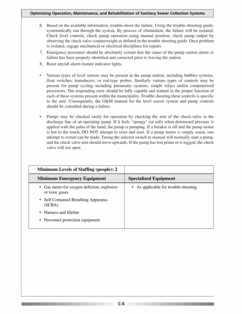
Optimizing Operation, Maintenance, and Rehabilitation of Sanitary Sewer Collection Systems
6. Based on the available information, trouble-shoot the failure. Using the trouble-shooting guide, systematically run through the system. By process of elimination, the failure will be isolated. Check level controls, check pump operation using manual position, check pump output by observing the check valve counterweight as defined in the trouble shooting guide. Once problem is isolated, engage mechanical or electrical disciplines for repairs
7. Emergency personnel should be absolutely certain that the cause of the pump station alarm or failure has been properly identified and corrected prior to leaving the station.
8. Reset any/all alarm feature indicator lights.
• Various types of level sensors may be present in the pump station, including bubbler systems, float switches, transducers, or rod-type probes. Similarly various types of controls may be present for pump cycling including pneumatic systems, simple relays and/or computerized processors. The responding crew should be fully capable and trained in the proper function of each of these systems present within the municipality. Trouble shooting these controls is specific to the unit. Consequently, the O&M manual for the level sensor system and pump controls should be consulted during a failure.
• Pumps may be checked easily for operation by checking the arm of the check-valve in the discharge line of an operating pump. If it feels "spongy" (or soft) when downward pressure is applied with the palm of the hand, the pump is pumping. If a breaker is off and the pump motor is hot to the touch, DO NOT attempt to reset and start. If a pump motor is simply warm, one attempt to restart can be made. Turing the selector switch to manual will normally start a pump, and the check valve arm should move upwards. If the pump has lost prime or is lugged, the check valve will not open.
Minimum Levels of Staffing (people): 2
Minimum Emergency Equipment Specialized Equipment
• Gas meter-for oxygen deficient, explosive or toxic gases
• Self Contained Breathing Apparatus (SCBA)
• Harness and lifeline
• Personnel protection equipment
• As applicable for trouble-shooting
C-6

Appendix C: Emergency Procedures
PROBLEM: Pumping Station Failure Caused by Force-Main Break Inside the Drywell, Pump or Valve Failure. (Wetwell/Drywell Type Station)
EMERGENCY PROCEDURES:
• Dispatch pumping station crew to the pumping station immediately.
• Upon arrival the crew should identity if the drywell and wetwell are flooded. The pumps may be still pumping if the motor is located at floor level and the pumps are on the lower level or if drypit submersibles were installed.
• After further investigation, the crew should determine the nature of the failure, i.e. pump(s), valve(s) or force main(s) if possible prior to entering the drywell.
• Call additional crew to bring appropriate portable pump(s) including all required lengths of suction and discharge house, to the pumping station.
• Before entering the drywell, measure the atmospheric conditions for sufficient oxygen and the presence of explosive or toxic gases. Remove all hazards as appropriate prior to entering station (including electrical and engulfment hazards).
• Constantly monitor the atmospheric conditions while working in the drywell of the station.
• Upon arrival of the portable pump, connect the appropriate lengths of suction hose that will suspend well into the wetwell, and then connect enough discharge hose to pump into bypass connection.
• Lock out and tag out (LOTO) the main line, disconnect (if applicable).
• Set up an additional portable trash pump to pump out the drywell into the wetwell.
• Enter drywell and inspect the following facilities: Lighting Ventilation Sump pump operation Motor control system including air compressors Auxiliary power systems and controls Bubbler system (if applicable) Pump alternator or processor Control and instrument readings MCC failure indicators Temperature of pump motors All internal piping
• Isolate the failed component by valve operation. Start the auxiliary pump and motor, if possible (after exiting the drywell). Shut down bypass operation if possible.
• Complete repairs to pipe, pump or valve as per policy. If permanent materials are not readily available, install blind flanges for temporary conditions. If auxiliary systems associated with the permanent station are in operation, LOTO prior to installing repaired components.
C-7

Optimizing Operation, Maintenance, and Rehabilitation of Sanitary Sewer Collection Systems
• Restore facilities to normal and inspect other components of the force main and pumping system for signs of similar failure.
• Shut down bypass operation. Do not disconnect hoses until repair is checked for leaks. Operate pumps to check repair under pressure and normal operating conditions.
• If no leaks are observed, return pumps to normal conditions by removing LOTO. Monitor pumps to check lead/lag operations.
• Proceed to wetwell for inspection. Before entering the wetwell, measure the atmospheric conditions for sufficient oxygen and the presence of explosive or toxic gases. Check the following as facilities applicable:
Lighting Ventilation Wetwell level Bar rack and/or comminutor (if applicable) Float controls/level sensors Grease assessment
• Make out a report indicating; the time of the call, description of the problem, how the repair was made, personnel present and equipment used.
• If sewage bypassed the collection system, file DEP Bypass Notification Log and Bypass Report Form as required by NPDES Permit.
Minimum Levels of Staffing (people): 2–4
Minimum Emergency Equipment Specialized Equipment
• Harness and lifeline
• Flash light
• Emergency lighting
• Portable pumps and hoses
• Miscellaneous tools
• Personal protection equipment
• Gas meter-for oxygen deficient, explosive or toxic gases
• Self Contained Breathing Apparatus (SCBA)
C-8

Appendix C: Emergency Procedures
PROBLEM: Pumping Station Failure Caused by Force-Main Break Inside Valve Pit, Pump or Valve Failure. (Submersible Type Application)
EMERGENCY PROCEDURES:
• Dispatch pumping station crew to the pumping station immediately.
• Upon arrival the crew should identity the storage capacity in the wetwell. This will give some indication of the time available for response.
• Inspect the motor control circuit looking for failure indications. Check processor to determine failure if applicable. If pump failure is determined, skip to wetwell inspection steps.
• Inspect the valvepit. Observe all valves and force mains. If flooded, arrange to pump out the valve pit. If failure within the valvepit is detected, skip to bypass steps.
• Prior to viewing the wetwell, measure the atmospheric conditions for sufficient oxygen and the presence of explosive or toxic gases. If flooded, skip to bypass steps.
• Constantly monitor the atmospheric conditions while working in or above the wetwell. Inspect the wetwell. Check the wetwell floats or level control system, bar rack and pump volute are for clogging or other problems.
Bypass Steps
• If pump failure, determine if bypass pumping is necessary. If unnecessary skip to repair procedures.
• Bypass pump. Call additional crew to bring appropriate portable pump(s) including all required lengths of suction and discharge house, to the pumping station if necessary. Upon arrival of the portable pump, connect the appropriate lengths of suction hose that will suspend well into the wetwelll, and then connect enough discharge hose to pump into appropriate manhole or bypass connection (if so equipped). Go through the procedures for starting the portable pump, and begin pumping.
Repair Steps
• Lock out and tag out (LOTO) the main line, disconnect (if applicable).
• If pump station valve pit is flooded, pump out the valve pit with portable trash pump as necessary to effect repairs.
• Enter valve pit or wet well and inspect the piping and valves for cause of failure. (Monitor the atmospheric conditions for sufficient oxygen and the presence of explosive or toxic gases).
• Complete repairs to pipe, pump or valve as per policy. If permanent materials are not readily available, install temporary repairs until the permanent repairs can be completed.
• Restore facilities to normal and inspect other components of the force main and pumping system for signs of similar failure.
C-9

Optimizing Operation, Maintenance, and Rehabilitation of Sanitary Sewer Collection Systems
• Shut down bypass operation. Do not disconnect hoses until repair is checked for leaks. Operate pumps to check repair under pressure and normal operating conditions.
• If no leaks are observed, return pumps to normal conditions by removing LOTO. Monitor pumps to check lead/lag operations.
• Make out a report indicating; the time of the call, description of the problem, how the repair was made, personnel present and equipment used.
• File DEP Bypass Notification Log and By-Pas Report Form as required by NPDES Permit.
NOTES:
1. Permit(s) must be obtained from the Long Island Sound Program if there is to be any work in a tidal wetland area.
Minimum Levels of Staffing (people): 2–4
Minimum Emergency Equipment Specialized Equipment
• Harness and lifeline
• Flash light
• Emergency lighting
• Portable pumps and hoses
• Gas meter-for oxygen deficient, explosive or toxic gases
• Personal protection equipment
• Self Contained Breathing Apparatus (SCBA)
C-10

Appendix C: Emergency Procedures
PROBLEM: Pumping Station Failure Caused by Secondary Power Failure During Power Outage
EMERGENCY PROCEDURES:
• Dispatch pumping station crew to the pumping station immediately. The crew needs to bring the auxiliary generator for that specific station as a backup assuming that repair to the dedicated generator is untimely.
• Dispatcher shall request the assistance of the power company in restoring power to the station if necessary. Determine the estimated time of arrival of the power company crew and then notify the pumping station operators.
• Pumping station operators should check the overhead power lines for fuses that might have blown or down power lines as they approach the pumping station. If the operators notice a blown fuse or down power line, identify the pole number(s), and notify the dispatcher to relay to the power company the location and the pole number(s).
• Lock out and tag out (LOTO) the main line, disconnect (if applicable).
• Check all components of dedicated generator to determine failure cause. Utilize manufacturer prepared trouble-shooting guide to aid in diagnosis. If unrepairable immediately, connect the portable generator to the auxiliary power connection located outside the building. Examine plug type and ensure consistency. Use adapters as necessary.
• Go through the specific procedures for starting the generator to supply power to the station.
• Obtain the services of a qualified generator repair facility to address the dedicated generator failure.
• Once fully repaired, disconnect the portable generator and reconnect the dedicated unit. Operate the dedicated unit through several pump cycles. Check unit for regular exercise.
Minimum Levels of Staffing (people): 2–3
Minimum Emergency Equipment Specialized Equipment
• Harness and lifeline
• Flash light
• Emergency lighting
• Portable generator
• Personal protection equipment
• Gas meter-for oxygen deficient, explosive or toxic gases
• Power testing equipment
C-11

This page is intentionally blank.

Appendix C: Emergency Procedures
PROBLEM: Sewer Blockage or Surcharging into Basement
EMERGENCY PROCEDURES:
• Dispatch the sewer crew to the complainant address immediately.
• If the flow is questionable (not reasonable for the given service area) go to the upstream manhole to visually compare flows.
• If the flow from both manholes is reasonable for the area, notify the property owners that the problem is in their service lateral and to contact a plumber or sewer service contractor to relieve the blockage.
• Refer to sewer maps for location of sewers (private lands, flow patterns, manholes, etc.) and determine if the area is served by a pump station, before responding to the call.
• If the area of complaint is served by a pump station, check to see if any alarms from the pump station have been received at the WPCF.
• Notify the property owner you are on the site, upon arrival.
• Check flow in downstream manhole from the complaint location.
• Install the proper size sandtrap in the downstream invert of the manhole before clearing the blockage to capture the debris. From the debris collected try to determine the cause of the blockage and remove the debris from the manhole.
• Use the necessary equipment to relieve the blockage, either by jet flushing or power rodding.
• If the downstream manhole is flowing full, continue checking manholes downstream until a dry manhole is found. Clear blockage upstream from the dry manhole.
• Notify supervisor and describe the bypass. The supervisor will notify the proper authorities and agencies: (See notification charts)
• If the blockage is in city/town main line, relieve the blockage, clean up the property owner’s basement as per policy and spray an industry standard disinfectant. If blockage is determined to be in property owner’s lateral connection, direct property owner to his/her responsibility to clear.
• Make out a report indicating; the time of the call, description of the problem, how the repair was made, personnel present and equipment used.
• If sewage bypassed the collection system, file DEP Bypass Notification Log and Bypass Report Form as required by NPDES Permit.
C-13

Optimizing Operation, Maintenance, and Rehabilitation of Sanitary Sewer Collection Systems
NOTES:
1. I nstall the proper size sandtrap in the downstream invert of the manhole before clearing the blockage to capture the debris. From the debris collected try to determine the cause of the blockage and remove the debris from the manhole.
2. Record the water damage to all items in the basement. Record all actions taken (from start to finish) in log/record book, including equipment and personnel that were utilized.
Minimum Levels of Staffing (people): 2
Minimum Emergency Equipment Specialized Equipment
• Jet flushing unit if available (sand trap)
• Rodding machine & associated cleaning/cutting attachments (sand trap)
• Standard harness and lifeline if applicable
• Air blower with hose
• Power vacuum
• Portable pumps
• Portable generators
• Safety cones/barricades
• Gas meter – for oxygen deficient, explosive or toxic gases
• Confined space entry tripod and associated equipment
• Television
• Truck with hoist
• Vactor unit
• Power saw (circular)
• Pipe cutter (hydraulic)
• Caution tape
• Sand trap
• Self Contained Breathing Apparatus (SCBA)
C-14

Appendix C: Emergency Procedures
STEPS TO BE TAKEN BY PROPERTY OWNERS WHEN SEWAGE BACK-UP OCCURES
Call and report stoppage. Use phone numbers listed for WPCF at night. The WPCF will check the main sewer for blockage. If the main sewer is blocked the WPCF will clear it. If the main sewer is clear then the property owner must hire a licensed plumber, drain layer, or sewer cleaner to free any blockage, which might exist in their lateral. The property owner is responsible to pay for this activity.
NOTE: PROPER RODDING PROCEDURE GUIDELINE
In cases where a property owner needs to free a blockage within their lateral, the following procedures shall be implemented. The plumber shall use a 4" cutter at the end of the rod. If the plumber relieves the blockage, he shall then rod the house connection to the main sewer line.
If the blockage is found in the portion of the sewer house connection located within private property, the owner must hire a licensed contractor to perform the necessary repair work, under permit and inspection from the local WPCF.
All repair work on the sewer house connection must be performed under permit issued by the WPCF to a licensed contractor, and will be inspected by the local WPCF personnel.
RODDINGS:
If the property owner, licensed plumber, drain layer on sewer cleaner does not call the WPCF and request the main sewer check prior to rodding. The WPCF will not assume liability if the problem is located in he main sewer.
If there is a blockage, but no record of the house connection, the owner must prove where the blockage is located. This can be done by excavation or electronic locator in he presence of an inspector.
The WPCF requires proper rodding procedures. The rodder must use a 4" cutter. If he can’t break through the blockage, he will then start using smaller cutters back up to 4". He will then push the blockage into the main sewer.
C-15

This page is intentionally blank.

Appendix C: Emergency Procedures
PROBLEM: Overflowing Sewer Manhole Resulting from Surcharged Trunk Sewer (No backup into building)
EMERGENCY PROCEDURES:
• Dispatch the sewer crew immediately to the problem location.
• Refer to sewer maps for location of sewers (private lands, flow patterns, manholes, etc.) and determine if the area is served by a pump station, before responding to the call.
• Go to the location of the overflowing manhole to access the immediate danger to the environment.
• Determine the location of the blockage by inspecting the downstream manholes until a dry manhole is found.
• Install the proper size sandtrap in the downstream invert of the manhole before clearing the blockage to capture the debris. From the debris collected try to determine the cause of the blockage and remove the debris from the manhole.
• Use the necessary equipment to relieve the blockage, either by jet flushing or power rodding.
• If it is imminent that the waste water will be released into wetlands receiving waters or a drinking water supply watershed, then the supervisor should be notified. The supervisor will notify the proper authorities and agencies: (See notification charts)
• Call in additional crews to set up flotation booms across streams, brooks, bypass pumping, etc., as necessary. Unless special conditions exist, freeing the blockage is the priority before containing the bypass.
• Gather and remove sewage related debris and organic matter from the affected area.
• If the waste water is in the streets/roads (public or private), then contain the waste water as best as possible with sand bags or other industry accepted alternatives to minimize any impact to public health or the environment.
• Sandbag nearby catch basin inlets or paved leak-offs to prevent the waste water from entering the drainage system and causing potential contamination to the tributary receiving waters.
• If ponding should occur on the street or easement (public or private), cordon off the area.
• Remove as much of the sewage as possible.
• Disinfect the ponding areas with an industry standard disinfectant and notify the surrounding homes.
• If the waste water should jeopardize a playground or park, cordon off the entire area. Close the park to the public until the issue has been remedied to the satisfaction of the local and state boards of health and the local park superintendent.
C-17

Optimizing Operation, Maintenance, and Rehabilitation of Sanitary Sewer Collection Systems
• Make out a report indicating; the time of the call, description of the problem, how the repair was made, personnel present and equipment used.
• If sewage bypassed the collection system, file DEP Bypass Notification Log and Bypass Report Form as required by NPDES Permit.
NOTE:
1. Permit(s) must be obtained from the Long Island Sound Program if there is to be any work in a tidal wetland area.
Minimum Levels of Staffing (people): 2-3
Minimum Emergency Equipment Specialized Equipment
• Jet flushing unit if available (sand trap)
• Rodding machine & associated cleaning/cutting attachments (sand trap)
• Standard disinfectants
• Safety harness and lifeline if applicable
• Air blower with hose
• Power vacuum
• Portable pumps
• Portable generators
• Safety cones/barricades
• Gas meter-for oxygen deficient, explosive or toxic gases
• Confined space entry tri-pod and associated equipment
• TV camera unit
• Truck with hoist
• Vactor unit
• Power saw (circular)
• Pipe cutter (hydraulic)
• Caution tape
• Sand trap
• Flotation booms if necessary
• Self Contained Breathing Apparatus (SCBA)
C-18

Appendix C: Emergency Procedures
PROBLEM: Sewage Force-Main Break (residential neighborhood)
EMERGENCY PROCEDURES:
• Dispatch a sewer crew to the site to assess the immediate danger to the environment and to determine who and what might be affected.
• Refer to the sewer maps for location of sewers (private lands flow patterns, manholes, etc.) and determine if the area is served by a pump station, before responding to the call.
• Request additional manpower and equipment as needed based on initial damage assessment (e.g. excavating crew, bypass pumping equipment, etc.).
• Bypass pumping from the pump station wetwell to the force main discharge manhole may be required. If necessary, set up bypass pumping equipment.
• Call in additional crews to set up flotation booms across streams, brooks, sandbagging, etc., as necessary. Unless special conditions exist, bypassing the broken force main is a priority before containing the bypass.
• Gather and remove sewage related debris and organic matter from the affected area.
• If the waste water is in the streets/roads (public or private), then contain the waste water as best as possible with sand bags or other industry accepted alternatives to minimize any impact to public health or the environment.
• Sandbag nearby catch basin inlets or paved leak-offs to prevent the waste water from entering the drainage system and causing potential contamination to the tributary receiving waters.
• If ponding should occur on the street or easement (public or private), cordon off the area.
• Remove as much of the sewage as possible.
• Disinfect the ponding areas with an industry standard disinfectant and notify the surrounding homes.
• If the waste water should jeopardize a playground or park, cordon off the entire area. Close the park to the public until the issue has been remedied to the satisfaction of the local and state boards of health and the local park superintendent.
• After the bypass pumping equipment is at the site and in place, lock-out and tag-out (LOTO) the pumps in the pumping station.
• Draw down the wetwell as much as possible and maintain low level.
• Drain the force-main by first closing down the gate valve on the upstream side of the discharge check valve in the pumping station.
• Open the check valve by hand and secure it in place.
C-19
Optimizing Operation, Maintenance, and Rehabilitation of Sanitary Sewer Collection Systems
• Slowly bleed the force-main back into the wetwell by slowly opening the gate valve on the discharge side of the pump, but only to the point where the force-main stops leaking and there is enough room to make the repair. Constant communication must take place between the crew located at the break and the crew located at the pump station.
• Close the gate valve and return the check valve to its normal operating position and then fully open the gate valve.
• Repair force main break as per policy.
• After the repair is complete, remove LOTO and return the pumps to normal operating position.
• Run the pump in the hand manual position to fill the force-main. Once completed, observe several pumping cycles before completely back-filling the excavation.
• Upon confirmation of adequacy of the repair, backfill the excavation (if necessary) and restore surface conditions to match existing conditions.
• While the crew is restoring the excavation, the crew leader should conduct a preliminary assessment of damage to private and public property. The crew leader should take appropriate still photographs and video footage; if possible, of the outdoor area of the sewer over flow and impacted area to thoroughly document the nature and extent of the impacts.
• Make out a report indicating,; the time of the call, description of the problem, how the repair was made, personnel present and equipment used.
• If sewage bypassed the collection system, file DEP Bypass Notification Log and Bypass Report Form as required by NPDES Permit.
NOTE:
1. Permit(s) must be obtained from the Long Island Sound Program if there is to be any work in a tidal wetland area.
C-20

Appendix C: Emergency Procedures
Minimum Levels of Staffing (people): 4
Minimum Emergency Equipment Specialized Equipment
• Jet flushing unit if available (sand trap)
• Rodding machine & associated cleaning/cutting attachments (sand trap)
• Standard disinfectants
• Safety harness and lifeline if applicable
• Air blower with hose
• Power vacuum
• Portable pumps
• Portable generators
• Safety cones/barricades
• Gas meter-for oxygen deficient, explosive or toxic gases
• Confined space entry tri-pod and associated equipment
• TV camera unit
• Truck with hoist
• Vactor unit
• Power saw (circular)
• Pipe cutter (hydraulic)
• Caution tape
• Sand trap
• Flotation booms if necessary
• Self Contained Breathing Apparatus (SCBA)
C-21

This page is intentionally blank.

Appendix C: Emergency Procedures
PROBLEM: Sewage Force-Main Break (cross country easement non-residential area)
EMERGENCY PROCEDURES:
• Dispatch a sewer crew to the site to assess the immediate danger to the environment and to determine who and what might be affected.
• Refer to the sewer maps for location of sewers (private lands flow patterns, manholes, etc.) and determine if the area is served by a pump station, before responding to the call.
• Request additional manpower and equipment as needed based on initial damage assessment (e.g. excavating crew, bypass pumping equipment, etc.)
• Bypass pumping from the pump station wetwell to the force main discharge manhole may be required. If necessary, set up bypass pumping equipment.
• If bypass pumping is not an option, then the line may need to be repaired under pressure. Shut down the pumping station only if detention time is known and can be mitigated.
• Call in additional crews to set up flotation booms across streams, brooks, sandbagging, etc., as necessary. Unless special conditions exist, bypassing the broken force main is a priority before containing the bypass.
• The crew shall initiate measures to contain the sewer overflow as best as possible, cordon off the affected area and place absorbing booms or sand bags to collect any floatable debris.
• Check the tributary area to determine if the discharge will affect any receiving waters.
• If it is determined that the receiving water may be affected, and then the dispatcher should notify the proper authorities or agency.
• If the break is on the pipe length, then a repair can be made with a wrap-around sleeve. If the break is at the bell, then a bell-joint clamp may be used.
• If a repair cannot be made while the line is under pressure or bypass pumping cannot be completed, then only two (2) alternatives exist:
1. Utilize a vactor tuck to remove the water from the wetwell. Discharge the water into a manhole in a different tributary area or at the treatment plant.
2. If the vactor truck has insufficient volume, the scenario may require the assistance of several tanker trucks or the use of a fractionalization tank to perform this function.
• Refer to the force-main break in residential neighborhood and follow the procedure for draining the force-main and returning the pumping station to normal operating procedures.
• Upon confirmation of adequacy of the repair, backfill the excavation (if necessary) and restore surface conditions to match existing conditions.
C-23

Optimizing Operation, Maintenance, and Rehabilitation of Sanitary Sewer Collection Systems
• While the crew is restoring the excavation, the crew leader should conduct a preliminary assessment of damage to private and public property. The crew leader should take appropriate still photographs and video footage; if possible, of the outdoor area of the sewer over flow and impacted area to thoroughly document the nature and extent of the impacts.
• Make out a report indicating,; the time of the call, description of the problem, how the repair was made, personnel present and equipment used.
• If sewage bypassed the collection system, file DEP Bypass Notification Log and Bypass Report Form as required by NPDES Permit.
NOTE:
1. Permit(s) must be obtained from the Long Island Sound Program if there is to be any work in a tidal wetland area.
Minimum Levels of Staffing (people): 4
Minimum Emergency Equipment Specialized Equipment
• Jet flushing unit if available (sand trap)
• Rodding machine & associated cleaning/cutting attachments (sand trap)
• Standard disinfectants
• Safety harness and lifeline if applicable
• Air blower with hose
• Power vacuum
• Portable pumps
• Portable generators
• Safety cones/barricades
• Gas Meter-for oxygen deficient, explosive or toxic gases
• Confined space entry tri-pod and associated equipment
• TV camera unit
• Truck with hoist
• Vactor unit
• Power saw (circular)
• Pipe cutter (hydraulic)
• Caution tape
• Sand trap
• Flotation booms if necessary
• Self Contained Breathing Apparatus (SCBA)
C-24

Appendix C: Emergency Procedures
PROBLEM: Sewer Main Break/Collapse
EMERGENCY PROCEDURES:
• Dispatch sewer crew to location of break/collapse immediately.
• Set up signs, barricades, and/or barrels for traffic control and public safety.
• Reroute traffic as necessary. Deploy traffic control measures such as, police or flag person as needed.
• Request additional manpower and equipment as needed based on initial damage assessment (e.g. excavating crew, bypass pumping equipment, etc.).
• Bypass pumping from the upstream manhole to the downstream manhole may be required. If necessary, set up bypass pumping equipment. If not necessary, prepare for repairs while the pipe is flowing.
• Call in additional crews to set up flotation booms across streams, brooks, sandbagging, etc., as necessary. Unless special conditions exist, bypassing the failed sewer main is a priority before containing the bypass.
• Gather and remove sewage related debris and organic matter from the affected area.
• If the waste water is in the streets/roads (public or private), then contain the waste water as best as possible with sand bags or other industry accepted alternatives to minimize any impact to public health or the environment.
• Sandbag nearby catch basin inlets or paved leak-offs to prevent the waste water from entering the drainage system and causing potential contamination to the tributary receiving waters.
• If ponding should occur on the street or easement (public or private), cordon off the area.
• Remove as much of the sewage as possible.
• Disinfect the ponding areas with an industry standard disinfectant and notify the surrounding homes.
• If the waste water should jeopardize a playground or park, cordon off the entire area. Close the park to the public until the issue has been remedied to the satisfaction of the local and state boards of health and the local park superintendent.
• Determine the location of the break/collapse and make any necessary repairs. Use repair procedures consistent with policy. If the break is on the pipe length, then a repair can be made with a wrap-around sleeve. If the break is at the bell, then a bell-joint clamp may be used.
• Upon confirmation of adequacy of the repair, backfill the excavation (if necessary) and restore surface conditions to match existing conditions.
C-25

Optimizing Operation, Maintenance, and Rehabilitation of Sanitary Sewer Collection Systems
• To restore the sewer line to full capacity, the crew should remove any debris that may have entered and accumulated in the sewer line downstream and upstream from the break/collapse. The crew should clean the sewer line as described below.
• Install the proper size sandtrap in the downstream invert of the downstream manhole to trap any debris, which may have, accumulated in the sewer line.
• Using a high velocity jet-flushing vehicle, begin flushing from the downstream manhole against the flow to the upstream manhole.
• Repeat this procedure for several upstream and downstream pipe reaches.
• The crew leader should take appropriate still photographs and video footage; if possible, of the outdoor area of the sewer over flow and impacted area to thoroughly document the nature and extent of the impacts.
• Make out a report indicating; the time of the call, description of the problem, how the repair was made, personnel present and equipment used.
• If sewage bypassed the collection system, file DEP Bypass Notification Log and Bypass Report Form as required by NPDES Permit.
NOTE:
1. Permit(s) must be obtained from the Long Island Sound Program if there is to be any work in a tidal wetland area.
Minimum Levels of Staffing (people): 4
Minimum Emergency Equipment Specialized Equipment
• Jet flushing unit if available (sand trap)
• Rodding machine & associated cleaning/cutting attachments (sand trap)
• Standard disinfectants
• Safety harness and lifeline if applicable
• Air blower with hose
• Power vacuum
• Portable pumps
• Portable generators
• Safety cones/barricades
• Gas meter-for oxygen deficient, explosive or toxic gases
• Confined space entry tri-pod and associated equipment
• TV camera unit
• Truck with hoist
• Vactor unit
• Power saw (circular)
• Pipe cutter (hydraulic)
• Caution tape
• Sand trap
• Flotation booms if necessary
• Self Contained Breathing Apparatus (SCBA
C-26

Appendix C: Emergency Procedures
PROBLEM: Air Release and Vacuum Relief Valve Failure
EMERGENCY PROCEDURES: • These valves require frequent inspection and maintenance. Their failure is often found during
routine inspections. Both these valves may fail to operate reliably if grease is allowed to accumulate in the valve or on the operating mechanism.
• Inspection crew should inspect valves in accordance with the specific manufacture’s recommendations.
• Attach fittings at the top and the bottom to permit back flushing of all valves upon initial installation.
• Isolate the valve from the force-main by closing the shutoff valve attached to the force-main.
• To clean the internal components of the valve(s), attach a backflusing hose to a pressurized water source using a quick disconnect coupling.
• Place a blow off discharge hose in a container to collect the backflush water from the blow off valve. This is waste water that should not be discharged onto the street or into the valve pit.
• Open the shutoff valve and backflush the valve through the blow off valve at the bottom.
• If you are using a potable (drinking) water source, provide the system with an anti-siphon device or back flow to prevent contamination of the potable water.
• Make out a report indicating; the time of the call, description of the problem, how the repair was made, personnel present and equipment used.
• If sewage bypassed the collection system, file DEP Bypass Notification Log and Bypass Report Form as required by NPDES Permit.
Minimum Levels of Staffing (people): 3
Minimum Emergency Equipment Specialized Equipment
• Jet flushing unit if available (sand trap)
• Rodding machine & associated cleaning/cutting attachments (sand trap)
• Standard disinfectants
• Safety harness and lifeline if applicable
• Air blower with hose
• Power vacuum
• Portable pumps
• Portable generators
• Safety cones/barricades
• Gas meter-for oxygen deficient, explosive or toxic gases
• Confined space entry tri-pod and associated equipment
• TV camera unit
• Truck with hoist
• Vactor unit
• Power saw (circular)
• Pipe cutter (hydraulic)
• Caution tape
• Sand trap
• Flotation booms if necessary
• Self Contained Breathing Apparatus (SCBA)
C-27

This page is intentionally blank.

Appendix C: Emergency Procedures
PROBLEM: Cavities and Depressions in Streets and Lawns
EMERGENCY PROCEDURES:
• When a call is received from the public, confirm the following:
1. The location is in fact a cavity or depression and not a missing manhole cover, gate box cover or catch basin grate.
2. The location is not a high or low manhole casting or gate box. If there is any question as to whether or not it is a cavity or problem with a casting, check the location at a convenient time.
3. Advise the caller that the problem will be taken care of.
4. Obtain the location of the reported cavity and if possible the name and address of the party making the call.
• If the caller indicates the problem is severe, extensive or obviously associated with the sewer or water system, investigate and barricade the condition if it appears appropriate to do so. If the situation is dangerous, protect it with lights and barricades. Notify water company immediately to aid in the cause investigation.
• When checking a depression over a main sewer, it is important to check the main sewer at both the upstream and downstream manholes adjacent to the depression to determine if there is a restriction of flow. If there is a blockage, it may indicate a possible main sewer break.
• If the cavity is a result of a sewer failure, refer to procedures for sewer main collapse and repair as appropriate.
• If it has been determined that it is a cavity or depression caused by other utilities (storm drain, water main, etc.), the crew leader will notify the city/town’s Highway Department, and request that the cavity or depression be barricaded.
• The crew leader should take appropriate still photographs and video footage; if possible, of the outdoor area of the sewer over flow and impacted area to thoroughly document the nature and extent of the impacts.
• Make out a report indicating; the time of the call, description of the problem, how the repair was made, personnel present and equipment used
• If sewage bypassed the collection system, file DEP Bypass Notification Log and Bypass Report Form as required by NPDES Permit.
C-29

Optimizing Operation, Maintenance, and Rehabilitation of Sanitary Sewer Collection Systems
Minimum Levels of Staffing (people): 1
Minimum Emergency Equipment Specialized Equipment
• Barrels
• Barricades with flashing lights
• Flash light
• Safety cones
• Personal protection equipment
• Hard hats, etc.
C-30

Appendix D: House Lateral Design Standards
APPENDIX D HOUSE LATERAL DESIGN STANDARDS
This appendix contains generic house lateral design standards. These generic standards can be adapted to fit specific community needs. They are not presented as inclusive of all situations or circumstances.
TOWN OF XXXXXX STANDARDS FOR
DESIGN AND CONSTRUCTION OF BUILDING SEWERS
Includes all amendments through ____________________ Be it so voted and enacted by the Board of Selectmen, Acting as Sewer Commissioners of the
Town of XXXXXX, Commonwealth of Massachusetts as follows:
True Copy Attest:______________________________________________________________ Town Clerk
DEFINITIONS D-3 1.0 PURPOSE D-5 2.0 APPLICABILITY D-5 3.0 DEP EXTENSION/CONNECTION PERMIT D-5
3.10 Paper Streets D-6 4.0 BUILDING SEWER CONNECTION PERMIT D-6
4.10 Connection Permits D-6 4.20 Permit Fee D-6 4.30 Entrance Fee D-6 4.35 Street Opening Permit D-6 4.40 Application for Local Permit D-7 4.50 Eligibility D-8 4.60 Expiration of Permit D-8 4.70 Notice of Violation D-8 4.80 Mandatory Inspection of Building Connections D-9 4.90 Right of Entry D-9
5.0 TRENCH EXCAVATION & BACKFILL D-10 5.05 Traffic Control & Safety D-10 5.10 Scope D-10 5.20 Materials D-10 5.21 Trench Backfill D-10 5.22 Crushed Stone D-11 5.23 Gravel for Trench Backfill D-11 5.24 Bituminous Concrete D-11 5.25 Controlled Density Fill D-11
6.0 GENERAL CONSTRUCTION D-11 6.11 Clearing the Right-of-Way D-11 6.12 Pavement Removal and Replacement D-11 6.13 Blasting D-12 6.14 Trench Width D-12
D-1
Optimizing Operation, Maintenance, and Rehabilitation of Sanitary Sewer Collection Systems
6.15 Grade 6.16 Shoring, Sheeting & Boxing of Trenches 6.17 Location of Excavated Materials 6.18 Removal of Water 6.19 Trench Backfill Compaction 6.20 Excess Excavated Material 6.21 Rock Excavation 6.22 Controlled Density Fill
7.0 SEWER PIPE INSTALLATION 7.10 Scope 7.20 Materials
8.0 INSTALLATION REQUIREMENTS 8.10 Permit 8.20 Licensed Contractors 8.30 Minimum Size, Fittings and Clean-outs 8.40 Minimum Elevations for Gravity Connection 8.50 Future Connections 8.60 Grease Traps
9.0 WORKMANSHIP 9.10 Preparation of Trench 9.20 Preparation of Sewer Pipe 9.30 Laying and Jointing Pipe and Fittings 9.35 Sewer Installation
10.0 VACUUM TEST 10.10 Preparation of the Manhole 10.20 Procedure
11.0 MANHOLE AND CLEANOUT CONSTRUCTION 11.10 Scope 11.20 Materials 11.21 Concrete 11.22 Precast Manhole Sections 11.23 Precast Concrete Bases 11.24 Special Fittings 11.25 Manhole Frames & Covers 11.26 Manhole Steps 11.27 Manhole Blockouts/Plugged Boot 11.28 Manhole Tables 11.29 Manhole Inverts 11.30 Drop Manholes
12.0 GRINDER PUMPS & SEWERAGE EJECTORS 12.10 Force Main Connections
13.0 SEWER EASEMENTS 14.0 PROTECTION OF WATER SUPPLY
14.10 Well Areas-Zone II 15.0 PIPE JACKING & DIRECTIONAL DRILLING
15.10 Pipe Jacking 15.20 Horizontal Directional Drilling 15.25 Boring Path Report 15.30 Vacuum Holes
16.0 VALIDITY
D-12 D-12 D-12 D-13 D-13 D-13 D-13 D-13 D-14 D-14 D-14 D-15 D-15 D-15 D-15 D-16 D-16 D-16 D-16 D-16 D-17 D-17 D-17 D-18 D-18 D-19 D-19 D-19 D-19 D-19 D-19 D-19 D-19 D-19 D-20 D-20 D-20 D-20 D-20 D-20 D-21 D-21 D-22 D-23 D-23 D-23 D-23 D-23 D-23 D-24
D-2

Appendix D: House Lateral Design Standards
DEFINITIONS:
Appurtenance shall mean any piece associated with the physical operation of the XXXXXX Sewerage System.
ASTM shall mean the material standard of the American Society for Testing and Materials.
Authority shall mean the Massachusetts Water Resources Authority.
Board shall mean the Board of Selectmen, acting as Sewer Commissioners, or their authorized agent.
Building Sewer shall mean the extension from the interior plumbing to the public sewer or other place of disposal. The building sewer extends from the foundation at the building to the property line.
CDF shall mean controlled density fill or flowable fill.
Concentric shall mean the relationship between two different circular, cylindrical sewer pipes, when one is exactly centered within the other.
DEP shall mean the Massachusetts Department of Environmental Protection.
Engineer shall mean any person who is licensed by the Commonwealth of Massachusetts to perform professional engineering services.
EPA shall mean the United States Environmental Protection Agency.
Garage shall mean any structure or property where one or more motor vehicles are kept, stored, or serviced, including a public or private garage, carport, motor vehicle repair shop, paint shop, service station, lubritorium, car wash, gasoline station with grease pits or wash racks or areas, or any building used for similar purposes.
Infiltration shall mean the water entering a Sewerage System from the ground or a water body, including through such means as, defective building drains and sewers, pipes, pipe joints, connections, or manhole walls.
Inflow shall mean the discharge into a Sewerage System, including service connections, from such sources including, but not limited to: roof leaders, cellars, yards, and area drains, foundation drains, sump pumps, Cooling Water discharges, drains from springs, and swampy areas, manhole covers, cross connections from Storm Sewers and Combined Sewers, catch basins, storm water, surface runoff, or street wash water.
Lot shall mean an area of land in one ownership, with definite boundaries used, or available for use, as the site of one or more buildings.
May is permissive; shall is mandatory.
MWRA shall mean the Massachusetts Water Resources Authority.
MWRA Service Area shall mean the area consisting of the following political subdivisions: Arlington, Ashland, Bedford, Belmont, Boston, Braintree, Brookline, Burlington, Cambridge, Canton, Chelsea, Dedham, Everett, Framingham, the north sewer district of Hingham, Holbrook, Lexington, Malden, Medford, Melrose, Milton, Natick, Needham, Newton, Norwood, Quincy, Randolph, Reading, Revere, Somerville, Stoneham, Stoughton, Wakefield, Walpole, Waltham, Watertown, Wellesley, Westwood, Weymouth, Wilmington, Winchester, Winthrop, and Woburn.
M.G.L. shall mean Massachusetts General Law.
Owner shall mean the person(s) holding fee simple title to a parcel, tract or lot of land, as shown by the record in the appropriate Land Registration Office, Registry of Deeds or Registry of Probate.
D-3

Optimizing Operation, Maintenance, and Rehabilitation of Sanitary Sewer Collection Systems
Paper Street shall mean any road, street or way not legally accepted as a public way by the Town of XXXXXX.
Person shall mean an individual or two or more individuals, or trust, or a group or association of individuals, having a common or undivided interest in a tract of land including a partnership or corporation.
Plans shall mean approved contract drawings, Town standards, working drawings, Detail sheets or exact reproductions thereof, which show the location, character, dimensions and details of the work to be done.
Public Sewer shall mean a sewer in which all owners of abutting properties have equal rights and is controlled by the Board of Selectmen acting as Sewer Commissioners, and maintained by the Public Works Superintendent.
Recorded shall mean recorded in the Registry of Deeds of Norfolk County, except that, as affecting registered land, it shall mean filed with the Recorder of The Land Court. (Section 81-L of Chapter 41, M.G.L.).
Right-of-Way shall mean the area that has been laid out for travel purposes.
Sanitary Sewer shall mean a Sewer that carries Sanitary Sewage and/or Industrial Wastes.
Sewage shall mean the spent water of a community, which may be a combination of liquid and water-carried Wastes from residences, commercial buildings, industrial facilities, and institutions, together with any groundwater, surface water, and/or storm water that may be present.
Sewer shall mean a pipe or conduit that carries Sewage.
Sewer Use Discharge Permit shall mean the permit required or issued jointly by the Authority and a Municipality for the discharge of industrial waste.
Sewerage System shall mean any device, equipment or works used in the transportation, pumping, storage, treatment, recycling, and reclamation of Wastewater and Industrial Wastes.
Shall is mandatory; may is permissive.
Slope shall mean the inclination of a trench bottom or a trench sidewall, expressed as a ratio of vertical distance to the horizontal distance. For example, a 3:1 slope shall rise or fall 3’ vertical feet in a distance of 1’ horizontal foot.
Solid Waste shall mean any unwanted or discarded solid material, consisting of putrecible or nonputrescible solid waste material, including garbage and rubbish.
Storm Drain or Storm Sewer shall mean a pipe or conduit for conveying ground, storm, or surface waters, roof and surface runoff, uncontaminated Cooling Water, and non-contact industrial process waters.
Subgrade shall mean the plane at the bottom of the subbase.
Superintendent shall mean the Superintendent of Public Works of the Town of XXXXXX, or his authorized deputy, agent or representative.
Surveyor shall mean any person who is registered by the Commonwealth of Massachusetts to perform professional land surveying services.
Town Engineer shall mean the Town Engineer of the Town of XXXXXX, or his duly authorized deputy, agent or representative.
D-4

Appendix D: House Lateral Design Standards
1.0 Purpose
These specifications are intended to protect the public health, safety and welfare and the environment and to ensure proper and safe operation of the XXXXXX Municipal Sewer System by regulating the direct and indirect discharge of wastewater and pollutants to the Sewerage System in accordance with 360 CMR 10.000, the XXXXXX Code Sewer Use and the Rules & Regulations relating to Private Sewers adopted by the Board of Selectmen on __________.
In the absence of code provisions or in amplification thereof, the materials and procedures as set forth in appropriate specifications shall apply:
• American Society of Testing Material (ASTM), and the Water Pollution Control Federation (WPCF) Manual of Practice No.7, “Operation and Maintenance of Wastewater Collection Systems”.
• American Society of Civil Engineers (ASCE), Manuals and Reports in Engineering Practice No.60, “Gravity Sanitary Sewer Design and Construction”.
The XXXXXX Public Works Superintendent shall, in the case of any discrepancies or questions, direct the Contractor accordingly.
2.0 Applicability
Every person who directly or indirectly discharges Wastewater to the Authority Sewerage System shall ensure that such discharge complies with 360 CMR 10.000. The requirements of 360 CMR 10.000 apply to direct discharges to the Authority Sewerage System and to discharges to the Authority Sewerage System through a municipal sewer.
3.0 DEP Extension/Connection Permit
No person shall connect to a Municipal Sewer System or an Authority Sewer, or construct, effect, modify, or maintain a Sewer extension or connection, without a sewer system connection permit issued by the Board of Selectmen acting as Sewer Commissioners, or extension/connection permit if required by DEP pursuant to M.G.L. c.21§ 43 and 314 CMR 7.00, 360 CMR 10.000 in where such a permit is required.
Permit requirements are published by the DEP, referenced by the application categories in the following table:
DEP Permit Application Categories: 310 CMR 4.00
BRP WP 13 Major Sewer Extension
BRP WP 14 Minor Sewer Extension; Connect w/Pump Station
BRP WP 17 Major Sewer Connection (≥ 50,000 gpd)
BRP WP 55 Industrial Wastewater
All sewer extensions shall have a plan prepared by a Registered Professional Engineer in the Commonwealth of Massachusetts. The Department of Environmental Protection (DEP) must approve the Sewer Extension before the Town will issue any Sewer Connection or Street Opening Permits.
D-5

Optimizing Operation, Maintenance, and Rehabilitation of Sanitary Sewer Collection Systems
3.10 Paper Streets
Paper Street Sewers and appurtenances shall comply with the Street and Sewer-Commissioners. All sewer design and construction work proposed or performed in paper streets, shall comply with the Town of XXXXXX Land Subdivision Regulations.
4.0 Building Sewer Connection Permit
4.10 Connection Permits
A Sewer Connection Permit shall be issued by the Town of XXXXXX Engineering Department for all repairs, modifications or connections to the XXXXXX Sewer System. In addition, Sewer Connection Permits are required for the expansion of any existing building connected to the system which requires alteration or retrofit of the existing sewer or any of its direct appurtenances.
All costs and expense(s) incident to the installation and connection of the building sewer shall be borne by the owner. The owner shall indemnify the Town from any loss or damage that may directly or indirectly be occasioned by the installation of the building sewer.
No unauthorized person shall maliciously, willfully or negligently break, damage, destroy, uncover, deface or tamper with any structure, appurtenance or equipment which is a part of the sewerage works. Any person violating this provision shall be subject to immediate arrest under charge of disorderly conduct. Please note DIGSAFE-1-888-344-7233.
4.20 Permit Fee
A fee of $50.00 per residential dwelling unit and a fee of $75.00 per non-residential unit shall be charged for each Permit. This permit includes up to three (3) inspections. Additional inspections, if required, due to defective workmanship or incomplete construction will be assessed a re-inspection fee of an equal amount.
4.30 Entrance Fee
An entrance fee of $300.00, shall be charged for any new single connection to the Sewer System. The fee shall be deposited in the Sewer Enterprise Fund.
4.35 Street Opening Permit
Contractor shall obtain a Street Opening Permit from the Department of Public Works. If construction of the building sewer requires construction in a traveled way of a street or work within the Right of Way. The contractor shall post a bond in an amount determined by the Public Works Superintendent; said bond to be released only on final approval from the Superintendent of Public Works. The Contractor shall restore the street trench with a temporary patch of bituminous concrete within twenty-four (24) hours. If flowable fill was placed in a trench, subsequent trench repair is to be placed within thirty (30) days of the temporary patch.
D-6

Appendix D: House Lateral Design Standards
4.40 Application for Local Permit
1. A Permit application for any sewer extension must be made on the form prescribed by the Town of XXXXXX Engineering Department. Once a signed permit from the XXXXXX Engineering Department has been issued to the contractor, the entrance fee shall be paid to the P.W.D. where applicable. A Street Opening Permit must be obtained from the Public Works Department wherever a street is to be opened, or pursuant to the following:
a. Any easements required for construction of the connection must be approved by the Engineering Department prior to issuance of the Permit.
b. Any Sewer Extension in a right-of-way, easement or paper street, must be designed by a Registered Professional Engineer in the State of Massachusetts. Plans shall be to scale, and approved by the Engineering Department prior to issuance of the Permit. This permit shall not supercede any DEP requirements for an extension permit.
c. Once DEP has issued an Extension Permit.
2. The application will require at a minimum, the following information:
a. Name and address of the Owner;
b. Name, address and telephone number of the Contractor;
c. Address of work site;
d. If required, a legal description of the Owner’s property for which the Permit is being requested;
e. Dig-Safe Number;
f. Number of bedrooms in the house to be serviced by the Sewer Connection;
g. If required by the Town Engineer or Public Works Superintendent, plans shall be submitted by a Professional Engineer to the Engineering Department for review for the Building Sewer and connection, which at a minimum must consist of the following:
1. Plot plan according to XXXXXX Board of Health standards.
2. Connection details including location of connection and routing of the building sewer, profile of connection, and the material(s) of construction for the building sewer.
3. Elevation of the first floor and lowest point of gravity service.
D-7

Optimizing Operation, Maintenance, and Rehabilitation of Sanitary Sewer Collection Systems
4.50 Eligibility
The Town of XXXXXX shall issue permits to contractors licensed to perform excavation in the Town of XXXXXX.
NOTE: The Town of XXXXXX may deny Permits to any applicant who has previously violated, or is currently in violation of, these Standards or any other XXXXXX rules, regulations, standards, specifications or details described herein.
4.60 Expiration of Permit
a. The Permit will expire if the work is not initiated within one hundred eighty (180) days from the date of issuance. Upon Permit expiration, a new Permit, including payment of the Permit fee, will be required for the future connection and inspection(s).
b. The Town of XXXXXX, may extend the duration of the Permit for a reasonable period. Requests for extension of the Permit period must be submitted in writing to the XXXXXX Engineering Department in advance of the expiration and must state the reason for request. Requests for extension must be forwarded to:
Town Engineer Town of XXXXXX
Attn: Sewer Connection Permit
4.70 Notice of Violation
The Town will issue a “Notice of Violation” whenever it determines that:
1. Contractor is performing work without proper licensure.
2. Contractor is in non-compliance with the Rules and Regulations set forth by the Department of Public Safety.
3. If construction is proceeding in a manner that jeopardizes public safety.
4. Construction is occurring in violation of these Standards and/or any other applicable approved specifications or details. Sewer construction is proceeding without a valid permit.
5. Connection of any source of clear water to the Building Sewer.
6. A discharge, into the Town of XXXXXX Sewerage System, of any prohibited water or wastes as defined in 360 CMR 10.000.
7. Work taking place in a right-of-way without a proper police detail, subject to the Town of XXXXXX Police Chief’s approval.
8. Damage, debris, and or soils in the roadway resulting from the work.
Any person found to be violating any provision of these Regulations shall be served by the Town with written notice stating the nature of the violation and provided with a reasonable time limit for the satisfactory correction thereof. The offender shall, within the period of time stated in such notice, permanently cease and correct all violations.
D-8

Appendix D: House Lateral Design Standards
These regulations shall be enforced by employees of the XXXXXX Sewer Department or XXXXXX Engineering Department, by means of a non-criminal disposition pursuant to M.G.L. Chapter 40, Section 21D.
Any person who shall continue any violation beyond the time limit provided for in Section 4.70, shall be subject to a penalty of $50.00. Each day in which any such violation shall continue shall be deemed a separate offense. (amended October 18, 1994)
Any person violating any of the provisions of these Regulations shall become liable to the Town for any expense, loss or damage occasioned the Town by reason of such violations.
4.80 Mandatory Inspection of Building Connections
1. Notification
The Contractor shall notify the Engineering Department that the sewer work is available for inspection. Notification to be provided at least twenty-four (24) hours before inspection is desired. The Engineering Department will perform inspections on Sewers from 8:30 a.m. to 4:30 p.m., Monday through Wednesday, Thursdays from 8:30 a.m. to 5:30 p.m., and on Friday from 8:30 a.m. to 12:00 p.m. Or as agreed to in advance with the Engineering Department.
It is the responsibility of the Contractor to ensure that the connection is inspected, in its entirety, from the foundation to the connection with the public sewer or existing lateral, work must be exposed for inspection and be constructed in accordance with these standards. Under no circumstance shall the Sewer work be backfilled without an inspection by the Engineering Department or its authorized representative.
The Public Works Department or the Engineering Department may require re-excavation of a buried sewer utility if an inspection was not performed at the time of installation.
2. Video Camera Inspection
The Engineering Department or Public Works Department may, at their discretion, require the connection to be inspected using closed circuit television equipment. The XXXXXX Public Works Department shall perform the video camera inspection and inspect for, but not limited to, the following:
a. Joint separation. b. Construction debris in line sewer. c. Properly installed joints. d. Deformed pipes. e. Cracks in pipes. f. Infiltration. g. Number of fittings and distance between manholes. h. Illegal discharge of clear water.
4.90 Right of Entry
An authorized representative of the Town of XXXXXX shall have the right of entry to, upon or through the Owner’s Premises for purposes of inspecting Building Sewers or to determine if any sources of clear water are connected to the Building Sewer.
D-9
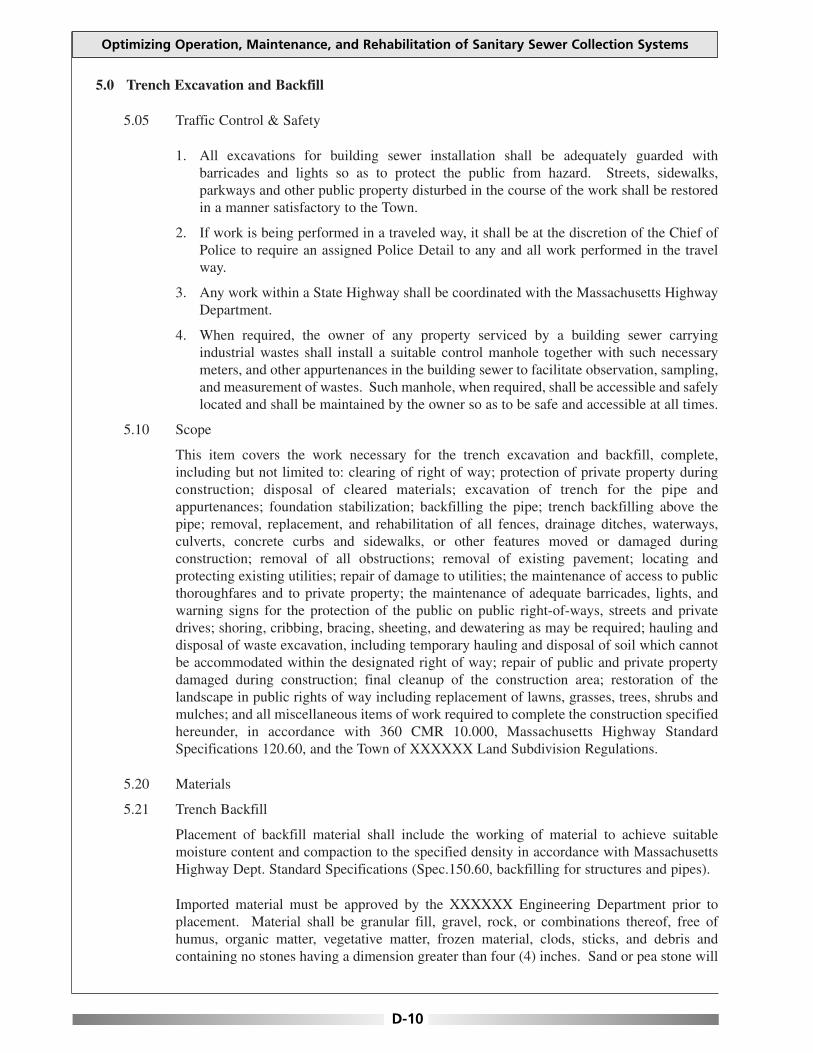
Optimizing Operation, Maintenance, and Rehabilitation of Sanitary Sewer Collection Systems
5.0 Trench Excavation and Backfill
5.05 Traffic Control & Safety
1. All excavations for building sewer installation shall be adequately guarded with barricades and lights so as to protect the public from hazard. Streets, sidewalks, parkways and other public property disturbed in the course of the work shall be restored in a manner satisfactory to the Town.
2. If work is being performed in a traveled way, it shall be at the discretion of the Chief of Police to require an assigned Police Detail to any and all work performed in the travel way.
3. Any work within a State Highway shall be coordinated with the Massachusetts Highway Department.
4. When required, the owner of any property serviced by a building sewer carrying industrial wastes shall install a suitable control manhole together with such necessary meters, and other appurtenances in the building sewer to facilitate observation, sampling, and measurement of wastes. Such manhole, when required, shall be accessible and safely located and shall be maintained by the owner so as to be safe and accessible at all times.
5.10 Scope
This item covers the work necessary for the trench excavation and backfill, complete, including but not limited to: clearing of right of way; protection of private property during construction; disposal of cleared materials; excavation of trench for the pipe and appurtenances; foundation stabilization; backfilling the pipe; trench backfilling above the pipe; removal, replacement, and rehabilitation of all fences, drainage ditches, waterways, culverts, concrete curbs and sidewalks, or other features moved or damaged during construction; removal of all obstructions; removal of existing pavement; locating and protecting existing utilities; repair of damage to utilities; the maintenance of access to public thoroughfares and to private property; the maintenance of adequate barricades, lights, and warning signs for the protection of the public on public right-of-ways, streets and private drives; shoring, cribbing, bracing, sheeting, and dewatering as may be required; hauling and disposal of waste excavation, including temporary hauling and disposal of soil which cannot be accommodated within the designated right of way; repair of public and private property damaged during construction; final cleanup of the construction area; restoration of the landscape in public rights of way including replacement of lawns, grasses, trees, shrubs and mulches; and all miscellaneous items of work required to complete the construction specified hereunder, in accordance with 360 CMR 10.000, Massachusetts Highway Standard Specifications 120.60, and the Town of XXXXXX Land Subdivision Regulations.
5.20 Materials
5.21 Trench Backfill
Placement of backfill material shall include the working of material to achieve suitable moisture content and compaction to the specified density in accordance with Massachusetts Highway Dept. Standard Specifications (Spec.150.60, backfilling for structures and pipes).
Imported material must be approved by the XXXXXX Engineering Department prior to placement. Material shall be granular fill, gravel, rock, or combinations thereof, free of humus, organic matter, vegetative matter, frozen material, clods, sticks, and debris and containing no stones having a dimension greater than four (4) inches. Sand or pea stone will
D-10

Appendix D: House Lateral Design Standards
not be an approved backfill material. No backfill shall be placed on or against structures, pipes, or any other masonry until a visual inspection has been performed by the XXXXXX Engineering Department or its authorized agent.
Unacceptable material shall be removed at the direction of the Town Engineer.
5.22 Crushed Stone
Material for pipe base shall be 3/4 inch minus crushed stone, having reasonably even gradation from coarse to fine, in accordance with the Massachusetts Highway Department Standard Specifications for Highways and Bridges specification for Aggregates and related materials M2.010 (Sect. 230.61).
5.23 Gravel for Trench Backfill
Gravel for trench backfill shall be clean pit run gravel, crushed rock or gravel having a reasonable even gradation from coarse to fine. The maximum size shall be four (4) inches.
5.24 Bituminous Concrete
Asphaltic concrete shall be hot plant mix, type I-1 material conforming to the requirements of MA Highway Section 420, entitled, “Class I Bituminous Concrete Base Course” of the Standard Specifications of the Massachusetts Highway Dept. Contractor shall replace bituminous concrete in two lifts, binder and wearing course in thickness’ equal to the existing binder but in no case less than 2.5” binder and 1.5” wearing course.
5.25 Controlled Density Fill
Controlled Density Fill (CDF) where required, shall be a mixture of Portland cement, fly ash, aggregates, water and admixtures proportioned to provide a non-segregating, self-consolidating, free-flowing and excavatable material that will result in a hardened, dense, non-settling fill. CDF is approved as an alternative to “Gravel for Trench Backfill” and as an alternative to “Crushed Gravel” and may be used at any location on the project at the option of the contractor for stabilization material, pipe base material, pipe zone material, trench backfill material and pavement base material. The use of CDF is required for backfill material associated with outside drop manholes, and any construction in paved roadways having been paved or surfaced within five (5) years, or at the discretion of the XXXXXX Public Works Superintendent.
6.0 General Construction
6.11 Clearing the Right of Way
Where clearing of the right of way is necessary, it shall be completed prior to the start of the trenching. Trees and brush shall be cut as near to the surface of the ground as practicable and piled for disposal. Contractor shall remove all organic material, grub stumps and strip loam & subsoil to granular mineral material. The Contractor shall observe all state laws relating to fire permits and local regulations relating to burning such materials. Under no conditions shall excavated materials be permitted to cover brush or trees prior to clearing and disposal. In accordance with Massachusetts Highway Dept. Standard Specifications (Sect 101).
6.12 Pavement Removal and Replacement
All bituminous and concrete pavements, regardless of the thickness, shall be saw-cut where
D-11
Optimizing Operation, Maintenance, and Rehabilitation of Sanitary Sewer Collection Systems
required prior to excavation of trenches. Width of the pavement cut shall be at least six (6) inches greater than the required width of the trench at ground surface on each side. Pavement removed during excavation shall be piled separately from the earth spoil and removed from the site and shall not be used in backfilling the trench.
After the trench has been backfilled and compacted according to the design specifications, the Contractor shall bring the trench to a smooth even grade at the proper depth below the existing surface to provide for the required depth of pavement. The Contractor shall saw-cut the existing pavement to a straight line and remove any pavement that has been damaged during work as required by the Superintendent of Public Works and or the Engineering Department.
The entire existing paved surface shall be cleaned and the sawn edges prepared with tack before resurfacing is begun. The trench shall be repaired per the specifications set forth in the Street Opening Permit issued by the XXXXXX Public Works Department.
6.13 Blasting
Blasting for excavation will be permitted only after securing approval of the XXXXXX Fire Department and only when proper precautions are taken for the protection of persons and property. Any damages caused by the blasting shall be repaired by the Contractor at his own expense. The Contractor’s methods of procedure and blasting shall conform to all applicable State laws and municipal ordinances.
6.14 Trench Width
In all cases, trench width shall be confined to dedicated right-of-way for public thoroughfares or within areas for which construction easements have been obtained, unless special arrangements have been made with the affected property owners beforehand and approved by the Engineering Department.
6.15 Grade
The bottom of the trench shall be carried to the lines and grades shown on the Plans or as established by the design Engineer, with proper allowance for pipe thickness and for proper bedding.
6.16 Shoring, Sheeting, and Boxing of Trenches
Whenever necessary to prevent caving during excavation in gravel, sandy soil, or other unstable material, the trench shall be adequately sheeted and braced. Failure to comply with proper applicable OSHA standards with regard to; sheeting, shoring, or bracing shall be cause for a Notice of Violation. All sheeting, shoring and bracing of trenches shall conform to those standard requirements.
6.17 Location of Excavated Materials
During trench excavation, the Contractor shall locate the excavated material so it will not obstruct a traveled roadway or street; and, unless otherwise approved by the Public Works Superintendent, all streets and roadways shall be kept open to at least one-way traffic, or as directed by the XXXXXX Police Department.
D-12

Appendix D: House Lateral Design Standards
6.18 Removal of Water
The Contractor shall provide and maintain ample means and devices with which to promptly remove and properly dispose of all water, including flow from existing sewer lines, entering the trench excavation during the time the trench is being prepared for the pipe laying, during the laying of the pipe, and inspection, until the backfill above the pipe has been completed accordingly.
The Contractor shall be responsible for dewatering the trench. If the Contractor wishes to dewater into the Towns drainage system, the XXXXXX Engineering Department must approve any and all means for the transfer, treatment and disposal thereof before any discharge occurs.
The Contractor shall dispose of the water and or sewage in accordance with state and local regulations. Precautions against sedimentation control must be maintained at all times.
6.19 Trench Backfill Compaction
After the Contractor has backfilled the pipe zone of the trench as required, he shall then backfill the balance of the trench, mechanically compacting each layer to 95% of maximum density in roadways and 85% to 90% in all other areas. Where fill is required, use bank-run gravel per M1.03.0 (a six-inch maximum diameter stone size).
A cash bond to be determined by the Public Works Superintendent is to be posted for trenches that do not require flowable fill (CDF). After a period of one year, or at the discretion of the Superintendent of Public Works, the Contractor must replace the pavement. After such a time the Public Works will inspect the work and determine if the bond shall be released.
Any subsequent settlement of the trench or ditch during the above referenced time frame shall be considered to be the result of improper compaction and shall be corrected at no expense to the Town by the contractor.
6.20 Excess Excavated Material
All excess excavated materials shall be hauled and properly disposed of by the Contractor. The Contractor shall make his own arrangements for the disposal of the excavated material.
6.21 Rock Excavation
Before proceeding with rock excavation, the Contractor shall have completed the common excavation to such depths that only rock excavation remains. At this time the trench shall be made available to the design Engineer and measurements will be taken to determine the amount of rock excavation remaining. Any redirection of the sewer connection to avoid ledge outcrops must be approved by the Engineering Department.
6.22 Controlled Density Fill
Controlled Density Fill (CDF) where required, shall be a mixture of Portland cement, fly ash, aggregates, water and admixtures proportioned to provide a non-segregating, self-consolidating, free-flowing and excavatable material that will result in a hardened, dense, non-settling fill.
The use of CDF is required for backfill material associated with outside drop manholes, and any construction in paved roadways having been paved or surfaced within five (5) years, or at the discretion of the XXXXXX Public Works Superintendent.
D-13

Optimizing Operation, Maintenance, and Rehabilitation of Sanitary Sewer Collection Systems
1. Placement
CDF is a heavy material and during placement will exert a high fluid pressure against any pipe, manhole, or other material it contacts. The resultant pressure will tend to cause pipe and manholes to float or shift. CDF shall be placed in such a manner as to prevent flotation or shifting of pipe and manholes. CDF shall not be placed on frozen ground or during a time when the air temperature is 38 ºF or less and falling.
No CDF shall be placed under water.
2. Curing
Contractor shall provide steel plates k-36 steel (k-56 recommended) to span trenches or otherwise prevent traffic or construction equipment coming in contact with CDF until the CDF has hardened sufficiently to prevent rutting. Contractor shall provide cold patch on all edges of steel plates used for vehicular transition in any affected area.
7.0 Sewer Pipe Installation
7.10 Scope
This item shall include the work necessary for the installation of sewer pipe and fittings of the sizes and classes indicated, including but not limited to furnishing materials, placing crushed gravel pipe base, providing bell holes in the trench bottom; laying and jointing the pipe; installing sewer tees, wyes and laterals; furnishing pipe necessary for physical test; and testing of the line. Ductile iron pipe shall be used when the sewer line is less than three (3) feet below existing finished grade.
7.20 Materials
1. PVC Sewer Pipe
Pipe used for sewers shall be PVC. The pipe shall be of the size and type indicated on the plans and shall conform to the appropriate specifications detailed below. Pipe and fittings used in Building Sewer construction shall be smooth wall inside and out, and must be either: Polyvinyl Chloride (“PVC”) and must conform to ASTM D-3034 (SDR 35; or ASTM D-1785-99 (Schedules 40 or 80)). All pipe must have a minimum tensile strength of 34.50 Mpa as defined by ASTM D-1784. SDR rating is the ratio of the outside diameter to the pipe wall thickness.
2. Ductile Iron Pipe
Ductile iron (DI) pipe must meet ASTM A-746-99 (pressure class 350) or AWWA C-151 (pressure class 350) with exterior asphaltic coating per AWWA C-151 and interior asphaltic coating meeting AWWA C-151 or polyethylene lining complying with ASTM D-1248 of nominal 40-mil thickness.
D-14
Appendix D: House Lateral Design Standards
8.0 Installation Requirements
8.10 Permit
A Permit must be issued by the Town of XXXXXX Engineering and Public Works Departments prior to the installation or repair of a Sewer.
8.20 Licensed Contractors
Only contractors licensed by the Town of XXXXXX will be permitted to construct or repair Sewers. Any Sewer installed by contractors not licensed by the Town will be rejected. A list of licensed contractors may be obtained at the XXXXXX Engineering Department. Licensed Contractors shall not sub-contract Sewer installation work to anyone other than a Town licensed contractor. Failure to comply with this provision shall lead to a Notice of Violation for the Licensed Contractor and may result in loss of such License.
8.30 Minimum Size, Fittings and Clean-outs
Building Sewers must be a minimum of six (6) inches in diameter and sized based on the anticipated flows. Building Sewers must have a wye clean-out located ten (10) feet from the buildings exterior wall.
One clean-out will be allowed in order to change direction of the Building connection. Any subsequent change in direction will require a precast manhole with rubber boots. No change in direction more than 45 degrees shall be allowed. Ninety-degree turns require installation of a precast manhole. Two forty-five (45) degree bends may be utilized with an approval from the Town Engineer. These bends will not be allowed to achieve a change in direction that results in any future loss of subsequent manhole placement, either before or after the changes in alignment.
All clean-outs must be the same diameter as the horizontal Building Sewer into which the clean-out is connected; minimum of six (6) inches.
All clean-outs must be extended to within six (6) inches of finished grade and capped.
Slope requirements within the building must conform to the latest edition of the State of Massachusetts Plumbing Code, local codes and to these standards, whichever is more stringent.
Building Sewers must be installed at a minimum of 1.00% and where possible, not to exceed 7.00%. The Town, depending on site conditions, may modify the slope requirements.
No saddle connections to the sewer will be allowed in new subdivision construction.
Sewers must not connect directly into any manhole without the prior written approval of the Town Engineer. Inside drop connections to manholes are not permitted.
Building Sewers must maintain a minimum cover (from finished grade to top of pipe) of three (3) feet. The Town will not accept Sewers installed with less than three (3) feet of cover in a right-of-way or easement, unless prior permission has been obtained by the Town Engineer.
D-15

Optimizing Operation, Maintenance, and Rehabilitation of Sanitary Sewer Collection Systems
8.40 Minimum Elevations for Gravity Connection
1. Upon exiting the building, the Sewer must maintain a minimum cover (from finished grade to top of pipe) of three (3) feet. Where an existing sewer pipe exits an existing building with less than three (3) feet of cover, the contractor shall install the connection so as to meet minimum cover requirements as soon as is practical.
2. In cases where the building sewer crosses a water main or service with less than eighteen (18) inches of vertical separation between the pipes, the Contractor shall completely encase the joints of the sewer pipe with three (3) inches of 3,000 PSI concrete using a form (not free flow). Any joint in the sewer pipe which falls within ten (10) feet measured horizontally from the centerline of the watermain or service shall be encased. This encasement must be inspected by the Engineering Department prior to backfill. Based on existing or anticipated field conditions, the Engineering Department may require additional concrete encasement.
8.50 Future Connections
Where the sewer main passes in front of a property, provision for future connection of that property shall be provided by the Contractor and recorded with the XXXXXX Engineering Department.
Building Sewers installed for future connections must be terminated at the limit of the right-of–way or easement and plugged to ensure water tightness. A standard 2”x4” with the top four feet painted green must be installed at the end of the plugged line and recorded with the XXXXXX Engineering Department.
8.60 Grease Traps
All restaurant and food service establishments, as defined in 105 CMR 590.001 or any successor regulation, shall be equipped with a grease trap which complies with the construction and maintenance specifications set forth in Title V of the State Environmental Code 310 CMR 15.05 and 360 CMR 10.000.
Installation of a grease trap shall require the installation of an inspection manhole, immediately downstream of the grease trap. This inspection manhole shall be used to confirm the serviceability of the grease trap.
Where preliminary treatment or flow-equalizing facilities are provided for any waters or wastes, they shall be maintained continuously in satisfactory and effective operation by the owner at his own expense and reported to the XXXXXX Sewer Department on an annual basis.
9.0 Workmanship
9.10 Preparation of Trench
Crushed gravel base for pipe shall be placed in the trench to a minimum depth of six (6) inches below the invert of the pipe. The base shall be a minimum of four (4) inches for service laterals. The base shall be placed and leveled to approximate flow line grade in advance of the pipe laying. Immediately following the placement of each pipe, the crushed gravel pipe base shall be placed to the centerline of the pipe and properly chinked.
D-16

Appendix D: House Lateral Design Standards
9.20 Preparation of Sewer Pipe
All pipes and fittings shall be carefully inspected before being laid and no cracked, broken or defective pipe or fittings shall be used in the work. The ends of the pipe shall be cleaned with a brush, washed and thoroughly scrubbed where necessary to remove dirt or other foreign material.
Extreme care shall be exercised to insure that the inside surfaces of the bell are smooth and free from any projections which would interfere with the assembly or water tightness of the joint.
9.30 Laying and Jointing Pipe and Fittings
Sewer pipe shall be laid in full lengths as manufactured and shall be laid on a constant grade and in a straight alignment from manhole to manhole or cleanout. Wherever possible, pipe shall not be installed with elbows or bends. A manhole shall be located at every change in grade or horizontal alignment, but no more than three hundred (300) feet apart.
The Contractor shall layout his own work and be responsible for the execution of the work to such lines and grades to comply with the specifications stated herein.
PVC pipe is flexible in nature and may be out of grade and alignment through the middle of a pipe length even though each end is on grade and in alignment as evidenced by a laser beam or grade boards. To prevent the above situation from occurring, the contractor shall check the elevation of the top of each length of PVC pipe laid at each end and at the midpoint. The midpoint elevation shall be within 0.01 foot of the average elevation of the two ends.
For a main sewer extension in a right of way, paper street, or easement, Contractor shall use the laser beam method of maintaining grade and alignment of the pipeline unless another method is approved by the Engineering Department.
9.35 Sewer Installation
1. PVC Sewer Pipe shall be installed in accordance with the manufacturers recommended installation procedures.
2. PVC Sewer Pipe shall be connected to concrete manholes by means of an approved coupling with an elastomeric gasket, an approved waterstop or flexible sleeve. Use of Portland Cement grout for connecting PVC Sewer Pipe to manholes will not be permitted, unless previously authorized by the Town Engineer. Pipe laying shall proceed upgrade with the bell ends of bell and spigot pipe pointing in the direction of flow (uphill). Each piece shall be laid true to line and grade and in such a manner as to form a closed concentric joint with the adjoining pipe in order to prevent any sudden offsets in the flowline.
a. Main Sewers The installation of sewer pipe shall commence at the lowest point along the sewer and shall proceed so that the spigot end of the section being laid is placed into the bell end of the pipe already laid. Every precaution shall be taken to prevent foreign materials from entering the pipe while it is being placed in the trench. During laying operations, no debris, tools, clothing or other materials shall be placed in the pipe. The Engineering Department shall inspect any and all piping before backfilling occurs. No de-watering of the trench shall take place into the sewer pipe or any appurtenance.
D-17

Optimizing Operation, Maintenance, and Rehabilitation of Sanitary Sewer Collection Systems
b. Service Connections The Contractor shall place service lateral Wye branches at the locations indicated on the plans or specified by the Engineering Department. Final service lateral locations may be determined in the field after consultation with the property owner. The 6-inch side outlet shall be installed at an angle of approximately 45 degrees above the horizontal. After the Wye is in position, special pipe bedding material and select backfill shall be hand-placed and chinked around the Wye to prevent any movement of the next pipe. The Contractor shall mark the Wye with a 2”x4”.
c. If installed on private property, the Wye outlet shall be plugged with a 6-inch plug and marked with a standard 2”x4” painted green. Whenever the main sewer is installed in the street right-of-way, the Contractor shall extend the service connection from the Wye branch to the property line of the property to be served, or to the point designated on the approved plan or the Town Engineer. In no case will the Contractor be required to extend the service connection on to private property without first obtaining consent by the property owner.
Unless otherwise specified on the plans or directed by the design Engineer, each service connection shall be laid in a separate private trench on a straight line and gradient from the Wye to the end of the service connection at the property line. No service connection shall be laid on a grade of less than two percent, unless otherwise authorized or shown on the approved plans.
d. Testing of Sewer Pipe & Appurtenances Prior to final operation of a sewer main extension or building sewer, the Town may require the following testing to identify sources of infiltration/inflow (I/I):
• Low pressure air test (for sewers without building sewers).
• Video camera inspection and/or smoke testing of all lines in the presence of the Engineering Department. Site inspection of the Owner’s Premises, including the interior of the building
• Manhole Vacuum Test (Adapted from ASTM C 1244 - 93 Standard Test Method for Concrete Sewer Manholes by the Negative Air Pressure (Vacuum) Test.
10.0 Vacuum Test (Negative Air Pressure)
All lift holes and pipes entering the manhole are to be plugged. A vacuum will be drawn and the vacuum drop over a specified period of time is used to determine the acceptability of the manhole (ASTM-C1244-93).
10.10 Preparation of the Manhole
All lift holes shall be plugged with an approved non-shrink grout.
All pipes entering the manhole shall be plugged, taking care to securely brace the pipes and plugs from being drawn into the manhole. The manhole shall be set to finish grade and all paving (if applicable) completed.
A failed Vacuum Test warrants the Contractor to supply the Town with an approved method of repair. This method shall be approved by the Public Works Superintendent and Town Engineer before such repair takes place.
D-18

Appendix D: House Lateral Design Standards
10.20 Procedure
a. The test head shall be placed at the inside of the top of the frame and the seal inflated in accordance with the manufacturer’s recommendations.
b. A vacuum of ten (10) inches of mercury shall be drawn, the valve on the vacuum line of the test head closed, and the vacuum pump shut off. With the valves closed, the time shall be measured for the vacuum to drop to nine (9) inches.
c. The manhole shall pass if the time for the vacuum reading to drop from ten (10) inches of mercury to nine (9) inches meets or exceeds the values indicated by the Massachusetts Water Resource Authority.
11.0 Manhole and Cleanout Construction
11.10 Scope
This item includes the work necessary for the construction of precast manholes and cleanouts, including: concrete; furnishing and placing of the concrete precast sections; eccentric cones, pipe and fittings; cast iron frames and covers; and all appurtenances, in direct relation to the residential sewerage connection.
11.20 Materials
11.21 Concrete
Concrete used in the construction of the manhole base and other structures specified shall be so proportioned and mixed as to meet a 3,000 psi compression test after 28 days.
11.22 Precast Manhole Sections
Precast concrete sections for manholes shall be minimum of 48 inches in interior diameter. Cones shall be eccentric with a wall thickness of a minimum of five (5) inches and reinforcement similar to that of manhole sections. The tops and bottoms of the cones shall be parallel. Any manhole having a depth greater than nine (9) feet shall have an extended base.
11.23 Precast Concrete Bases
Precast base sections or manhole bases shall be approved and inspected by the Engineering Department prior to installation.
11.24 Special Fittings
The wyes, tees, and bends used in the construction of the drop manholes assembly and the cleanouts shall be either PVC or ductile iron. The pipe and fittings shall conform to the specifications as set forth in these Specifications. Drop manhole assemblies shall be encased in CDF or as required by the Public Works Superintendent.
11.25 Manhole Frames and Covers
All manhole frames and covers shall be of a size and shape detailed on the plans or approved equal. The castings shall be tough, close-grained, gray iron, free from blowholes, shrinkage and cold shuts. They shall conform to ASTM A 48 - Class 30 and shall be sound, smooth, clean and free from blisters and all defects. All castings shall be planed and ground where
D-19

Optimizing Operation, Maintenance, and Rehabilitation of Sanitary Sewer Collection Systems
necessary to ensure perfectly flat and true surfaces. Covers shall be true and shall seat within the ring at all points. Manhole covers shall have a maximum of two (2) holes. With the word “SEWER”, cast upon the cover and be American made.
11.26 Manhole Steps
Steps for precast manholes shall be of steel reinforced polypropylene plastic, or approved equal. All steps shall be in conformance with ASTM C-478 and shall be aligned vertically. All steps within a manhole shall be of the same design, type and size. Mixing of unmatched steps within the same manhole is not permitted.
Steps shall be placed where there are no incoming or outgoing lines. Loose steps shall be cause for rejection of that manhole cone or section.
11.27 Manhole Blockouts / Plugged Boot
Provide manhole blockouts and or plugged boots for sewer extensions as shown on the plan or as required by the Engineering Department. The intent of the blockout is to provide a means by which future sewer lines can be connected to the manhole with a minimum of inconvenience. The method of construction shall provide a watertight blockout and shall be approved by the Town Engineer. Construct invert channels to the manhole wall at the blockout in accordance with the invert elevation directed by the design Engineer.
11.28 Manhole Tables
a. All tables in manholes within right-of-ways, paper streets, and easements shall be made of red brick.
b. Manholes on private property, at the discretion of the contractor may choose to have a piped invert. This shall utilize two 45-degree bends and a straight section no less than 24 inches in length. A concrete table shall be poured and shaped so as to provide positive drainage to the manhole invert, and a cut-out provided in the center section PVC.
11.29 Manhole Inverts
The inverts of the manholes shall be constructed in conformance with the details shown on the Plans. The manhole inverts shall provide a smooth flow-through characteristic. No sharp edges or rough sections which will tend to obstruct the flow of sewerage will be permitted. All cement mortar used in the construction of the inverts shall be trowelled smooth. The contractor may, at his option, use precast bases with prepoured and formed inverts (channels).
11.30 Drop Manholes
Outside Drop manholes shall be constructed as required or at the location shown and as detailed on the approved plans [See detail 18.20 Appendix A]. The outside drop in its entirety shall be encased in flowable fill.
12.0 Grinder Pumps and Sewage Ejectors
a. In cases where the existing sewer will not drain by gravity to the sewerage system, a pump system shall be employed. A pump system shall consist of a precast pump chamber, with a minimum storage capacity of 1,000 gallons. A 0.5 horsepower grinder style pump and a piped connection rated for pressure in excess of 150 PSI shall be utilized.
D-20

Appendix D: House Lateral Design Standards
b.Pumps must be external to the building and situated in a 1,000-gallon pre-cast tank (minimum). Any backup into the building will be the sole responsibility of the Property Owner. The Town of XXXXXX is not liable or responsible in any way for damages due to sewage backups served by grinder/ejector pumps, or the force main line itself.
The operations, maintenance, repair and replacement of the pump and appurtenances shall be the sole responsibility of the Homeowner. This also includes the force main and/or gravity Sewer from the building to its connection into the XXXXXX Sewer main or service lateral. Said owner shall be responsible for including such sewage works in the property deed.
c.Force main connections to the XXXXXX Sewer System shall be allowed only as approved by the XXXXXX Public Works Superintendent.
12.10 Force Main Connections
At no time shall a single family Sewer Force Main tie directly into any XXXXXX Sewer Main.
The force main shall connect to a sewer manhole on private property, then the connection shall flow by gravity to the existing sewer main.
If minimum cover cannot be achieved, Schedule 80 PVC, or Ductile Iron pipe shall be used. All force mains on private property shall be a minimum of 2” schedule 40 PVC, or as approved by the Town Engineer.
Inspection of pump system shall be performed by the Engineering Department. Contractor shall provide water and shall run the pump through several cycles. Connection shall be inspected for workmanship and materials, and either be passed or failed at the time of inspection.
13.0 Sewer Easements
Public Sewers
Public Sewers shall be constructed within existing public rights of way when applicable to the extent physically and legally possible. If, upon determination by the Sewer Commissioners, a public sewer must be constructed within a private way or across private property, a permanent easement of no less than twenty-five (25) feet in width, for the construction, maintenance and operation of said public sewer shall be conveyed to the Town by appropriate persons possessing an interest in such private way or property. Variances from or waivers of the provisions of this Section may be granted in the discretion of the Sewer Commissioners only upon establishment of public necessity for such variance or waiver based upon the following and in conjunction with:
1.If an individual service connection must cross someone else’s property, the owner of the property being served by the sewer must obtain a construction and maintenance easement from the owner of the property that is being crossed (see Standard Sewer Easement Agreement, Section-19). A permit will not be issued until the easement has been gained. At no point will a building sewer be permitted to tie into a manhole within an easement.
2.No more than one (1) building or residence will be permitted to connect into an existing Sewer Easement unless the prior written approval of the Public Works Superintendent has been obtained.
D-21

Optimizing Operation, Maintenance, and Rehabilitation of Sanitary Sewer Collection Systems
3.All costs for initial installation, subsequent repair, relocation, change or replacement of Building Sewers shall be at the Owner’s expense.
4.Owner shall not place or permit to be placed any trees or other deep-rooted landscaping directly over or within twelve and one-half (12.5) foot horizontal distance of the Sewer line. Any trees or landscaping placed within the easements or rights-of-ways are at risk of being damaged or removed by the Town without the obligation of replacement.
5.Owner shall not place or permit to be placed any permanent or temporary structures, mounding, lighting, fencing, signs, retaining/landscaping/entrance walls, irrigation lines, etc. directly over or within twelve and one-half (12.5) foot horizontal distance of Building Sewers or any other sewer facility. Any of the above listed items placed within easements or rights-of-ways are at risk of being damaged or removed by the Town without the obligation of replacement.
6.It shall also be the responsibility of the Owner to insure that all manhole and clean-out top of castings extend to finish grade and are not buried, sodded over, placed in concrete, or obstructed in any way.
7.The Town may periodically perform field inspections to verify compliance with the above-mentioned requirements. If a violation exists then the Owner must immediately remedy the situation.
8.Bolted and gasketted sewer manhole covers will be required at all off road locations or anywhere deemed necessary by the Public Works Superintendent.
14.0 Protection of Water Supply
1.There shall be no physical connections between a Building Sewer and the Water Supply System or appurtenances thereto which would permit the passage of any polluted water into the water supply system. Sewers shall be laid at least ten (10) feet horizontally from any existing or proposed water line. The distance shall be measured centerline to centerline. In cases where it is not practical or allowable to maintain a ten (10) foot horizontal separation, the Town may consider the installation of the sewer closer to the water line, provided that:
a.The water line is in a separate trench or on an undisturbed earth shelf located to one side of the sewer.
b.At an elevation so the bottom of the water line is at least eighteen (18) inches above the top of the sewer line.
c.Building Sewers crossing water mains shall be laid to provide a minimum vertical separation distance of eighteen (18) inches between the outside of the water main and the outside of the sewer. This shall be the case where the water main is either above or below the sewer. The crossing shall be arranged so that the sewer joints will be equidistant and as far as possible from the water line joints. Where a water line crosses under a sewer, adequate structural support shall be provided for the sewer to prevent damage to the water line. When it is impossible to obtain proper horizontal and vertical separation as stated above, the building sewer shall be designed and constructed equal to the specifications required for water pipe, and shall be pressure tested to assure water tightness prior to backfilling.
D-22

Appendix D: House Lateral Design Standards
14.10 Well Areas-Zone II
Any Sewers within one thousand (1,000) feet of a Public Water Supply or fifty (50) feet of a domestic well, shall be of watertight construction. At a minimum, schedule 40 PVC pipe with solvent weld joints is to be used.
For all parts of new sewer connections within a designated Zone II, only hard connections will be allowed. No fernco or flexible rubber connections shall be permissible, unless approved by the XXXXXX Engineering Department.
15.0 Pipe Jacking & Directional Drilling
15.10 Pipe Jacking
A specialized tunneling method for installing underground pipelines with minimal surface disruption. Primarily used for new sewer construction, it is also used for sewer replacement and relining.
15.20 Horizontal Directional Drilling
Horizontal Directional Drilling (HDD) is a trenchless method for installing any number of utilities. It is a multi-stage process consisting of site preparation, and restoration, equipment setup, and drilling a pilot bore along a predetermined path and then pulling the product back through the drilled space. Alignment of the bore is accomplished by a hydraulic jack as the drill bit head is pushed into the ground. The orientation and tracking of the head is determined by an above ground radio detection device, which picks up radio signals generated from a transmitter on the drill itself.
Contractor is responsible for selecting or designing drilling fluids for the site specific soil and groundwater conditions. Confine free flowing (escaping) slurry or drilling fluids at the ground surface during pull-back or drilling. This can be accomplished by creating sump areas or vacuum operations to prevent damage or hazardous conditions in surrounding areas.
Any proposed pipe-jacking or directional drilling must be submitted by a registered Professional Engineer in the Commonwealth of Massachusetts, and be approved by the XXXXXX Engineering Department.
15.25 Boring Path Report
Furnish a Bore Path Report to the Engineering Department within seven (7) days of the completion of each bore path. Include the following in the report:
1. Location of project including the Permit Number and when assigned.
2. Name of person collecting the data, including title, position and company name.
3. Investigation site location.
4. Identification of the detection method used.
5. Elevations and offset dimensions as required.
15.30 Vacuum Holes
In preparation of pipe-jacking activities, an as-built showing any and all existing utilities in
D-23

Optimizing Operation, Maintenance, and Rehabilitation of Sanitary Sewer Collection Systems
the area of work must be verified by the vacuum hole method. These field locations must be submitted in lieu of any proposed sewer work.
16.0 Validity
All regulations or parts of regulations in conflict herewith are hereby repealed.
The invalidity of any section, clause, sentence or provision of these regulations shall not affect the validity of any other part of these Regulations, which can be given effect without such invalid part or parts.
These Sewer Regulations shall not contravene, nor render ineffective any of the lawfully established rules and regulations of the Massachusetts Water Resources Authority.
D-24

Appendix E: EPA Region 4 MOM Checklist
APPENDIX E EPA REGION 4 MOM CHECKLIST
This appendix contains information developed by EPA Region IV for evaluating Management, Operation, and Maintenance (MOM) programs for collection systems within the region. The checklist can be used to evaluate collection system operation and maintenance programs and to highlight program areas needing improvement.
E-1

This page is intentionally blank.

Appendix E: EPA Region 4 MOM Checklist
E-3

Optimizing Operation, Maintenance, and Rehabilitation of Sanitary Sewer Collection Systems
E-4

Appendix E: EPA Region 4 MOM Checklist
E-5

Optimizing Operation, Maintenance, and Rehabilitation of Sanitary Sewer Collection Systems
E-6

Appendix E: EPA Region 4 MOM Checklist
E-7

Optimizing Operation, Maintenance, and Rehabilitation of Sanitary Sewer Collection Systems
E-8

Appendix E: EPA Region 4 MOM Checklist
E-9

This page is intentionally blank.

Appendix C: Emergency Procedures
APPENDIX F INSPECTION FORMS
This appendix contains examples of various inspection forms obtained from the Massachusetts Water Resources Authority (MWRA), the Boston Water and Sewer Commission (BWSC), and the Monroe County Department of Environmental Services (MCDES) in New York. These inspection forms can be adapted to fit specific collection system needs. They are not presented as inclusive of all situations or circumstances.
BWSC – TV Request Form F-3
BWSC – Manhole Inspection Report F-4
MWRA – Hydraulic Structure Inspection Report F-5
MWRA – Manhole Inspection Report F-6
MWRA – Roving Crew Facility Checklist (Alewife Brook Station) F-7
MCDES – Pump Station Standard Operation Inspection List F-8
MCDES – Tunnel Facility Standard Operation Inspection List F-9
MCDES – TV Inspection Sheet F-10
F-1

This page is intentionally blank.

Appendix F: Inspection Forms
F-3

Optimizing Operation, Maintenance, and Rehabilitation of Sanitary Sewer Collection Systems
F-4

Appendix F: Inspection Forms
F-5

Optimizing Operation, Maintenance, and Rehabilitation of Sanitary Sewer Collection Systems
F-6
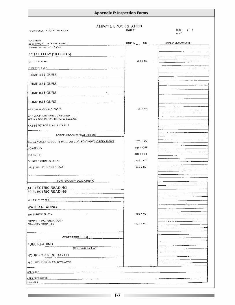
Appendix F: Inspection Forms
F-7

Optimizing Operation, Maintenance, and Rehabilitation of Sanitary Sewer Collection Systems
F-8

Appendix F: Inspection Forms
F-9

Optimizing Operation, Maintenance, and Rehabilitation of Sanitary Sewer Collection Systems
F-10

____________________________________________________________________________________
____________________________________________________________________________________
____________________________________________________________________________________
____________________________________________________________________________________
____________________________________________________________________________________
____________________________________________________________________________________
____________________________________________________________________________________
____________________________________________________________________________________
____________________________________________________________________________________
____________________________________________________________________________________
____________________________________________________________________________________
____________________________________________________________________________________
____________________________________________________________________________________
____________________________________________________________________________________
____________________________________________________________________________________
Optimizing Operation, Maintenance, and Rehabilitation of Sanitary Sewer Collection Systems
We Value Your Feedback
Please notify us if you discover mistakes or omissions in this document. Submissions can be sent electronically, mailed or faxed to:
New England Interstate Water Pollution Control Commission ATTN: Collection System Guidance
Boott Mills South 100 Foot of John Street
Lowell, MA 01852 Tel: 978/323-7929 Fax: 978/323-7919 [email protected]
Brief description of error or omission:
Suggested improvement:
General comments:
Can we contact you for additional information? If so please provide contact information:
Thank You.