optimum engine thrust deflection for high-speed cruising...
TRANSCRIPT
C.P. No. 1222
a’ Li PROCUREMENT EXECUTIVE, MINISTRY OF DEFENCE
AERONAUTICAL RESEARCH COUNClL
CURRENT PAPERS
Optimum Engine Thrust Deflection for High-Speed Cruising Aircraft
bv j. Pike
Aerodynamics Dept., R.A.E., Bedford
LONDON: HER MAJESTY’S STATIONERY OFFICE
1972
PRICE 70p NET

UDC 533.6.013.16 : 533.6.013.61 : 533.6.011.5 : 533.6.011.55 : 533.692.55
* CP.No.1222
June 1971
OPTIMUM ENGINE THRUST DEFLECTION FOR HIGH-SPEED CRUISING AIRCRAFT
by
3. Pike
SUMMARY
At high Mach numbers, an effxient cruising aircraft ~11 have a
slgnlficant fraction of its weight carried by the engines. At optimum con-
dltions, the propulsive Jet I.S xncllned to the horizontal at an angle 4,
given approxunately by
tan $I = 1.06 < - l/(2.40) >
where C w 1s a nondimensionalised aircraft weight. At thu angle, the net
thrust required 1s about 20% less than the unvectored thrust. Also, compared
with values from prev~~s analysis at constant lift-to-drag ratlo, the thrust
deflectron 1s approximately 50% larger, and the thrust required 1s typically
3% smaller.
* Replaces RAE Technical Report 71123 - ARC 33614
CONTENTS
1 INTRODUCTION 2 THE BASIC EQUATIONS
3 A SIMPLE EXAMF'LE FOR RESTRICTED CONDITIONS 4 A COMPLETE ANALYSIS FOR THE CARET WING 5 CONCLUSIONS Appendix A Definition of aerodynamic and propulsive forces Appendix B The computer program Principal symbols References Illustrations Detachable abstract cards
-
3 3 5 8
14 15 17 20 21
Figures 1-14
3
I INTRODUCTION
Consider an aircraft cruising in a homogeneous atmosphere at some fixed Mach number and height, with the lift and drag dependent on the aircraft's attitude. For constant Mach number, the drag is equal to the horizontal com- ponent of the engine thrust, and for constant height, the alrcraft weight is equal to the sum of the lift and the vertical component of engine thrust. Thus, altering the engine thrust angle will require different lift, drag and thrust forces.
Previous studies of thrust deflection' have mainly assumed constant lift- to-drag ratio, or its equivalent. Here it is assumed that the variation in the lift-to-drag ratio with lift of the caret wing is typical of that of a lifting conflguration for Mach numbers in the range where nozzle deflections are most significant (M > 5). Numerical optunlsation studies using this assumption show that optunum nozzle deflection angles are commonly 50X larger than those suggested by analysis at constant lift-to-drag ratio. Further, the engine net thrust required is typically 20% less than the net thrust without deflection and typically 3% less than that suggested by analysis at constant lift-to-drag ratio. This decrease in the required thrust reduces the rata of fuel consump- tion, and thus zncreases the aircraft range or payload. Also the reduction 1x1 engine size and weight makes the problem of engine integration easier.
Under certain restricted conditions, analytical results are obtained for the optimum nozzle deflection angle, based on Newtonian, Busemann second order and linear theory relationships. They support the results obtained by numerical methods.
2' THE BASIC EQUATIONS
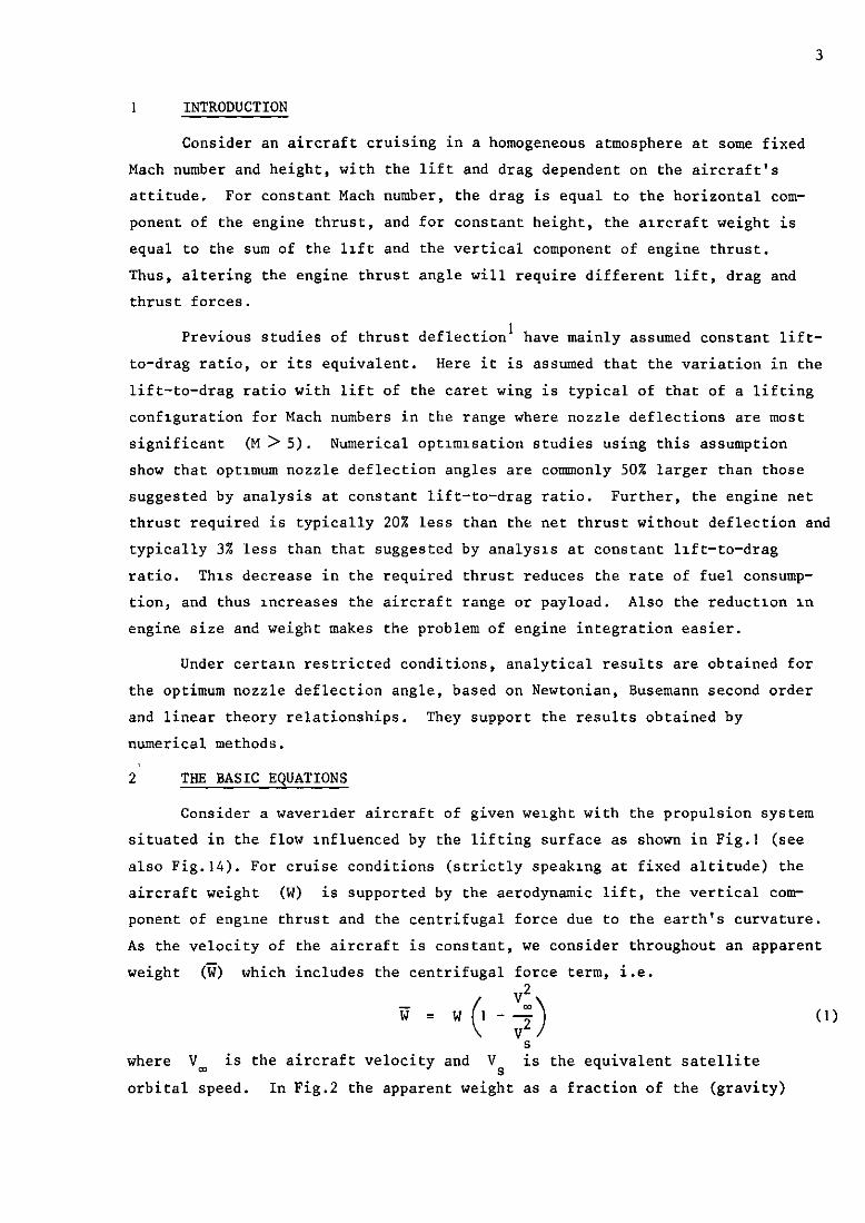
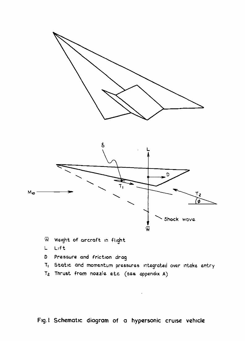
Consider a waverlder aircraft of given weight with the propulsion system situated in the flow Influenced by the lifting surface as shown in Fig.1 (see also Fig.14). For cruise conditions (strictly speaking at fixed altitude) the aircraft weight (W) is supported by the aerodynamic lift, the vertical com- ponent of englne thrust and the centrifugal force due to the earth's curvature. As the velocity of the aircraft is constant, we consider throughout an apparent weight (7) which includes the centrifugal force term, i.e.
VZ yj=Wl-2 ( ) v2
S
where V m is the aircraft velocity and Vs is the equivalent satellite orbital speed. In Fig.2 the apparent weight as a fraction of the (gravity)
4
weight is shown. Up to about Mach 8 the apparent weight differs from the actual weight by less than 10%; at higher Mach numbers a greater fraction of
the weight is carried by centrifugal effects.
Vertical resolution of the forces on the aircraft (see Fig.1) gives
L + T2 sin $ - T 1 sin 6 = ij (2)
where L is the lift, Tl 1s the reaction pressure* of the intake and T2 is the reaction pressure of the engines in the nozzle exit plane. A more detailed discusswn of these parameters is given III Appendix A. Non- dimensionalising equation (2) with respect to planform area (S) and dynamic pressure (9,) we obtain
CL + CT2 sin 4 - CT1 sin 6 = Cw =--&.
For the cruise condition assumed, Cw is a constant and the horizontal component of engine thrust exactly balances the drag, i.e.
C T2 cos $ - c T1 cos 6 = CD .
Then the following basic equations are obtained by eliminating $ and CT2 respectively from equations (3) and (4):-
2 cT2 = (C, - CL + CT1 s1n 6j2 + (CD * CT1 CO8 IQ2
(4)
(5)
tan+ = CM - CL + CT1 sin 6
CD + CT1 cos 6 (6)
To find the value of $ which minimises the engine thrust
(CT = CT2 - CT1), the right hand sides of equations (5) and (6) are expressed as functions of a single variable CC,). The engine thrust is then minimised with respect to C L by use of equation (S), and optimum values of 4 are evaluated using equation (6). It should be noted that if L/D is constant, optimum $ from equations (5) and (6) is given by $ = cot -' (L/D), as has been found previously'.
* The reaction pressure is the sum of the static and momentum pressures.
.
,
5
In the next section a preliminary investigation is undertaken for nearly-
delta planforms, by expressing CD and 6 as functions of CL using
Newtonian,Busemann second order, and linear theories. In section 4 caret wing
values are used, and a complete set of results is obtained using numerical
optimisation.
3 A SIMPLE EXAMPLE FOR RESTRICTED CONDITIONS
To express CD, 'Tl and 6 as functions of cL' it is necessary to make
assumptions concerning the aerodynamics of the aircraft. Suppose we assume
that the incidence 6 Q 1 radian and the planform is nearly delta; then the
lift coefficient 1s given approximately by
cL = A6 + B6* + O(d3) . (7)
For low supersonic Mach numbers, linear theory gives A = 418, B = 0. For
very high Mach numbers, Newtonian theory gives A = 0, B = 2. For moderate
Mach numbers we use a Busemann second order expression where A = 2/8 and
B = (y + 1)/2. We also assume that 'Tl is constant and large compared with
the drag. These assumptions, and the 6 <l restriction, are introduced for
analytical reasons. Physically they are crude assumptions requiring that the
precompressvx of the intake air by the lifting surface 1s constant, and that
enough air of high Mach number is swallowed by the intake for its reaction
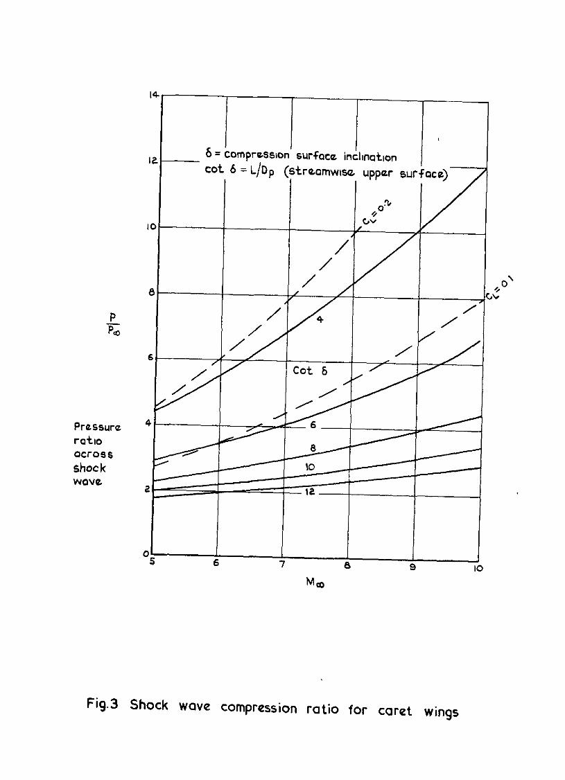
pressure to be much greater than the drag. The precompression across the shock
wave of a caret wing at various values of cot 6 and C L is shown in Fig.3.
We see that the variation of p/p m with 6 is smaller for high lift-to-drag
ratio, but that it could still be significant.
Substltutlng for CL from equation (7) in equation (5), we obtain
c;* = (Cw - A6 - B6' + CT, sin 6)' +(CDF+ (A& + Bd*) tan 6 + CT1 cos 6)* . (8)
As 'Tl 1s constant, minimum engine thrust is given by minimum C
T2' Hence
differentiating equation (8) with respect to 6 and putting dCT2/dS = 0
gives
(Cw - CL + CT1 sin 6)(CT1 cm 6 - A - 2B6)
+ (CD + CT1 cos 6)(CL se=* 6 + tan 6 (A + 2B6) - CT1 sin 6) =o . (9)
With 6 <l and CD &CTl, this reduces to
(Cw - C,)(C,, - A - 2B6) = - CTlCL . (10)
From equation (7) we have
A + 2B6 = (A2 + 4BCL) 1 (11)
hence equation (10) can be written
c" - cL cT1 cw = (A2 + 4BCL+
. (12)
Thus we have the contribution of engine thrust to the total lift porportional to the Intake reaction. Further, using linear theory values for A and B, we have that the thrust contribution is proportional ta 6. However this increase with Mach number only applies at low Mach number, for Newtonian theory suggests that the thrust contribution is given by 'Tl/& *
From equation (6)
tan $ = cw - cL 'Tl
+6 . (13)
For values of (Cw - CL) and 6 derived from linear theory, this expression becomes
For BZO, equations (ll), (12) and (13) give
C 1 tan+ = w
(A2 + 4BCL)' +
(A2 + 4BCL) A 2B --ET
A2 +6BC w A
-5' ; (15)
+4BC A2 1'
" i
C -c For wC A2 L - =<; we have
w w
Hence the Newtonian values for A and B give
tan 0 = 1.06 Jew for CL > cw/2
(that is when the aerodynamic and the Busemann second order
tan $ =
for
lift carries at least half of the weight), assumption gives
3 2c 1 - w - (y :1,, ( ) 2 y+l
cL + 8
(Y + 1)62
(16)
(17)
(18)
(that 1s except when the aerodynamic lift carries rather more than half the
weight).
Equations (14), (17) and (18) are 'patched' over their regions of most applicability in Fig.4. The poor matching along the line 8*Cw = 1 (shown dotted), IS due to the step change in the value of A between the linear theory value which includes upper surface lift, and the Busemann value which assumes it is small. The spread of the linear theory curves represents a
range of 'Tl' (a range of 0 =G CT1 Q l/M is used, and this is discussed
later). This contrasts with the Busemann and NewtonIan curves which do not
show any variation III $ with CT1. Equations (16) and (17) suggest that $ does not vary with aerodynamic drag either, and that its variation with K is linear. From Fig.4, it can be seen that linear theory is only used over a region where the optimum nozzle deflection is small. If we exclude this region
of low Mach number and lift coefficient (strictly where PC: < 0.55), we find that not only in the restricted case dealt with in this sectlon, but also for the more complete case of the following section, 0 can be represented as a simple function of C w and Mach number only.
8
4 A COMPLETE ANALYSIS FOR THE CARET WING
At high Mach numbers where the upper surface lift tends to be less important, we take the caret wing * to be typical of waverider wings*. The pressure drag and surface angle (6) : are given by3
C;
c
M* - 1 - (Y + 'DP = CL tan 6 =
1)CLM2/4 2 - CL 1 + (y + l)CLM2/4 3
' (19)
For 3 <M < 6 and CL < 0.2 the viscous drag of an inclined flat plate can be represented approximately by3
C DF = 'DFO + 'DFICL (20)
where 'DFO and C DFl are constants. At hypersonic Mach numbers it has been shown4 that friction drag varies as l/M;, where M 1 is the Mach number at the edge of the boundary layer. For the caret wing from oblique shock wave relatronships, we have
1 7' Ml
(7-l)
where i = 1 - CL 1 + M*(v - 1 + v*C,)/4
1 + M*vC,/Z
For CL cO.2, K is near unity. Hence the relationship of equation (20) also applies approximately for hypersonic Mach numbers. Equation (20) is used here as a first approximation to the variation of friction drag with lift coeffxient. For lifting configurations CDFO is the friction drag at zero lift, and CDFl is a correction factor to allow for the higher friction drag at Incidence.
From equations (19) and (20) the total drag CD (i.e. 'DP + 'DF) can be expressed as a function of CL. To obtain CT1 as a function of ' CL It is assumed that the mass of air captured by the intake is constant, that is, the area (Ap) of the free stream tube of air which will be captured by the intake is constant. Thus
* The caret wing has a delta planform,pronounced anhedral and supports a plane oblique shock wave at design incidence and M,.
.
,
T1 2A V cT1
s-s P,"_"lAp qc2 %2
= +g m
where "1 is the velocity just upstream of the intake.
Evaluating "l/V_ from caret wing conditions gives
2A cT1 = +
( l-CL
4 + YCLM'
4 + (y + 1)CLM'
Hence from equations (5). (6), (191, (20) and (22), CT expressed as functions of cL' M, Cw and *p/S, i.e.
and tan 4 may be
CT = CT2 -c T1 = w - CL + 4 + yCLM2
L 4 + (y + l)CLM'
(22)
1 2
CO6 6
[
2A
+ 'DFO + CDFICL + CL tan 6 + -$ 1 - c
- 'Tl (23)
A C - C- + 2 sin w L 62 l-CL
(
4 + yCLM2
4 + (y + ) tan $ =
l)CLM2 (
A 'DFO+ 'DFl L c +CLtan6+2cos6~ l-CL
4 + yCLM2
4 + (y + l)CLM2
cL 4M2 - 4 - (y + l)CLM2 ' where tan6 = 2 - CL 4 + (y + l)CLM2
:24)
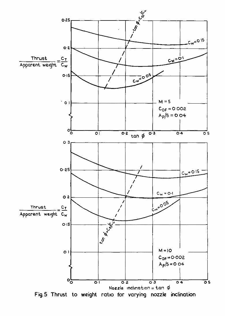
For given cruise conditions, CT and tan 4 can be calculated for any CL. In Fig.5, the variation of CT/C" (i.e. thrust/apparent weight) with tan $ is shown for Cw = 0.05, 0.1 and 0.15, CDF = 0.002, Ap/S = 0.04 and Mach numbers of 5 and 10. Typically, for a wing loading of 75 lb/sq ft and a temperature of 800 K at 5 ft behind the leading edge at M = 5, the cruxsing height is 95000 ft 5 and C " = 0.16, similarly at M = 10, 1200 K and 130 000 ft, c, is also equal to 0.16 so that values of Cw III the range 0 to 0.2 are appropriate. It should be noted that with thrust deflection, some of the wing loading quoted above is carried by the engines and the lift loading
10
will then be different from the wing loading. The weight per unit area is
probably more significant for structural use, while the lift Per unit area is
important for wing heating and boundary layer development. Thus it may be
important to distinguish between them when thrust deflection is used.
In Fig.5 for the values of Cw indicated, we see that inclining the
nozzle can reduce the thrust required by up to 20%. The deflections predicted
if lift-to-drag ratio is assumed to be constant are shown by the dotted line.
These considerably under-estimate the deflection angle for minimum thrust, and
require that the thrust be about 3% greater than the minlmum shown.
The thrust-to-weight ratio obtaned in Fig.5, falls with decreasing
weight coefficient, suggesting that efficient vehxles may need low wing load-
ings . Note that small changes in $ from the values for minimum thrust cause
Insignificant changes in the required thrust.
Minimum values of CT, with the associated $ and CL values, have
been obtained numerically from equations (23) and (24), with a maximum allowed
error in cL of 0.2% of cw. The details of the method are given in
Appendix B.
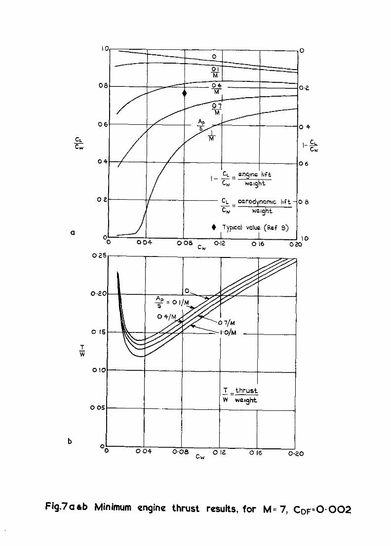
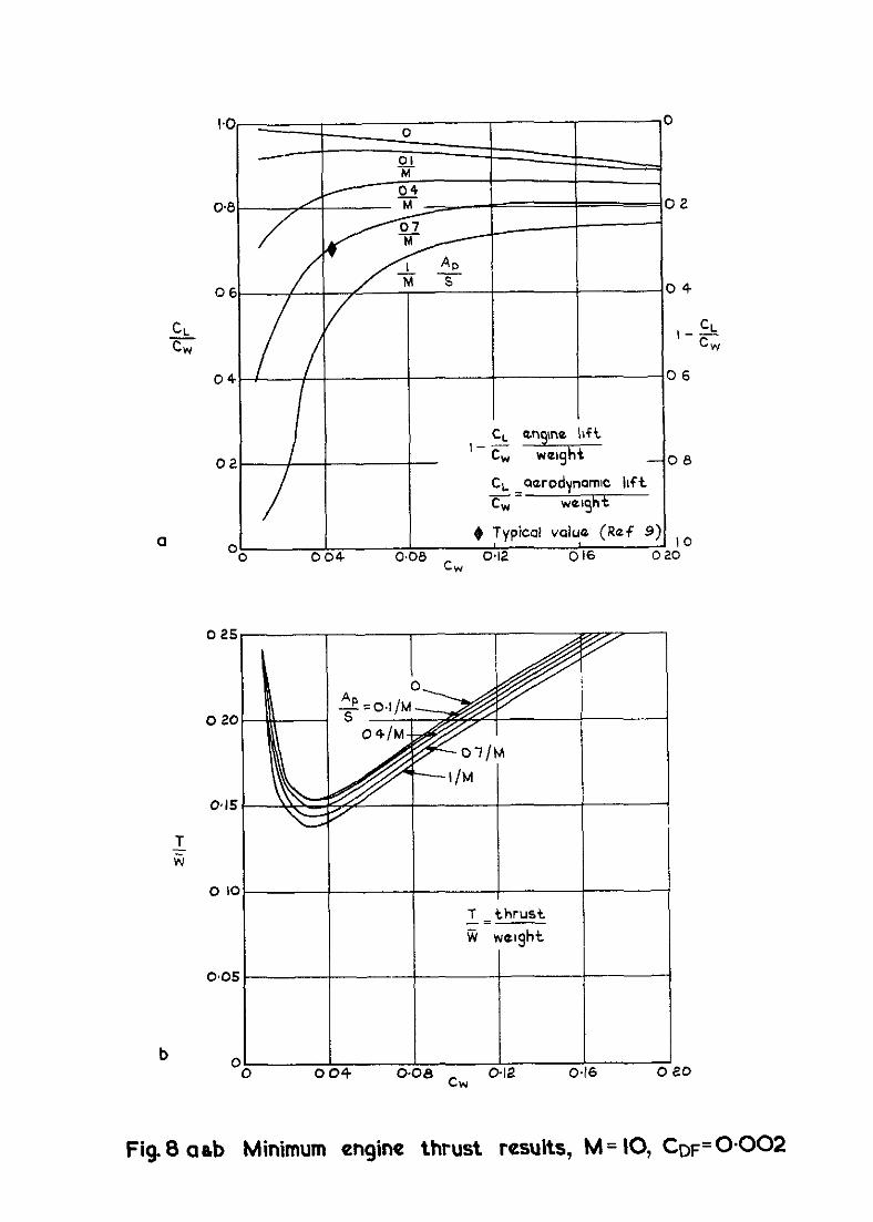
The results obtalned with free stream Mach numbers of 5, 7 and 10 and
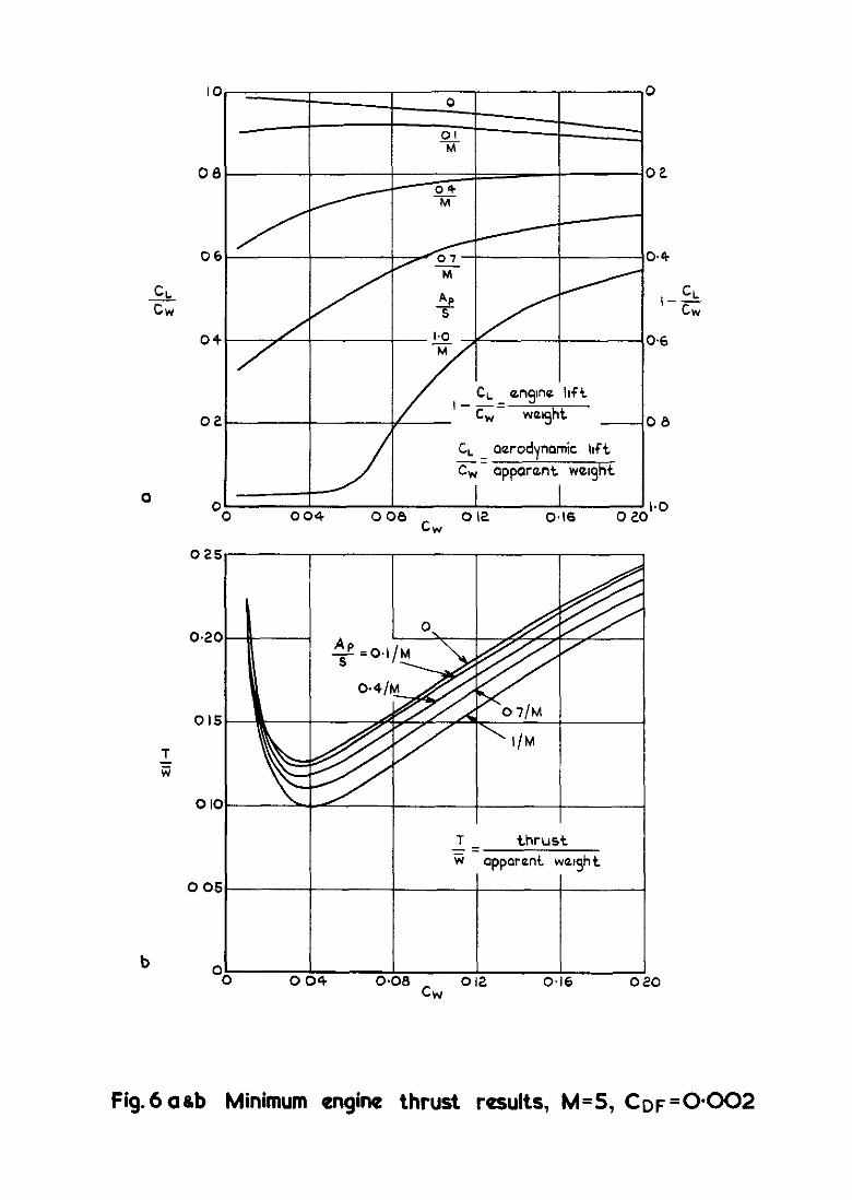
several values of CDF are presented in Figs.6 to 11. Figs.6 to 8 show the
effects of Mach number changing with a constant friction drag (i.e. CDF = 0.002).
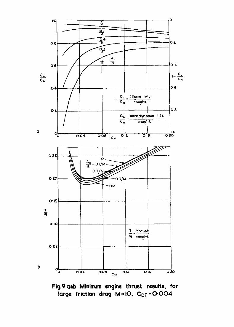
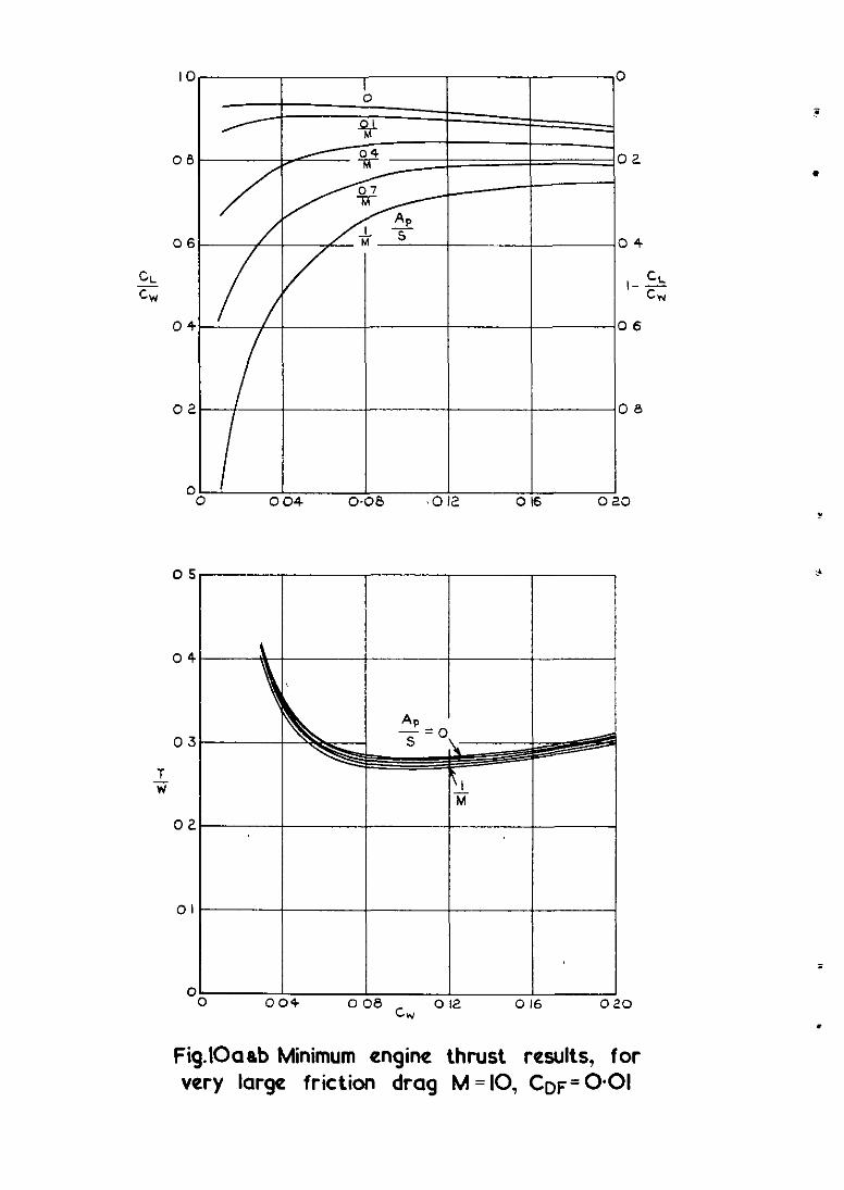
Figs.8 to 10 show the effects of increase in friction drag for a constant Mach
number (1.e. M = lo), and Fig.11 shows the results for a friction drag which
varies with lift coefficient (i.e. CDF = 0.002 (I + 10CL) from equation (20)
and Ref.3 for M = 10 and y = 1.4).
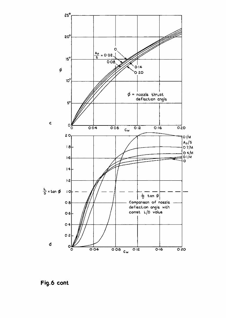
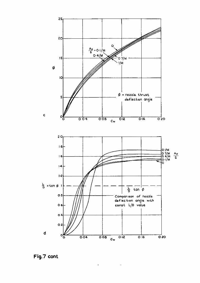
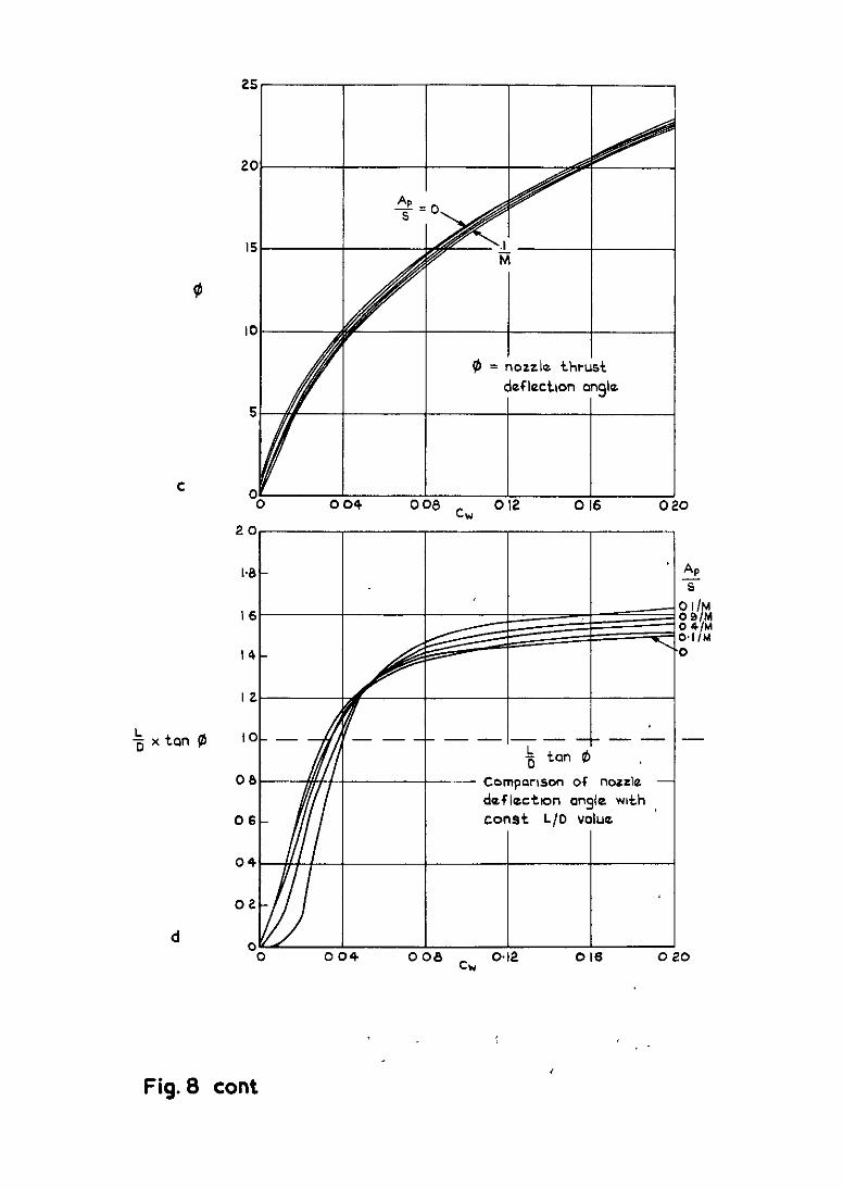
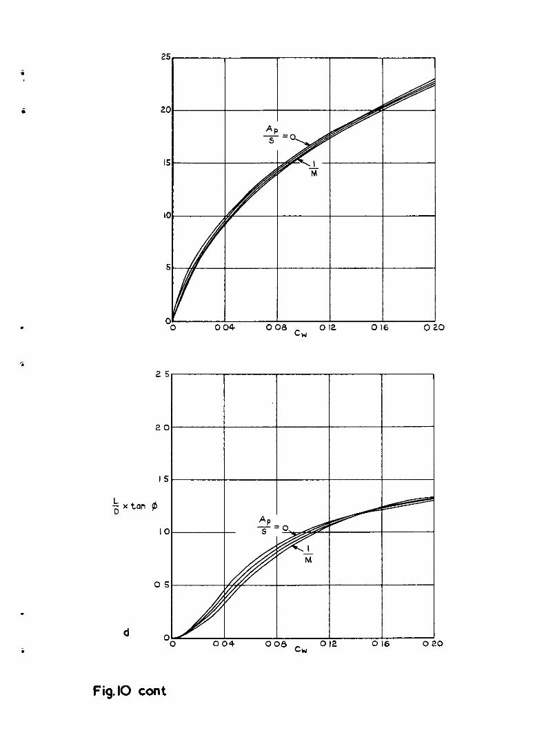
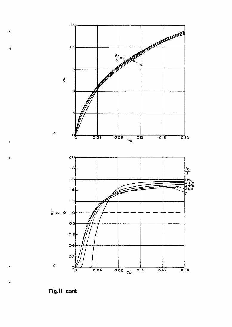
Figs.6 to 11 each show four plots labelled (a) to (d), which have Cw as
abscissa and, as ordinates, the ratio of aerodynamic lift to the apparent
"eqht (CL/Cw) , thrust to apparent weight (T/i), thrust deflection angle
($), and the ratlo of thrust deflection to that for constant lift-toA.rag ratio
condrtlons ((L/D) tan $). The five curves on each plot represent five values
of the free stream capture area of the intake (i.e. Ap/S = 0, 0.1/M, 0.4/M,
0.7/M and l/M). Note that in some cases the curves for 0 and 0.1/M are SO
close as to be indistlnguishable and only four curves are plotted. At the
largest value of the intake airflow (i.e. Ap/S = l/M), a major portion of the
air affected by the lifting compression surface is swallowed by the intake.
It should be noted that as engine efficiency must be expected to be strongly
dependent on Ap/S, ComParlson between the five curves should be made with
caution.
11
.
A wide range of C w and Ap/S (i.e. 0 =G C" 4 0.2, 0 < Ap/S < l/M) is
shown on each of the plots. Typical practical values for these parameters can
be obtalned from design studies of hypersonic transports. For example, a
design study for a Mach 7 kerosene-burning transpor@ylelded a configuratlon
which at the start of Its cruise flight at 100 000 ft had Ap/S Q 0.04,
Cw 'or 0.07 and CD Q 0.009. Most of the drag "as lift-dependent drag, the zero
lift drag coefficient (CDF) being about 0.002. In Ref.7 it is suggested that
Ap/S varies approximately as 1/M2, and that at Mach 10 it has a value of
about 0.06. Two typical values from the results of Ref.9 are shown in
Figs.7 and 8 by the 'diamond' shaped symbols. These values are for confzgurations
with optunised 3 shock wave intakes, a maximum temperature in the engine of
8 tunes free stream temperature and no thrust deflection. We see that for
these examples Ap/S Q 0.07, and C" = 0.045 at M = 10 and 0.08 at
M = 7. Thus, in general, the regions of most practical interest probably occur
at rather less than the median values of the parameters shown.
Of the plots shown in Figs.6 to 11, plots (a) show the proportions of
weight carried by the pressure under the wing (1.e. CL/C") and by the engine
(i.e. 1 - CL/C"). When Ap/S = 0.1/M, the vertical component of engIna thrust
is about 8-10% of the weight. As the amount of a~ used by the engines
increases, so does the proportion of weight carried by the engine thrust, as
"as suggested by the example of section 3. Linear theory further suggests that
the fraction of weight whxh ought to be carried by the engine thrust
increases with Mach number. However, Flgs.6a, 7a and 8a show a slight tendency
for (1 - CL/C") to fall with Mach number, a result closer to that suggested
by NewtonIan theory.
CLjC" also represents the ratio of the lift loading to the wing loading.
Thus when Ap/S = 0.1/M the lift loading is only about 90% of the wing load-
ing and the aerodynamic heating and friction drag "111 be less than with the
unvectored thrust conflguration. Consider an example based on Fig.11, where
C DF = 0.002 (1 + 10CL). If CL = 0.05 and Ap/S = 0.4/M, then
'DF = 0.003 and CL/C" = 0.8 from Fig.lla. Hence C" = 0.0625 and CDF for
the unvectored thrust conflguration would be 0.00325, an increase of about 8%
in friction drag. The disease XI thrust required to overcome this extra
drag would of course be in addition to that already demonstrated for the
unvectored thrust.
12
For Ap/S = l/M and small values of Cw, nearly all the weight is
carried by the engines and the aerodynamic lift can be neglected. Equations (5)
and (6) then become simply
and
2 'T2
2 = c2 + (CT1 +c DF)
2
tan $ = C”/(CT1 + CDF) . (26)
This result is similar to that at constant lift-to-drag ratio, where the lift
is replaced by the weight and the drag Includes the intake reaction. We note,
however, that for most of the range of interest both the aerodynamic and the
engine lift are important.
The aim of deflecting the thrust T2 1s to reduce the required net
thrust T (i.e. T2 - Tl). Plots (b) show minimum values of the ratio of
thrust to apparent weight (i.e. Tlij or (CT2 - CTl)/C") for cw up to 0.2.
It can be seen that T/i is smallest for C, values of about 0.04 or 0.05.
The mlnimum value of T/i increases with Mach number and CDF, from about 0.1
when M = 5 and C DF = 0.002, to about 0.2 when M = 10 and CDF = 0.004.
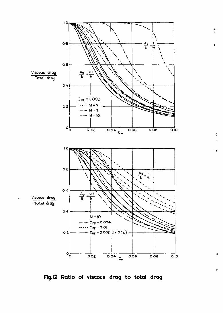
Analysis relating to lifting configuratlons without a propulsion system,
suggests that, for high aerodynamic efficiency the friction drag should be
slightly less than the pressure drag 3,g . It is interesting to consider the
ratio of friction drag to total drag for the conflgurations obtained here.
In Fig.12, where this is plotted, there is considerable variation XI the ratlo.
However when the ratio of friction to total drag is 0.4 (giving good aero-
dynamic efficiency), we find significantly, that the thrust-to-weight ratio
in plots (b) 1s near its minimum value, with the exception of those cases where
most of the weight is supported by the engines.
Unless low wing loadings and high surface temperatures' are acceptable
values of c w much larger than 0.05 are required. Thus a compromise "111
exist between the values of C w for minimum thrust suggested here and
structural requirements. As the thrust penalty for moving away from the minimum
is at first small, practical values of C w must be expected to be greater than
the value for minimum T/G. For the hypersonic transport of Ref.6, the value
of c was 0.07. w For values of C
linearly with Cw, such that with :DF
above about 0.06, T/W increases nearly
= 0.002 for the range of M and Cw a 1% increase ID weight requires a 2% increase in thrust. This penalty for weight
.
i
13
.
increase, may demand that, for a cruising aircraft, the value of C is not too w remote from the minimum thrust value. It 1s clear that improvements in materials
or structural design which llghten the airframe, will produce significant
increases in the efficiency of hypersonic cruising aircraft.
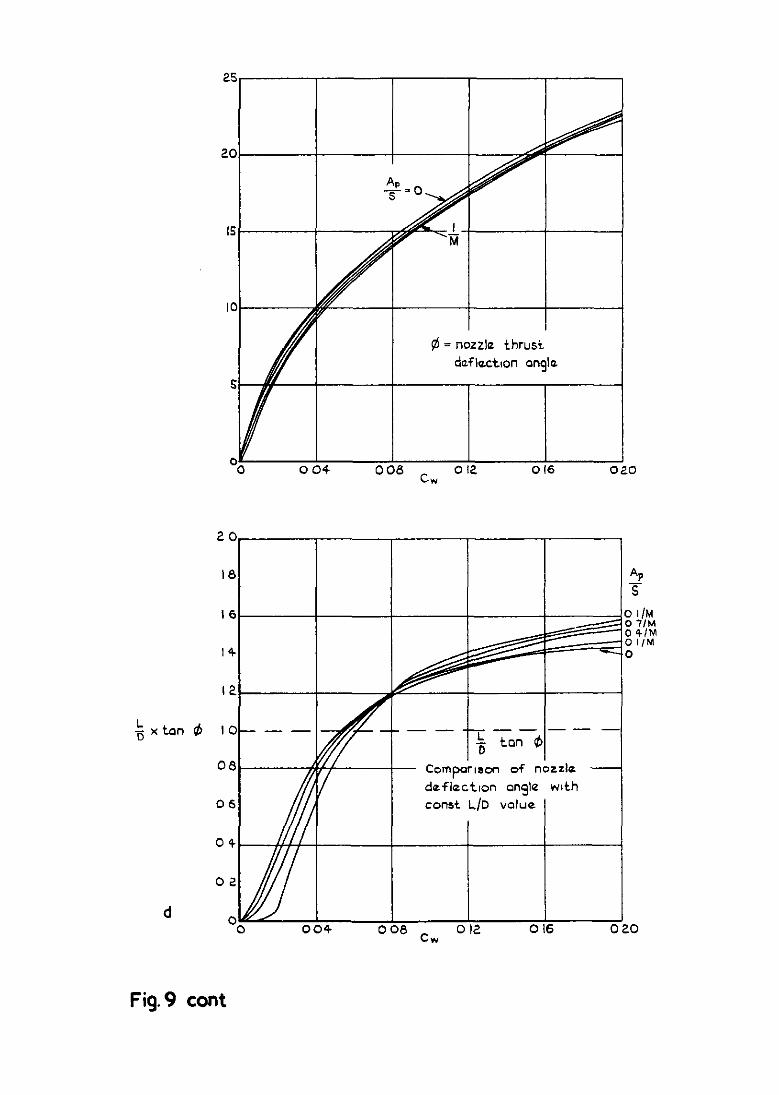
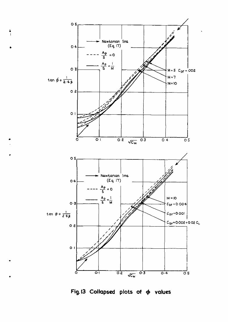
The thrust deflection angle is shown plotted against Cw in plots (c).
Equations (17) and (18) of section 3 suggest a simple variation of $ with
c" and Mach number. In Flg.13, the results shown in Figs.&llc are plotted
according to a relationship indicated in equation (18); that is for y = 1.4
they are plotted as tan + + 112.48 against K. We see that for a wide
range of engine mass flow, friction drag and Mach number, all the curves
collapse closely on to the line obtained from Newtonian theory (equation (17)),
and indicated in Fig.13 by the 'arrows'. Hence for M > 5 and Cw > 0.01, $
1s given by the simple relationship
tan 0 = 1.06 < - 112.48 . (27)
Thus the optimum thrust deflection angle may be obtalned directly from the
aircraft weight, plan area and cruise conditions.
The aircraft weight varies throughout the cruise phase of the flight as
the fuel is used. Equation (27) thus suggests that for fixed height the thrust
inclination should decrease during the flight. However If the cruise height
Increases during the flight such that p, decreases as the weight, Cw and
thus $ will be constant.
Although the present analysis 1s based on aircraft weight, the angle
which would have been suggested by assuming constant lift-to-drag ratio (i.e.
6 = cot -' (L/D)) can be evaluated for the particular conflgurations obtalned.
In plots (d), the ratlo of the tangents of the two angles (i.e. (L/D) tan 9)
is shown. For the range of Cw (or CL) of practical interest, we see that
@ is substantially larger than cot-l (L/D). Thus at a given altitude,
adopting the angle based on constant lift-to-drag ratio would result not only
inChigher thrust, but also larger lift loading, giving greater aerodynamic
heating and friction drag.
It should be noted that although for simplicity the results are derived
for constant height and speed, they apply also for constant rates of change of
speed and a climb angle 8, if the weight coefficient CW 1s replaced by
cw cos e and CDFO is replaced by (CDFO + C sin 0 + (CwG/g)) throughout. w
When the engine thrust is deflected so as to minimise net thrust, it is found for M Z 5, that the thrust may support a significant proportion of the .
aircraft weight. For example, when the engine air free stream tube is aboutO.l/M of the plan area, the thrust supports about 10% of the weight. This percent- age increases rapidly with increasing engine free stream capture area, until for certain conditions nearly all the lift is provided by the engines.
The minimum thrust to weight ratio varies markedly with weight coefficient
(i-&S). Its smallest value occurs at a weight coefficient of 0.04, which is thought to be rather low for practical purposes. The value of the thrust-to-
weight ratio is then about 0.1 for M = 5 and C DF = 0.002, and increases with Mach number and friction drag to about 0.2 when M = 10 and C DF = 0.004. These values occur near the conditions of maximum lift-to-drag ratio of the lifting surface.
In practice, there is a tendency for structural requirements to require weight coefficients larger than the values for minimum thrust-to-weight ratio. At these higher values of weight coefficient, the minimum thrust-to-weight ratio uxreases almost linearly with weight coefficient, such that typically for
'DF = 0.002 a 1% increase in weight requires a 2% increase In thrust. Hence, for a cruising alrcraft, there 1s a considerable extra incentive for keeping the structure weight as low as possible.
It is found that the thrust deflection for minimum thrust is almost independent of friction drag and engine free stream capture area. A simple but accurate expression for the optimum inclination to the horizontal of the cruising thrust is given by
tan $ e 1.06 < - 112.46 .
The adoption of this angle for a cruising aircraft results in a thrust
requirement typically 20% less than the unvectored thrust and 3% less than the value from analysis at constant lift-to-drag ratio. A further advantage of thrust deflection is that, for a given weight coefficient, the aerodynamic loading of the lifting surface 1s reduced, thus reducing the aerodynamic heat- ing and skin friction.

15
.
f
Appendix A
DEFINITION OF AERODYNAMIC AND PROPULSIVE FORCES
At hypersonic Mach numbers the division of the forces on an aircraft into
'propulsive' and 'aerodynamic' forces is, to some extent, arbitrary. For
example, forces associated with the intake pre-entry flow, the flow over the
engine cowl and the influence of the engine cowl on the wing, do not
conveniently fit into either category. It may be argued that analysis which
requires that all these forces necessarily be grouped as aerodynamic or pro-
pulsive will be artificial, and worthwhile results can best be obtained from
project analysis for particular conflguratlons. However from a limlted number
of project results, it 1s difficult to establish general relationships between
the parameters involved. General relationships, if they exist, are not only
more likely to be found from analysis admitting a range of conflgurations but
are often largely independent of the detailed assumptions necessary to define
the problem. For example, it is found ln this Report that the results based on
the crude assumptions of section 3, predict remarkably closely the main results
based on the more detalled assumptions of section 4.
The relationships of particular Interest in the Report, are those between
the engine thrust deflectlon and the aerodynamic parameters of the aircraft.
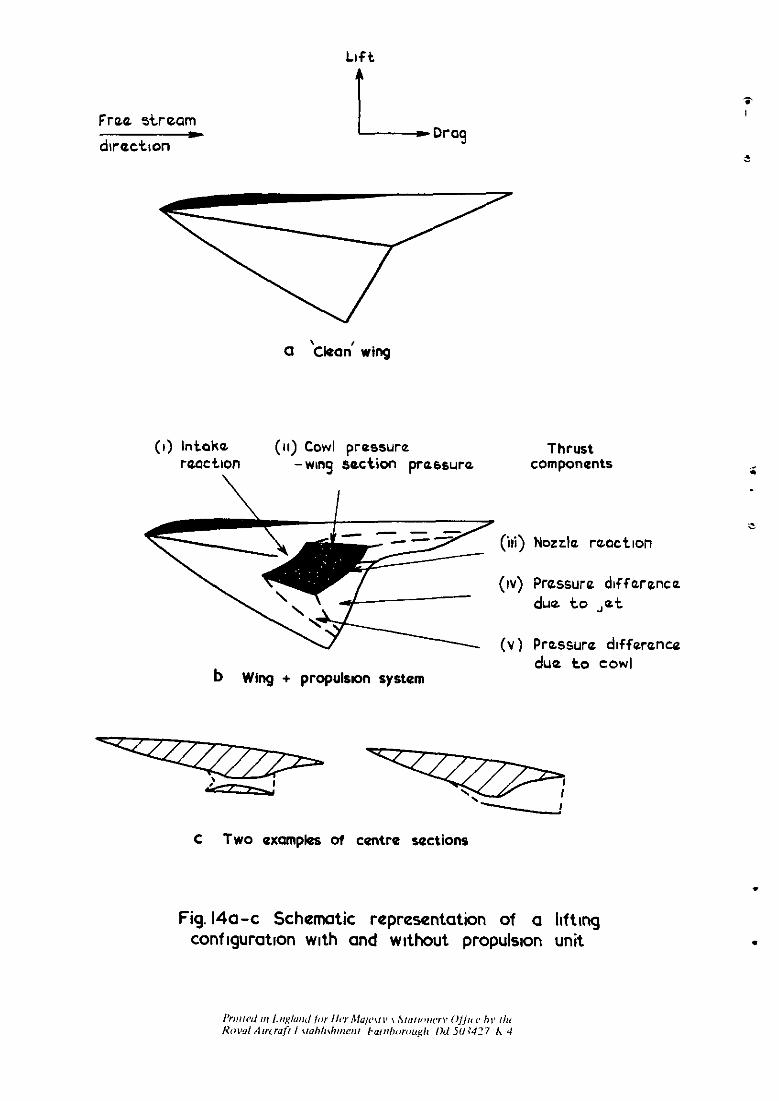
In Fig.llra, an aircraft configuration without a propulsion system 1s shown.
The approximate aerodynamic force coefficients of such wings have been
postulated 298 for a wide range of hypersonic Mach numbers and lift coefficients.
Hence these wings provide a convenient aerodynamic basis for analysx. In
Flg.14b a propulsion system has been added and five components included here
in the propulsive force are listed.
The reaction pressure (i.e. the static and momentum pressures) Integrated
over the intake (see (i) of Fig.14b) is denoted by Tl in the Report. If the
flow approaching the intake 1s not uniform, Tl will differ slightly according
to the surface of integration used. For intakes which start their compression
with a shock wave, this surface is most convemently taken just upstream of
the shock wave. If the intake compression LS initially Isentropic,
distinguishing the lifting surface compression from the intake compression may
be more difficult. A convenient surface to define uniquely the intake reaction
in this case, is the upstream Mach surface from the cowl lip. The effect of
small changes in the wing surface downstream of the intersection of this Mach
surface with the wing are swallowed by the intake and will not affect the
16 Appendix A
lifting flow. Examples of these surfaces are shown in Fig.14c. In the left hand section the dashed line at the intake shows a typical surface' just upstream of the shock wave. The right hand section shows a typical surface for an isentropic compression.
The reaction pressure at the nozzle and any interference effects of the let or cowl on the flow are included with the nozzle thrust term (T2). For example, expansion of the jet downstream of the cowl may be used to provide considerable additional force on an appropriately reshaped wing. This force (minus that which would have been obtained from the same region of the clean configuration), is included in the thrust term T 2 (see (iv) of Fig.14). The engine cowl can have pressure forces on it differing from those of the clean wing, and can also influence the pressure over a region of the wing (see (ii) and (v) of Fig.14). These forces are also included in the thrust term T2.
Friction forces differ for the two wings due to different surface
curvatures and wetted areas, but as these forces are dealt with rather crudely by assuming an overall skin friction drag, this is taken to relate to the drag of the configuration with its propulsion system.

17
Appendix B
THE COMPUTER PROGRAM
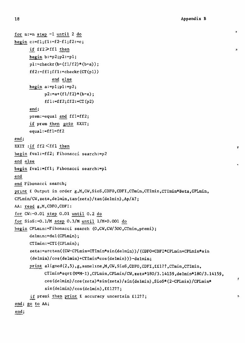
The results of section 4 were obtained using the computer program shown
below. It is written in Algol 60, with programming restrictions and input- output conventions suitable for an Elliott 503 digital computer.
J. Pike, HSST, RAB Bedford, Sept. 67 Optimum Nozzle deflectlon for Waveriders; begin real g,M,SioS,CW,CDFO,CDFI,CPLmin,CTmin,delmin,CTImin,zeta; Boolean preml; switch ss:=AA; real procedure CTI(P);value P; real P; -~ begin CTI:=2~sqrt(l-P*(l+g/4*M*M*P)/(l+(g+l)/4*M*M*P))*SloS; edd CTI; - real procedure del(P); value P; real P; -- begin del:=arctan(P/(2-P)*sqrt((M*M-l-(g+l)/4*M*M*P)/(l+(g+l)/4*M*M*P))); end del; - real procedure CT(P); value P; real P; -- begin CT:=sqrt((CW-P+CTI(P)*sin(del(P)))42+(CDFO+CDFI*P+P*sin(del(P))/cos(del(P))t
CTI(P)*cos(del(P)))t2)-CTI(P); end CT; - real procedure Fibonacci search (a,b,eps,fval,prem); value a,b,eps; real a,b,eps,fval; Boolean prem; begin real e,ffl,ff2,pl,p2; integer n,fl,f2,c; Boolean equal; switch sss:=EXIT;
equal:=false; n:=l;fl:=2;f2:=3; e:=(b-a)/eps; for c:=fl while fZ<e do - begin Ix=n+l;fl:=f2;f2Z+f2
end; - p2:=(fl/f2)*(b-a)+a;pl:=a+b-p2; ffl:=CT(pl);ff2:=CT(p2);
18 Appendix B
for n:=n step -1 until 2 & - begin c:=fl;fl:=f2-fl;f2:=c;
if ff2>ffl then - begin b:=p2;p2:=pl; pl:=checkr(b-(fl/f2)*(b-a)); ff2:=ffl;ffl:=checkr(CT(pl))
end else -- begin a:=pl;pl:=p2;
p2:=a+(fl/f2)*(b-a); ffl:=ff2;ff2:=CT(p2)
*; prem:=equal and ffl=ff2; - if prem then gOto EXIT; - - equal:=ffl=ff2
&; EXIT :if ff2<ffl then - begin fval:=ff2; Fibonacci search:=p2 end else -- begin fval:=ffl; Flbonacci search:=pl end - end Fibonacci search; - print E Output in order g,M,CW,SioS,CDFO,CDFI,CTmin,CTImin,CTImin*Beta,CPLmin,
CPLmin/CW,zeta,delmin,tan(zeta)/tan(delmin),Ap/A?; AA: read g,M,CDFO,CDFI: for cw:-0.01 step 0.01 eo.2 & - for SioS:=O.l/M step 0.3/M until l/M+O.OOl & - begin CPLmln:=Fibonacci search (O,CW,CW/500,CTmin,premi);
delmln:=del(CPLmin); CTImin:=CTI(CPLmin); zeta:=arctan((CW-CPLmin+CTImin*sin(delmin))/(CDFO+CDFI*CPLmin+CPLmin*sin (delmin)/cos(delmin)+CTImin*cos(delmin)))-del~in;
& aligned(2,5),g,samel~ne,M,CW,SioS,CDFO,CDFI,ffl??,CTmin,CTImin, CTImin*sqrt(M*M-1),CPLmin,CPLmin/CW,zeta*180/3.14159,delmin*180/3.14159, cos(delmin)/cos(zeta)*sin(zeta)/sin(delmin),SioS*(2-CPLmin)/CPLmin* sin(delmin)/cos(delmin),ffl2??;
if premi then print f accuracy uncertain fl2??; + - end; go to AA; - -- &;
Appendix B 19 123
.
i
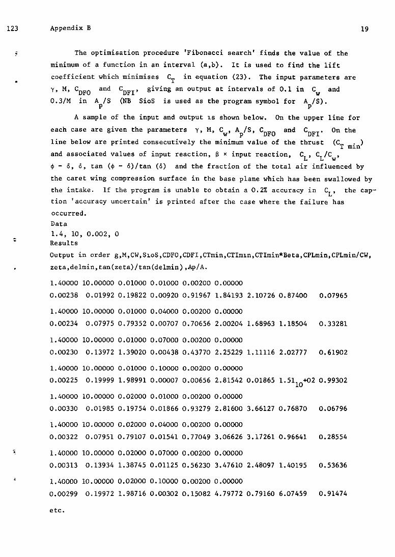
The optimisation procedure 'Fibonacci search' finds the value of the minimum of a function in an interval (a,b). It is used to find the lift coefficient which minimises C T in equation (23). The input parameters are
Y. M, CDFO and C DFI' giving an output at intervals of 0.1 in C, and 0.3/M in Ap/S (NB SioS is used as the program symbol for Ap/S).
A sample of the input and output 1s shown below. On the upper line for
each case are given the parameters y, M, Cw, Ap/S, CDFO and CDFI. On the line below are printed consecutively the minimum value of the thrust (CT min) and associated values of input reaction, 8 x input reaction, CL, CL/C”, 4 - 6. 6, tan (I$ - b)/tan (6) and the fraction of the total air influenced by the caret wing compression surface in the base plane which has been swallowed by the intake. If the program is unable to obtain a 0.24 accuracy in CL, the cap- tion 'accuracy uncertain' is printed after the case where the failure has occurred. Data 1.4, 10, 0.002, 0 Results Output in order g,M,CW,S~oS,CDFO,CDFI,CTmin,CTIm~n,CTImin*Beta,CPL~in,CPLmin/CW, zeta,delmin,tan(zeta)/tan(delmin),Ap/A.
1.40000 10.00000 0.01000 0.01000 0.00200 0.00000 0.00238 0.01992 0.19822 0.00920 0.91967 1.84193 2.10726 0.87400 0.07965
1.40000 10.00000 0.01000 0.04000 0.00200 0.00000 0.00234 0.07975 0.79352 0.00707 0.70656 2.00204 1.68963 1.18504 0.33281
1.40000 10.00000 0.01000 0.07000 0.00200 0.00000
0.00230 0.13972 1.39020 0.00438 0.43770 2.25229 1.11116 2.02777 0.61902
1.40000 10.00000 0.01000 0.10000 0.00200 0.00000 0.00225 0.19999 1.98991 0.00007 0.00656 2.81542 0.01865 1.5110+02 0.99302
1.40000 10.00000 0.02000 0.01000 0.00200 0.00000 0.00330 0.01985 0.19754 0.01866 0.93279 2.81600 3.66127 0.76870 0.06796
1.40000 10.00000 0.02000 0.04000 0.00200 0.00000 0.00322 0.07951 0.79107 0.01541 0.77049 3.06626 3.17261 0.96641 0.28554
1.40000 10.00000 0.02000 0.07000 0.00200 0.00000 0.00313 0.13934 1.38745 0.01125 0.56230 3.47610 2.48097 1.40195 0.53636
1.40000 10.00000 0.02000 0.10000 0.00200 0.00000
0.00299 0.19972 1.98716 0.00302 0.15082 4.79772 0.79160 6.07459 0.91474
etc.
20
cD C DF
'DP
cL
cT1
'T2
cT
cw D L S
T1
T2
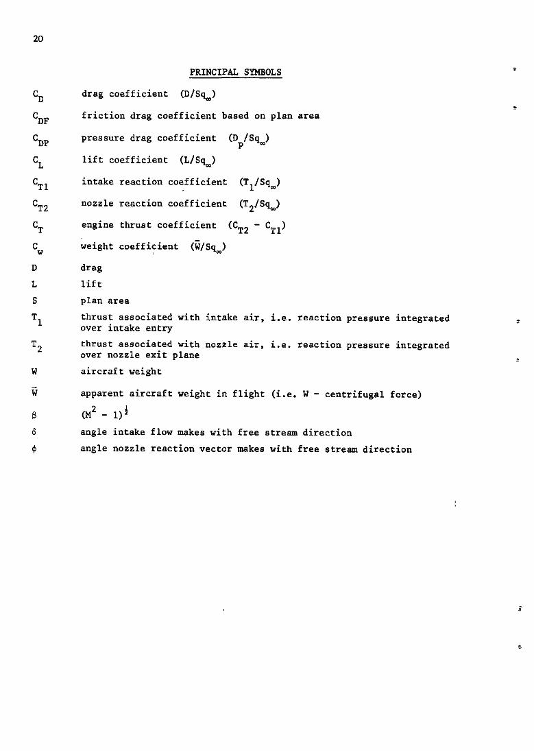
PRINCIPAL SYMBOLS
drag coefficient (D/Sq-)
friction drag coefficient based on plan area
pressure drag coefficient (Dp/Sq,)
lift coefficient (L/Sq_)
intake reaction coefficient ('+,)
nozzle reaction coefficient (T2/%,)
engine thrust coefficient (C T2 - 'Tl) weight coeffiyient (i/Sq_)
drag lift plan area thrust associated with intake air, i.e. reaction pressure integrated over intake entry thrust associated with nozzle air, i.e. reaction pressure integrated over nozzle exit plane aircraft weight
apparent aircraft weight in flight (i.e. W - centrifugal force)
CM2 - 1)' angle intake flow makes with free stream direction angle nozzle reaction vector makes with free stream direction
21
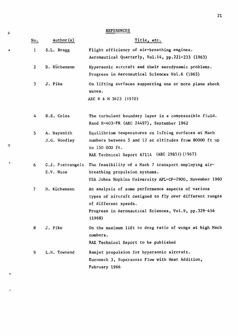
REFERENCES
NO. Author(s) Title, etc. -
1 S.L. Bragg Flight efficiency of air-breathing engines. Aeronautical Quarterly, Vo1.14, pp.221-233 (1963)
2 D. Kiichemann Hypersonic alrcraft and their aerodynamic problems. Progress in Aeronautical Sciences Vol.6 (1965)
3 J. Pike On lifting surfaces supporting one or more plane shock waves.
ARC R & M 3623 (1970)
4 D.E. Coles The turbulent boundary layer in a compressible fluid. Rand R-403-PR (ARC 24497). September 1962
5 A. Naysmith Equilibrium temperatures on lifting surfaces at Mach
J.G. Woodley numbers between 5 and 12 at altitudes from 80000 ft up
to 150 000 ft. RAE TechnIcal Report 67114 (ARC 29851) (1967)
6 G.J. Pletrangell The feasibility of a Mach 7 transport employing air- E.V. Nice breathing propulsion systems.
USA Johns Hopkins University APL-CF-2900, November 1960
7 D. Kiichemann An analysis of some performance aspects of various types of aircraft designed to fly over different ranges of different speeds. Progress in AeronautIcal Sciences, Vo1.9, pp.329-456 (1968)
8 J. Pike On the maximum lift to drag ratio of wings at high Mach
numbers. RAE Technical Report to be published
9 L.H. Townend Ramjet propulsion for hypersonic aircraft. Euromech 3, Supersonic Flow with Heat Addition,
February 1966

6
1 ’ Shock wave
W \Naqht of aacraft In f\lqht L Lift
D Pressure and friction drag TI Stqtlc and momentum prassuras Integrated over Intake entry
Tz Thrust from nozzle ate (saa appendix A)
F1g.l SchematIc diagram of a hypersonic crwse vehicle

0.6
Ground
Proportlon of waiqht
Apparant walqht o-4
0.2
0’ I I \ I y 0 5 IO IS 20 25
M
Fig.2 Influence of centrifugal forces on the apparent weight of an aircraft
Prossure ratlo across shot k wove
O5 6 7 8 a IO
,o’ ,b
Fig.3 Shock wave compression ratio for caret wings
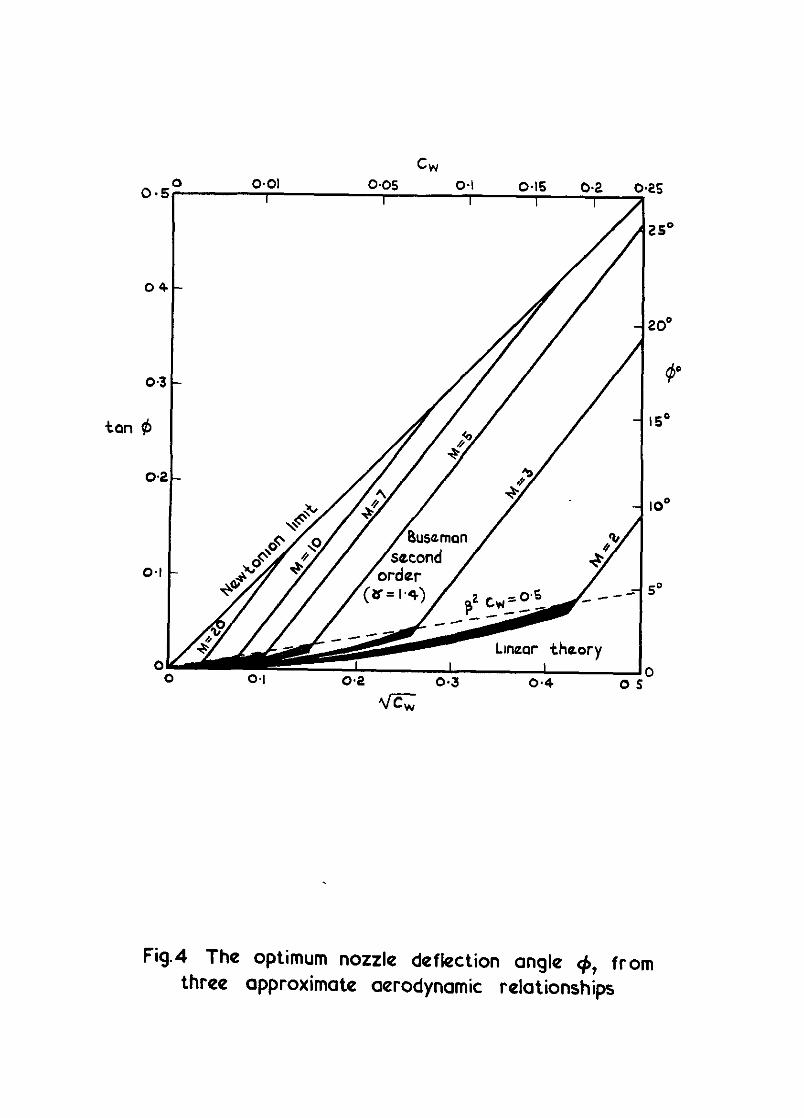
Fig.4 The optimum nozzle deflection angle 4, from three approximate aerodynamic relationships
0.25
0.2
Thrust 2 Apparent we~yht C,
- 01
C 01
o'2 tan $4 c
03r
L /
.M=5 CDF = 0 002
Apl5 = 0 04
04 ( 5
_ M=lO
1 >3
Norzla mclmatlon = tan $
Fig.5 Thrust to weight ratlo for varying nozzle inclination
CL CW
a
b
CL CL
’ ’
mgno lift angno lift
- - = = Cw Cw waight waight -0 -0
CL CL oorodynomic lift oorodynomic lift
Fw= apparant weight Fw= apparant weight
006 006
CW CW 0 0 I2 I2 0.16 0.16 0 to 1.1 0 to 1.1
027----
t
T thrust <= apparent walyh t
b 0.08 GJ
012 0.16 0
4
CL I-- CW
6
Fig.6 aeb klinifMII engim thrust re%dtS, hd=S, CDF=0’002
C
25=
20'
ISC
@
lo’
51
0
d
004 00.3 cw 012 0.16 0
20
I8
I.6
IC
0e
06
04
02
C
-7-r comparlso" dof k&on angla wtth const L/D valua 1
I 1 1 I 4 008 tw 012 0.16 020
Fig.6 cant
101 - n
b
0 - -
010,
0 05
T-thrust W waght
OO 004 0.08 cw 0 12 0 16 0.20
Fig.7aeb Minimum engine thrust results, for M= 7, cDF=o’oo2
C
d
25-
20-
15-
IO-
s-
0 0 0
I # =nozzle thrust
dofloctm angle
Fig.7 cant
0
a
0 25
T i
b C
2
0 0
CL -= oarodynamlc lift
CW wyht
+ Typical value (Rof 9) ,.
0.00 0.12 0 16 020 CW
Fig. 8 aeb Minimum engine thrust results, M= IO, C&=0*002
2t
It
25
1
)
,
) 0
I(
C C
004 0
20
16
14
I
d 0 0
---
c 0
*
@ = nozzle thrust dofloctlon on9ltz I I
3 cw 012 0 16 C
4& I I .- -lx---+-- otonO
-- Comporlson of nozzle - deflectton angle wkh 1 const L/D voluo
-l-L 6 CW
0.12 016 C 10
Fig. 8 cant
CL CW
0
b
08
06
0.4
I I CL -aorodynamc l!Ct -- CW walght
OO 004 0.08 CN 0 12 0 I6 C
-0
-0i
-0
I-
-01
-0
-I ,a:
1
i
1 thrust -=- W walght
0 0 004 0.08
CW 0.12 0 16 0 0
Fig.9 a&b Minimum engine thrust results, for large friction drag M = IO, CDF =0*004
004 004 006 006 cw Ot2 cw Ot2 0 16 0 16
I8
16
I4
12
+a”~ lO---
08
06
02
d 0 0 0
- -
- comparlscn of nozzla - deflectton angle wth Cons’. L/D value 1
3 cw 0 12 0 16 C
Fig.9 cant
08 0 2
06 0
I
04 0
02 0 8
0 0 004 0.08 0 16 0.x
01
0 0 004 00.3 _ 0 12 0 16 02c
4
CL -- CW
6
Fig.lOaab Minimum engine thrust results, for very large friction drag M = IO, CD,= O-01
i
i
- 08 CW CW
0 12 016 C
AP - J'O
ii YflF 4 008 & c
L ) 1; C
/
C
Fig.10 cant

5 CW
a
b
0.10
0 OS
T _ thrust
ii- wolght
0. 0 004 008 CW 0 12 0 16 0.20
2
z
.
4
CL -- CW
8
0
.
Fig. llaeb Minimum engine thrust results, for friction drag varying with CL, M = IO, CDF= 0002 (I + IO CL) .
C
d
18 t I I
--.
0 004 008 cu 0
Fig. I I cant
VISCOUS drag Total drag
VISCCUS drag
Total drag
IO
08
06
04
.
c
--c~F’Oo04 .
-----CDF=Ool
02 - CfJ$ =o 002 (I+lOcL) -
oLLL 0 002 004
cw (
Ap=I ‘,S M
\ ‘\ ‘\
\ ‘. \
Fig.12 Ratio of viscous drag to total drag
I -’ Nowtonm ‘ho I
#=--++M=5 CD,=‘002
02
01
0 01 04 01
.‘l--l--lII?/ - Newtoman Im
04
0.3
I 2 ‘+B
02 002CL
01
0 0.1 0.4 05
Fig.13 Collapsed plots of + values
Frau stream w
dlractlon
a ‘am wing
(I) Intoha (II) Cowl pressure Thrust raactlon - wmg saction prassura components
\
(ii,) Nozzla raactlon
(IV) prassure dlffaranca due to ,ot
b wing + propulsion system
(v) prassure dlfferance dua to cowi
C Two examples ot centre sections
Fig. 14a-c Schematic representation of a llftmg confIguratIon with and wlthout prop&Ion unit
i ARC CP No 1222 533 6 OX 16 June I 1971 533601361
1 533 6 0115
ptke, J 533 6 01155 533 692.55
OPTIMUM ENGINE THRUST DEFLECTlON FOR HIGH-SPEED CRUISING AlRCRAFT
I
At high Mach numbers, an effklent crusmg amxaft wt” have a sgmicmt fract,an of tts weght camed by the e-en A, optimum condams, the praputswe ,e, ,s ,,,cb,,ed to the ho,uantal at an angle Q, given approxtmately by
tan@ = 106 6 - l/(2 48) ,
!
where Cw IS a nondlmenaanabsed aucraft we@t At th,s “gle, the net thrust required ts about 20% less than the ““vectored thrust Also, compared wth values from previous andysls at constant bft-t-to-drag ram, the thrust deflection IE approxmately 50% large,, and the thrust requued 1s typu.Uy 3% smaller
ARC CP No 1222 June 1971 5336013 16 533601361
,!
P&e, 53360115 J 533601155 533 692 55
f
OPTIMUM ENGINE THRUST DEFLECTION FOR ? HIGH-SPEED CRUISING AlRCRAFT ,
J ii
At h,& Mach numbers, an eftictent crulun~ arcraft wdJ have a slgnlficant fractmn of tts we@, came., by the englner A, optmmm wndtttons, the propulsve,et IS lnclrned to the homontal at an angle $, g,ven aFprox,mately by
tanm = 106 & - l/(2 48) . ‘1
where C, IS a nondtmensmnalx., a,,c,af, we,&, At ,h,s angle, the net thmst requued I* IS about 20% less than the unvectored thrust Also, compared wth value, from prevmur dysls at conSlant ltft-todrag ratro, the thmstdeflechon IS aFpraxm,a,ely 50% larger, I and the thrust required ,s typ,ca,ly 3% rmaller I
!
I I I
- --- - ---
DETACHABLE ABSTRACT CARDS / I
t--m-.- - - - - - j _ -Cuthere- -
I
- - --- - ’ - -Cuthere- _ DETACHABLE ABSTRACT CARDS ,
I I I I I I I
----------------------------------------.--~------.---------------- I
---------- ---- -----A ---- --_---_- _
, I I 0 , I
I I
I$- 4) 1 I, t it, 1 .,> ” I, .I ;
1
ARC CP No 1222 June 1971
Pske, J
OPTIMUM ENGINE THRUST DEFLECTION FOR HIGH-SPEED CRUISING AIRCRAFT
I
533601316 1 533 6 013 61 , 533 6 011.5 I 533.6 011.55 I 533 69255 /
1 I 1
At high Mach numbers, an effiaent c,,usmg arrcraft wl, have a ugn,,ica,,t fractmn of I
tts wet&t camed by the engmes At oF,tmum condltmns, the propuluve,et IS mcht,ed 1
to the horuontal at an angle 0, @“en aF,xoxm,a,ely by I I
tall@ - 106 < - l/2 48) ,
where C, 1s a nondtmenslo”ahsed arcraft we,@,, A, tb,s angle, the net ,hms, required II about 20% less than the ““vectored thrust Also, comgraed wth values from prenous
;
analysis at COnStan, bft-todrag ratm, the thrust denectlon IS approxlmate,y 5046 larger. /
and the thrust required LS typtcauy 3% smaller , 1 I I , I
- - - _- - - - f-----Q .-._-.--_ “,_----~---_---__-___-.- ____ - _____._.__________ -__.______
,

C.P. No. 1222
@ CROWN COPYRIGHT 1972
HER MAJESTY’S STATIONERY OFFICE
49 H@ Holborn, London WCIV 6HB L3aCastle Street, Edmburgh EH2 3AR
109 St Mary S,reet,Card,ffCFI ,IW Brazennose Street, Manchester MO *AS
50 Falrfax Street, Bmtol BSI 3DE
258 Broad Street. Bm,“ghm B1 2HE 80 Chichester Street. Belfast BT1 41,’
C.P. No. 1222
SBN 11 470780 4