options for mitigating environmental pollution from energy...
TRANSCRIPT

x
SMR 1585 - 10
___________________________________________________________
WORKSHOP ON DESIGNING SUSTAINABLE ENERGY SYSTEMS18 October - 5 November 2004
___________________________________________________________
Options for Mitigating Environmental Pollution fromEnergy Production and Uses
Chae Young LIMK.A.E.R.I., Korea Atomic Energy Research Institute,
Nuclear Policy Division, Daejeon, Korea
___________________________________________________________________These are preliminary lecture notes, intended only for distribution to participants.

Options for Mitigating Environmental
Pollution from Energy Production and
Uses
Chae Young Lim([email protected])

How to reduce the emission in the energy system?
Demand side management• Industrial shift to Low energy intensity • Energy Saving • Efficiency Improvement
Supply side measures• Control technologies with fossil fuel combustion
• Fuel treatment (SO2)• Combustion modification (NOx)• Post-combustion control (SO2, NOx, PM)
• Fuel switching• Alternative energy technology

Air pollutants emitted by Fossil Fuel-Fired Power Plants
Particulate Matter (PM)Sulfur Oxides (SOX)Nitrogen Oxides (NOX)Carbon Dioxide (CO2)Carbon Monoxide (CO)Volatile Organic Compounds (VOC)Air Toxics (heavy metals, organics, etc.)

PARTICULATE MATTER ABATEMENT TECHNOLOGIES

Emission Control Techniques for Particulate Matter(PM)
Principle control techniques are post-combustion methods
• Electrostatic precipitators (ESP)
• Fabric filters (or baghouse)
• Wet scrubber
• Cyclone separator or multiclone collector
• Side stream separator
In case of small stoker-fired boilers, combustion modifications can reduce the PM emissions
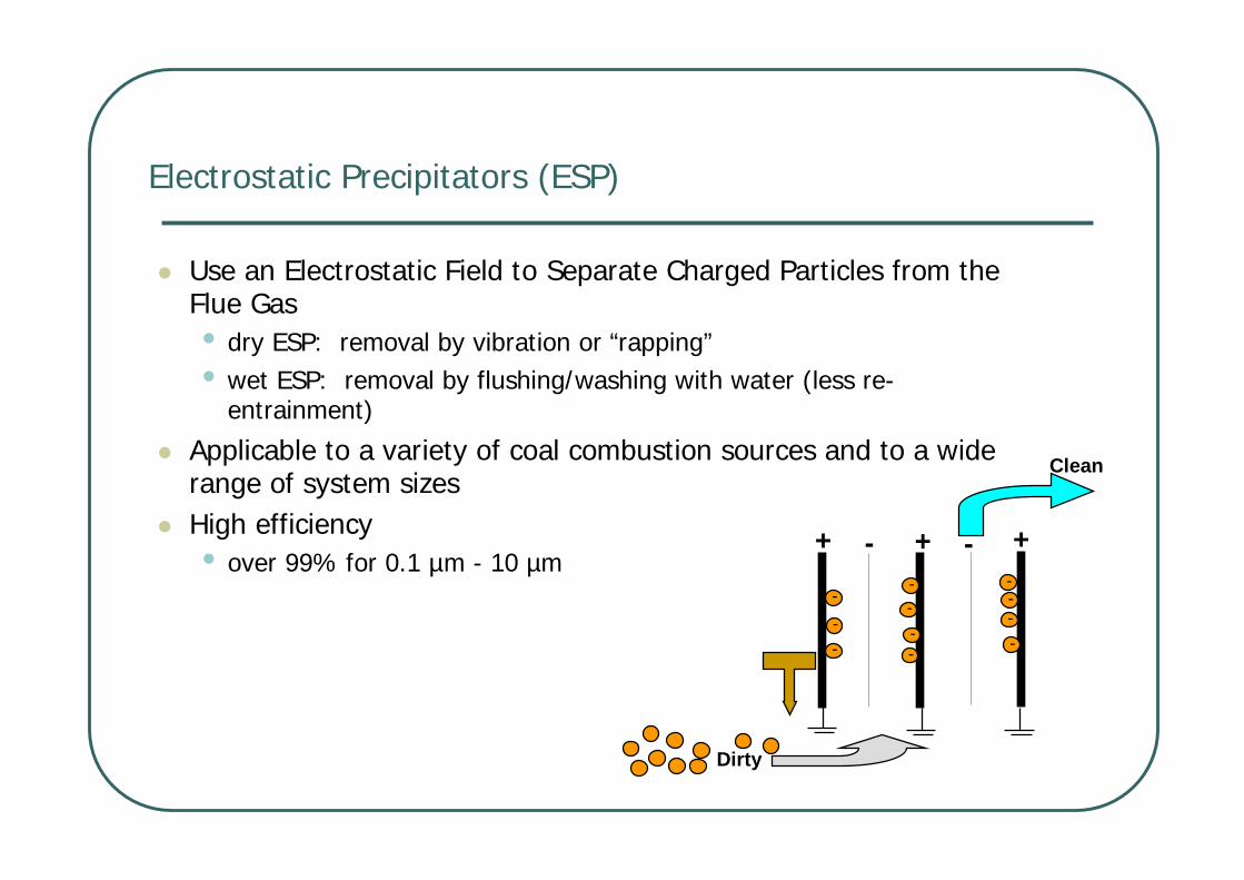
Electrostatic Precipitators (ESP)
Use an Electrostatic Field to Separate Charged Particles from the Flue Gas• dry ESP: removal by vibration or “rapping”• wet ESP: removal by flushing/washing with water (less re-
entrainment)
Applicable to a variety of coal combustion sources and to a widerange of system sizes High efficiency• over 99% for 0.1 µm - 10 µm
+ + +- ----
----
----
Clean
Dirty

Cost of ESPs
Typical costs of a new ESP: US$40 ~ 60/kW • designed to remove 99.0 to 99.7 percent PM• Higher collection efficiency may increase the
cost up to 100 US$/kW
Typical O&M costs of conventional ESP: 2 ~ 4 US$/MWh

Fabric Filters (Baghouse)
Particles and flue gas are separated in tube-shaped filter bagsMain Alternative to ESPs for Large Coal-Fired Power PlantsWidely used in the developed countries mostly since early 1970sCollection efficiency: upto 99.9%

Cost Effectiveness of Baghouses
In general, ESPs are more competitive than baghouses
• lower capital and levelized costs for collection efficiency below 99.0 to 99.5%
In cases in which more than 99.5% collection
efficiency is required, especially for low-sulfur coals, baghouses are more cost-effective
Typical costs for baghouses: US$50 ~ 70/kW
Levelized costs: 3.5 to 4.5 US$/MWh for baghouses

Top View
Side ViewDirty Air
Dirt
y A
ir
Collected Dust
Cleaned Air
Cyclone separator
Make Use of Gravity and InertiaSimpler and Relativelyinexpensive TechnologyCan be installed singly, in series or grouped as in a multiclone collectorOften used as a precollectorupstream of an ESP, fabric filter, or wet scrubber Relatively ineffective for collection of PM-10(particles less than 10 micron)
• Overall collection efficiency: 90-95%

SOX
ABATEMENT TECHNOLOGIES

Emission Control Technologies for Sulfur Dioxide (SOX)
Switch to low sulfur coals
Remove sulfur from fuel (cleaning)
Advanced combustion techniques(e.g., fluidized bed combustion)
Remove SOX from combustion flue gas using post-combustion emission control technology • e.g. flue gas desulfurization (FGD) techniques

Switch to Low Sulfur coals
Typical sulfur contents in coal is 0.5% ~ 5.0%Break point between high and low sulfur coal • 1,100 ng/J (2.5 lbs SO2/million BTU)• Equivalent to 1.5% sulfur (bituminous), 1% sulfur (subbituminous)
Can be used in Pulverized coal(PC) and Fluidized bed combustion(FBC) boilers• In the case of PC systems, substitutions are limited
Low sulfur coal, in general, may be connected with the followingproblems• higher ash content• lower heating value• more moisture• may degrade ESP performance: higher resistivity of the fly ash
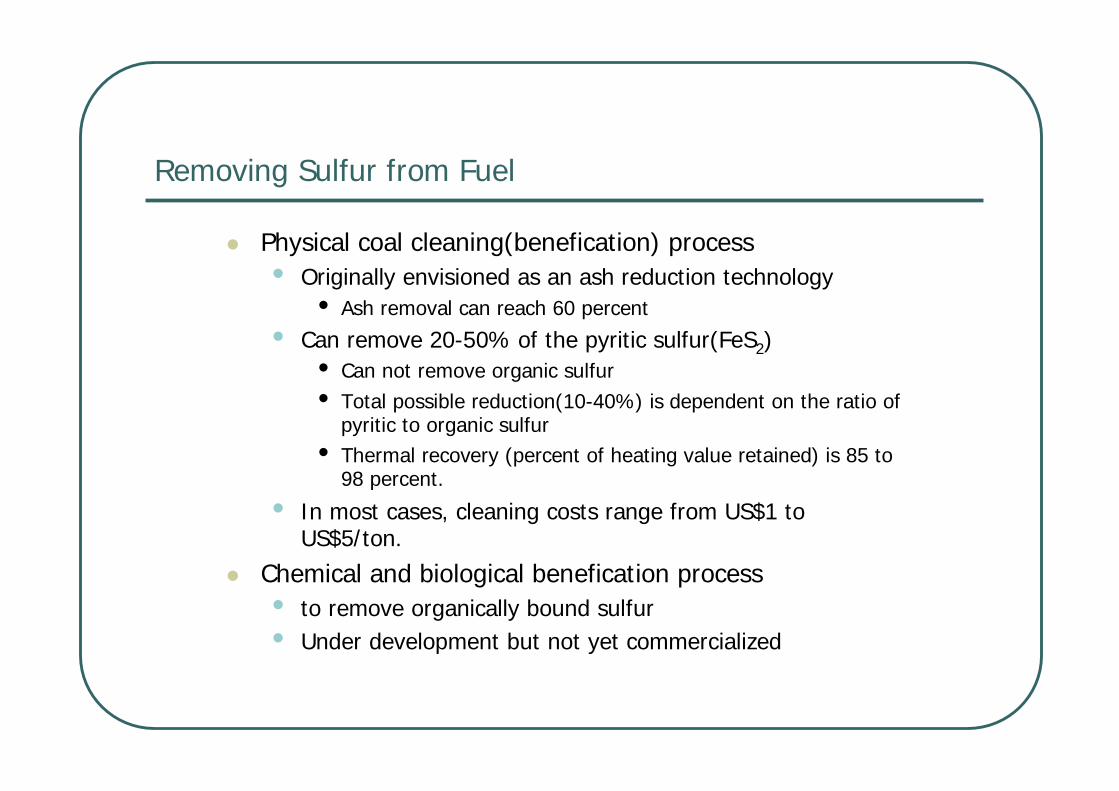
Removing Sulfur from Fuel
Physical coal cleaning(benefication) process• Originally envisioned as an ash reduction technology
• Ash removal can reach 60 percent
• Can remove 20-50% of the pyritic sulfur(FeS2)• Can not remove organic sulfur• Total possible reduction(10-40%) is dependent on the ratio of
pyritic to organic sulfur• Thermal recovery (percent of heating value retained) is 85 to
98 percent.
• In most cases, cleaning costs range from US$1 to US$5/ton.
Chemical and biological benefication process• to remove organically bound sulfur• Under development but not yet commercialized

Fluidized bed combustion boiler(FBC)
Coal combustion occurs within a bed of either sorbent or inert material (usually sand), fluidized by an upward flow of air• Calcium-based limestone or dolomitic sorbent is often used• Bed temperature are maintained between 760-870℃ to promote
the sulfation reactionIt can lower SO2 and NOx emissions• Sulfur is retained as a solid sulfate and is removed from the flue
gas stream by the particulate control device• NOx are reduced because it can operate at lower combustion
temperature (well below the threshold where nitrogen oxides form, 1400℃), thus reducing the fixation of atmospheric nitrogen
It may tax conventional particulate control system• Particulate mass concentration is 2-4 times higher than PC-boilers
Two different types• Atmospheric FBC• Pressurized FBC

Atmospheric Fluidized Bed Combustion (AFBC)
Projected capital costs: US$1000 to 1300/kW(150-300 MW AFBC) • AFBC technology is the technology of choice when
• fuel flexibility is desirable, • low-quality fuels are available, • low-NOx emissions are required, • medium (70 to 90 percent) SO2 removal is desired
SO2 removal
- Bubbling AFBC: 70-90%
- Circulating AFBC: up to 95 %

Pressurized Fluidized Bed Combustion (PFBC)
Boiler operates at higher than atmospheric pressure (0.5 to 2 MPa)• the gas is cleaned downstream from the PFBC boiler, and the gas is expanded in a
gas turbine
Projected capital costs: US$1150 to 1250/kW• fuel flexibility, modularity, and suitability for retrofit
SO2 removal
-more than 90%
Thermal Efficiency
-40-42% with combined cycle

Post-combustion SO2 control for coal combustion
Several research and development, and demonstration projects underway, not yet commercially available
25 - 50+% Dry sorbent injection into duct, sometimes combined with water spray
Duct injection
Commercialized in Europe, several U. S. demonstration projects are completed
25 - 50% Dry calcium carbonate/hydrate injection in upper furnace cavity
Furnace injection
Applicable to low and medium sulfur fuels, produces dry product
70 - 90% Calcium hydroxide slurry, vaporizes in spray vessel
Spray drying (Dry FGD)
Uses lime to regenerate sodium-based scrubbing liquor 90 - 96% Dual alkali
Can be regenerated 80 - 95+% Magnesium oxide/ hydroxide
5-430 million Btu/hr typical application range, high reagent costs
80 - 98% Sodium carbonate
Applicable to high sulfur fuels, wet sludge product 80 - 95+% Lime/limestone
Wet scrubber(Wet FGD)
Remarks Typical Control Efficiencies Process Control Technology

Wet Scrubber (wet FGD)
Use an alkaline reagent slurry to absorb SO2 in the Flue GasMany variations for wet FGDs (limestone forced oxidation, dual alkali, ammonia, sodium carbonate)
SO2 removal
- 80-95%
- 95-99%(with additive)
Power usage
-1-2% of total generating capacity

Cost-Effectiveness of Wet FGD
Adding a wet FGD onto an existing power plant (retrofit) is typically more expensive than the same wet FGD for a new power plantCosts typically vary by size, sulfur content of coal, etc
Cost Factor Retrofit New Plant
Capital Cost (US$/kW) 100 - 150 70 - 150
Variable O&M (USmills/kWh) 1.5 - 3.3 1.3 - 3.2
Total O&M (USmills/kWh) 6.6 -12.0 7.4 - 13.0
Costs are expressed in 1990 US$
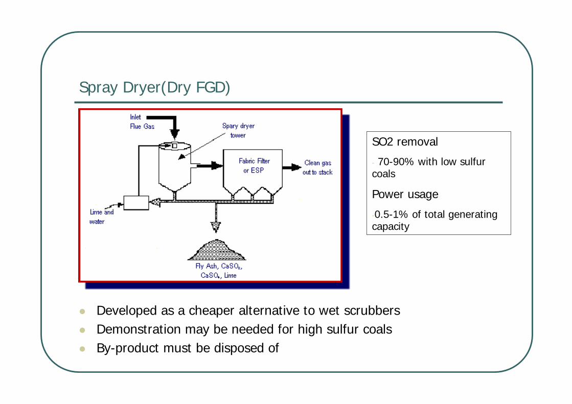
Spray Dryer(Dry FGD)
SO2 removal
- 70-90% with low sulfur coals
Power usage
-0.5-1% of total generating capacity
Developed as a cheaper alternative to wet scrubbersDemonstration may be needed for high sulfur coalsBy-product must be disposed of

Cost Effectiveness of Dry FGDs
Costs are lower than for wet FGDs because the system is simpler and easier to operate and maintainAs wet FGDs are being simplified and costs are reduced, it becomes more difficult for dry FGDs to compete based on cost-effectiveness ($/ton of SO2 removed) considerations
Cost Factor Retrofit New Plant
Capital Cost (US$/kW) 140-210 110-165
Variable O&M (USmills/kWh) 2.1-3.2 2.1-3.2
Total O&M (USmills/kWh) 6.0-9.0 7.4 - 11.0
Cost data reflects 1990-92 experience

Sorbent Injection
Sorbent can be injected at different locations• Furnace Sorbent Injection: the injection point is above the burners or in
the backpass before the air heater• Duct Injection: injection in the duct before or after the ESP• Different types of sorbents can be used
• Limestone, hydrated lime or dolomite
Coal
ESP
Stack
Furnace
Furnace sorbent injection pre-ESP duct injection
post-ESP duct injection

Cost effectiveness of Sorbent Injection
Sorbent injection is simple and has lower capital and operating costs than scrubbers• Other advantages of the technology are that it requires very little space,
uses readily available additives (sorbent), and is easy to operate and maintain
but it has limited SO2 removal (30 to 60 percent) capability Capital cost: 70-120 US$/kW variable operating cost: 3-7 USmills/kWh. Sorbent injection is typically used for retrofit applications

NOX ABATEMENT TECHNOLOGIES

Emission Control Technologies for NOX
Operational modifications• Changing certain boiler operational parameters can create conditions in
the furnace that will lower NOx production. • e.g. Burners-out-of-service (BOOS), Low excess air (LEA), Biased firing
(BF)
Combustion modifications• designed to ‘staged’ combustion • e.g. NOx Burners, Overfire Air, Reburning, Flue Gas Recirculation
Post-combustion treatment• reducing agent (typically NH3) is injected and it reacts with NOx• e.g. Selective Catalytic Reduction, Selective Noncatalytic Reduction,
Hybrid Processes

Combustion and Post-combustion NOx Control Options

Characteristics of Combustion modification
Commercially available but not widely demonstrated
50 -60Pulverized coal boilers, cyclone furnaces
Injection of reburn fuel and completion air above main combustion zone Reburn
Available 40 -60Pulverized coal boilers Combination of new burner designs and injection of air above main combustion zone
LNB with OFA
Available 35 -55Pulverized coal boilers New burner designs controlling air-fuel mixing
Low NOxBurners
Available 20 -30Pulverized coal boilers and stokers
Injection of air above main combustion zone Overfire Air
Available 10 -20Pulverized coal boilers (some designs); Stokers
Rearrangement of air or fuel in the main combustion zone
Operational modifications
Commercial Availability/R & D
Status
NOx Reduction Potentialb (%)
Applicable Boiler DesignsDescription of TechniqueControl Technique

Low NOX Burners
Are designed to stage combustionA fuel-rich zone is created by forcing additionalair to the outside of the firing zone (auxiliary air) andby delaying the combustion of coal
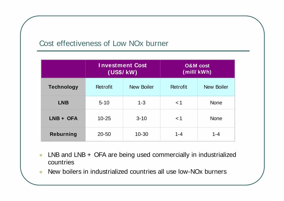
Cost effectiveness of Low NOx burner
LNB and LNB + OFA are being used commercially in industrialized countriesNew boilers in industrialized countries all use low-NOx burners
Investment Cost(US$/kW)
O&M cost(mill/kWh)
Technology Retrofit New Boiler Retrofit New Boiler
LNB 5-10 1-3 <1 None
LNB + OFA 10-25 3-10 <1 None
Reburning 20-50 10-30 1-4 1-4

Characteristics of Post-Combustion emission control
Commercially offered, but not widely demonstrated as a combined technology
85-95Pulverized coal boiler Combination of new burner design, injection of air above combustion zone, and injection of NH3 or urea
LNB with OFA and SCR
Commercially offered, but not widely demonstrated as a combined technology
50-80Pulverized coal boilers Combination of new burner designs and injection of NH3 or urea LNB with SNCR
Commercially offered, but not yet demonstrated
75 -85Pulverized coal boilers, cyclone furnaces
Injection of NH3 in combination with catalyst material SCR
Commercially available but not widely demonstrated
30 -60
Pulverized coal boilers, cyclone furnaces, stokers, and fluidized bed boilers
Injection of NH3 or urea in the convective pass SNCR
Commercial Availability/R & D
Status
NOx Reduction Potentialb (%)
Applicable Boiler DesignsDescription of TechniqueControl
Technique

Selective Non-Catalytic Reduction (SNCR)
The technology was initially demonstrated in boilers fired by oil or natural gas
Urea(CH2CONH2) is injected into the flue gas to convert NOX to elemental nitrogen and water
The chemical reactions, in a simplified form are as follows
• 2NO + NH2CONH2 + ½O2 2N2 + CO2 + 2H2O
Uses higher furnace temperatures (900-1100℃)
1-21-2Operating cost
(mills/kWh)
5-1010-20Investment cost
(US$/kW)
New plantretrofit

Selective Catalytic Reduction (SCR)
Ammonia is injected into the flue gas to convert NOX to elemental nitrogen and water using a catalyst
• The catalyst is needed because SCR systems operate at much lowertemperatures (340 to 380°C)
• The most commonly used catalysts are a vanadium/titanium formulation (V2O5 stabilized in a TiO2 base) and zeolite materials

Cost-Effectiveness of SCR
Capital costs depend on • the required NOx emission reduction• unit layout (available space and interferences)• catalyst unit price • cost of ammonia• type of SCR (hot-side vs. post-FGD)
O&M costs for SCR depend on • the catalyst life (typically 3 to 5 years)• the catalyst cost (typically 16.000-20,000 US$/m3)
2-42-4Operating cost
(mills/kWh)
90-15050-90Investment cost
(US$/kW)
New plantretrofit

CO2 ABATEMENT TECHNOLOGIES

CO2 Abatement Approach
Fuel substitution into lower CO2 emission
Improving plants efficiency• Less coal is burned(producing less CO2) for the same power output• Enhanced steam condition -> efficiency reach above 40%• Advanced coal technology such as PFBC, IGCC
CO2 capture• Flue gas approach - Capture CO2 from the combustion flue gas• Oxygen combustion• Hydrogen(Syn-Gas)

Absorption• Chemical absorption: Chemical stripping with solvents such as mono-
ethanolamine (MEA), di-ethanolamine (MEA), etc.• Physical absorption: commonly used in commercial processes
Adsorption• Separate CO2 by adsorption with some materials with high surface areas such
as zeolites and activated carbon• Pressure Swing Adsorption(PSA), Temperature Swing Adsorption(TSA),
Electrical Swing Adsorption(ESA)
Cryogenics/CO2 recycle• CO2 is cooled below its boiling point, and turn into the liquid state• Requires too much energy and is uneconomic
Membranes• Barrier film that allows selective and specific permeation• Gas separation membranes and gas absorption membranes
Flue gas approach

Amines Separation Process(MEA)
Widely used in removing CO2 from natural gas reservoirsCO2 in the flue gas comes in contact with the MEA solution in the absorberThe MEA selectively absorbs the CO2 and is then sent to a stripperIn the stripper, the CO2-rich MEA solution is heated to release almost pure CO2
The lean MEA solution is recycled to the absorber

Oxygen Combustion Approach
Increases CO2 concentrations by increasing O2 levels and reducing N2 contents in the combustion air• With higher O2 concentrations, the flue gas is then re-circulated to control
combustion temperature
Advantage: the volume of inert gas is reduced, which can increase boiler thermal efficiencyDrawback: the production of O2 using conventional cryogenic air separation plants is expensive, therefore, the process is highly inefficient

Hydrogen/Syngas approach
a pre-combustion capture technology that removes the carbon content (“decarbonizes”) of fossil fuels, and produces a CO2-rich by-product stream It is an approach used for both H2 production and electricity generationWhen electricity (rather than H2) is the desired product, coal is gasified in an IGCC power plant to produce a syngas consisting of CO and H2
The syngas can then be used in a gas turbine and the highly concentrated CO2 can be captured and stored

CO2 Sequestration Options & Mechanisms
Hydrodynamic trapping: trapped as a gas
Solubility trapping: dissolves into the fluids
Mineral trapping: reacts directly or indirectly with minerals to become part of solid mineral matrix

Capacity of potential CO2 storage sites
Total worldwide anthropogenic CO2 emissions are the equivalent of about 7 GtCPotential worldwide CO2 storage capacity is enormous
<1 GtC/yrUtilization
10s GtCTerrestrial Ecosystems
10s—100s GtCCoal Seams
100s GtCDepleted Oil and Gas Reservoirs
100s—1000s GtCDeep Saline Formations
10002 GtCOcean
Worldwide CapacitySequestration Option

Projected Cost of CO2 Capture & Sequestration
CO2 capture
• the costs of capturing CO2 from various fossil power plants range from US$16-87 per tonne CO2 avoided
• NGCC with capture via amine scrubbing of flue gas and IGCC with pre-combustion capture of CO2 as the two most promising options
CO2 transportation & sequestration
• transport by pipeline costs around $1–$3 per ton
• transport and storage costs are somewhere between 5-21/ton CO2
depending on transport distance and storage method
• Costs are about one third of the total CO2 cost for sequestration projects

References
http://www.iea-coal.org.uk/
http://www.worldbank.org/html/fpd/em/power/EA/mitigatn/thermair.htm
http://www.epa.gov/ttn/chief/ap42/index.html
http://www.netl.doe.gov/