optomux protocol user’s guide
TRANSCRIPT

OPTOMUX PROTOCOLUSER’S GUIDE
Form 203-020107 — January, 2002
43044 Business Park Drive, Temecula, CA 92590-3614Phone: 800/321-OPTO (6786) or 951/695-3000
Fax: 800/832-OPTO (6786) or 951/695-2712Internet Web site: www.opto22.com
Product Support Services:800/TEK-OPTO (835-6786) or 951/695-3080
Fax: 951/695-3017E-mail: [email protected]
Bulletin Board System (BBS): 951/695-1367http://bbs.opto22.com
(24 hours a day, 7 days a week)

2 Optomux Protocol User’s Guide
Optomux Protocol User’s GuideForm 203-020107—January, 2002
The information in this manual has been checked carefully and is believed to be accurate; however, Opto 22assumes no responsibility for possible inaccuracies or omissions. Specifications are subject to change withoutnotice.
Opto 22 warrants all of its products to be free from defects in material or workmanship for 30 months from themanufacturing date code. This warranty is limited to the original cost of the unit only and does not coverinstallation, labor, or any other contingent costs. I/O modules and solid-state relays with date codes of 1/96 or laterare guaranteed for life. This lifetime warranty excludes reed relay and dry contact modules. Refer to Opto 22 formnumber 1042 for more details.
Opto 22 FactoryFloor, Cyrano, Optomux, Pamux, SNAP I/O, Generation 4, and Mistic are registered trademarks ofOpto 22. OptoConnect, OptoControl, OptoServer, and OptoDisplay are trademarks of Opto 22.
ARCNET is a registered trademark of Datapoint Corporation.
IBM is a registered trademark and IBM PC, XT, AT, and PS/2 are trademarks of International Business MachinesCorporation.
Microsoft and MS-DOS are registered trademarks and Windows is a trademark of Microsoft Corporation.

Optomux Protocol User’s Guide 3
Table of Contents
Welcome.................................................................................................. 9Overview ............................................................................................................................... 9
What's In This Guide?........................................................................................................ 9
Document Conventions ................................................................................................. 10
Chapter 1: Introduction ........................................................................ 11Overview .............................................................................................................................11
System Configuration..................................................................................................... 12Physical Layout ......................................................................................................... 12Communications ...................................................................................................... 12Modular Construction ............................................................................................ 12Wiring ......................................................................................................................... 13Data Transmission..................................................................................................... 13System Throughput ................................................................................................. 13Features ...................................................................................................................... 14
Digital Optomux .............................................................................................................. 14Latched Inputs .......................................................................................................... 14Time Delays ................................................................................................................ 15Pulse Generation...................................................................................................... 15Event Counting ........................................................................................................ 15Pulse Duration Timers ............................................................................................. 15
Analog Optomux ............................................................................................................. 15Analog Input Averaging ........................................................................................ 15High/Low Limit Testing ........................................................................................... 15Output Waveform Generation .............................................................................. 15High/Low Value Recording .................................................................................... 16Gain and Offset Calculation .................................................................................. 16
Summary ............................................................................................................................ 16
4 Optomux Protocol User’s Guide
Chapter 2: Installation and Wiring .......................................................17Physical Installation ........................................................................................................ 17
Mounting................................................................................................................... 17
Communications Wiring ................................................................................................ 18Host to First Optomux ............................................................................................. 18Optomux to Optomux............................................................................................. 19Installing Digital I/O Modules ............................................................................... 20Installing Analog I/O Modules .............................................................................. 21
Power Requirements ....................................................................................................... 22Connect Power Supply ........................................................................................... 22
Third-Party power supply vendors .............................................................................. 24
Brain Board Mounting ................................................................................................... 25
Selecting The Jumpers .................................................................................................... 26Information Required ............................................................................................. 26Group A Jumpers...................................................................................................... 26Group B Jumpers ...................................................................................................... 27
Accessories ......................................................................................................................... 29
Chapter 3: Programming ...................................................................... 31Overview ............................................................................................................................ 31
Building Command Messages ....................................................................................... 32Beginning .................................................................................................................. 32Middle ........................................................................................................................ 32End .............................................................................................................................. 32How Optomux Represents Numbers .................................................................... 32Building The Beginning Of A Command Message ........................................... 33Building The Middle Of A Command Message ................................................. 33Building The End Of A Command Message ....................................................... 34
Carrying Out Message Transactions ............................................................................. 352-Pass Mode .............................................................................................................. 354-Pass Mode .............................................................................................................. 35Interpreting the Response ..................................................................................... 36
Error Codes ........................................................................................................................ 36Acknowledge ............................................................................................................ 37Acknowledge with Data ......................................................................................... 37
Initializing An Optomux Network................................................................................ 38
Serial Port Configuration............................................................................................... 39
Interpreting Analog Data .............................................................................................. 39Analog Outputs ........................................................................................................ 39Analog Inputs ........................................................................................................... 40Offset and Gain ........................................................................................................ 42

Optomux Protocol User’s Guide 5
Chapter 4: Command Directory ............................................................43Optomux Command Summary ..................................................................................... 43
COMMAND NAME/COMMAND FORMAT ........................................................................ 43
Operational Differences — Old Optomux Brain boards .......................................... 48Digital Brain Boards (B1) ........................................................................................ 48Analog Brain Boards (B2) ....................................................................................... 48
Command Enhancements .............................................................................................. 49Digital ........................................................................................................................ . 49Analog ........................................................................................................................ 49
Command Usage Recommendations ........................................................................... 50
Chapter 5: Setup Commands ................................................................ 51POWER-UP CLEAR .............................................................................. COMMAND A 51RESET ..................................................................................................COMMAND B 52SET TURNAROUND DELAY ....................................................................COMMAND C 53SET DIGITAL WATCHDOG ..................................................................... COMMAND D 54SET ANALOG WATCHDOG.................................................................... COMMAND D 55SET PROTOCOL ..................................................................................... COMMAND E 57IDENTIFY OPTOMUX TYPE ..................................................................... COMMAND F 58SET ENHANCED DIGITAL WATCHDOG ................................................ COMMAND m 59SET ANALOG WATCHDOG USER-DEFINED VALUE.............................. COMMAND m 60SET TIMER RESOLUTION .......................................................................COMMAND n 61SET TEMPERATURE PROBE TYPE ........................................................... COMMAND k 62
Chapter 6: I/O Configuration Commands ........................................... 65CONFIGURE POSITIONS ....................................................................... COMMAND G 65CONFIGURE AS INPUTS ...................................................................... COMMAND H 66CONFIGURE AS OUTPUTS ..................................................................... COMMAND I 67READ MODULE CONFIGURATION .......................................................... COMMAND j 68
Chapter 7: Digital Read/Write Commands ......................................... 69WRITE OUTPUTS .................................................................................. COMMAND J 69ACTIVATE OUTPUTS ............................................................................. COMMAND K 70DEACTIVATE OUTPUTS .......................................................................... COMMAND L 71READ ON/OFF STATUS ...................................................................... COMMAND M 72
Chapter 8: Digital Latch Commands................................................... 73SET LATCH EDGES ............................................................................... COMMAND N 73SET OFF-TO-ON LATCHES .................................................................. COMMAND O 74SET ON-TO-OFF LATCHES ...................................................................COMMAND P 75READ LATCHES ................................................................................... COMMAND Q 76READ AND CLEAR LATCHES ................................................................ COMMAND R 77CLEAR LATCHES ................................................................................... COMMAND S 78

6 Optomux Protocol User’s Guide
Chapter 9: Digital Counting Commands ...............................................79Start/Stop Counters ...................................................................... Command T 79Start Counters ............................................................................... Command U 80Stop Counters ............................................................................... Command V 81Read Counters ............................................................................. Command W 82Read And Clear Counters ........................................................... Command X 84Clear Counters .............................................................................. Command Y 85
Chapter 10: Digital Time Delay/Pulse Commands .................................87Set Time Delay ............................................................................... Command Z 87Retrigger Time Delay ................................................................... Command h 89Generate N Pulses ..........................................................................Command i 90Start On Pulse ................................................................................ Command k 91Start Off Pulse .................................................................................Command l 92
Chapter 11: Digital Pulse Duration Measurement Commands.............93Set Pulse Trigger Polarity ............................................................Command a 93Trigger On Positive Pulse ........................................................... Command b 94Trigger On Negative Pulse ..........................................................Command c 95Read Pulse Complete Bits ........................................................... Command d 96Read Pulse Duration Counters ...................................................Command e 97Read And Clear Duration Counters .......................................... Command f 98Clear Duration Counters ............................................................ Command g 99
Chapter 12: Analog Read/Write Commands ....................................... 101Write Analog Outputs .................................................................. Command J 101Update Analog Outputs .............................................................. Command S 102Read Analog Outputs .................................................................. Command K 103Read Analog Inputs ...................................................................... Command L 104Read And Average Inputs ......................................................... Command M 105Start Input Averaging .................................................................. Command T 106Read Average Complete Bits .......................................................Command i 107Read Input Average Data........................................................... Command U 108Read Temperature Inputs .............................................................Command l 109Read Average Temperature Inputs ........................................... Command o 111
Chapter 13: Analog Input Range Commands ..................................... 113Set Input Range ........................................................................... Command N 113Read Out-Of-Range Latches ...................................................... Command O 114Read And Clear Out-Of-Range Latches................................... Command P 115Clear Out-Of-Range Latches ...................................................... Command Q 116Read Lowest Values ......................................................................Command a 117Clear Lowest Values ..................................................................... Command b 118Read And Clear Lowest Values ...................................................Command c 119

Optomux Protocol User’s Guide 7
READ PEAK VALUES ............................................................................ COMMAND d 120CLEAR PEAK VALUES ........................................................................... COMMAND e 121READ AND CLEAR PEAK VALUES ......................................................... COMMAND f 122
Chapter 14: Analog Gain/Offset Commands.................................... 123CALCULATE OFFSETS ............................................................................ COMMAND g 123SET OFFSETS ...................................................................................... COMMAND W 125CALCULATE AND SET OFFSETS .............................................................COMMAND h 127CALCULATE GAIN COEFFICIENTS ..........................................................COMMAND X 129SET GAIN COEFFICIENTS ...................................................................... COMMAND Y 131CALCULATE AND SET GAIN COEFFICIENTS ............................................ COMMAND Z 132
Chapter 15: Analog Waveform Commands ..................................... 135SET OUTPUT WAVEFORM.................................................................... COMMAND R 135IMPROVED OUTPUT WAVEFORMS ........................................................ COMMAND V 137
Chapter 16: Revision Identification Commands............................... 139CHECKSUM ON ROM ......................................................................... COMMAND _ 139DATE OF FIRMWARE............................................................................. COMMAND ‘ 140
Appendix A......................................................................................... 141HEX - ASCII Character Table ....................................................................................... 141
HEX To Binary Conversion Table................................................................................. 142
Appendix B ......................................................................................... 143Implementing Drivers for Optomux .......................................................................... 143
Appendix C ......................................................................................... 145Surge Protection For RS-422/485 Communication Links .................................... 145
Appendix D......................................................................................... 147Troubleshooting Questions and Answers ................................................................. 147
Product Support................................................................................. 151
Updated: May 25, 2001

8 Optomux Protocol User’s Guide

Optomux Protocol User’s Guide 9
Welcome
Overview
Opto 22’s Optomux system provides low-cost distributed access to both digital and analog I/O. Using a simple serialport with an RS-485 converter up to 4095 I/O points can be accessed over a distance of several thousand feet atmoderate speeds with high reliability.
This manual describes the protocol used by Optomux to aid in implementing Optomux driver or custom hardwarethat uses Optomux protocol. Commands supported by Optomux digital and analog I/O are described.
C source code called ‘Generic Optomux Driver’ is available in the OptoDriver Toolkit. This driver is helpful for thosedeveloping their own Optomux driver. Optomux drivers are available in the OptoDriver Toolkit for DOS, Win16 andWin32.
NOTE: Information in this manual relating to Pamux brain boards applies only to the revisions of the brain boardsindicated below:
• AC28: Revision C or later. For revision B or earlier, request Opto 22 form #218.
• B4: Revision L or later. For revision K or earlier, request Opto 22 form #127.
• B5: Revision J or later. For revision I or earlier, request Opto 22 form #145.
• B6: Revision G or later. For revision F or earlier, request Opto 22 form #154.
What’s In This Guide?
This guide includes the following sections:
Chapter 1, “Introduction”—overview of Optomux Protocol and hardware.
Chapter 2, “System Setup”—Optomux communication wiring, power wiring, installation, and jumpers.
Chapter 3, “System Setup”—description of protocol.
Chapter 4, “System Setup”—Command directory — Index of Optomux commands.
Chapter 5, “Setup Commands”
Chapter 6, “I/O Configuration Commands”

10 Optomux Protocol User’s Guide
Chapter 7, “Digital Read/Write Commands”
Chapter 8, “Digital Latch Commands”
Chapter 9, “Digital Counting Commands”
Chapter 10, “Digital Time Delay/Pulse Commands”
Chapter 11, “Digital Pulse Duration Measurement Commands”
Chapter 12, “Analog Read/Write Commands”
Chapter 13, “Analog Input Range Commands”
Chapter 14, “Analog Gain/Offset Commands”
Chapter 15, “Analog Waveform Commands”
Appendix A, “Hex/Binary Conversion Tables”
Appendix B, “Implementing Drivers for Optomux”
Appendix C, “Surge Protection For RS-422/485 Communication Links”
Appendix D, “Troubleshooting Questions and Answers”
Appendix E, “Product Support”—information on how to get help from Opto 22.
Document Conventions
• Bold typeface indicates text to be typed. Unless otherwise noted, such text may be entered in upper orlower case. (Example: “At the DOS prompt, type cd \windows.”)
• Italic typeface indicates emphasis and is used for book titles. (Example: “See the OptoControl User’s Guidefor details.”)
• File names appear in all capital letters. (Example: “Open the file TEST1.TXT.”)
• Key names appear in small capital letters. (Example: “Press SHIFT.”)
• Key press combinations are indicated by hyphens between two or more key names. For example, SHIFT-F1 isthe result of holding down the SHIFT key, then pressing and releasing the F1 key. Similarly, CTRL-ALT-DELETE is theresult of pressing and holding the CTRL and ALT keys, then pressing and releasing the DELETE key.
• “Press” (or “click”) means press and release when used in reference to a mouse button.
• Menu commands are sometimes referred to with the MenuàCommand convention. For example, “SelectFileàRun” means to select the Run command from the File menu.
• Numbered lists indicate procedures to be followed sequentially. Bulleted lists (such as this one) providegeneral information.

Optomux Protocol User’s Guide 11
Overview
Optomux is a protocol used by a family of intelligent digital and analog I/O (input/output) units that operate as slavedevices to a host computer.
An Optomux I/O unit is a 4-, 8-, or 16-point assembly that accommodates optically-isolated analog or digital I/Omodules. Each Optomux I/O unit consists of a removable brain board and an I/O mounting rack. The removable brainboard contains a microprocessor which communicates with the host computer and controls the plug-in I/O moduleslocated on the I/O mounting rack.
There are two types of Optomux units: analog and digital. Any combination of analog I/O modules may be pluggedinto an analog Optomux unit and likewise, any combination of digital I/O modules may be plugged into a digital rack.Analog and digital Optomux units from the SNAP, brick, and Classic rack families can then be combined on the sameserial link providing endless combinations of analog and digital I/O points.
Optomux I/O units communicate with the host computer over an RS-485 serial communications link.The serial data link is composed of two twisted pairs and a ground (5 wires) that connect to each Optomux I/O unit.It is possible to communicate with up to 256 individual units on a single serial data link for a total of 4,096 digital andanalog I/O. This requires configuring all units (B1’s and B2’s) in Repeat mode. However, this can also be accomplishedwith all units (B1’s, B2’s, and B3000’s) in Multidrop mode, using a repeater (AC30) after every 32 nodes. Note: theB3000 configured for Optomux only supports Multidrop mode.
The RS-485 serial data link offers excellent noise immunity and long cable lengths. This can dramatically reducewiring costs by eliminating the need for bringing large bundles of field wiring back to a central control location.Optomux units can be located where the actual control is needed.
This manual describes format of the actual data sent to and received from the Optomux protocol brain board.Knowledge of the details of the Optomux data transmission can be helpful in analyzing the data created by theOptoware software driver for direct communication.
Introduction
CHAPTER 1

12 Optomux Protocol User’s Guide
System Configuration
Physical LayoutThe high cost of electrical wiring and the noise susceptibility of analog signals make it desirable to place the controlor monitoring point as close to the controlled device as possible. Optomux offers design flexibility, with as few as 4points or as many as 4,096 points in one physical location. Each Optomux I/O unit must be assigned its own uniqueaddress, 0 through 255.
Considerable installation savings and improved system performance can be realized by placing the control point(Optomux) close to the controlled device. The serial data link between adjacent Optomux I/O units consists of twotwisted pairs and a common which makes it practical to have an Optomux located at each machine on a factory floor,at each heating or air conditioning unit in an energy management application, or at each instrument in a dataacquisition environment.
CommunicationsOptomux I/O units can be configured to operate in multidrop or repeat mode via jumpers located on each Optomuxprotocol brain board. For more information on communications, wiring, and system layout, please refer to theindividual data sheets for Optomux protocol brain boards.
• Form #463 B1 Digital Brain Board Data Sheet
• Form #464 B2 Analog Brain Board Data Sheet
Modular ConstructionEach Optomux unit is composed of two components, a brain board and a module mounting rack. Optomux I/O unitsusing the open mounting rack technology use a B1 brain board. The B1 connects to the rack via a 50-pin headerconnector. The following figure shows a typical B1/mounting rack combination assembly.
Figure 1-1: Brain Board and Rack Assembly
CHAPTER 1: INTRODUCTION

Optomux Protocol User’s Guide 13
WiringInputs and outputs are connected to the Optomux mounting rack via an industrial barrier strip with integral cableclamp for each terminal. Spade lugs, other wire terminations, bare wires, and tinned wires are all readily accepted.Serial link connections and power connections are also made via screw terminals.
Data TransmissionOptomux supports 8 baud rates (300, 600, 1,200, 2,400, 4,800, 9,600, 19.2K, and 38.4K) which are selectable viajumpers located on the Optomux unit. Selection of baud rate often depends upon the capabilities of the host port.Many host computers are limited to 9,600. Modems and radio links usually operate at either 300 or 1,200 baud.System throughput is increased by using the fastest available baud rate.
Optomux is capable of using two types of message protocols. The 2-pass protocol is intended for use during normaloperation. This protocol requires the transmission of two messages on the serial link every time a command isexecuted. The host sends a command to an Optomux unit and then receives a response message acknowledgingsuccessful execution of the command along with any requested data, or an error message indicating that theOptomux detected an error in the command message and was unable to execute it.
A 4-pass protocol is also available. This protocol is sometimes useful during initial setup and installation because itallows the host to examine and display the command message that Optomux received. The command message isechoed back to the host by Optomux for verification, before it can be executed. After the host verifies that the twomessages are identical, an execute command gives Optomux the go ahead, the required action is performed, andany requested data is returned.
To ensure secure data transmission, every Optomux command message, and every response from Optomux whichcontains data, includes a calculated checksum. Optomux never executes a command containing a checksum error.
System ThroughputIn most control applications, some points need to be updated more frequently than others. This section will help youestimate the minimum timing between successive events or transactions.
The total time required to complete an Optomux instruction is approximately equal to the transmission time of allthe characters in the instruction, plus all the characters in the response. The time required for digital Optomux unitsto respond to a command is typically less than 1 millisecond. Typical analog Optomux response times are from 3 to7 milliseconds.
A total of 15 characters are required to read the ON/OFF status of all 16 positions on a digital Optomux unit. Thecommand sent from the host requesting the status consist of 7 characters; the response from Optomux consists of8 characters. The following table shows system throughput assuming that it takes 1 millisecond for Optomux torespond to the host command.
CHAPTER 1: INTRODUCTION

14 Optomux Protocol User’s Guide
CHAPTER 1: INTRODUCTION
Table 1-1: Optomux System Throughput
Reading the values of 16 analog inputs on an analog Optomux unit requires a total of 79 command/responsecharacters. The command sent by the host consists of 11 characters; the response from Optomux consists of 68characters. If we assume a response time of 7 milliseconds, the following table shows system throughput basedupon reading all 16 positions per transaction.
FeaturesSystem performance and throughput are increased by allowing the Optomux I/O unit to do as much processing aspossible, thereby reducing serial line activity and host computer processing. The following summary of Optomuxcapabilities will help you determine which tasks can performed by Optomux.
Digital OptomuxIn addition to ON/OFF control, digital Optomux units provide:
Latched InputsAny or all input positions can be used to record momentary events by functioning as latches. Each input position canbe configured by host command to latch on either OFF-to-ON or ON-to-OFF transitions. The host computer can recalland/or clear the status of these latches.
BaudRate
ms/Character
Char/Second
DigitalPositions/
Second
AnalogPositions/
Second
300 33.3 30 32 6
1,200 8.5 120 124 24
9,600 1.0 1,000 1,000 186
19.2K 0.5 2,000 1,882 344
38.4K 0.25 4,000 3,368 598

Optomux Protocol User’s Guide 15
CHAPTER 1: INTRODUCTION
Time DelaysAny or all output positions can function in time delay mode. Outputs can be set to operate with four types of delays.
• Delay before turning OFF
• Delay before turning ON
• Pulse ON
• Pulse OFF
Time delays are programmable with a resolution of 10 milliseconds.
Pulse GenerationOptomux can be instructed to output a specific number of pulses (with programmable period) at any output position.Continuous square waves can also be generated.
Event CountingAny or all input positions can function as event counters to return a count of external events. The count ranges from0 to 65,535. Each of the event counters can be individually read, stopped, and cleared. Frequencies of up to 400 Hzwith a minimum duty cycle of 50 percent can be counted.
Pulse Duration TimersAny or all of the input positions can functions as pulse duration timers. Either ON or OFF pulses can be timed witha resolution of 10 milliseconds.
Analog OptomuxIn addition to simple input and output, analog Optomux units perform:
Analog Input AveragingOptomux can be instructed to average the values of successive readings.
High/Low Limit TestingInput ranges can be established for input positions causing flags to be set when either high or low limits areexceeded. These flags can be read and/or cleared by the host computer at any time.
Output Waveform GenerationSquare waves, triangle waves, and ramps can be generated at any of the 16 module positions with programmablerates.

16 Optomux Protocol User’s Guide
High/Low Value RecordingOptomux can be instructed to remember the highest and lowest readings at input positions for recall by the hostcomputer.
Gain and Offset CalculationOptomux can be instructed to calculate and set offsets and gain coefficients for input positions allowing for easycalibration under software control.
Summary
In laying out your installation, plan to route the RS-422 data link cable to all points where you need to installOptomux I/O units now and to all points where you may need control in the future.
Make provision to supply +5 VDC to each Optomux location, preferably with a local power supply. For repeat modesystems, make it difficult for anyone to accidently remove the power or data cables from the repeat mode Optomuxcontrollers. For analog Optomux units, make provisions to supply +15 and -15 VDC to power the analog I/O modules.
Choose a baud rate and protocol compatible with your host computer and make this information available to thehardware installer. They will need it to set the jumpers on each controller.
Assign a unique address to each controller. Addresses may appear in any order from beginning to end of the datalink, however every address must be unique. No two controllers may share the same address. There is no requirementfor consecutive addresses. The entire range of addresses may be used. Try to relate the address to a location orfunction.
Outline the functions of the application software. Take advantage of Optomux’s processing capability to off-loadhost computer processing time and to reduce data link activity.
CHAPTER 1: INTRODUCTION

Optomux Protocol User’s Guide 17
Physical Installation
MountingThe Optomux controller can be mounted in any attitude on any flat surface. The mounting rack and removable brainboard portion of the Optomux unit are supplied with permanently-attached standoffs. All of the standoffs should besecured for maximum physical strength. Be sure to leave sufficient space between adjacent controllers for the I/Owiring.
To ensure reliable and trouble-free communications, the following is recommended:
• Twisted pair wires must be used for the communications wiring. Typical wire types are Belden p/n #8,162,#9,729 (2 pair) or Belden p/n #8,164, #9,728 (4 pair) or equivalent.
• The communication and DC power wiring should be routed or kept separate from any high voltage fieldwiring.
Installation and Wiring
CHAPTER 2

18 Optomux Protocol User’s Guide
CHAPTER 2: INSTALLATION AND WIRING
Communications Wiring
A complete data link connection at each Optomux controller (except the last in a string) consists of 10 wires; twotwisted pairs (4 wires) and a common coming from the computer or previous Optomux, and two twisted pairs anda common going to the next Optomux.
Host to First OptomuxThe following figures show two possible connections from the host to the first Optomux on the serial link. Asuggested color code is shown to help avoid wiring errors.
Figure 2-1: Communication Wiring Host to Optomux

Optomux Protocol User’s Guide 19
CHAPTER 2: INSTALLATION AND WIRING
Optomux to OptomuxThe following figure shows the connection between adjacent Optomux controllers on the serial link. The Optomuxunit at the end of the data link has only 5 wires — “To Host,” “From Host,” and common.
HINT: Always think of the previous Optomux as the host.
Figure 2-2: Optomux to Optomux Communications Wiring

20 Optomux Protocol User’s Guide
Install Digital I/O Modules
CAUTION: Be sure that all Optomux power and power to the controlled devices is removed before installing orremoving I/O modules. Each position on a digital mounting rack can accept either input or outputmodules. Install the color-coded power I/O modules which perform the required functions on the I/Omounting rack by inserting the module pins in the sockets on the rack. Secure the modules with thecaptive Phillips-head screw.
Each power I/O module is connected to two barrier strip terminals on the I/O mounting rack. When connecting DCloads or input, the lower-numbered terminal is always more positive.
For detailed information concerning module specifications and wiring, refer to the Opto 22 Optomux and OptomuxSupport Products Data Book (Form #524). Digital Optomux units only accept modules with 5-volt logic (i.e. IDC5).
Each digital I/O mounting rack is supplied with an individual 5-amp fuse for each module position. The fuse isinstalled in a pair of sockets, and may be removed with needle-nose pliers.
Figure 2-3: Digital Mounting Rack
CHAPTER 2: INSTALLATION AND WIRING

Optomux Protocol User’s Guide 21
Install Analog I/O Modules
CAUTION: Be sure that all Optomux power and power to the controlled devices is removed before installing orremoving I/O modules. Installing or removing modules with power applied can destroy the module.
Each position on an analog mounting rack can accept either an input or an output module. Install the I/O modulewhich performs the required function. Secure the module with the captive Phillips-head screw. Refer to the Opto 22Optomux and Optomux Support Products Data Book (Form #524) for detailed specifications and wiring diagrams foreach of the analog I/O modules.
Figure 2-4: Analog Mounting Rack
CHAPTER 2: INSTALLATION AND WIRING

22 Optomux Protocol User’s Guide
Power Requirements
DC power must be provided to each Optomux unit. All Optomux boards require +5 volts DC (±.1 VDC) at 0.5 amps.)
Analog controllers also require +15VDC and -15 VDC (±.25 VDC). The amount of power required is dependent uponthe type and number of analog I/O modules that are plugged into the Optomux unit. The analog Optomux boardrequires +15 and -15 volts at 10 milliamps. Power requirements for each of the analog modules are included in themodule specifications. To determine what size power supply is needed add the requirements for each module to the10 milliamps required by the Optomux mounting rack.
Analog racks also provide terminals for a separate +24 volt supply to be used when powering a 4 - 20 mA loop using4 - 20 mA analog I/O modules. For this type of application, the +24 volt supply is required in addition to the suppliesmentioned above. Refer to the Optomux and Optomux Support Products Data Book (Form #524) for information onwiring AD3 and DA3 modules with a loop supply.
The current requirements given for the output modules are only for the modules themselves. Load requirementsmust be added to these to determine total power supply requirements.
Although it is possible to distribute DC from a common power supply to several locations, better noise immunity isobtained by having separate power supplies at each physical location where Optomux is installed.
A +5 VDC power supply option can be used to provide power to digital Optomux units. The power supply attachesto the I/O mounting rack beneath the removable brain board portion of the Optomux unit.
Connect Power SupplyConnect the 5-volt power to the barrier strip connectors marked “+ 5V” and “GND” on the mounting rack.If the + 5 volt supply is to be used by more than one Optomux or other devices, make sure there is 5 VDC (± .1 V) ateach set of terminals on each rack. The communications wiring and the +5-volt and ±15 volt wires should be routedaway from any high voltage field wires. There should only be one “earth” ground connection per network, typicallyconnected at the host site. If the “earth” ground connection is at the host site, make sure none of the supplies areconnected to “earth” ground. This method of grounding prevents ground loop problems due to offset voltagesappearing between multiple ground points.
If an Opto 22 PBSA/B/C power supply is used with the digital racks, the + 5 VDC logic connection is madeby the supply when it is screwed to the rack. In this case, the only connection to be made is the 120 VAC (220 VACor 10-28 VDC depending on supply type) connection to the PBSA (PBSB or PBSC) supply.
Separate or combined + and - 15 VDC (±.25 VDC) supplies can be used to provide power to analog I/O modules. Ifusing combined supplies, make sure that the 5 VDC RETURN line is separate from the 15-volt COMMON line.Otherwise, the isolation of the analog modules will be defeated.
CAUTION: Check polarities of all power supply connections before applying power to the Optomux controller.Incorrect polarity may cause damage to the Optomux controller.
CHAPTER 2: INSTALLATION AND WIRING

Optomux Protocol User’s Guide 23
Use a consistent color code from power supply to all Optomux controllers to prevent wiring errors. Size 18 AWG isrecommended for power supply wiring. Optomux demo equipment uses the following colors:
• Red +5 Volts
• Black GND
• Blue +15 Volts
• Yellow -15 Volts
• Brown GND
Figure 2-5: Power Supply Wiring
WARNING: If brain boards are powered up and serial lines are left floating, or are connected to RS-485 adaptercard without proper biasing, the RX and TX LED lights may float to an unknown state. This maycause confusion as to the actual state of the communication lines and the proper operation of thebrain board. We recommend checking to make sure that the communication lines have the properbiasing and termination resistors installed at the two ends of the RS-485 network.
CHAPTER 2: INSTALLATION AND WIRING
Updated: January 7, 2002

24 Optomux Protocol User’s Guide
The following is a list of a few of the many power supply vendors:
COMPUTER PRODUCTS INC.Power Conversion Group2900 Gateway Dr.Pompano Beach, FL 33069(305) 974-5500
ELPAC POWER SYSTEMS3131 S. Standard Ave.Santa Ana, CA 92705(714) 979-4440
POWER-ONE740 Calle PlanoCamarillo, CA 93010(805) 987-8741
POWER GENERAL152 Will DriveP.O. Box 189Canton, MA 02021(617) 828-6216
SOLA1717 Busse Hwy.Elk Grove Village, IL 60007(312) 439-2800
NOTE: When specifying power supplies for powering Optomux analog units, some manufacturer’s triple supplieshave the +5 volts and the ±15 volts commons connected; thereby defeating the isolation. To ensure completeisolation, use separate power supplies for the +5 volts and the ±15 volts.
CHAPTER 2: INSTALLATION AND WIRING

Optomux Protocol User’s Guide 25
Brain Board Mounting
The brain board mates with the header connector on the rack. The orientation of the digital brain board (B1) shouldbe such that the brain board extends away from the rack. The orientation of the analog brain board (B2) is such thatthe brain board covers up the communications and power wiring on the analog rack when it is plugged in.
Figure 2-6: Analog Brain Board and Rack Assembly
CHAPTER 2: INSTALLATION AND WIRING

26 Optomux Protocol User’s Guide
Selecting The Jumpers
TIP: Use the “OptoScan” utility as an aid in setting jumpers.
Information RequiredThere are two groups of jumpers located on each Optomux brain board. The jumpers are labeled Group A andGroup B.
Group A Jumpers:These jumpers route wiring for repeat-mode or multidrop communications and also provide the proper terminationand biasing of the RS-422/485 network. All Optomuxes on the same network should be configured for eithermultidrop or repeat mode, but not both.
Group B Jumpers:This group of jumpers selects the Optomux address and baud rate. Each Optomux on the same link must have aunique address (different from all others). All Optomuxes on the same network should be set for the same baud rate.
The following information is required to set the jumpers on a single Optomux unit.
Optomux Address (0 - 255) _________________________________________
What is serial baud rate?__________________________________________(300; 1,200; 9,600; 19.2K; 38.4K)
Multidrop or Repeat mode _________________________________________
The following pages describe each individual jumper setting and should be used as a guide for configuring anOptomux unit as specified above.
Group A JumpersFor multidrop operation, verify that the jumpers in group A are installed as follows:
X = INSTALLED
: X X X X : : : : : X
0 1 2 3 4 5 6 7 8 9 10
Install jumper A0 and A6 if the Optomux is the last controller in the serial data link.
For repeat mode settings all Optomux bus should be jumpered as follows:
X : : : : X X X X X :
0 1 2 3 4 5 6 7 8 9 10
CHAPTER 2: INSTALLATION AND WIRING

Optomux Protocol User’s Guide 27
Group B Jumpers
Baud Rate SelectionJumpers B8, B9, and B11 select the baud rate. Possible configurations are shown below.
Table 2-1: Baud Rate Jumper Settings
Protocol SelectionJumper B10 selects between 2-pass and 4-pass communications protocol. The 2-pass protocol is the recommendedprotocol because it provides faster and more efficient communications. The 4-pass protocol is mainly for use as atroubleshooting aid. When jumper B10 is installed, 2-pass protocol is selected. Optomux can be put into a 4-passmode, by removing the B10 jumper or using the Optomux software command “E.”
Address SelectionJumpers B0 through B7 select the Optomux address. Each Optomux on the same network must have a uniqueaddress (different from all the others). Addresses are arbitrary and do not need to be sequential (although they mustbe unique). The following table lists the possible addresses with corresponding jumper configurations. To use thetable, find the address you wish to use (0 to 255), to the right of the address is the sequence of jumpers in thefollowing order: B7, B6, B5, B4, B3, B2, B1, and B0.
B audRate B 8 B9 B11
300 Not Insta lled Not Insta lled N ot Insta lled
600 Not Insta lled Not Insta lled Insta lled
1200 Insta lled Not Insta lled N ot Insta lled
2400 Insta lled Not Insta lled Insta lled
4800 Not Insta lled Insta lled Insta lled
9600 Not Insta lled Insta lled N ot Insta lled
19200 Insta lled Insta lled N ot Insta lled
38400 Insta lled Insta lled Insta lled
CHAPTER 2: INSTALLATION AND WIRING

28 Optomux Protocol User’s Guide
0
1
2
3
4
5
6
7
8
9
7 6 5 43 2 1 0
10
11
12
13
14
15
16
17
18
19
20
21
22
23
24
25
26
27
28
29
30
31
32
33
34
35
36
37
38
39
40
41
42
43
44
45
46
47
48
49
50
51
52
53
54
55
56
57
58
59
60
61
62
63
64
65
66
67
68
69
70
71
72
73
74
75
76
77
78
79
80
81
82
83
84
85
86
87
88
89
90
91
92
93
94
95
96
97
98
99
100
101
102
103
104
105
106
107
108
109
110
111
112
113
114
115
116
117
118
119
120
121
122
123
124
125
126
127
128
129
130
131
132
133
134
135
136
137
138
139
140
141
142
143
144
145
146
147
148
149
150
151
152
153
154
155
156
157
158
159
160
161
162
163
164
165
166
167
168
169
170
171
172
173
174
175
176
177
178
179
180
181
182
183
184
185
186
187
188
189
190
191
192
193
194
195
196
197
198
199
200
201
202
203
204
205
206
207
208
209
210
211
212
213
214
215
216
217
218
219
220
221
222
223
224
225
226
227
228
229
230
231
232
233
234
235
236
237
238
239
240
241
242
243
244
245
246
247
248
249
250
251
252
253
254
255
01234567 01234567 01234567 01234567 01234567
= JUMPER INSTALLED = NO JUMPER
Figure 2-7: Jumper Addresses
CHAPTER 2: INSTALLATION AND WIRING

Optomux Protocol User’s Guide 29
Accessories
There are several accessories to the Optomux family, ranging from power supplies to adapter cards. Several arelisted below. Please refer to the Opto 22 Optomux and Optomux Support Products Data Book (Form #524) fordetailed information on the following products.
PBSA, PBSB, PBSC: The PBSX series of devices are 5 VDC power supplies that mount directly to digitalI/O racks that have a header connector. The power supply mounting allows an Optomux brain board to be mountedabove the supply, thereby taking up no extra mounting space. The PBSA is for 120 VAC operation, the PBSB is for 240VAC and the PBSC is for 12/24 VDC operation.
AC7A, AC7B: This adapter card converts any full duplex RS-232 port to an RS-422/485 port, allowing anycomputer with a serial RS-232 port to communicate to an Optomux network. The AC7A is for 120 VAC operation andthe AC7B is for 240 VAC operation.
AC24, AC24AT: The AC24 is an optically-isolated RS-422/485 adapter that plugs directly into the IBM PC Busbackplane. This card can be configured as COM1, COM2, COM3, or COM4. The AC24AT version is for use with PC/AT type machines or compatibles.
AC422, AC422AT: This adapter is similar to the AC24 except that it is smaller in size and is not optically isolated.
AC8: This adapter converts a half duplex RS-232 serial port to a full duplex RS-422/485 port. The adapter is usedfor connecting half duplex radio modems to the Optomux network.
AC30: This adapter is an RS-422/485 repeater, used to extend the 5,000 foot limit of an Optomux multidropnetwork.
AC31: This adapter is an intelligent network interface for the Optomux network. It allows serial devices(RS-232 or RS-422/485) that are not addressable to reside on the Optomux network as slaves to a host computer.Devices may include printers, terminals, barcode readers, counters, motion controllers, etc.
AC32: This adapter is a dual RS-422/485 interface card specifically intended for the IBM PS/2Micro Channel Bus. The AC32 can be configured as COM1 or COM2 on the IBM Model 50, 60, or 80 computers.
AC34: This adapter is an optically-isolated single-channel RS-422/485 plug-in card specifically intended for theIBM PS/2 Micro Channel Bus.
LC2/LC4: The LC2 and LC4 Local Controllers are single board computers that can be used to communicate andcontrol an Optomux network. These controllers can act as a standalone replacement for the host computer, or canbe connected in a multidrop network as slaves to a supervisory host computer. The LC2 can be programmed in BASICor FORTH, and the LC4 can be programmed in BASIC, FORTH, or PARAGON LC.
NOTE: Micro Channel PC, PC/XT, PC/AT are trademarks of International Business Machines Corporation. Optomux,LC2, LC4, and PARAGON LC are trademarks of Opto 22.
CHAPTER 2: INSTALLATION AND WIRING

30 Optomux Protocol User’s Guide
Factory Support
Opto 22 maintains a staff of application engineers at our Temecula, California facility to provide “instant information”on configuration and operation of Optomux.
Call our toll-free number weekdays between 8:00 a.m. and 5:00 p.m. Pacific time.
1-800-TEK-OPTO (800/835-6786)
CHAPTER 2: INSTALLATION AND WIRING

Optomux Protocol User’s Guide 31
Overview
An Optomux I/O unit is an intelligent device that acts as a slave device to a host computer. The host computer issuesinstructions to Optomux by sending command messages over the serial communications link. Optomux responds tothe host by sending messages back.
All messages between the host computer and Optomux are made up of ASCII (American Standard Code forInformation Interchange) characters. Appendix A.1 will help you become familiar with this code. The ASCII codenumbers which represent upper and lowercase letters and punctuation are standardized throughout the world andare the only characters Optomux recognizes.
In normal operation, Optomux uses a 2-pass protocol with a checksum for message transactions. This protocolrequires 2 distinct messages between the host computer and the specified Optomux. The host computer initiatesthe transaction by sending a command to one of the Optomux units in the network. Although all Optomux I/O unitsreceive the message, only the addressed Optomux will verify that the command is valid and then execute thecommand. Upon command completion, Optomux returns an acknowledgment along with any requested data. A 4-pass mode is available for diagnostics.
Command messages and returned messages from Optomux containing data contain a message checksum to ensuresecure communications. Each ASCII character has an associated number value (the decimal number 65 stands forthe letter A, for example). The message checksum is calculated by adding up the number values that represent allthe characters in a message. This sum is converted into 2 ASCII characters and is appended to the end of themessage. A simple “Acknowledge” does not use a checksum.
The host computer calculates the checksum and sends it along as part of the Command Message to Optomux. WhenOptomux receives the message, it calculates its own checksum and compares that value with the transmittedchecksum. If they match, Optomux can be sure the message was received correctly.
The same procedure is repeated whenever Optomux returns data to the host computer. When a message is receivedfrom Optomux, the host computer calculates the message checksum and compares against the checksum that wastransmitted as part of the message.
NOTE: For those who will be using a high level language such as BASIC, C, or PASCAL on an IBM-PC tocommunicate with Optomux, an Optomux communications driver is available from Opto 22. The communicationsdriver is called Optoware and includes an assembly language driver with source code, a command tutorial, and a richset of utilities with examples and diagnostics. The driver takes care of building command messages, calculating thechecksums, and processing the response.
Programming
CHAPTER 3

32 Optomux Protocol User’s Guide
CHAPTER 3: PROGRAMMING
Building Command Messages
All Optomux command messages consist of three main parts as described below:
BeginningAlways contains the Start Of Message character (>) followed by 2 characters representing the address of theintended Optomux I/O unit.
MiddleContains from 1 to 4 fields as shown below. The fields shown in square brackets are not required by somecommands.
cmd [positions] [modifier] [data]
cmdThis field always contains a single character which specifies the command to be executed.
positionsThis field is required by some commands to specify which positions are to be affected.
modifierThis 1 or 2 character field is required by some commands to further specify command execution (tells whattype of time delay to set).
dataThis 1 to 64 character field is required by some commands. It is used to specify analog output values, etc.
EndAlways contains three characters. Two characters representing the checksum followed by a carriage return.
How Optomux Represents NumbersOptomux uses the hexadecimal (hex) numbering system to represent numbers in commands and responses. If youare not familiar with hex, Appendix B provides an explanation of binary and hex numbering systems.
Optomux command messages are transmitted as a series of ASCII characters. Numbers are transmitted as theASCII number characters 0 through 9 and the uppercase ASCII characters A through F. We will refer to an ASCIIcharacter representing a hex number as “ASCII-hex.”
EXAMPLE: 15 (decimal) = F (hex) and is transmitted as the ASCII “F” character.

Optomux Protocol User’s Guide 33
Building The Beginning Of A Command MessageAll Optomux command messages start with the START OF COMMAND CHARACTER “>”, followed by two ASCII-hex digits representing the address of the intended Optomux I/O unit (00-FF). If devices other than Optomux are tocommunicate on the same serial communications link along with Optomux, the beginning of message character “>”cannot appear in any communication between the host computer and the other device(s).
Building The Middle Of A Command MessageThe middle section of Optomux command messages contains from 1 to 4 possible fields. The first field alwayscontains the command character. This character specifies which command is to be executed. Optomux Analog usesthe uppercase ASCII characters A through Z and lower case a through i.
The remainder of the middle section differs depending upon the command. There are 3 possible fields.
Positions FieldMost commands require the positions field to specify the module positions that are to be effected. The positionsfield contains from 1 to 4 ASCII-hex digits. Each of these digits affects a group of four module positions.
A single hexadecimal digit can represent a 4-bit binary number (0000 through 1111); we can specify all the possiblecombinations of 0s and 1s for 4-module positions with 1 hex digit.
Please refer to page 140 for a list of Hex-ASCII to binary conversions.
Optomux converts each hex character appearing in the positions field to its 4-bit binary equivalent and uses each bitto specify one particular module position.
Each ASCII-hex character within the positions field corresponds to four module positions on the Optomux unit. Thefollowing diagram illustrates the relationships between each positions field character and the module effected.
NOTE: The least significant bit corresponds to the least significant channel; i.e., bit 0 corresponds to channel 0.
Example #1Positions Field Contains A5F0
With four characters in the Positions field, the entire range of 16 module positions will be specified.
*15 14 13 12 11 10 9 8 7 6 5 4 3 2 1 0
1 0 1 0 0 1 0 1 1 1 1 1 0 0 0 0
A 5 F 0
* Optomux channel number
CHAPTER 3: PROGRAMMING

34 Optomux Protocol User’s Guide
Example #2Positions Field Contains 1E
With only two characters in the positions field, only module positions in the range 0–7 will be affected by thecommand.
Modifier FieldThe next possible field in the middle section of the command is the modifier field. This field is required by commandsthat have many possible execution features.
For example, the Set Time Delay command requires a modifier field to indicate what type of time delay is to be used.If required, this field contains a single ASCII character.
Data FieldThe last field in the middle section of the command message is the DATA field. Some of the Optomux commandsrequire that a value or list of values be specified. This information is contained in the DATA field.
Building The End Of A Command MessageAll Optomux command messages end with 2 ASCII-hex digits representing the message checksum, followed by acarriage return. These digits are appended to the command message and a carriage return character is put on as thelast character in the command message. The “.” character can be used in place of the carriage return (cr). Fordebugging purposes, when using a terminal, 2 “?” characters can be used in place of the checksum characters. The?? is a wildcard checksum and should not be used in the final application because it defeats the purpose of checksumverification for message integrity.
The message checksum is computed by adding the decimal values of all the ASCII characters in the messageEXCLUDING the START OF COMMAND CHARACTER “>”. This sum is then divided by 256 and the integerremainder is converted to 2 ASCII-hex digits.
Example:>08KC01289cr is a valid command.08KC012 is the part used to calculate the checksum.
NOTE: The Start of Command character is NOT part of the checksum calculation.
*15 14 13 12 11 10 9 8 7 6 5 4 3 2 1 0
0 0 0 0 0 0 0 0 0 0 0 1 1 1 1 0
1 E
* Optomux channel number
CHAPTER 3: PROGRAMMING
Optomux Protocol User’s Guide 35
CHAPTER 3: PROGRAMMING
The checksum is calculated by summing the decimal values of the ASCII characters that make up the command.
ASCII characters: 0 8 K C 0 1 2value of characters: 48 56 75 67 48 49 50
48 + 56 + 75 + 67 + 48 + 49 + 50 = 393
393/256 = 1 remainder 137
137 decimal = 89 Hex
The complete command then becomes “>08KC01289cr.” Alternate forms of this message include “>08KC01289” or“>08KC012??cr.”
See Appendix B for tips on implementing a driver.
Carrying Out Message Transactions
The type of message transaction used between the host computer and Optomux is a 2-pass transaction.For proper operation of the Optomux unit, make sure jumper B10 is installed on the brain board.
2-Pass ModeIn 2-pass mode, the host computer transmits a command via the serial link (the first pass) and Optomux returns acomplete response on the second pass. This is described in the following steps.
1. The host sends a command message to Optomux (such as >86K1004Acr).
2. If the command was executed successfully, Optomux will respond with an A followed by a carriage return,or if data is to be returned, an A followed by the data characters, a checksum, and ending with a carriagereturn. (In the example above, a typical response may be B2EB9cr.) If the command was not executed for aparticular reason, Optomux will respond with an N followed by a 2-digit error code and a carriage return(such as N03cr.) Note that no checksum is returned if the response was an error condition.
4-Pass ModeThe 4-pass mode is activated by either removing the B10 jumper before powering up the Optomux or by using the“E” command to instruct Optomux to use either 2-pass or 4-pass protocol. For more efficient and fastercommunications, it is highly recommended that Optomux be used in the 2-pass mode as shown above. The 4-passmode is good for troubleshooting a network. The 4-pass mode works as follows:
1. The host sends a command message (such as >FFACDcr).
2. Optomux echoes the message, substituting an A for the, if there was no error (such as AFFCDcr). If an erroroccurred, Optomux will respond with an N followed by an error code and carriage return (such as N02cr). Ineither case, the command is not executed.

36 Optomux Protocol User’s Guide
3. The host must now send Optomux an E character followed by a carriage return to instruct Optomux toexecute the command.
4. If the command was executed successfully, Optomux will respond with an A followed by a carriage return,or if data is to be returned, an A followed by the data characters, a checksum, and ending with a carriagereturn. If the command was not executed for a particular reason, Optomux will respond with an N followedby an error code and a carriage return (such as N03cr).
Interpreting the ResponseOptomux responses can be divided into three types; an error response, an acknowledgment response, and anacknowledgment with data response.
The error response is a message consisting of the letter N followed by a 2-digit error code and a carriage return(example: N06cr). This type of response does not return a checksum. Following is a list of possible error codes andtheir descriptions.
Error Codes
Code Meaning
00 Power-Up Clear Expected — Command IgnoredA command other than “A” (Power-Up Clear) was attempted after power-up or powerfailure. Once the error is received, it is unnecessary to execute Power-Up Clear. The nextcommand will be executed normally.
Important: If this error message is received, it means that Optomux has gone through its power-upsequence and has reset all characteristics to defaults. It will be necessary to reinitialize the OptomuxI/O unit.
01 Undefined CommandThe command character was not a legal command character.
02 Checksum ErrorThe checksum received by Optomux did not match the sum of the characters in thecommand.
03 Input Buffer OverrunThe received command contained more than 71 characters for analog or 16 characters fordigital boards. The command was ignored.
04 Non-printable ASCII Character Received — Command IgnoredOnly characters from 21 hex to 7F hex are permitted within commands.
CHAPTER 3: PROGRAMMING

Optomux Protocol User’s Guide 37
05 Data Field ErrorNot enough characters received.
06 Communications Link Watchdog Time-out Error
07 Specified Limits Invalid
AcknowledgeAn acknowledgment response is a message that consists of the ASCII letter A followed by a carriage return (suchas Acr). This response is typical of commands that instruct Optomux to perform a function that returns no data. Thistype of response does not return a checksum.
Acknowledge with DataThe third type of response is the acknowledgment message followed by data, a checksum, and a carriage return(such as A130110010FFA100D59cr). The data component of the message can be of variable length and is composedof fields which may be three characters each when using the READ ANALOG OUTPUTS command or four characterseach when using all other commands that return data. The data is returned with the most significant position’s fieldfirst in sequence with the least significant field last.
For instance, suppose a command was sent to a digital Optomux at address 23 hex to read the counter values forpositions 0, 2, 4, 6, 8, and 10. The host message would look like the following:
>23W5555Bcr
Notice that the positions field sent to Optomux is only three characters (555) and the checksum is always twocharacters (5B). If the response is as follows:
A123405671111????ABCD000127cr
The return message can be interpreted as follows:
Checksum = 27
Table 3-1: Meaning of Data in the Response
With commands that look at status bits of positions, the data component of the message will be a 4-character datafield representing a 16-bit integer value with a 1-to-1 correspondence between bit position and module position (bit5 corresponds to position 5).
Position Hex Data Decimal Value
0 0001 1
2 ABCD 43,981
4 ???? position 4 is an output
6 1111 4,369
8 0567 1,383
10 1234 4,660
CHAPTER 3: PROGRAMMING

38 Optomux Protocol User’s Guide
Initializing An Optomux Network
Many of the operating characteristics of Optomux can be selected by the host computer. On power-up or after aRESET command, Optomux initializes itself to a set of default characteristics.
The RESET defaults are as follows:
Turnaround delay is set to 0
Message protocol is set according to jumper B10
Watchdog timer is disabled
Analog Optomux - All module positions are configured to function as inputs with gain set to 1.000 andoffsets set to zero.
Digital Optomux - All module positions are configured to function as inputs. All counters set to 0. All time delays set to 0. All latches cleared, trigger set for OFF-to-ON. Pulse width measurement set for ON pulses.
The host computer is responsible for sending each Optomux I/O unit in the network all the commands necessary toselect the desired characteristics.
This initialization usually involves sending a POWER-UP CLEAR and a CONFIGURE POSITIONS command to eachOptomux. The characteristics for watchdog, timer resolution, and temperature probe type (if used) should also be setat this time. If using the Offset and Gain capability on the analog Optomux, gain coefficients and offsets should beset during initialization for each input position.
NOTE: Optomux initialization should be always be performed when Optomux goes through a reset condition. Thereset condition can occur whenever a RESET command is sent OR when power is lost and returns. Optomux willrespond with a N00cr error whenever power was cycled. The purpose of this error is to warn you that Optomux haslost its configuration and needs to be initialized. A power-up condition can also be caused by a momentary dip on the+ 5 VDC line, which causes Optomux’s processor to reset.
CHAPTER 3: PROGRAMMING

Optomux Protocol User’s Guide 39
Serial Port Configuration
Before the host computer can communicate with Optomux, the port characteristics must be set to match those ofOptomux. Optomux requires a 10-bit data word with the following format:
1 Start Bit 8 Data Bits (no parity) 1 Stop Bit
Example: ASCII “3” (Hex 33)
start bit stop bit
0 1 1 0 0 1 1 0 0 1
LSB MSB (always 0)
Optomux can communicate at eight different baud rates; 300, 600, 1,200, 2,400, 4,800, 9,600, 19,200, and 38,400.The baud rate is selected by jumpers B8, B9, and B11 on the Optomux board. The baud rate at the host computerserial port must match the baud rate that has been selected on the Optomux board.
The MSB is used by some equipment as a parity bit, however Optomux ignores this bit in Host-to-Optomuxtransmissions.
Interpreting Analog Data
This section applies only to analog brain board, B2.
Analog OutputsAll analog output values exchanged between the host computer and Optomux are represented by three ASCII hexdigits. Analog output modules are scaled such that when the host computer instructs Optomux to write a value ofzero scale (000 hex) to the module, the module will go to its most negative output. When the host computer instructsOptomux to write a value of full-scale to the module (FFF hex), the module will go to its most positive output.
zero scale 000 Hex = 0 decimalfull-scale FFF Hex = 4095 decimal
When the host computer instructs Optomux to return the current value of an analog output position, Optomux willreturn three hex digits representing the value. No offset is added to the value and it is returned in the same form thatit was sent to Optomux. Therefore, there is no need to store the current values of analog outputs in your hostapplications program because they can be retrieved from Optomux at any time.
ExampleIf we wish to output 2.32 volts from a DA4 (0 to 5 volt output) we must do the following:
CHAPTER 3: PROGRAMMING
40 Optomux Protocol User’s Guide
divide desired value by 5-volts2.32-volts / 5-volts = .464multiply result by 4,095 (full-scale in decimal)1,900 = .464 * 4,095convert to Hex1,900 decimal = 76C Hex
Therefore, we would instruct Optomux to write the value 76C hex to the output module.
NOTE: Refer to the Optomux Family Data Book , form #524, for specific information on each module. The data bookcontains the necessary scaling and linearization formulas for each module.
Analog InputsWhen the host computer instructs Optomux to return the value of an analog input module, Optomux returns fourASCII-hex digits representing the value. Analog input modules are scaled such that when the module is receiving itszero scale input, Optomux will return 1,000 hex and when the module is receiving its full-scale input, Optomux willreturn 1FFF hex. This does NOT apply to the READ TEMPERATURE INPUTS command. Please refer to the READTEMPERATURE INPUTS command in Chapter 12 for information on handling direct temperature data.
zero scale 1,000 Hex = 4,096 decimalfull-scale 1FFF Hex = 8,191 decimal
The first of the four hex digits is normally 1, which represents a 1,000 hex (4,096 decimal) offset that Optomux addsto the value of the input (zero scale is 4,096 not 0). If we subtract this offset (1,000 hex) from the value returned byOptomux, we end up with the following zero and full-scale readings:
Zero Scale(1,000 Hex - 1,000 Hex) = 0 Hex = 0 decimal
Full-Scale(1FFF Hex - 1,000 Hex) = FFF Hex = 4,095 decimal
By subtracting 1,000 hex (4,096 decimal) from the value returned by Optomux, zero scale works out to be 0 decimaland full-scale turns out to be 4,095 decimal. If an input module is receiving an input slightly less than zero scale,Optomux will return a value less than 1,000 hex so that if we convert the value to decimal and subtract 4,096; wewill end up with a negative number indicating that the input is less than zero scale. If the module is receiving an inputmore negative than 2.5 percent below zero scale, Optomux will return a value of 0000 hex so subtraction of theoffset will yield -4,096. This 2.5 percent (approx.) under range limit is determined by the Optomux hardware andcannot be altered. Optomux may return values which are up to 100 percent over-range with some modules.
CHAPTER 3: PROGRAMMING

Optomux Protocol User’s Guide 41
Therefore, by always subtracting 4,096 from analog input values, we have the following:
no module installed value is -4,096input is more negative value is -4,096
than 2.5% below zero-scalemodule is below zero-scale value is less then 0module is at zero-scale value is 0module is at full-scale value is 4,095module is above full-scale value is greater than 4,095
NOTE: In the following examples dealing with analog inputs, it is assumed that the value returned by Optomux hasbeen converted to decimal and the 4,096 offset has been subtracted. This value will be referred to as the DECIMALVALUE.
Example #1If we read the value of a 0 to 5 volt input module (AD6) that is receiving -.122-volt, Optomux will return the value0F9C. To interpret the return data, do the following:
convert the value to decimal0F9C Hex = 3,996 decimalsubtract 4,096 offset3,996-4,096 = -100
The value -100 indicates that the input is under scale. To determine the value in VOLTS, we do the following:
5 VOLTS/4,096 * (- 100) = -0.122 VOLTS
CHAPTER 3: PROGRAMMING

42 Optomux Protocol User’s Guide
Example #2If we read the value of a 0 to 5 volt input module (AD6) that is receiving 3 volts, Optomux will return the value 199A.To interpret the return data do the following:
convert the value to decimal199A Hex = 6,554 decimalsubtract 4,096 offset6,554-4,096 = 2,458
To convert 2,458 to VOLTS, we do the following:
5 VOLTS/4,096 * 2,458 = 3 VOLTS
Offset and Gain
OffsetOptomux can be instructed to set offsets for input module positions. Each time Optomux is instructed to return avalue for a particular input position, the offset for that position is subtracted from the value of the input and theresult is returned to the host. This is an easy method of correcting minor variations. For example, if we are using a0 to 5 volt input module (AD6), and the lowest possible input to the module is 0.01 volts, it may be desirable toconsider this 0.01 volts as zero scale in your host program. This can be accomplished by instructing Optomux tocalculate and set the offset for the module while it is receiving 0.01 volts. After this has been done, Optomux willreturn zero scale (1,000 hex) when the module is receiving 0.01 volts.
GainOptomux can be instructed to set gain coefficients for input module positions. Each time Optomux is instructed toreturn a value for a particular input position, the gain coefficient for that position is multiplied by the value of theinput and the result is returned to the host. For example, if we are using a 0 to 5 volt input module (AD6), and thehighest possible input to the module is 4.5 volts, it may be desirable to consider this 4.5 volts as full-scale in your hostprogram. This can be accomplished by instructing Optomux to calculate and set the gain for the module when it isat 4.5 volts. After this has been done, Optomux will return full-scale (1FFF hex) when the module is receiving 4.5volts.
NOTE: The Offset and Gain features should only be used to compensate for small deviations in sensor range. Useof these commands for scaling a module with a wide range to a scale with a smaller range form resolution; instead,the values will tend to make large jumps for small increments of input.
CHAPTER 3: PROGRAMMING

Optomux Protocol User’s Guide 43
Optomux Command Summary
This section provides a quick reference and index of all the analog and digital Optomux commands. The remainingchapters cover the commands in detail.
The description of each command in the following chapters is formatted as follows:
Command Name/Command Format
PURPOSE
Tells briefly what the command does.
VERSIONS
Indicates which Optomux units support the command.
FORMAT
Shows the correct format for the middle part of the command message. Brackets “[ ]” are used for clarity to separatefields in the manual. Do not include these brackets in the actual message.
REMARKS
Describes in detail how the command is constructed and used.
EXAMPLE
Shows actual command messages and responses from Optomux that demonstrate the use of the command.
The following summary lists all the commands. The version indicates whether the command is an A(nalog) orD(igital) command. The digital commands are used with the B1 and the Optomux digital brick, and the analogcommands are used with the B2 as well as the analog Optomux brick. The B3000 SNAP processor recognizes allcommands in its Optomux mode.
Command Directory
CHAPTER 4

44 Optomux Protocol User’s Guide
CHAPTER 4: COMMAND DIRECTORY
Table 4-1: Chapter 5: Setup Commands
Table 4-2: Chapter 6: I/O Configuration Commands
Table 4-3: Chapter 7: Digital Read/Write Commands
Command Name CommandFormat Version
POWER UP CLEAR A A,D
RESET B A,D
SET TURN-AROUND DELAY C [data] A,D
SET WATCHDOG DELAY (Digital) D [data] D
SET WATCHDOG DELAY (Analog) D [positions][data] A
SET PROTOCOL E [data] A,D
IDENTIFY Optomux TYPE F A,D
ENHANCED DIGITAL WATCHDOG m[positions][data] D
ENHANCED ANALOG WATCHDOG m[positions][data] A
SET TIMER RESOLUTION n [data] D
SET TEMPERATURE PROBE TYPE k [positions][data] A
Command Name CommandFormat Version
CONFIGURE POSITIONS G[positions] A,D
CONFIGURE AS INPUTS H [positions] A,D
CONFIGURE AS OUTPUTS I [positions] A,D
READ MODULE CONFIGURATION j A,D
Command Name CommandFormat Version
WRITE OUTPUTS J [positions] D
ACTIVATE OUTPUTS K [positions] D
DEACTIVATE OUTPUTS L [positions] D
READ STATUS M D

Optomux Protocol User’s Guide 45
CHAPTER 4: COMMAND DIRECTORY
Table 4-4: Chapter 8: Digital Latch Commands
Table 4-5: Chapter 9: Digital Counting Commands
Table 4-6: Chapter 10: Digital Time Delay/Pulse Commands
Command Name CommandFormat Version
SET LATCH EDGES N [positions] D
SET LATCH OFF TO ON O [positions] D
SET LATCH ON TO OFF P [positions] D
READ LATCHES Q D
READ AND CLEAR LATCHES R [positions] D
CLEAR LATCHES S [positions] D
Command Name CommandFormat Version
START/STOP COUNTERS T [positions] D
START COUNTERS U [positions] D
STOP COUNTERS V [positions] D
READ COUNTERS W [positions] D
READ AND CLEAR COUNTERS X [positions] D
CLEAR COUNTERS Y [positions] D
Command Name Command Format Version
SET TIME DELAY Z[positions][type][delay] D
INITIATE SQUARE WAVE Z [positions] L [data] D
HIGH RESOLUTIONSQUARE WAVE Z [positions] M [data] D
RETRIGGER TIME DELAY h [positions] D
GENERATE N PULSES [# of pulses] D
START ON PULSE k [positions][data] D
START OFF PULSE l [positions][data] D

46 Optomux Protocol User’s Guide
Table 4-7: Chapter 11: Digital Pulse Duration Measurement Commands
Table 4-8: Chapter 12: Analog Read/Write Commands
Command Name CommandFormat Version
SET TRIGGER POLARITY a [positions] D
TRIGGER ON POSITIVE b [positions] D
TRIGGER ON NEGATIVE c [positions] D
READ PULSE COMPLETE BITS d D
READ DURATION COUNTERS e [positions] D
READ AND CLEAR DURATIONCOUNTERS f [positions] D
CLEAR DURATION COUNTERS g [positions] D
Command Name CommandFormat Version
WRITE ANALOG OUTPUTS J[positions][data] A
READ ANALOG OUTPUTS K [positions] A
UPDATE ANALOG OUTPUTS S[positions][data] A
READ ANALOG INPUTS L [positions] A
READ AND AVERAGE INPUT M[positions][data] A
START INPUT AVERAGING T[positions][data] A
READ AVERAGE COMPLETE BITS i A
READ INPUT AVERAGE DATA U [positions] A
READ TEMPERATURE INPUTS l [positions] A
READ AVERAGE TEMPERATUREINPUTS o [positions] A
CHAPTER 4: COMMAND DIRECTORY

Optomux Protocol User’s Guide 47
Table 4-9: Chapter 13: Analog Input Range Commands
Table 4-10: Chapter 14: Analog Gain/Offset Commands
Table 4-11: Chapter 15: Analog Waveform Commands
Table 4-12: Chapter 16: Revision Identification Commands
Command Name CommandFormat Version
SET INPUT RANGE N[positions][data] A
READ OUT-OF-RANGE LATCHES O A
READ AND CLEAR RANGELATCHES P [positions] A
CLEAR OUT-OF-RANGE LATCHES Q [positions] A
READ LOWEST VALUES a [positions] A
CLEAR LOWEST VALUES b [positions] A
READ AND CLEAR LOWESTVALUES c [positions] A
READ PEAK VALUES d [positions] A
CLEAR PEAK VALUES e [positions] A
READ AND CLEAR PEAK VALUES f [positions] A
Command Name CommandFormat Version
CALCULATE OFFSETS g [positions] A
SET OFFSETS W[positions][data] A
CALCULATE AND SETOFFSETS h [positions] A
CALCULATE GAINCOEFFICIENTS X [positions] A
SET GAIN COEFFICIENTS Y[positions][data] A
CALCULATE AND SET GAIN Z [positions] A
Command Name Command Format Version
SET OUTPUT WAVEFORM R [positions][type][data] A
IMPROVED OUTPUTWAVEFORMS V [positions][type][data] A
CHAPTER 4: COMMAND DIRECTORY
Updated: May 25, 2001
emaNdnammoC emaNdnammoC emaNdnammoC emaNdnammoC emaNdnammoC tamroFdnammoC tamroFdnammoC tamroFdnammoC tamroFdnammoC tamroFdnammoC noisreV noisreV noisreV noisreV noisreV
MORNOMUSKCEHC _ D
ERAWMRIFFOETAD ' D

48 Optomux Protocol User’s Guide
Operational Differences — Old Optomux BrainBoards
This protocol manual applies to Optomux units labeled “REV 1” and above. If the Optomux brain board (appliesto B1 and B2 only) does not have a revision label and is not surface mount, you have a very old Optomux unit andshould be aware of the following differences. Brain board model B3000 is newer than “REV 1”. The brains withsurface mount technology are newer than the “REV 1.”
Digital Brain Boards (B1)• The “REV 1” (or greater) Optomux units will notify the host that a serial watchdog has timed out by
responding to the first command after a serial watchdog time-out with an N06cr error code. The commandwill not be executed. This is similar to a power-up operation. This error code will not be sent in response toa “POWER UP CLEAR” command.
• Pulse duration counters are edge triggered with the newer Optomux brain boards. The previous versionswere level triggered.
• Maximum counter frequency is now 400 Hz, 50 percent duty cycle (minimum ON or OFF pulse time is 1.25msec). Use of the “GENERATE n PULSES” command will degrade counter frequency to 350 Hz maximum.
• The baud rate may now be changed without cycling power to the Optomux. Additional baud rates of600, 2,400, 4,800, and 38,400 are now supported when using “REV 1” brain boards or above.
• Two question mark characters (??) may be used instead of the calculated checksum characters incommand strings.
• The B1 has 2 commands that can be used to identify which revision of firmware the brain carries.The first is the Checksum command which calculates a checksum on the brain’s ROM and reports it.The second command is the Date command. It will report the date of the firmware revision release.
Analog Brain Boards (B2)• The “REV 1” (or greater) Optomux units will notify the host that a serial watchdog has timed out by
responding to the first command after a serial watchdog time-out with an N06cr error code. The commandwill not be executed. This is similar to a power-up operation. This error code will not be sent in response toa “POWER UP CLEAR” command.
• With “REV 1” (or greater) brain boards, averaging is performed using a continuous running average with asample rate of 100 milliseconds. The number of samples to average is set with the “START INPUTAVERAGING” command as before, however, there is no need to restart the averaging after the number ofsamples has been reached. The “READ AVERAGE COMPLETE BITS” command indicates that the number ofsamples to average has been reached. The running average calculation used by Optomux is as follows(where n is the number of samples):
New Average = ((n-1) (Old Average) + (New Reading))/n
• The baud rate may now be changed without cycling power to the Optomux. Additional baud rates of 600,2,400, 4,800, and 38,400 are now supported when using “REV 1” brain boards or above.
• Two question mark characters (??) may be used instead of the calculated checksum characters incommand strings.
CHAPTER 4: COMMAND DIRECTORY
Updated: May 25, 2001

Optomux Protocol User’s Guide 49
Command Enhancements
The following commands apply only to “REV 1” (or greater) brain boards. If you try a new command and receivea “N01cr” response, then your brain board does not contain these new features.
DigitalSET ENHANCED DIGITAL WATCHDOGSET TIMER RESOLUTIONREAD MODULE CONFIGURATIONHIGH RESOLUTION SQUARE WAVERETRIGGER TIME DELAYGENERATE n PULSESSTART ON PULSESTART OFF PULSE
AnalogSET ANALOG WATCHDOG USER-DEFINED VALUESET ANALOG WATCHDOGREAD MODULE CONFIGURATIONSET TEMPERATURE PROBE TYPEREAD TEMPERATURE INPUTS
The following commands apply only to the surface mount version of the brain boards. If you try a new commandand receive a “NO1cr” response, then your brain does not contain these new features.
DigitalCHECKSUM ON ROMDATE OF FIRMWARE
CHAPTER 4: COMMAND DIRECTORY
Updated: May 25, 2001

50 Optomux Protocol User’s Guide
Command Usage Recommendations
The “REV 1” (or greater) Optomux units contain a superset of the commands of original Optomux units. Althoughsome of the new commands offer a better method of doing what a previous command would do, the originalcommands have been retained for compatibility with existing software. For new installations and new softwaredesigns, the following recommendations should be followed.
1. Use the 2-pass protocol for more efficient and faster communications. Therefore, install the B10 jumperand don’t use the SET PROTOCOL command.
2. SET TIMER RESOLUTION (command n) is very useful for altering the period of the digital HIGHRESOLUTION SQUARE WAVE command (especially for flashing lights at fast rates).
CAUTION: Setting the timer resolution affects all positions on the Optomux unit which use the following commands:
• SET TIME DELAY
• INITIATE SQUARE WAVE
• HIGH RESOLUTION SQUARE WAVE
• RETRIGGER TIME DELAY
• GENERATE n PULSES
• START ON PULSE
• START OFF PULSE
• READ PULSE COMPLETE BITS
• READ PULSE DURATION COUNTERS
• READ AND CLEAR DURATION COUNTERS
3. Don’t use the READ AND AVERAGE INPUT (command M). Instead, use the START INPUT AVERAGE(command T), READ AVERAGE COMPLETE BITS (command i), and the READ INPUT AVERAGE DATA(command U). The older READ AND AVERAGE INPUT will wait until the average is complete beforereturning a response. The communications line is therefore tied up until the average is complete (possibly along time when using a large number of samples).
4. Use IMPROVED OUTPUT WAVEFORM (command V) instead of SET OUTPUT WAVEFORM (command R).The IMPROVED OUTPUT WAVEFORM command offers greater flexibility in setting the period of thewaveform.
CHAPTER 4: COMMAND DIRECTORY
Optomux Protocol User’s Guide 51
POWER-UP CLEAR COMMAND A
PURPOSE
Prevents Optomux from returning a Power-up Clear Expected error message in response to the firstinstruction following application of power.
VERSIONS
Digital, Analog
FORMAT
A
REMARKS
Only functions if it is the first command sent after power-up; a power-up clear expected error is returned ifany other command is sent first, and that command is NOT executed. After a power-up clear expected erroris returned, this command does not need to be sent; the next command will be executed normally.
This command has NO effect on Optomux operation or setup — the Power-up Clear Expected errorprovides an indication to the host that there has been a power failure and that Optomux has been reset topower-up configuration (all positions configured as inputs etc.).
EXAMPLE
>79AB1cr
Perform Power-up Clear at Optomux address 79
Setup Commands
CHAPTER 5

52 Optomux Protocol User’s Guide
CHAPTER 5: SETUP COMMANDS
RESET COMMAND B
PURPOSE
Resets Optomux to power-up conditions.
VERSIONS
Digital, Analog
FORMAT
B
REMARKS
This command sets all of the operating characteristics of the addressed Optomux to power-up conditions.
Table 5-1: Power-Up Conditions for Digital and Analog
EXAMPLE
>22BA6cr
This example resets Optomux at address 22 to power-up conditions
DIGITAL ANALOG
All outputs turned off 0 scale written to all output modules
All positions then configured as inputs All positions then configured as inputs
Protocol as set by jumper B10 Protocol as set by jumper B10
Watchdog timer disabled Watchdog timer disabled
Turnaround delay = 0 Turnaround Delay = 0
Counters/duration timers cancelled All offsets set to 0
Latches cleared All gain coefficients set to 1
Timer resolution = 10 ms. All averaging cancelled
All temperature probe types cancelled

Optomux Protocol User’s Guide 53
CHAPTER 5: SETUP COMMANDS
SET TURNAROUND DELAY COMMAND C
PURPOSE
Tells Optomux to wait for a specified time before responding to commands sent from host.
VERSIONS
Digital, Analog
FORMAT
C[data]
REMARKS
[data] contains a single ASCII digit 0, 1, 2, or 3. Valid delays are:
0 No Delay1 10 ms2 100 ms3 500 ms
If no delay is specified, delay = 0 is assumed. On power-up, delay = 0.
EXAMPLE
>92C2E0cr
Set Optomux 92 turnaround delay to 100 ms

54 Optomux Protocol User’s Guide
SET DIGITAL WATCHDOG COMMAND D
PURPOSE
Instructs digital Optomux to monitor activity on the serial communications link and to take a predeterminedaction if there is no activity within a specified time.
VERSIONS
Digital
FORMAT
D[data]
REMARKS
[data] contains a single ASCII digit 0 through 7 which specifies the time interval and desired action. Validtime and actions are:
Table 5-2: Values for Watchdog and Their Resulting Action
If no data is specified, 0 (watchdog disabled) is assumed. Watchdog is disabled on power-up. The Optomuxunit will respond to the first command after a serial watchdog time-out with an error message N06cr, andthe command will NOT be executed. This error code is sent as a warning to let the host know a watchdogtime-out occurred.
EXAMPLE
>92D2E1cr
Instruct Optomux 92 (hex) to deactivate all outputs if there is no serial line activity for one minute.
[Data] Time Action
0 Watchdog disabled
1 10 seconds Turn all outputs OFF
2 1 minute Turn all outputs OFF
3 10 minutes Turn all outputs OFF
4 Watchdog disabled
5 10 secondsTurn output 0 ON allother outputs OFF
6 1 minuteTurn output 0 ON allother outputs OFF
7 10 minutesTurn output 0 ON allother outputs OFF
CHAPTER 5: SETUP COMMANDS
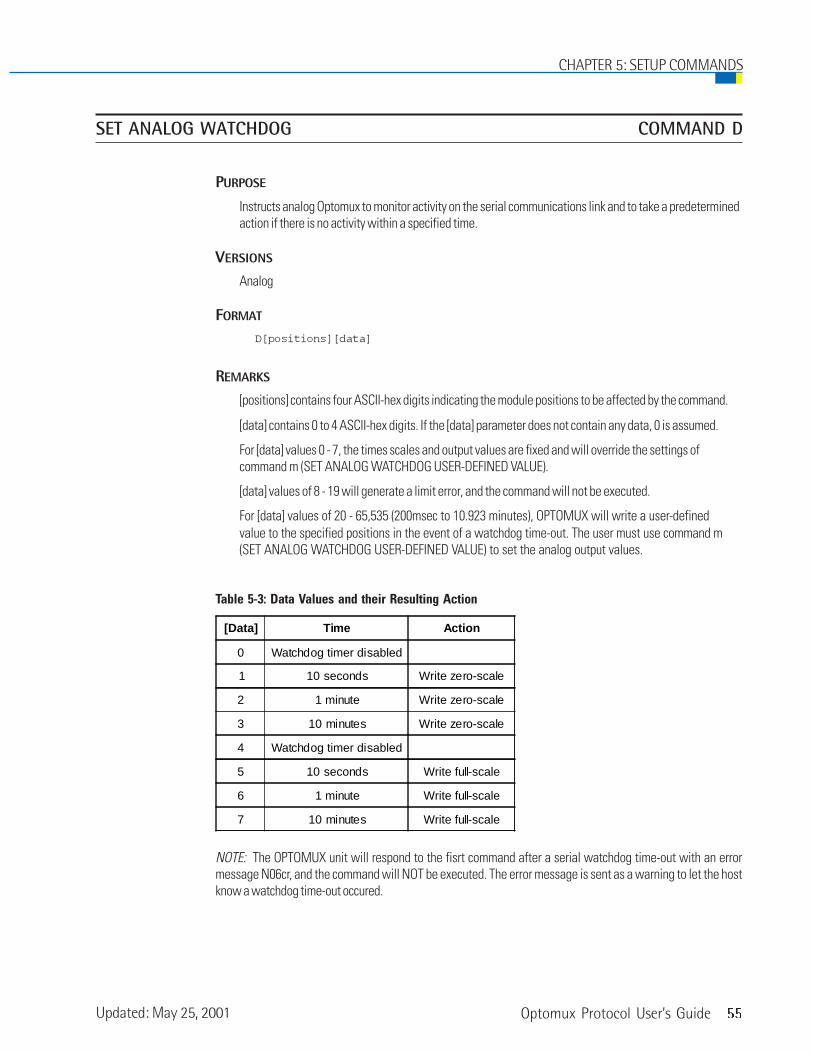
Optomux Protocol User’s Guide 55
SET ANALOG WATCHDOG COMMAND D
PURPOSE
Instructs analog Optomux to monitor activity on the serial communications link and to take a predeterminedaction if there is no activity within a specified time.
VERSIONS
Analog
FORMAT
D[positions][data]
REMARKS
[positions] contains four ASCII-hex digits indicating the module positions to be affected by the command.
[data] contains 0 to 4 ASCII-hex digits. If the [data] parameter does not contain any data, 0 is assumed.
For [data] values 0 - 7, the times scales and output values are fixed and will override the settings ofcommand m (SET ANALOG WATCHDOG USER-DEFINED VALUE).
[data] values of 8 - 19 will generate a limit error, and the command will not be executed.
For [data] values of 20 - 65,535 (200msec to 10.923 minutes), OPTOMUX will write a user-definedvalue to the specified positions in the event of a watchdog time-out. The user must use command m(SET ANALOG WATCHDOG USER-DEFINED VALUE) to set the analog output values.
Table 5-3: Data Values and their Resulting Action
NOTE: The OPTOMUX unit will respond to the fisrt command after a serial watchdog time-out with an errormessage N06cr, and the command will NOT be executed. The error message is sent as a warning to let the hostknow a watchdog time-out occured.
[Data] Time Action
0 Watchdog timer disabled
1 10 seconds Write zero-scale
2 1 minute Write zero-scale
3 10 minutes Write zero-scale
4 Watchdog timer disabled
5 10 seconds Write full-scale
6 1 minute Write full-scale
7 10 minutes Write full-scale
CHAPTER 5: SETUP COMMANDS
Updated: May 25, 2001

56 Optomux Protocol User’s Guide
EXAMPLE
>1AD000F2BEcr
Instructs Optomux at address 1A to output zero-scale at positions 0, 1, 2, and 3 if there is no activity on theserial line for one minute
CHAPTER 5: SETUP COMMANDS

Optomux Protocol User’s Guide 57
SET PROTOCOL COMMAND E
PURPOSE
Instructs Optomux to use either 2-pass or 4-pass protocol.
VERSIONS
Digital, Analog
FORMAT
E[data]
REMARKS
[data] contains a single ASCII digit 0 or 1 which selects protocol:
0 Two-Pass Protocol1 Four-Pass Protocol
If no protocol is specified, protocol = 0 is assumed. On power-up, protocol is set according to Jumper B10.
EXAMPLE
>9BE1F1cr
Instruct Optomux 9B to use 4-pass protocol
CHAPTER 5: SETUP COMMANDS

58 Optomux Protocol User’s Guide
IDENTIFY OPTOMUX TYPE COMMAND F
PURPOSE
Instructs Optomux to identify itself as either a digital or analog I/O unit.
VERSIONS
Digital, Analog
FORMAT
F
REMARKS
Optomux will respond with a return message containing a 2-digit identification code as follows:
00 = Digital Optomux01 = Analog Optomux
EXAMPLE
>D0FBAcr
Command message sent from host requesting Optomux at address D0 to identify itself
A0161cr
Message returned by Optomux identifying itself as an analog Optomux I/O unit
CHAPTER 5: SETUP COMMANDS

Optomux Protocol User’s Guide 59
SET ENHANCED DIGITAL WATCHDOG COMMAND m
PURPOSE
Instructs digital Optomux to monitor activity on the serial communications link and to take a specified actionif there is no activity within a specified time.
VERSIONS
Digital
FORMAT
m[positions][data]
REMARKS
After this command is issued, if a character is not received within the time specified by [data], Optomux willturn on all outputs corresponding to a 1 and turn off all outputs corresponding to a 0 in the bitmaskspecified by [positions]. All time delay outputs are cancelled and inputs are not affected.
The delay time may be 0 to 4 digits and is set to [data] * 10 milliseconds. Delays of less than 200milliseconds (except 0), will result in a limit error and the command is not executed. A delay time of zerodisables the digital watchdog function. If no delay time is sent, 0 is assumed.
The Optomux unit will respond to the first command after a serial watchdog time-out with a N06cr errorcode message and the command will NOT be executed. This error code is sent as a warning to let the hostknow a watchdog time-out occurred.
EXAMPLE
>ECm0A841F47Dcr
This command message instructs Optomux at address EC to turn on output modules 11, 9, 7, and 2 and turnoff all other output modules if there is no activity on the serial line for 5 seconds. This example assumesthat the positions indicated were previously configured as outputs.
CHAPTER 5: SETUP COMMANDS
60 Optomux Protocol User’s Guide
SET ANALOG WATCHDOG USER-DEFINED VALUE COMMAND m
PURPOSE
Used in conjunction with command D, Set Analog Watchdog, this command sets the data that an analogOptomux will write to the specified output modules upon a serial watchdog time-out.
VERSIONS
Analog
FORMAT
m[positions][data]
REMARKS
[positions}contains four ASCII-hex digits indicating the module positions to be affected by the command.
[data] is set only for output modules that correspond to a 1 in the [positions] bitmask. Three characters ofdata are expected for each output module specified. If enough data is not received (the number of datavalues must equal the number of bits set to 1 in the bitmask), Optomux will respond with a N05cr data fielderror message.
The delay time is set by command D, SET ANALOG WATCHDOG.
The Optomux unit will respond to the first command after a serial watchdog time-out with an errormessage N06cr, and the command will not be executed. This error code is sent as a warning to let the hostknow a watchdog time-out occurred.
EXAMPLE
>AAm0081A20555FAcr
This message instructs Optomux at address AA to output the value A20 at position 7 and a value of 555 tooutput module at position 0 when a serial watchdog time-out occurs.
CHAPTER 5: SETUP COMMANDS
Optomux Protocol User’s Guide 61
SET TIMER RESOLUTION COMMAND n
PURPOSE
This command sets a global timer value for all timing functions on the Optomux digital brain.
VERSIONS
Digital
FORMAT
n[data]
REMARKS
[data] contains two ASCII hex digits indicating the timer resolution. The timing resolution is equal to [data]* 10 milliseconds. If the value in [data] is 0, the timer resolution will be 2.56 seconds.
NOTE: This command is a global command and affects the time base for the entire Optomux brain board. Thiscommand affects the timing resolution for the following commands:
SET TIME DELAYINITIATE SQUARE WAVEHIGH RESOLUTION SQUARE WAVERETRIGGER TIME DELAYGENERATE N PULSESSTART ON PULSESTART OFF PULSEREAD PULSE COMPLETE BITSREAD PULSE DURATION COUNTERSREAD AND CLEAR DURATION COUNTERS
EXAMPLE
>FEn0A6Acr
This example sets the timer resolution of the digital Optomux at address FE to 100 ms.
CHAPTER 5: SETUP COMMANDS

62 Optomux Protocol User’s Guide
SET TEMPERATURE PROBE TYPE COMMAND k
PURPOSE
This command sets the probe type for positions using temperature input modules (thermocouples, ICTDs,and RTDs), so that the READ TEMPERATURE INPUTS command can be used to read the temperaturedirectly.
VERSIONS
Analog
FORMAT
k[positions][data]
REMARKS
[positions] is a field of 4 ASCII-hex digits indicating which positions will be affected by the command.
[data] is a single ASCII-hex character which sets the temperature probe type for all the modulescorresponding to a 1 in the bitmask [positions]. The following table indicates the possible values for[data]:
CHAPTER 5: SETUP COMMANDS
Updated: May 25, 2001

Optomux Protocol User’s Guide 63
Table 5-4: Data Values and their Coresponding Temperature Types
The “SET TEMPERATURE PROBE TYPE” command can be sent multiple times with different values for[positions] and [data] to set a variety of probes on one rack.
EXAMPLE
>DCk40607F3cr
This example shows a command message sent from the host to Optomux at address DC. The message setsthe temperature probe type for modules in positions 14, 6, and 5 to a type S thermocouple.
Data Positions
0 No Temperature Probe
1 ICTD Probe (AD4 Module)
210 Ohm RTD Probe
(AD14T Module)
3100 Ohm RTD Probe
(AD10T Module)
4Type J Thermocouple
(AD5/AD5T)
5Type K Thermocouple
(AD8/AD8T)
6Type R Thermocouple
(AD17T)
7Type S Thermocouple
(AD17T)
8Type T Thermocouple
(AD18T)
9Type E Thermocouple
(AD19T)
A Reserved
B Reserved
C Reserved
D Reserved
E Reserved
F Reserved
CHAPTER 5: SETUP COMMANDS

64 Optomux Protocol User’s Guide
CHAPTER 5: SETUP COMMANDS

Optomux Protocol User’s Guide 65
CONFIGURE POSITIONS COMMAND G
PURPOSE
Identifies the function of positions as either inputs or outputs.
VERSIONS
Digital, Analog
FORMAT
G[positions]
REMARKS
[positions] contains from 0 to 4 ASCII-hex digits. Each digit specifies the configuration of four modulepositions. Positions corresponding to 1 bits are configured as outputs. Positions corresponding to 0 bits areconfigured as inputs. If the [positions] field is not given, a value of FFFF is assumed by Optomux.
0 bit in positions field = Input1 bit in positions field = Outputs
Positions not specified are left unchanged. If the configuration for any relay position is changed, any time-delay, latch, etc. is cleared.
On power-up, all positions are configured as inputs.
EXAMPLE
>00G11336Fcr
Command message sent from host instructing Optomux at address 00 to configure positions 0, 1, 4, 5, 8,and 12 to function as outputs. All other positions will be configured to function as inputs.
>45G2E2cr
This command message instructs the Optomux I/O unit with address 45 to configure positions 0, 2, and 3 tofunction as inputs and position 1 to function as an output. All other positions are unchanged.
I/O Configuration Commands
CHAPTER 6
66 Optomux Protocol User’s Guide
CHAPTER 6: I/O CONFIGURATION COMMANDS
CONFIGURE AS INPUTS COMMAND H
PURPOSE
Configures module positions to function as inputs.
VERSIONS
Digital, Analog
FORMAT
H[positions]
REMARKS
[positions] contains from 0 to 4 ASCII-hex digits. Each digit in the positions field specifies the function offour module positions. Module positions corresponding to 1 bits in the position field are configured tofunction as inputs. All other module positions are left unchanged. If [positions] is not included, Optomuxassumes a value of FFFF.
If this command changes the configuration of any position, any previous waveform, latch, etc., is cleared.
EXAMPLE
>4BH5F3cr
Configure positions 0 and 2 on Optomux 4 as inputs; all other positions are left unchanged.

Optomux Protocol User’s Guide 67
CHAPTER 6: I/O CONFIGURATION COMMANDS
CONFIGURE AS OUTPUTS COMMAND I
PURPOSE
Configures module positions to function as outputs.
VERSIONS
Digital, Analog
FORMAT
I[positions]
NOTE: This command is an uppercase i, NOT a lowercase L.
REMARKS:[positions] contains from 0 to 4 ASCII-hex digits. Each digit in the positions field specifies the function offour module positions. Module positions corresponding to 1 bits in the position field are configured tofunction as outputs. All other module positions are left unchanged. If [positions] is not given, a value of FFFFis assumed by Optomux.
If the configuration of a point is changed by this command, any time delay, latch, etc. is cleared.
EXAMPLE:>4BI5F4cr
Configure positions 0 and 2 on Optomux 4B to function as outputs.

68 Optomux Protocol User’s Guide
READ MODULE CONFIGURATION COMMAND j
PURPOSE
This command returns the current input/output configuration
VERSIONS
Digital, Analog
FORMAT
j
REMARKS
Returns the current configuration for all 16 I/O module positions. Optomux responds by returning amessage that contains four ASCII-hex digits that specify which positions are configured as inputs and whichare configured as outputs. Each digit corresponds to four module positions in the same manner as the digitscontained in a positions field. Module positions corresponding to 1 bits are configured as outputs, andpositions corresponding to 0 bits are configured as inputs.
EXAMPLE
>FFj??cr
Command sent from host to Optomux at address FF hex (255 decimal), requesting the current configurationof all the positions. Notice how a ?? is used for the checksum. The ?? is a wildcard character for use whendebugging.
A0000C0cr
Response from Optomux indicating that all positions are configured as inputs.
CHAPTER 6: I/O CONFIGURATION COMMANDS

Optomux Protocol User’s Guide 69
WRITE OUTPUTS COMMAND J
PURPOSE
Turns output modules ON and OFF.
VERSIONS
Digital
FORMAT
J[positions]
REMARKS
[positions] contains from 0 to 4 ASCII-hex digits. Each digit in the positions field specifies the ON/OFFstatus of four module positions. Module positions corresponding to 1 bits in the position field are turnedON. Module positions corresponding to 0 bits are turned OFF. Time Delays, if set, are implemented uponexecution of this command. Module positions that have been configured to function as inputs are notaffected by this command. If the [positions] field is left out, Optomux will assume a positions bitmask ofFFFF.
EXAMPLE
>00JFFFFC2cr
Turn ON all outputs at Optomux address 00
>45J0E3cr
Turn OFF modules 0, 1, 2, 3 at Optomux address 45; module positions 4-15 are not affected.
Digital Read/Write Commands
CHAPTER 7

70 Optomux Protocol User’s Guide
ACTIVATE OUTPUTS COMMAND K
PURPOSE
Turns ON output modules.
VERSIONS
Digital
FORMAT
K[positions]
REMARKS
[positions] contains from 0 to 4 ASCII-hex digits. Each digit in the positions field specifies the status of fourmodule positions. Module positions corresponding to 1 bits in the position field are turned ON. All othermodule positions are left unchanged. Time delays, if set, are implemented upon execution of this command.Module positions that have been configured to function as inputs are not affected by this command. If the[positions] field is left out, Optomux will assume a positions bitmask of FFFF.
EXAMPLE
>99K55CCADcr
Instructs Optomux at address 99 to activate outputs at positions 2, 3, 6, 7, 8, 10, 12, and 14. All otherpositions are not affected.
CHAPTER 7: DIGITAL READ/WRITE COMMANDS

Optomux Protocol User’s Guide 71
CHAPTER 7: DIGITAL READ/WRITE COMMANDS
DEACTIVATE OUTPUTS COMMAND L
PURPOSE
Turns OFF output modules.
VERSIONS
Digital
FORMAT
L[positions]
REMARKS
[positions] contains from 0 to 4 ASCII-hex digits. Each digit in the positions field specifies the status of fourmodule positions. Module positions corresponding to 1 bits in the position field are turned OFF. All othermodule positions are left unchanged. Time delays, if set, are implemented upon execution of this command.Module positions that have been configured to function as inputs are not affected by this command. If the[positions] field is left out, Optomux will assume a positions bitmask of FFFF.
EXAMPLE
>BCL607cr
This command tells the Optomux at address BC to turn OFF outputs at positions 1 and 2.
>9ALFFFFDEcr
Instruct Optomux at address 9A to turn OFF all outputs (equivalent to WRITE OUTPUTS command with[positions] = “0000”).

72 Optomux Protocol User’s Guide
READ ON/OFF STATUS COMMAND M
PURPOSE
Returns the ON/OFF status of all module positions.
VERSIONS
Digital
FORMAT
M
REMARKS
Returns the current state of all 16 module positions. Optomux responds by returning a message thatcontains four ASCII-hex digits which specify the ON/OFF status of 16 module positions. Each digitcorresponds to four module positions in the same manner as the digits contained in the positions field.Module positions corresponding to 1 bits are in the ON state, and positions corresponding to0 bits are in the OFF state.
EXAMPLE
>FFMD9cr
Command sent from host to Optomux at address FF, requesting the ON/OFF status of all positions.
A0000C0cr
Response from Optomux indicating that all positions are in the OFF state.
A0AC2E6cr
Response from Optomux indicating that positions 1, 6, 7, 9, and 11 are ON, and that all others are OFF.
CHAPTER 7: DIGITAL READ/WRITE COMMANDS

Optomux Protocol User’s Guide 73
SET LATCH EDGES COMMAND N
PURPOSE
Set positions configured as inputs to latch on either ON-to-OFF or OFF-to-ON transitions.
VERSIONS
Digital
FORMAT
N[positions]
REMARKS
[positions] contains from 0 to 4 ASCII-Hex digits. If [positions] is not given, Optomux assumes a positionsbitmask of FFFF. Each digit in the positions field specifies the status of four module positions. Modulepositions corresponding to 1 bits in the positions field are set to latch onON-to-OFF transitions. Module positions corresponding to 0 bits in the positions field are setto latch on OFF-to-ON transitions. All other module positions are left unchanged.
Module positions that have been configured to function as outputs are not affected by this command. Onpower-up, all inputs are set to latch OFF-to-ON.
EXAMPLE
>55NFFFECFcr
This command instructs the Optomux at address 55 to set position 0 to latch on OFF-to-ON transitions, allother positions are set to latch on ON-to-OFF transitions.
Digital Latch Commands
CHAPTER 8
74 Optomux Protocol User’s Guide
SET OFF-TO-ON LATCHES COMMAND O
PURPOSE
Sets positions to latch on OFF-to-ON transitions
VERSIONS
Digital
FORMAT
O[positions]
REMARKS
[positions] contains from 0 to 4 ASCII-hex digits. If [positions] is not given, Optomux assumes a positionsbitmask of FFFF. Each digit in the positions field specifies the status of four module positions. Modulepositions corresponding to 1 bits in the positions field are set to latch onOFF-to-ON transitions. All other module positions are left unchanged. Module positions thathave been configured to function as outputs are not affected by this command. On power-up,all inputs are set to latch OFF-to-ON.
EXAMPLE
>FFOC000AEcr
This command configures positions 14 and 15 at Optomux address FF to latch on OFF-to-ON transitions; allother positions are not affected.
CHAPTER 8: DIGITAL LATCH COMMANDS

Optomux Protocol User’s Guide 75
CHAPTER 8: DIGITAL LATCH COMMANDS
SET ON-TO-OFF LATCHES COMMAND P
PURPOSE
Sets positions to latch on ON-to-OFF transitions
VERSIONS
Digital
FORMAT
P[positions]
REMARKS
[positions] contains from 0 to 4 ASCII-hex digits. If [positions] is not given, Optomux assumes a positionsbitmask of FFFF. Each digit in the positions field specifies the status of four module positions. Modulepositions corresponding to 1 bits in the positions field are set to latch onON-to-OFF transitions. All other module positions are left unchanged. Module positions thathave been configured to function as outputs are not affected by this command. On power-up,all inputs are set to latch OFF-to-ON.
EXAMPLE
>FFPC000AFcr
This command instructs Optomux at address FF to set positions 14 and 15 to latch on ON-to-OFF transitions;all other positions are not affected.

76 Optomux Protocol User’s Guide
READ LATCHES COMMAND Q
PURPOSE
Returns data indicating which of the inputs have latched.
VERSIONS
Digital
FORMAT
Q
REMARKS
Returns the current state of all latches. Optomux responds by returning a message that containsfour ASCII-hex digits that specify which module positions have latched (the correct edge has been detectedat that position). Each digit corresponds to four module positions in the same manner as the digitscontained in the positions field. Module positions corresponding to 1 bits have been latched. Bitscorresponding to positions configured as outputs should be ignored. This command has no effect on theOptomux latches so subsequent READ LATCHES commands will return consistent results.
EXAMPLE
>77QBFcr
Command sent from host computer to read latches on Optomux at address 77.
A8888E0cr
Message returned from Optomux indicating that inputs at positions 15, 11, 7, and 3 have latched.
CHAPTER 8: DIGITAL LATCH COMMANDS

Optomux Protocol User’s Guide 77
READ AND CLEAR LATCHES COMMAND R
PURPOSE
Returns data indicating which of the inputs have latched and then resets the latches for specified inputpositions to the unlatched state.
VERSIONS
Digital
FORMAT
R[positions]
REMARKS
[positions] contains from 0 to 4 ASCII-hex digits. Each digit in the positions field specifies the status of fourmodule positions. Module positions corresponding to 1 bits will have their latches cleared (set to“unlatched”); all other latches are left unchanged. If the positions field is omitted all latches will be cleared.
Optomux responds by returning a message that contains four ASCII-hex digits that specify which modulepositions have latched (the correct edge has been detected at that position). Each digit corresponds to fourmodule positions in the same manner as the digits contained in the positions field. Module positionscorresponding to 1 bits have been latched. Bits corresponding to positions configured as outputs should beignored.
EXAMPLE
>77RB032cr
Command message to read all latches on Optomux at address 77, and to clear latches for positions 4, 5, and7.
A762AE0cr
Response from Optomux indicating that positions 1, 3, 5, 9, 10, 12, 13, and 14 have latched.
CHAPTER 8: DIGITAL LATCH COMMANDS

78 Optomux Protocol User’s Guide
CLEAR LATCHES COMMAND S
PURPOSE
Sets latches for specified input positions to unlatched state.
VERSIONS
Digital
FORMAT
S[positions]
REMARKS
[positions] contains from 0 to 4 ASCII-hex digits. If [positions] is not given, Optomux assumes a positionsbitmask of FFFF. Each digit in the positions field specifies the status of four module positions. Modulepositions corresponding to 1 bits will have their latches cleared (set to “unlatched”); all other latches areleft unchanged. If the positions field is omitted all latcheswill be cleared.
EXAMPLE
>77SC1cr
This command instructs Optomux at address 77 to clear all latches.
>77S1F2cr
Instructs Optomux at address 77 to clear the latch for position 0.
CHAPTER 8: DIGITAL LATCH COMMANDS

Optomux Protocol User’s Guide 79
START/STOP COUNTERS COMMAND T
PURPOSE
Starts and stops counting of OFF-to-ON transitions at specified input positions.
VERSIONS
Digital
FORMAT
T[positions]
REMARKS
[positions] contains from 0 to 4 ASCII-hex digits. If [positions] is not given, Optomux will assumea positions bitmask of FFFF. Each digit in the positions field specifies the status of four module positions.Optomux will start counting OFF-to-ON transitions at module positions correspondingto 1 bits in the positions field. Optomux will stop counting OFF-to-ON transitions at modulepositions corresponding to 0 bits in the positions field. All other positions are left unchanged.
This command has no effect on the stored count and counting can be started or resumed at any time.
The maximum count is 65,535; the counter then resets to 0.
Frequencies up to 400 Hertz with a minimum pulse width of 1.25 milliseconds can be counted.
EXAMPLE
>73T0F34cr
This example instructs Optomux at address 73 to start counting at positions 0, 1, 2, and 3, and to stopcounting at positions 4, 5, 6, and 7. All other positions are left unchanged.
Digital Counting Commands
CHAPTER 9

80 Optomux Protocol User’s Guide
CHAPTER 9: DIGITAL COUNTING COMMANDS
START COUNTERS COMMAND U
PURPOSE
Starts/resumes counting of OFF-to-ON transitions at specified input positions.
VERSIONS
Digital
FORMAT
U[positions]
REMARKS
[positions] contains from 0 to 4 ASCII-hex digits. If [positions] is not given, Optomux will assumea positions bitmask of FFFF. Each digit in the positions field specifies the status of four module positions.Optomux will start counting OFF-to-ON transitions at input positions corresponding to1 bits in the positions field. All other positions are not affected.
This command has no effect on a preexisting count value, if any.
The maximum count is 65,535; the counter then resets to 0.
Frequencies up to 400 Hertz with a minimum pulse width of 1.25 milliseconds can be counted.
EXAMPLE
>EEU3042cr
This command starts counting at positions 4 and 5 on Optomux address EE.

Optomux Protocol User’s Guide 81
STOP COUNTERS COMMAND V
PURPOSE
Stops counting of OFF-to-ON transitions at specified input positions.
VERSIONS
Digital
FORMAT
V[positions]
REMARKS
[positions] contains from 0 to 4 ASCII-hex digits. If [positions] is not given, Optomux will assumea positions bitmask of FFFF. Each digit in the positions field specifies the status of four module positions.Optomux will stop counting OFF-to-ON transitions at input positions corresponding to1 bits in the positions field. All other positions are left unchanged.
This command has no effect on the current value of the counters. Counting can be resumed atany time.
EXAMPLE
>EDV80077cr
This command message stops counting at position 11 on Optomux address ED.
CHAPTER 9: DIGITAL COUNTING COMMANDS

82 Optomux Protocol User’s Guide
READ COUNTERS COMMAND W
PURPOSE
Returns the counter values for the specified input positions.
VERSIONS
Digital
FORMAT
W[positions]
REMARKS
[positions] contains from 0 to 4 ASCII-hex digits. Each digit in the positions field specifies the status of fourmodule positions. Optomux will return the counter values for the input positions corresponding to 1 bits inthe positions field. Values are returned as four ASCII-hex digits which represent a 16-bit value (0 to 65,535decimal). Counter values are returned in sequence from the highest to lowest module position. Attempts toread an output will result in a string of four question marks “????” being returned for that position. Thiscommand has no effect on the current value of the counters. If the positions field is omitted from thecommand message a position field of FFFF is assumed (all counters are read).
CHAPTER 9: DIGITAL COUNTING COMMANDS

Optomux Protocol User’s Guide 83
CHAPTER 9: DIGITAL COUNTING COMMANDS
EXAMPLE
>23W6F2cr
Command message sent from host to Optomux at address 23 to read counters for module positions1 and 2.
AB00000089Acr
Message returned by Optomux. Counter value is B000 for position 2 (45,056 decimal) and 0008(8 decimal) for position 1.
>23W5555Bcr
Command message sent from host computer to Optomux. Read counters 0, 2, 4, 6, 8, and 10 atAddress 23.
A123405671111????ABCD000127cr
The return message can be interpreted as follows:
Position Hex Data Decimal Value
0 0001 1
2 ABCD 43,981
4 ???? position 4 is an output
6 1111 4,369
8 0567 1,383
10 1234 4,660

84 Optomux Protocol User’s Guide
READ AND CLEAR COUNTERS COMMAND X
PURPOSE
Returns the counter values for the specified positions and then sets the counters for those positionsto 0.
VERSIONS
Digital
FORMAT
X[positions]
REMARKS
This command performs the READ COUNTERS function and then clears the counters for the positions thatwere read. [positions] contains from 0 to 4 ASCII-hex digits. Each digit in the positions field specifies thestatus of four module positions. Optomux will return the counter values for the module positionscorresponding to 1 bits in the positions field and then clear the counters for those positions. Values arereturned as four ASCII-hex digits which represent a 16-bit value (0 to 65,535 decimal). Counter values arereturned in sequence from the highest to lowest module position. Attempts to read an output will result ina string of four question marks (????) being returned for that position. If the positions field is omitted fromthe command message a position field of FFFF is assumed(all counters are read and cleared).
EXAMPLE
>A8X80069cr
This message instructs Optomux at address A8 to return a counter value for position 11, then clear thecounter to 0.
>A0F00D6cr
This response from Optomux shows the counter value of position 11 to be F00 hex or 3,840 decimal.
CHAPTER 9: DIGITAL COUNTING COMMANDS
Optomux Protocol User’s Guide 85
CLEAR COUNTERS COMMAND Y
PURPOSE
Resets counters for specified input positions.
VERSIONS
Digital
FORMAT
Y[positions]
REMARKS
[positions] contains from 0 to 4 ASCII-hex digits. Each digit in the positions field specifies the status of fourmodule positions. Optomux will clear the counter values for the input positions corresponding to 1 bits inthe positions field. All other positions are left unchanged. If the positions field is omitted from thecommand message a position field of FFFF is assumed (all counters are cleared).
EXAMPLE
>A8Y8006Acr
This command clears the counters for position 11 at Optomux address A8.
CHAPTER 9: DIGITAL COUNTING COMMANDS

86 Optomux Protocol User’s Guide
CHAPTER 9: DIGITAL COUNTING COMMANDS
Optomux Protocol User’s Guide 87
SET TIME DELAY COMMAND Z
PURPOSE
Sets specified output positions to be used in a pulsed or delayed mode.
VERSIONS
Digital
FORMAT
Z[positions][modifier][data]
REMARKS
[positions] four ASCII-hex digits which specify the module positions to be affected. Module positionscorresponding to 1 bits in the positions field will be used in the selected delayed or pulsed mode.
[data] contains from 1 to 4 ASCII-Hex digits representing the length of the delay. The actual delay time isequal to
desired time = [data] * TRS * 10 mSec. or
[data] = desired time/(TRS * 10 mSec.)
Where TRS is the Timer Resolution Setting as set by the “Set Timer Resolution Command.”The default for TRS is 1.
NOTE: A value of 0 for [data] is equivalent to a value of FFFF (65,535).
[modifier] contains a single ASCII character which specifies the type of delay to be used. Valid delay typesare:
Digital Time Delay/Pulse Commands
CHAPTER 10

88 Optomux Protocol User’s Guide
CHAPTER 10: DIGITAL TIME DELAY/PULSE COMMANDS
Table 10-1: Values for “Modifier” Parameter
The timer resolution is set by the “SET TIMER RESOLUTION” command.
With type L and M modifiers, the square wave will continue to be output until the delay type for the outputis changed or turned off. The “WRITE OUTPUTS,” “ACTIVATE OUTPUTS,” and “DEACTIVATE OUTPUTS”commands will have NO EFFECT when using the type L and M modifiers.
EXAMPLE
All examples assume a TRS value of 1 (10 mSec).
>89ZCI66C3cr
Set module positions 2 and 3 at Optomux address 89 for delay type I with a pulse length of 1.02 seconds.
>24Z1000GC8cr
Turn off existing delay at Optomux address 24, module position 12.
>10Z1111K3E87Acr
At Optomux address 10, set positions 12, 8, 4, and 0 for a type K delay of 10 seconds.
>11Z66L015842cr
At address 11, set positions 6, 5, 2, and 1 for a square wave — ON 2.56 seconds, OFF 3.75 minutes.
>1EZ42M041F5Ecr
At address 1E, set positions 1 and 6 for a high resolution square wave; ON for 40 mSec, and OFF for310 mSec.
[modifier] Description of Delay Type
G Normal Operation - turn off existing delay (when using thismodifier [data] may be omitted from the command message).
H When instructed to go from OFF to ON, turn ON for desiredtime, then turn OFF
I When instructed to go from OFF to ON, stay OFF for desiredtime, then turn ON
J When instructed to go from ON to OFF, turn OFF for desiredtime, then turn ON
K When instructed to go from ON to OFF, stay ON for desiredtime, then turn OFF
L
Initiate a continuous square wave with "ON" and "OFF" timescomputed as follows:"ON" time = 2.56 seconds * TRS * the first two digits in thedata field (leftmost characters"OFF" time = 2.56 x * TRS * the last two digits in the data field
M
Initiate a continuous high resolution square wave with "ON"and "OFF" times computed as follows:"ON" time = TRS * the first two digits in the data field (leftmostcharacters)"OFF" time = TRS * the last two digits in the data field

Optomux Protocol User’s Guide 89
CHAPTER 10: DIGITAL TIME DELAY/PULSE COMMANDS
RETRIGGER TIME DELAY COMMAND h
PURPOSE
Restarts or triggers an existing time delay.
VERSIONS
Digital
FORMAT
h[positions]
REMARKS
This command overrides an existing time delayed output by setting the time delay counter to the originaltime delay value, then retriggering the time delay if it was currently active. The original time delay was thevalue set by the “Set Time Delay” command. This command can be used to extend the time-out period of anoutput (as in a watchdog circuit).
Since the “SET TIME DELAY” command cancels a time delay that is active, the “RETRIGGER TIME DELAY”command can be used after a “SET TIME DELAY” command to dynamically change the time-out period.
This command does not affect square wave generation. If no [positions] bitmask is sent, an FFFF(all positions) is assumed.
EXAMPLE
>2Eh2041cr
This command instructs Optomux at address 2E to retrigger a time delay on module position 5.

90 Optomux Protocol User’s Guide
GENERATE N PULSES COMMAND i
PURPOSE
This command instructs Optomux to output a specified number of pulses.
VERSIONS
Digital
FORMAT
i[positions][modifier][data]
REMARKS
The bitmask in [positions] must consist of four ASCII-hex digits and represents the output modules to beaffected. The quantity in [modifier] must be two digits (00 to FF) and represents one-half of the period forthe pulses in increments of the timer resolution setting. All pulses have a 50 percent duty cycle. The timerresolution is set using the “SET TIMER RESOLUTION” command. A time of 0 will cancel any time delay orpulse stream currently being generated by the specified output. Sending this command when a pulse trainis already active, will cause the pulse train to be retriggered with the latest values.
The quantity specified in the [data] field can be from 0 to 4 ASCII-hex digits (0 to FFFF) and represents thenumber of pulses to be output. A 0 in this field will generate 65,536 pulses.
EXAMPLE
>CCi0040320064E2cr
This example instructs Optomux at address CC to output 100 pulses at position 6. Assuming the TimerResolution Setting (TRS) is 1 (10 mSec.), the pulses will have a period of 1 second (500 mSec. OFF, 500mSec. ON).
CHAPTER 10: DIGITAL TIME DELAY/PULSE COMMANDS

Optomux Protocol User’s Guide 91
START ON PULSE COMMAND k
PURPOSE
Turns on all specified outputs for a specific length of time.
VERSIONS
Digital
FORMAT
k[positions][data]
REMARKS
[positions] must contain four ASCII-hex digits representing the bitmask for the outputs to be pulsed.Positions corresponding to 1 bits will activate a pulse for the duration specified by the value in the [data]field. The quantity in the [data] field represents the period of the “ON” pulse in increments of the timerresolution. The timer resolution is set using the “SET TIMER RESOLUTION” command. [data] may be from 0to 4 ASCII-hex characters. If a zero is specified, the command does nothing. If no [data] value is given, azero is assumed. This function is retriggerable, therefore, it can be used as a watchdog circuit bycontinuously sending this command at a rate faster than the pulse length. To cancel the pulse, set [data] toa 1, and the pulse will turn off and the outputs will be deactivated within one timer increment.
EXAMPLE
>BBk000514??cr
This command configures positions 2 and 0 of the Optomux at address BB to generate an “ON” pulse for aduration of 20 times the timer resolution setting (TRS). All other positions are not affected.
CHAPTER 10: DIGITAL TIME DELAY/PULSE COMMANDS

92 Optomux Protocol User’s Guide
START OFF PULSE COMMAND l
PURPOSE
Turns off all specified outputs for a specific length of time.
VERSIONS
Digital
FORMAT
l[positions][data]
NOTE: This command letter is a lowercase L, NOT an uppercase i.
REMARKS
[positions] must contain four ASCII-hex digits representing the bitmask for the outputs to be pulsed.Positions corresponding to 1 bits will deactivate a pulse for the duration specified by the value in the [data]field. The quantity in the [data] field represents the period of the “OFF” pulse in increments of the timerresolution. The timer resolution is set using the “SET TIMER RESOLUTION” command. [data] may be from 0to 4 ASCII-hex characters. If a zero is specified, the command does nothing. If no [data] value is given, azero is assumed. This function is retriggerable, therefore, it can be used as a watchdog circuit bycontinuously sending this command at a rate faster than the pulse length. To cancel the pulse, set [data] toa 1, and the pulse will turn off and the outputs will be activated within one timer increment.
EXAMPLE
>44l000106??cr
This command configures position 0 of the Optomux at address 44 to generate an “OFF” pulse for aduration of six times the timer resolution setting (TRS). All other positions are not affected.
CHAPTER 10: DIGITAL TIME DELAY/PULSE COMMANDS

Optomux Protocol User’s Guide 93
SET PULSE TRIGGER POLARITY COMMAND a
PURPOSE
Instructs Optomux to measure ON and OFF pulses.
VERSIONS
Digital
FORMAT
a[positions]
REMARKS
[positions] contains from 0 to 4 ASCII-hex digits. Each digit in the positions field specifies the desired pulsetrigger polarity of four module positions. If [positions] is omitted, Optomux assumes a value of FFFF.Positions corresponding to 1 bits are set to measure ON duration, while positions corresponding to 0 bitsare set to measure OFF duration.
Optomux will measure the duration of the first pulse of the appropriate level and store the result to berecalled by the host. As soon as Optomux has measured a complete pulse for any position, a “pulsecomplete bit” is set to indicate that an entire pulse has been measured. The host computer can read the“pulse complete bits” to determine whether Optomux has finished the measurement process, and can thenread the values of the pulse duration counters, if any.
Maximum pulse duration is “FFFF” (65,535) * TRS. where TRS is the Timer Resolution Setting set by the“SET TIMER RESOLUTION” command.
This command does not clear preexisting duration counter values or pulse complete bits. If a positions“pulse complete bit” has been previously set, no measurements are made until that positions’ “pulsecomplete bit” and duration counter are cleared by either the CLEAR DURATION COUNTERS command orthe READ AND CLEAR DURATION COUNTER command.
EXAMPLE
>88a506cr
Instruct Optomux at address 88 to configure positions 2 and 0 to measure “ON” pulses; positions 1 and 3 tomeasure “OFF” pulses; and leave all other positions unchanged.
Digital Pulse DurationMeasurement Commands
CHAPTER 11

94 Optomux Protocol User’s Guide
TRIGGER ON POSITIVE PULSE COMMAND b
PURPOSE
Sets the specified positions to measure the duration of positive (ON) pulses.
VERSIONS
Digital
FORMAT
b[positions]
REMARKS
[positions] contains from 0 to 4 ASCII-hex digits. Each digit in the positions field specifies the status of fourmodule positions. If [positions] is omitted, Optomux assumes a value of FFFF. Positions corresponding to 1bits are set to measure ON duration. All other positions are left unchanged.
Optomux will measure the duration of the first positive pulse and store the result to be recalled by the host.As soon as Optomux has measured a complete pulse for a given position, a “pulse complete bit” is set toindicate that an entire pulse has been measured. The host computer can read the “pulse complete bits” todetermine whether Optomux has finished the measurement process and can then read the values of thepulse duration counters, if any.
Maximum pulse duration is “FFFF” (65,535) * TRS. where TRS is the Timer Resolution Setting set by the“SET TIMER RESOLUTION” command.
This command does not clear preexisting duration counter values or pulse complete bits. If a positions“pulse complete bit” has been previously set, no measurements are made until that positions’ “pulsecomplete bit” and duration counter are cleared by either the CLEAR DURATION COUNTERS command orthe READ AND CLEAR DURATION COUNTER command.
EXAMPLE
>BBb51Bcr
This command configures positions 2 and 0 to measure “ON” pulses at Optomux address BB. All otherpositions are not affected.
CHAPTER 11: DIGITAL PULSE DURATION MEASUREMENT COMMANDS

Optomux Protocol User’s Guide 95
CHAPTER 11: DIGITAL PULSE DURATION MEASUREMENT COMMANDS
TRIGGER ON NEGATIVE PULSE COMMAND c
PURPOSE
Sets the specified positions to measure the duration of negative (OFF) pulses.
VERSIONS
Digital
FORMAT
c[positions]
REMARKS
[positions] contains from 0 to 4 ASCII-hex digits. Each digit in the positions field specifies the status of fourmodule positions. If [positions] is omitted, Optomux assumes a value of FFFF. Positions corresponding to 1bits are set to measure OFF duration. All other positions are unchanged.
Optomux will measure the duration of the first negative pulse, and store the result to be recalled by thehost. As soon as Optomux has measured a complete pulse for a given position, a “pulse complete bit” is setto indicate that an entire pulse has been measured. The host computer can read the “pulse complete bits”to determine whether Optomux has finished the measurement process and can then read the values of thepulse duration counters, if any.
Maximum pulse duration is “FFFF” (65,535) * TRS. where TRS is the Timer Resolution Setting set by the“SET TIMER RESOLUTION” command.
This command does not clear preexisting duration counter values, or pulse complete bits. If a positions’pulse complete bit has been previously set, no measurements are made until that “pulse complete bit” iscleared by either the CLEAR DURATION COUNTERS or READ AND CLEAR DURATION COUNTERScommand.
EXAMPLE
>BBc51Ccr
This command configures positions 2 and 0 to measure “OFF” pulses at Optomux address BB.All other positions are not affected.

96 Optomux Protocol User’s Guide
READ PULSE COMPLETE BITS COMMAND d
PURPOSE
Allows the host computer to determine which positions have completed the pulse duration measurementperiod.
VERSIONS
Digital
FORMAT
d
REMARKS
Optomux responds to this command with a return message containing four ASCII-hex digits. Each of thesedigits represents the status of four positions. Positions corresponding to 1 bits have completed a pulse ofthe correct level. No further measurements can be made at these positions until the pulse complete bits arereset using either the READ AND CLEAR DURATION COUNTERS or the CLEAR DURATION COUNTERScommand.
EXAMPLE
Assume that positions 0–7 have been configured to function as outputs.
>76dD1cr
Message sent from host requesting the pulse complete bits from Optomux address 76.
A1100C2cr
Return message from Optomux indicating the proper level pulse has been measured for positions 12 and 8.
CHAPTER 11: DIGITAL PULSE DURATION MEASUREMENT COMMANDS

Optomux Protocol User’s Guide 97
READ PULSE DURATION COUNTERS COMMAND e
PURPOSE
Returns the pulse duration counter values for the specified positions.
VERSIONS
Digital
FORMAT
e[positions]
REMARKS
[positions] contains from 0 to 4 ASCII-hex digits. The pulse duration counter values will be returned for themodule positions corresponding to 1 bits in the [positions] field. If [positions] is omitted, Optomux assumes avalue of FFFF.
Pulse duration values are returned as 4 ASCII-Hex digits representing a single 16-bit number (0 to 65,535decimal). Values are returned in sequence from the highest to lowest module position. Attempts to read anoutput will result in a string of four question marks “????” being returned for that position.
If the “READ PULSE DURATION” command is used before the pulse has finished, the current duration willbe returned. To verify that a pulse has completed, see the “READ PULSE COMPLETE BITS” command.
The duration of the measured pulse can be calculated as follows:
duration = [returned data] * TRS * 10 mSec.
where TRS is the timer resolution setting as configured by the “Set Timer Resolution” command.
EXAMPLE
>FFe20083cr
Command sent from host requesting the counter value for position 9 on Optomux address FF.
A6090CFcr
Message returned from Optomux indicating that the duration of the pulse measured was 8.24 minutes. Thisexample assumes a TRS value of 2.
6,090 hex = 24,720 decimal24,720 * TRS * 10 mSec. = 8.24 minutes
CHAPTER 11: DIGITAL PULSE DURATION MEASUREMENT COMMANDS

98 Optomux Protocol User’s Guide
READ AND CLEAR DURATION COUNTERS COMMAND f
PURPOSE
Returns pulse duration counters for the specified positions and then clears them to enable measurement ofthe next pulse.
VERSIONS
Digital
FORMAT
f[positions]
REMARKS
Performs READ PULSE DURATION COUNTERS function, then clears the counter and pulse-complete bitsfor the counters that were read. See READ PULSE DURATION COUNTERS.
Pulse duration values are returned as four ASCII-hex digits representing a single 16-bit number (0 to 65,535decimal). Values are returned in sequence from the highest to lowest module position. Attempts to read anoutput will result in a string of four question marks “????” being returned for that position.
If the “READ AND CLEAR DURATION COUNTERS” command is used before the pulse has finished, thecurrent duration will be returned, the counting will stop, and the pulse complete bit will not be set. To verifythat a pulse has completed, see the “READ PULSE COMPLETE BITS” command.
The duration of the measured pulse can be calculated as follows:
duration = [returned data] * TRS * 10 mSec.
Where TRS is the timer resolution setting as configured by the “Set Timer Resolution” command.
EXAMPLE
>01f1F8cr
Command sent from host requesting the counter value for position 0 of Optomux at address 1. The counteris then cleared after reading.
A6090CFcr
Message returned from Optomux indicating that the duration of the pulse measured was 8.24 minutes. Thisexample assumes a TRS value of 2.
6,090 hex = 24,720 decimal24,720 * TRS * 10 mSec. = 8.24 minutes
CHAPTER 11: DIGITAL PULSE DURATION MEASUREMENT COMMANDS

Optomux Protocol User’s Guide 99
CLEAR DURATION COUNTERS COMMAND g
PURPOSE
Clears the duration counters and pulse complete bits for the specified positions to enable measurement ofthe next pulse.
VERSIONS
Digital
FORMAT
g[positions]
REMARKS
[positions] contains from 0 to 4 ASCII-hex digits that specify which positions are to be affected. Positionscorresponding to 1 bits will have their duration counters and pulse-complete bits cleared. If the positionsfield is omitted all duration counters are cleared.
EXAMPLE
>22g82065cr
Clear duration counters for positions 5 and 11 on the Optomux I/O unit with address 22.
CHAPTER 11: DIGITAL PULSE DURATION MEASUREMENT COMMANDS

100 Optomux Protocol User’s Guide
CHAPTER 11: DIGITAL PULSE DURATION MEASUREMENT COMMANDS

Optomux Protocol User’s Guide 101
WRITE ANALOG OUTPUTS COMMAND J
PURPOSE
Instructs Optomux to output the 12-bit value specified to all positions represented by a 1 in the positionsfield.
FORMAT
J[positions][data]
REMARKS
[positions] is four ASCII-hex characters. All four characters must be present, even if the B2 brain board isconnected to a 4-point analog rack (P4AH).
[data] contains a 12-bit ASCII-hex value to be written to each position identified by a 1-bit in the [positions]field. Values range from 000h (0 decimal) to FFFh (4,095 decimal).
EXAMPLE
Assume Optomux at address FF has DA4 (0-5 V) output modules in positions 0-3. We want to set positions1 and 3 to 1.25 volts.
(1.25 V-0 V)/5 V * 4095 = 1024 decimal = 400 Hex
The command becomes:
>FFJ000A4003Bcr
Analog Read/Write Commands
CHAPTER 12
102 Optomux Protocol User’s Guide
CHAPTER 12: ANALOG READ/WRITE COMMANDS
UPDATE ANALOG OUTPUTS COMMAND S
PURPOSE
Used to write values to one or more analog outputs.
FORMAT
S[positions][data]
REMARKS
[positions] contains four ASCII-hex digits indicating which output positions are to be affected by thecommand. Output module positions corresponding to 1 bits in the positions field will have a value from thedata field written to them.
[data] contains three ASCII-hex digits for each module position specified in the positions field. The 12-bitvalues are placed in the data field in order starting with the highest numbered module position and endingwith the lowest numbered module position. Optomux will respond with a data field error if the commanddoes not include three digits of data for each bit specified in the positions field.
Attempts to write to module positions that have been configured to function as inputs will be ignored.
EXAMPLE
>D0S0224FFF0C01F0ABcr
Instruct Optomux at address D0 to write the value 1F0 to position 2, 0C0 to position 5, and FFF to position 9.

Optomux Protocol User’s Guide 103
READ ANALOG OUTPUTS COMMAND K
PURPOSE
Returns a 12-bit value for each output identified by a 1-bit in the positions field.
FORMAT
K[positions]
REMARKS
[positions] contains 1-4 ASCII-Hex digits indicating which output positions are to be affected by thecommand. A zero value is assumed for leading positions that are omitted. Output module positionscorresponding to 1 bits in the positions field will be read.
Returns three ASCII-hex characters for each position read. Returns “???” if the requested position isconfigured as an input. Since only three characters are returned for each position, do not subtract the offsetof 1,000 hex from the value.
EXAMPLE
Positions 0–7 configured as inputs; Address 86.
>86K1004Acr
This command instructs Optomux to return the current value of position 8.
AB2EB9cr
This is the response if position 8 had a hex value of B2E.
NOTE: [positions] only contains three characters; a 0 value is assumed for leading positions which are omittedwithin the [positions] field. >86K01007Acr is a functionally identical command.
The following command requests the values for positions 7, 8, and 9:
>86K38054cr
A response of:
A000BE2???06cr
indicates that position 9 is an output with a value of 000 Hex, position 8 is an output with a value of BE2hex, and position 7 is configured as an input.
CHAPTER 12: ANALOG READ/WRITE COMMANDS

104 Optomux Protocol User’s Guide
READ ANALOG INPUTS COMMAND L
PURPOSE
Returns the value of each input identified by a 1-bit in the positions field.
FORMAT
L[positions]
REMARKS
Returns four ASCII-hex characters for each position read. Returns “????” if the requested position isconfigured as an output.
The normal range of values for inputs is 1,000h to 1FFFh. If the most significant character is any characterother than 1, it is an indication of over/under range. 0 = under range; >1 = over range
EXAMPLE
>90L5EAcr
This message reads the values of positions 0 and 2 from an Optomux at address 90 hex.
A1000188889cr
This response from Optomux indicates a value of 1,000 hex for position 2 and a value of 1,888 hex forposition 0. Both values are valid readings in the range of 1,000 to 1FFF hex.
The next example shows what happens when a position read is configured as an output.
If the values for positions 10, 8, and 0 are requested with the following command message:
>90L5014Bcr
And positions 8 and 10 were configured as outputs, Optomux would return a response like the following:
A????????1FEEF9cr
Where position 10 is an output, position 8 is an output, and position 0 = 1FEE (a valid value).
If an output module is placed in a position that is configured as an input, and that value is requested,Optomux will return 0000. A value of 0000 will result in a decimal value of -4,096 after the 1,000 hex offsetis subtracted.
CHAPTER 12: ANALOG READ/WRITE COMMANDS

Optomux Protocol User’s Guide 105
READ AND AVERAGE INPUTS COMMAND M
PURPOSE
Instructs Optomux to average the value of a single position over a specified number of samples and then toreturn the result.
FORMAT
M[position][data]
REMARKS
[position] is a single ASCII-hex character representing the module position affected (0 to F).
[data] is two ASCII-hex digits representing the desired number of samples 01-FF hex (1-255 decimal).
Averaging is done using a continuous running average with a sample rate of 100 milliseconds. After thenumber of samples has been reached, the value is returned to the host. The following equation shows howthe average is calculated:
AVERAGE = ((N-1) (OLD AVERAGE) + (NEW READING))/N
NOTE: This command only returns a response when it is done averaging. Therefore, if [data] is very large, there maybe a long delay before you receive an acknowledgment message. Since this delay essentially ties up the whole busfor a period of time, it is recommended that you use the START INPUT AVERAGING, READ AVERAGE COMPLETEBITS, and READ INPUT AVERAGE DATA commands instead.
EXAMPLE
>03M70A58cr
Return the average of 10 samples of position 7 on Optomux at address 03.
CHAPTER 12: ANALOG READ/WRITE COMMANDS

106 Optomux Protocol User’s Guide
START INPUT AVERAGING COMMAND T
PURPOSE
Instructs Optomux to start averaging the value of input positions over a specified number of samples.
FORMAT
T[positions][data]
REMARKS
[positions] contains four ASCII-hex digits indicating which input positions are to be affected by thecommand. Optomux will begin averaging input module positions corresponding to 1 bits in the positionsfield. All other positions will be unaffected.
[data] contains from 0 to 4 ASCII-hex digits specifying the number of consecutive readings to be averaged.If no data field is present, 0 samples will be averaged. The sample rate is 100 milliseconds. This commandis used in conjunction with the “READ AVERAGE COMPLETE BITS,”and the “READ INPUT AVERAGE DATA” commands.
Averaging is done using a continuous running average with a sample rate of 100 milliseconds. The numberof samples to average is set with the START INPUT AVERAGE command. The READ AVERAGE COMPLETEBITS command indicates when the number of samples has been reached. The following equation showshow the average is calculated:
AVERAGE = ((N-1) (OLD AVERAGE) + (NEW READING))/N
This equation still applies, even after N has reached its limit, but keep in mind that N will retain the valueof the limit as new readings are calculated.
EXAMPLE
>1AT04181F0Acr
Instruct Optomux at address 1A to start calculating the average of 1F samples for positions 3, 4, and 10.
CHAPTER 12: ANALOG READ/WRITE COMMANDS

Optomux Protocol User’s Guide 107
READ AVERAGE COMPLETE BITS COMMAND i
PURPOSE
Allows the host to determine which positions have completed averaging.
FORMAT
i
REMARKS
Optomux responds by returning a message that contains four ASCII-hex digits which specify the complete/incomplete status of the averaging process for all 16 module positions. Optomux has completed averagingthe desired number of samples for module positions corresponding to 1 bits. Averaging has not beencompleted for positions corresponding to zero bits. Bits corresponding to positions that have beenconfigured as outputs or to positions that Optomux has not been instructed to average values for should beignored.
EXAMPLE
Assume that Start Input Averaging commands have been sent instructing Optomux start averaging atposition 9, 10, and 11.
>A1iDBcr
Instruct Optomux at address A1 to return average complete bits.
A0A00D1cr
Response from Optomux indicating that averaging has been completed for positions 9 and 11. Optomux hasnot completed averaging position 10.
CHAPTER 12: ANALOG READ/WRITE COMMANDS

108 Optomux Protocol User’s Guide
READ INPUT AVERAGE DATA COMMAND U
PURPOSE
Instructs Optomux to return the results of averaging at specified input positions initiated by theStart input averaging command.
FORMAT
U[positions]
REMARKS
[positions] contains from 0 to 4 ASCII-hex digits specifying the input positions that are to return averageddata. Optomux will return values for module positions corresponding to 1 bits in the positions field. If[positions] is omitted, Optomux will assume a value of FFFF. If Optomux has not completed averaging, thecurrent value of the average will be returned. The READ AVERAGE COMPLETE BITS command provides ameans of determining when averaging is complete.
Four ASCII-hex digits are returned for each position specified in the positions field. Values are returned insequence from the highest to lowest module position. Attempts to read the average of an output will resultin four question marks ???? being returned.
Averaging is done using a continuous running average with a sample rate of 100 milliseconds. The numberof samples to average is set with the START INPUT AVERAGE command. The READ AVERAGE COMPLETEBITS command indicates when the number of samples has been reached. The following equation showshow the average is calculated:
AVERAGE = ((N-1) (OLD AVERAGE) + (NEW READING))/N
This equation still applies, even after N has reached its limit, but keep in mind that N will retain the valueof the limit as new readings are calculated.
EXAMPLE
>FFU2447cr
This message instructs Optomux at address FF to return the averages for positions 2 and 5.
A1A0D1F0CD0cr
Response from Optomux indicating the average for position 2 is 1F0C hex and the average for position 5 is1A0D hex.
CHAPTER 12: ANALOG READ/WRITE COMMANDS

Optomux Protocol User’s Guide 109
READ TEMPERATURE INPUTS COMMAND l
PURPOSE
This command instructs Optomux to report the current temperature readings in degrees Celsius for thespecified modules.
VERSIONS
Analog
FORMAT
l[positions]
NOTE: This command letter is a lowercase L, NOT an uppercase i.
REMARKS:[positions] is a bitmask from 0 to 4 ASCII-hex digits representing the bitmask for the module positions. If[positions] is omitted, Optomux assumes a bitmask value of FFFF.
Optomux returns four ASCII-hex characters representing a signed 16-bit number for each channelcorresponding to a 1 in the [positions] bitmask. The first three characters represent whole degrees Celsiuswhile the last character represents the fractional part (sixteenths – remember it’s hex) of degrees Celsius.In other words, the data returned is 16 times the temperature in degrees Celsius.
Optomux returns ???? for channels which are outputs or have not had a temperature probe type set.
Channels which read below the scale of the probe type which is set, will return a -273º C.
Channels which read above the scale for the probe type which is set, will return a 2,047º C.
EXAMPLE
>FFl0A00C9cr
This command instructs Optomux to return the temperature values for inputs at positions 9 and 11.
CHAPTER 12: ANALOG READ/WRITE COMMANDS

110 Optomux Protocol User’s Guide
This example assumes that the “SET TEMPERATURE PROBE TYPE” command was used previously forpositions 9 and 11.
If the response from Optomux is as follows:
A08A8046BBDcr
This indicates that position 11 has a value of 08A8 hex and position 9 has a value of 046B hex. Convertingthe hex values to decimal, we get position 11 equal to 2,216, and position 9 equal to 1,131. Remember,these returned values are actually 16 times greater than the actual temperature, therefore we must dividethese values by 16.
Position 11 Temperature = 2,216/16 = 138.5º CPosition 9 Temperature = 1,131/16 = 70.68º C
In the next example, the following command is sent:
>FFl8000C0cr
to read the temperature value from position 15. If the response is:
AF956EAcr
then the value for position 15 is F956. You will notice that the sign bit is set, therefore this value is anegative number. Converting the signed value of F956 to decimal results in a value of -1,705. Dividing -1,705 by 16 results in a temperature of -106.56º C.
CHAPTER 12: ANALOG READ/WRITE COMMANDS

Optomux Protocol User’s Guide 111
READ AVERAGE TEMPERATURE INPUTS COMMAND o
PURPOSE
This command instructs Optomux to report the average temperature readings in degrees Celsius for thespecified modules.
VERSIONS
Analog
FORMAT
o[positions]
REMARKS
[positions] is a bitmask from 0 to 4 ASCII-hex digits representing the bitmask for the module positions. If[positions] is omitted, Optomux assumes a bitmask value of FFFF.
Optomux returns four ASCII-hex characters representing a signed 16-bit number for each channelcorresponding to a 1 in the [positions] bitmask. The first three characters represent whole degrees Celsiuswhile the last character represents the fractional part (sixteenths – remember it’s hex) of degrees Celsius.In other words, the data returned is 16 times the temperature in degrees Celsius.
Optomux returns ???? for channels that are outputs or have not had a temperature probe type set.
Averaging must have been previously initiated with the Start Input Averaging command T.
Channels that read below the scale of the probe type which is set will return a -273º C.
Channels that read above the scale for the probe type which is set will return a 2047º C.
EXAMPLE
>FFo0A00CCcr
This command instructs Optomux to return the temperature values for inputs at positions 9 and 11.
CHAPTER 12: ANALOG READ/WRITE COMMANDS

112 Optomux Protocol User’s Guide
This example assumes that the “SET TEMPERATURE PROBE TYPE” and “START INPUT AVERAGING”commands were previously used for positions 9 and 11.
If the response from Optomux is as follows:
A08A8046BBDcr
This indicates that position 11 has a value of 08A8 hex and position 9 has a value of 046B hex. Convertingthe hex values to decimal, we get position 11 equal to 2,216, and position 9 equal to 1,131. Remember,these returned values are actually 16 times greater than the actual temperature, therefore we must dividethese values by 16.
Position 11 Temperature = 2,216/16 = 138.5º CPosition 9 Temperature = 1,131/16 = 70.68º C
In the next example, the following command is sent:
>FFo8000C3cr
to read the average temperature value from position 15. If the response is:
AF956EAcr
then the value for position 15 is F956. You will notice that the sign bit is set, therefore this value is anegative number. Converting the signed value of F956 to decimal results in a value of -1,705. Dividing -1,705 by 16 results in a temperature of -106.56º C.
CHAPTER 12: ANALOG READ/WRITE COMMANDS

Optomux Protocol User’s Guide 113
SET INPUT RANGE COMMAND N
PURPOSE
Defines an input range (high and low limits) for the specified input positions.
FORMAT
N[positions][data]
REMARKS
All four positions characters must be supplied.
[data] must be six ASCII-hex characters; three representing the high limit (12-bits) followed by threerepresenting the low limit. Latches are set when either the high or low limits are exceeded. See Read Out-Of-Range Latches.
EXAMPLE
>09N0003760710AFcr
For positions 0 and 1 on Optomux at address 09 hex, set the upper limit at 760 hex and the lower limit at710 hex. The defined range of values as read back by the Read Analog Inputs command will be from 1,710to 1,760.
Analog Input Range Commands
CHAPTER 13

114 Optomux Protocol User’s Guide
CHAPTER 13: ANALOG INPUT RANGE COMMANDS
READ OUT-OF-RANGE LATCHES COMMAND O
PURPOSE
Reads the high and low Out-Of-Range latches.
FORMAT
O (Hex 4F)
REMARKS
Response is eight ASCII-hex characters.
The first four characters show the status of the high-limit latches; the remaining four show the low-limitlatches. Positions corresponding to 1 bits in the first 16-bit value have exceeded their high limits. Positionscorresponding to 1 bits in the second 16-bit value have fallen below their low limits.
EXAMPLE
>71OB7cr
Read Out-Of-Range latches at Optomux address 71 Hex.
A0001001062cr
Position 0 has exceeded the high limit since the latches were last cleared, and position 4 has exceeded thelow limit.

Optomux Protocol User’s Guide 115
CHAPTER 13: ANALOG INPUT RANGE COMMANDS
READ AND CLEAR OUT-OF-RANGE LATCHES COMMAND P
PURPOSE
This command performs the Read Out-Of-Range Latches command (all positions), then resets the latchesspecified by the [positions] field.
FORMAT
P[positions]
REMARKS
Although all latches are read, only those corresponding to 1 bits in the [positions] field are reset.If no [positions] field is present, all latches are cleared.
The data portion of the response is eight ASCII-hex characters in the format HHHHLLLL.
The first four characters show the status of the high-limit latches, the remaining four show the low-limitlatches. Positions corresponding to 1 bits in the first 16-bit value have exceeded their high limits. Positionscorresponding to 1 bits in the second 16-bit value have fallen below their low limits.
EXAMPLE
>70P4EBcr
Read Out-Of-Range Latches and reset latch at position 2 at Optomux address 70.
A0001000465cr
Module 0 has exceeded the upper limit, module 2 has exceeded the lower limit; only position 2 will havethe latch reset.

116 Optomux Protocol User’s Guide
CLEAR OUT-OF-RANGE LATCHES COMMAND Q
PURPOSE
Clears Out-Of-Range Latches for specified positions.
FORMAT
Q[positions]
REMARKS
Optomux will clear the Out-Of-Range latches for input positions corresponding to 1 bits in the positionsfield. If no positions field is supplied, all latches are reset.
EXAMPLES
>00Q5E6cr
Clears latches at positions 0 and 2 at Optomux address 00 hex.
>99QC3cr
Clears all latches at Optomux address 99 hex.
CHAPTER 13: ANALOG INPUT RANGE COMMANDS

Optomux Protocol User’s Guide 117
READ LOWEST VALUES COMMAND a
PURPOSE
Instructs Optomux to return the lowest readings for specified input positions.
FORMAT
a[positions]
REMARKS
[positions] contains from 0 to 4 ASCII-hex digits that specify which positions are to be affected by thecommand. If [positions] is omitted, Optomux will assume a bitmask of FFFF. Optomux will return the lowestreading for each position corresponding to 1 bits in the positions field. The reading will be the lowestOptomux has encountered since last receiving a Read And Clear Lowest Values or Clear Lowest Valuescommand. Optomux sets all low values to 3,000 hex (over range) upon power-up.
Four ASCII-hex digits are returned for each position specified in the positions field. Values are returned insequence from the highest to lowest module position.
EXAMPLE
>2Aa4A17Acr
Instructs Optomux at address 2A to return the low values for positions 0, 5, 7, and 10.
A130110010FFA100D59cr
Response from Optomux indicating:
Lowest Value for position 0 = 100DLowest Value for position 5 = 0FFA under rangeLowest Value for position 7 = 1,001Lowest Value for position 10 = 1,301
CHAPTER 13: ANALOG INPUT RANGE COMMANDS

118 Optomux Protocol User’s Guide
CLEAR LOWEST VALUES COMMAND b
PURPOSE
Instructs Optomux to clear the lowest readings for specified input positions.
FORMAT
b[positions]
REMARKS
[positions] contains from 0 to 4 ASCII-hex digits that specify which positions are to be affected by thecommand. If [positions] is omitted, Optomux will assume a bitmask of FFFF. Optomux will clear the lowestreading for each input position corresponding to 1 bits in the positions field by setting each positions lowestvalue to 3,000 hex (extreme over-range). This will allow Optomux to store the lowest value encountered insubsequent readings.
EXAMPLE
>2Ab4A17Bcr
Instructs Optomux at address 2A to clear the lowest values for positions 0, 5, 7, and 10.
CHAPTER 13: ANALOG INPUT RANGE COMMANDS
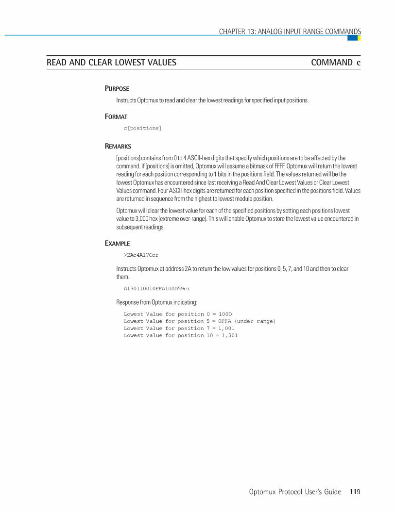
Optomux Protocol User’s Guide 119
READ AND CLEAR LOWEST VALUES COMMAND c
PURPOSE
Instructs Optomux to read and clear the lowest readings for specified input positions.
FORMAT
c[positions]
REMARKS
[positions] contains from 0 to 4 ASCII-hex digits that specify which positions are to be affected by thecommand. If [positions] is omitted, Optomux will assume a bitmask of FFFF. Optomux will return the lowestreading for each position corresponding to 1 bits in the positions field. The values returned will be thelowest Optomux has encountered since last receiving a Read And Clear Lowest Values or Clear LowestValues command. Four ASCII-hex digits are returned for each position specified in the positions field. Valuesare returned in sequence from the highest to lowest module position.
Optomux will clear the lowest value for each of the specified positions by setting each positions lowestvalue to 3,000 hex (extreme over-range). This will enable Optomux to store the lowest value encountered insubsequent readings.
EXAMPLE
>2Ac4A17Ccr
Instructs Optomux at address 2A to return the low values for positions 0, 5, 7, and 10 and then to clearthem.
A130110010FFA100D59cr
Response from Optomux indicating:
Lowest Value for position 0 = 100DLowest Value for position 5 = 0FFA (under-range)Lowest Value for position 7 = 1,001Lowest Value for position 10 = 1,301
CHAPTER 13: ANALOG INPUT RANGE COMMANDS

120 Optomux Protocol User’s Guide
READ PEAK VALUES COMMAND d
PURPOSE
Instructs Optomux to return the peak readings for specified input positions.
FORMAT
d[positions]
REMARKS
[positions] contains from 0 to 4 ASCII-hex digits that specify which positions are to be affected by thecommand. If [positions] is omitted, Optomux will assume a bitmask of FFFF. Optomux will return the peakreading for each position corresponding to 1 bits in the positions field. The value will be the highestOptomux has encountered since last receiving a Read And Clear Peak Values or Clear Peak Valuescommand. Optomux sets all peak values to 0000 Hex (under range) upon power-up.
Four ASCII-hex digits are returned for each position specified in the positions field. Values are returned insequence from the highest to lowest module position.
EXAMPLE:>2AdAA089cr
Instructs Optomux at address 2A to return the peak values for positions 5, 7, 9, and 11.
A1DFF10C11FAC1FB0BAcr
Response from Optomux indicating:
peak Value for position 5 = 1FB0peak Value for position 7 = 1FACpeak Value for position 9 = 10C1peak Value for position 11 = 1DFF
CHAPTER 13: ANALOG INPUT RANGE COMMANDS

Optomux Protocol User’s Guide 121
CLEAR PEAK VALUES COMMAND e
PURPOSE
Instructs Optomux to clear the peak readings for specified input positions.
FORMAT
e[positions]
REMARKS
[positions] contains from 0 to 4 ASCII-hex digits that specify which positions are to be affected by thecommand. If [positions] is omitted, Optomux will assume a bitmask of FFFF. Optomux will clear the peakvalues for each input position corresponding to 1 bits in the positions field by setting the peak value foreach position to 0000 hex (under range). This will allow Optomux to store the highest value encountered insubsequent readings.
EXAMPLE
>2Ae3C07Ecr
Instructs Optomux at address 2A to clear the peak values for positions 6, 7, 8, and 9.
CHAPTER 13: ANALOG INPUT RANGE COMMANDS

122 Optomux Protocol User’s Guide
READ AND CLEAR PEAK VALUES COMMAND f
PURPOSE
Instructs Optomux to read and clear the peak values for specified input positions.
FORMAT
f[positions]
REMARKS
[positions] contains from 0 to 4 ASCII-hex digits that specify which positions are to be affected by thecommand. If [positions] is omitted, Optomux will assume a bitmask of FFFF. Optomux will return the peakvalue for each position corresponding to 1 bits in the positions field. The values returned will be the highestOptomux has encountered since last receiving a Read and Clear Peak Values or Clear Peak Valuescommand. Four ASCII-hex digits are returned for each position specified in the positions field. Values arereturned in sequence from the highest to lowest module position.
Optomux will clear the peak value for each of the specified positions by setting each positions’ peak valueto 0000 hex (under-range). This will enable Optomux to store the highest value encountered in subsequentreadings.
EXAMPLE
>2AfC000ACcr
Instructs Optomux at address 2A to return and then clear the peak values for positions 14 and 15.
A1DFA1C1CE4
Response from Optomux indicating:
Peak Value for position 14 = 1C1CPeak Value for position 15 = 1DFA
CHAPTER 13: ANALOG INPUT RANGE COMMANDS

Optomux Protocol User’s Guide 123
CALCULATE OFFSETS COMMAND g
PURPOSE
Instructs Optomux to calculate and return offsets for specified input positions.
FORMAT
g[positions]
REMARKS
[positions] contains from 0 to 4 ASCII-hex digits. Optomux will return offset values for input positionscorresponding to 1 bits in the positions field. If [positions] is omitted, Optomux will assume a bitmask ofFFFF. The offset values are calculated using the current values of the inputs. Therefore, this command is onlymeaningful when the specified module positions are receiving the value you wish to consider zero scale.
This command is usually used during system installation and calibration when known inputs (zero scale) canbe applied to the modules. The values obtained can be used during Optomux initialization. Optomux can beinstructed to use these offset values by including them in the Set Offsets command.
When utilizing the gain coefficients feature, it is necessary to set offsets for module positions beforesetting the gain coefficients.
Four ASCII-hex digits are returned for each position specified in the positions field. Values are returned insequence from the highest to lowest module position in the same form required by the Set Offsetscommand. Negative offsets are returned as the complement of the number 2.
0001 = +1 OffsetFFFF = -1 Offset
Attempts to calculate the Offset for an output will result in four question marks ???? being returned.
EXAMPLE
>DFgF37cr
Analog Gain/Offset Commands
CHAPTER 14

124 Optomux Protocol User’s Guide
CHAPTER 14: ANALOG GAIN/OFFSET COMMANDS
Instructs Optomux at address DF to calculate and return offset values for positions 0, 1, 2 and 3.
Response from Optomux -
A000AFFFE000100036Ccr
Offset for position 0 = 0003Offset for position 1 = 0001Offset for position 2 = FFFEOffset for position 3 = 000A
>AFg5555C2cr
Instructs Optomux at address AF to calculate and return offset values for positions 0, 2, 4, 6, 8, 10, 12, and14.
Response from Optomux -
A0020FFE9000EFFFD????????001A000D55cr
Offset for position 0 = 000DOffset for position 2 = 001AOffset for position 4 = ????Offset for position 6 = ????Offset for position 8 = FFFDOffset for position 10 = 000EOffset for position 12 = FFE9Offset for position 14 = 0020

Optomux Protocol User’s Guide 125
CHAPTER 14: ANALOG GAIN/OFFSET COMMANDS
SET OFFSETS COMMAND W
PURPOSE
Instructs Optomux to set offsets for specified input positions.
FORMAT
W[positions][data]
REMARKS
[positions] contains four ASCII-hex digits indicating which input positions are to be affected by thecommand. Values from the data field will be used as Offsets for input module positions corresponding to 1bits in the positions field.
[data] contains four ASCII-hex digits for each module position specified in the positions field. The values areplaced in the data field in order starting with the highest numbered module position and ending with thelowest numbered module position. Optomux will respond with a data field error if the command does notinclude four digits of data for each bit specified in the positions field.
Offsets are placed in the [data] field in the same form as they are returned by the Calculate Input Offsetscommand. Negative offsets are represented as the complement of the number 2.
0001 = +1 OffsetFFFF = -1 Offset
Attempts to set Offsets for positions that have been configured to function as outputs will be ignored.
When utilizing the gain coefficients feature, it is necessary to set offsets for module positions beforesetting the gain coefficients.

126 Optomux Protocol User’s Guide
EXAMPLE
>DFW000F000AFFFE0001000323cr
Instructs Optomux at address DF to set the following offsets:
Offset for position 0 = 0003Offset for position 1 = 0001Offset for position 2 = FFFEOffset for position 3 = 000A
>DFW55550020FFE9000EFFFD00000000001A000D92cr
Instructs Optomux at address DF to set the following offset values for positions 0, 2, 4, 6, 8, 10, 12,and 14.
Offset for position 0 = 000DOffset for position 2 = 001AOffset for position 4 = 0000Offset for position 6 = 0000Offset for position 8 = FFFDOffset for position 10 = 000EOffset for position 12 = FFE9Offset for position 14 = 0020
CHAPTER 14: ANALOG GAIN/OFFSET COMMANDS

Optomux Protocol User’s Guide 127
CALCULATE AND SET OFFSETS COMMAND h
PURPOSE
Instructs Optomux to calculate and set offsets for specified input positions. The calculated offsets arereturned to the host.
FORMAT
h[positions]
REMARKS
[positions] contains from 0 to four ASCII-hex digits. Optomux will set and return offset values for inputpositions corresponding to 1 bits in the positions field. If [positions] is omitted, Optomux will assume abitmask of FFFF. The offset values are calculated using the current values of the inputs. Therefore, thiscommand is only meaningful when the specified module positions are receiving the value you wish toconsider zero scale.
This command is usually used during system installation and calibration when known inputs (zero scale) canbe applied to the modules.
Four ASCII-hex digits are returned for each position specified in the positions field. Values are returned insequence from the highest to lowest module position in the same form required by the Set Offsetscommand. Negative offsets are returned as the complement of the number 2.
0001 = +1 OffsetFFFF = -1 Offset
Attempts to calculate and set the offset for an output will result in four question marks ???? being returnedfor that position.
When utilizing the gain coefficients feature, it is necessary to set offsets for module positions beforesetting the gain coefficients.
EXAMPLE
>00h302592cr
CHAPTER 14: ANALOG GAIN/OFFSET COMMANDS

128 Optomux Protocol User’s Guide
Instructs Optomux at address 00 to calculate and set offsets for positions 0, 2, 5, 12, and 13.
A000B0010FFFE000100032Ecr
Response from Optomux indicating that the following offsets have been set:
Offset for position 0 = 0003Offset for position 2 = 0001Offset for position 5 = FFFEOffset for position 12 = 0010Offset for position 13 = 000B
>DFh5555C6cr
Instructs Optomux at address DF to calculate and set offset values for positions 0, 2, 4, 6, 8, 10, 12, and 14.
A0020FFE9000EFFFD????????001A000D55cr
Response from Optomux indicating that the following offset values have been set:
Offset for position 0 = 000DOffset for position 2 = 001AOffset for position 4 = ???? Is an OutputOffset for position 6 = ???? Is an OutputOffset for position 8 = FFFDOffset for position 10 = 000EOffset for position 12 = FFE9Offset for position 14 = 0020
CHAPTER 14: ANALOG GAIN/OFFSET COMMANDS

Optomux Protocol User’s Guide 129
CALCULATE GAIN COEFFICIENTS COMMAND X
PURPOSE
Instructs Optomux to calculate and return gain coefficients for specified input positions.
FORMAT
X[positions]
REMARKS
[positions] contains from 0 to four ASCII-hex digits. Optomux will calculate and return gain coefficients forinput positions corresponding to 1 bits in the positions field. If [positions] is omitted, Optomux assumes abitmask of FFFF. The gain coefficients are calculated using the current values of the inputs. Therefore, thiscommand is only meaningful when the specified module positions are receiving the value you wish toconsider full-scale.
This command is usually used during system installation and calibration when known input values (full-scale) can be applied to the modules. The values obtained can be used during Optomux initialization.Optomux can be instructed to use these gain coefficients by including them in the Set Input GainCoefficients command.
Offsets should be set before setting gain coefficients.
Four ASCII-hex digits are returned for each position specified in the positions field. Values are returned insequence from the highest to lowest module position in the same form required by the Set Input GainCoefficients command. A decimal point is assumed to be between the first digit and the last three. The firstASCII-hex digit represents the whole part of the coefficient and the last three digits represent thefractional part. On power-up, all gain coefficients are set to 1,000 hex.
Attempts to calculate the gain coefficient for an output will result in four question marks ???? beingreturned.
EXAMPLE
>DFXF28cr
Instructs Optomux at address DF to calculate and return gain coefficients for positions 0, 1, 2, and 3.
CHAPTER 14: ANALOG GAIN/OFFSET COMMANDS

130 Optomux Protocol User’s Guide
Response from Optomux -
A1400101E1019114835cr
hex decimalCoefficient for position 0 = 1148 1.0800Coefficient for position 1 = 1019 1.0060Coefficient for position 2 = 101E 1.0073Coefficient for position 3 = 1400 1.2500
>AFX5001A5cr
Instructs Optomux at address AF to calculate and return gain coefficients for positions 0, 12, and 14.
Response from Optomux -
A130A????126EAFcr
hex decimalCoefficient for position 0 = 126E 1.1520Coefficient for position 12 = ????Coefficient for position 14 = 130A? 1.1900
CHAPTER 14: ANALOG GAIN/OFFSET COMMANDS
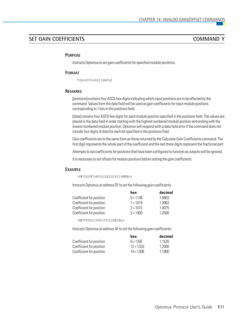
Optomux Protocol User’s Guide 131
SET GAIN COEFFICIENTS COMMAND Y
PURPOSE
Instructs Optomux to set gain coefficients for specified module positions.
FORMAT
Y[positions][data]
REMARKS
[positions] contains four ASCII-hex digits indicating which input positions are to be affected by thecommand. Values from the data field will be used as gain coefficients for input module positionscorresponding to 1 bits in the positions field.
[data] contains four ASCII-hex digits for each module position specified in the positions field. The values areplaced in the data field in order starting with the highest numbered module position and ending with thelowest numbered module position. Optomux will respond with a data field error if the command does notinclude four digits of data for each bit specified in the positions field.
Gain coefficients are in the same form as those returned by the Calculate Gain Coefficients command. Thefirst digit represents the whole part of the coefficient and the last three digits represent the fractional part.
Attempts to set coefficients for positions that have been configured to function as outputs will be ignored.
It is necessary to set offsets for module positions before setting the gain coefficients.
EXAMPLE
>DFY000F1400101E10191148EEcr
Instructs Optomux at address DF to set the following gain coefficients.
hex decimalCoefficient for position 0 = 1148 1.0803Coefficient for position 1 = 1019 1.0063Coefficient for position 2 = 101E 1.0075Coefficient for position 3 = 1400 1.2500
>AFY500113081333126E1Acr
Instructs Optomux at address AF to set the following gain coefficients:
hex decimalCoefficient for position 0 = 126E 1.1520Coefficient for position 12 = 1333 1.2000Coefficient for position 14 = 1308 1.1900
CHAPTER 14: ANALOG GAIN/OFFSET COMMANDS

132 Optomux Protocol User’s Guide
CALCULATE AND SET GAIN COEFFICIENTS COMMAND Z
PURPOSE
Instructs Optomux to calculate and set gain coefficients for specified input positions. The calculatedcoefficients are returned to the host.
FORMAT
Z[positions]
REMARKS
[positions] contains from 0 to 4 ASCII-hex digits. Optomux will set and return gain coefficients for inputpositions corresponding to 1 bits in the positions field. If [positions] is omitted, Optomux will assume abitmask of FFFF. The gain coefficients are calculated using the current values of the inputs. Therefore, thiscommand is only meaningful when the specified module positions are receiving the value you wish toconsider full-scale.
This command is usually used during system installation and calibration when known inputs (full-scale) canbe applied to the modules.
Four ASCII-hex digits are returned for each position specified in the positions field. Values are returned insequence from the highest to lowest module position in the same form required by the Set GainCoefficients command. The first digit represents the whole part of the coefficient and the last three digitsrepresent the fractional part.
Attempts to calculate and set the gain coefficients for an output will result in four question marks ????being returned for that position.
When utilizing the gain coefficients feature, it is necessary to set offsets for module positions beforesetting the gain coefficients.
EXAMPLE
>DFZF2Acr
CHAPTER 14: ANALOG GAIN/OFFSET COMMANDS

Optomux Protocol User’s Guide 133
Instructs Optomux at address DF to calculate and set gain coefficients for positions 0, 1, 2, and 3.
A103111C2127E13684Dcr
Response from Optomux indicating that the following gain coefficients have been set:
hex decimalCoefficient for position 0 = 1368 1.213Coefficient for position 1 = 127E 1.156Coefficient for position 2 = 11C2 1.110Coefficient for position 3 = 1031 1.012
>AFZ5001A7cr
Instructs Optomux at address AF to calculate and set gain coefficients for positions 0, 12, and 14.
A13081333126E74cr
Response from Optomux indicating that the following gain coefficients have been set.
hex decimalCoefficient for position 0 = 126E 1.152Coefficient for position 12 = 1,333 1.200Coefficient for position 14 = 1,308 1.190
CHAPTER 14: ANALOG GAIN/OFFSET COMMANDS

134 Optomux Protocol User’s Guide
CHAPTER 14: ANALOG GAIN/OFFSET COMMANDS

Optomux Protocol User’s Guide 135
SET OUTPUT WAVEFORM COMMAND R
PURPOSE
Initiates a constant waveform at any of the output positions.
FORMAT
R[positions][modifiers][data]
REMARKS
All four [positions] characters must be present.
[modifiers] contains two ASCII-hex characters. The first character specifies the rate of the waveform.Possible rates are given in Table 1 below. The second modifier character specifies the type of waveform(see table 2).
NOTE: A “0” rate terminates the current waveform; no other data is required.
[data] contains four ASCII-hex digits. The first two ASCII-hex characters represent the upper 8- bits of the12-bit high limit of the waveform. The lower 4 bits are 0000. The second two ASCII-hex charactersrepresent the upper 8-bits of the 12-bit low limit of the waveform. The lower 4- bits are 0000.
Period of entire ramp — from 000 to FFF. To calculate actual period, determine the percentage of a full 0 toFFF transition your limits represent. Multiply this fraction by the full-scale period. This result is the actualperiod of 1/2 of a triangle or square wave. It is the entire period of a ramp.
Analog Waveform Commands
CHAPTER 15
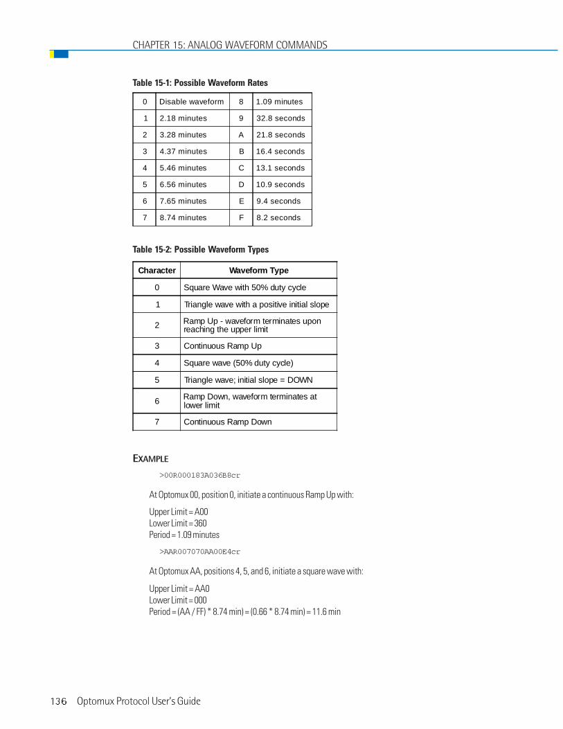
136 Optomux Protocol User’s Guide
CHAPTER 15: ANALOG WAVEFORM COMMANDS
Table 15-1: Possible Waveform Rates
Table 15-2: Possible Waveform Types
EXAMPLE
>00R000183A036B8cr
At Optomux 00, position 0, initiate a continuous Ramp Up with:
Upper Limit = A00Lower Limit = 360Period = 1.09 minutes
>AAR007070AA00E4cr
At Optomux AA, positions 4, 5, and 6, initiate a square wave with:
Upper Limit = AA0Lower Limit = 000Period = (AA / FF) * 8.74 min) = (0.66 * 8.74 min) = 11.6 min
0 Disable waveform 8 1.09 minutes
1 2.18 minutes 9 32.8 seconds
2 3.28 minutes A 21.8 seconds
3 4.37 minutes B 16.4 seconds
4 5.46 minutes C 13.1 seconds
5 6.56 minutes D 10.9 seconds
6 7.65 minutes E 9.4 seconds
7 8.74 minutes F 8.2 seconds
Character Waveform Type
0 Square Wave with 50% duty cycle
1 Triangle wave with a positive initial slope
2 Ramp Up - waveform terminates uponreaching the upper limit
3 Continuous Ramp Up
4 Square wave (50% duty cycle)
5 Triangle wave; initial slope = DOWN
6 Ramp Down, waveform terminates atlower limit
7 Continuous Ramp Down

Optomux Protocol User’s Guide 137
CHAPTER 15: ANALOG WAVEFORM COMMANDS
IMPROVED OUTPUT WAVEFORMS COMMAND V
PURPOSE
Initiates a constant waveform at any of the output positions.
FORMAT
V[positions][modifier][data]
REMARKS
[positions] contains four ASCII-hex digits indicating which output positions are to be affected. Modulepositions corresponding to 1 bits are affected by the command.
[modifier] is a single ASCII-hex digit that specifies which type of waveform is to be generated. Possiblewaveform types are given in the table below.
NOTE: A type “0” wave form terminates the current waveform.
Table 15-3: Possible Waveform Types
Modifier Waveform Type
0 Waveform Off
1 Triangle wave with a positive initial slope
2 Ramp Up, waveform terminates upon reachingthe upper limit
3 Sawtooth, continuous ramp up
4 Square Wave, 50% duty cycle
5 Triangle wave with negative initial slope
6 Ramp Down, waveform terminates at lower limit
7 Sawtooth, continuous ramp down

138 Optomux Protocol User’s Guide
[data] contains a 3-digit value representing the high limit of the waveform, a 3-digit value representing thelow limit, and a 4-digit value representing the period of the waveform. The order is important.
high limit - three ASCII-hex digits representing the high limit of the wave form.000 = zero scale, FFF = full scale
low limit - three ASCII-hex digits representing the low limit of the wave form.000 = zero scale, FFF = full scale
period - four ASCII-hex digits indicating the period of the wave form. The period can range from 0001 to7FFF, each count representing 100 milliseconds (0.1 second to 54.61 minutes). The value represents theperiod of 1/2 of a triangle or square wave. It is the entire period of sawtooths and ramps.
NOTE: The waveform is updated by Optomux every 50 milliseconds, therefore, waveforms with short periods maynot provide a smooth output.
EXAMPLES
>FEV00081FF00C0007808cr
Instruct Optomux at address FE to output a triangle wave at positions 3 with a high limit of FF0, a low limitof 00C, and a period of 12 seconds.
>01V00243F0A00C0078D9cr
Instruct Optomux at address 01 to output a continuous ramp up (sawtooth) at positions 2 and 5 with a highlimit of F0A, a low limit of 00C, and a period of 12 seconds.
CHAPTER 15: ANALOG WAVEFORM COMMANDS
Optomux Protocol User’s Guide 139
CHECKSUM ON ROM COMMAND _
PURPOSE
Initiates brain firmware revision by calculating the unique checksum of the ROM.
FORMAT
_
REMARKS
_ is the underscore character. The underscore is an ASCII 5F hex.
EXAMPLE
>00_BFcr
Revision Identification Commands(for digital surface mount brains only)
CHAPTER 16
Updated: May 25, 2001

140 Optomux Protocol User’s Guide Updated: May 25, 2001
DATE OF FIRMWARE COMMAND ‘
PURPOSE
Identifies brain firmware revision by date of release.
FORMAT
`
REMARKS
` is the single quote under the tilde sign on the computer keyboard and is an ASCII 60 hex.
EXAMPLE
>00`COcr
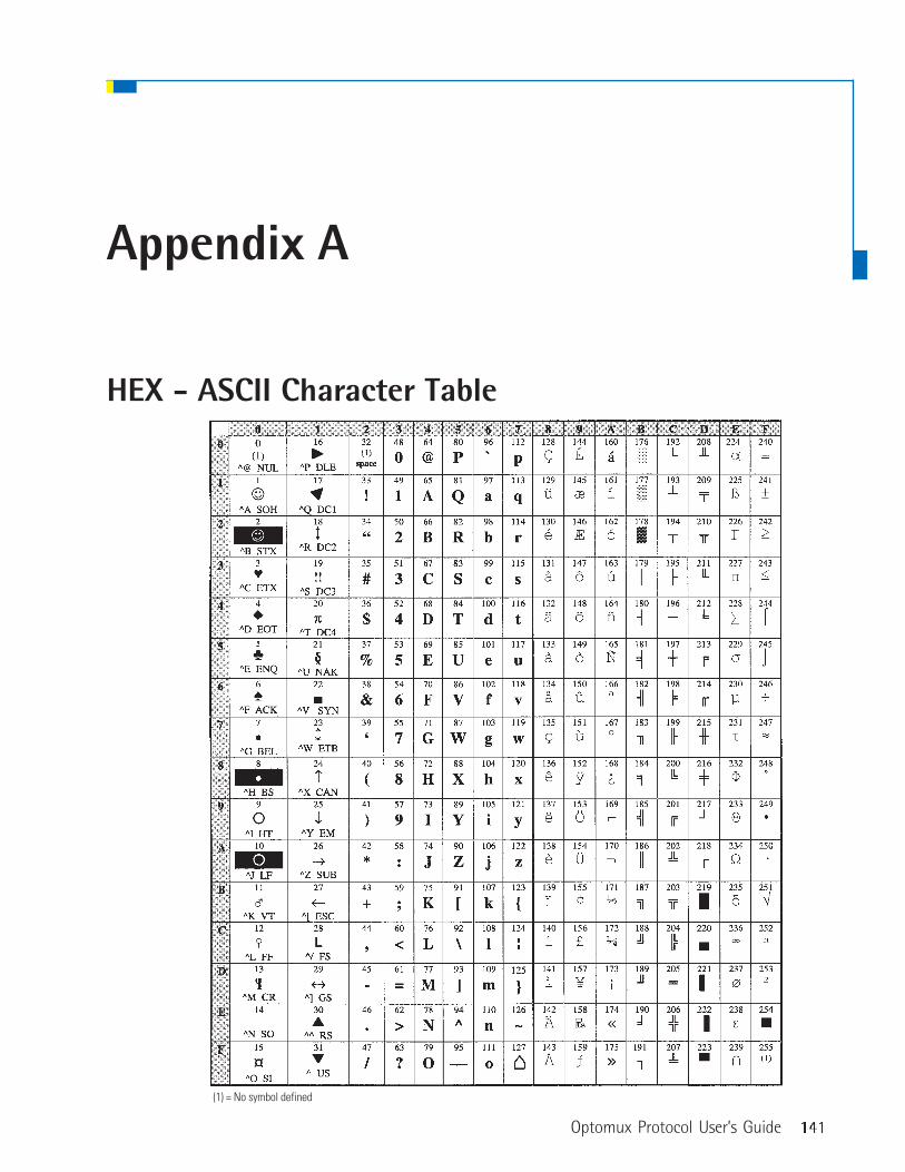
Optomux Protocol User’s Guide 141
HEX - ASCII Character Table
(1) = No symbol defined
Appendix A

142 Optomux Protocol User’s Guide
APPENDIX A
Hex Binary
0 0 0 0 0
1 0 0 0 1
2 0 0 1 0
3 0 0 1 1
4 0 1 0 0
5 0 1 0 1
6 0 1 1 0
7 0 1 1 1
8 1 0 0 0
9 1 0 0 1
A 1 0 1 0
B 1 0 1 1
C 1 1 0 0
D 1 1 0 1
E 1 1 1 0
F 1 1 1 1
HEX To Binary Conversion Table

Optomux Protocol User’s Guide 143
IMPLEMENTING DRIVERS FOR OPTOMUX
Opto 22 has drivers available for Optomux I/O on DOS, Win16, and Win32. However, to implement a driver on otherplatforms, a “generic” Optomux driver is available. The “generic” Optomux driver builds packets to be sent toOptomux hardware and parses the response received. It handles all but the communications with the serial devicesince the serial device is usually platform-dependant. This “generic” Optomux driver is available in the OptoDriverToolkit.
When implementing drivers, it’s sometimes helpful to use a computer running a terminal program as a “sniffer” tomonitor Optomux communications. Normal communications, from a utility such as OptoScan, can be compared tocommunications from the driver being developed.
Appendix B

144 Optomux Protocol User’s Guide
APPENDIX B

Optomux Protocol User’s Guide 145
Surge Protection For RS-422/485 CommunicationLinks
For more information or for catalog requests, contact:
Phoenix Contact Inc.P.O Box 4100Harrisburg, PA 17111-0100
E-mail: [email protected]: (717) 944-1300Fax: (717) 944-1625Fax-on-demand: (800) 944-9901
Appendix C
Updated: June 12, 2001

146 Optomux Protocol User’s Guide
APPENDIX C

Optomux Protocol User’s Guide 147
Troubleshooting Questions and Answers
Q. I send a command to turn on output 5 of an Optomux at address 255 and output 4 goes on.
A. Module positions are numbered from 0 to 15, therefore the fifth bit in the bitmask is for position labeled 4.Following are the bitmask values for each position:
Position Bitmask
0 0001
1 0002
2 0004
3 0008
4 0010
5 0020
6 0040
7 0080
8 0100
9 0200
10 0400
11 0800
12 1000
13 2000
14 4000
15 8000
Appendix D

148 Optomux Protocol User’s Guide
Q. I send a command to activate several outputs, the Optomux responds with no error, but none of my outputscome on.
A. If an output does not turn on, check the following:
1. Make sure you configured the outputs of the Optomux correctly. Optomux defaults to all positionsconfigured as inputs on power-up.
2. If power was lost at any time and returned, Optomux will have lost its configuration. Optomux willhave reported a N00 error to the first command sent after the power-up to indicate that configurationwas lost.
3. If using a digital Optomux, make sure you are using output modules with a 5 VDC logic voltage (OAC5,ODC5, etc.). Sometimes modules with a 15 VDC or 24 VDC logic voltage (ODC15, OAC24, etc.) areinserted by mistake. The LED may turn on or be dim with the 15 VDC and 24 VDC modules but therewill be no output on the field side.
4. If the output LED is on, but the load does not turn on, check the field voltage and wiring. Also, the loadmay not draw enough current to meet the minimum current requirements of OAC5 modules (20 mA).
Q. I send a command message to Optomux at address 0, and I get no response. However, the Optomux’s REClight flashes.
A. The receive lights on all the Optomux boards wired in a multidrop mode should light whenever a commandis sent. Only the Optomux at the address that matches the command message address should respond.When an Optomux unit responds, the XMT (transmit) light will flash. At high baud rates, and for messageswith only a short response (“A” only), the flash will be so brief it may be missed visually.
If the host receives no response, and no flash of the XMT light is visible at the slowest baud rate (300) thencheck the following:
1. Make sure the address in the command message matches the Optomux address. Check the jumpers. Acommon mistake is a reversal of jumpers. All address jumpers (B0 through B7) installed are address 0,and all address jumpers (B0 through B7) removed corresponds to address 255.
2. Make sure the baud rate is correct between the host and the Optomux. All Optomux units on the samelink should be configured to the same baud rate.
3. Make sure you have a solid +5 volts powering the Optomux unit. If the voltage is too low, the RCV lightmay flash, but Optomux will not be able to respond. Measure the voltage at the Optomux powerterminals — not at the power supply.
4. Check to make sure the communications link is wired with the correct polarity and that the A group ofjumpers is configured correctly.
APPENDIX D

Optomux Protocol User’s Guide 149
APPENDIX D
Q. When I read position 3 of an Optomux analog board, I receive a 0000, which converts to a decimal -4,096value when I subtract the 1,000 hex offset.
A. A -4,096 decimal reading may indicate one of the following:
1. You are reading a module position that has no input module installed.
2. You are reading a thermocouple module that has no thermocouple installed or the thermocouple probeis open.
3. An ICTD module which has the ICTD wired in reverse.
4. A 4–20 mA module is wired with reverse polarity.
5. The field connections are made to the wrong terminals. Field connections vary with each module.Refer to the Optomux Family Data Book (Form #524) for information on wiring each specific module. Ingeneral, field connections made to the terminals on the rack are made to the terminals labeled UPPER(closest to module), and if the module has terminals on the top of the module, connections would bemade there. Analog racks have the terminal channels labeled from 1 to 4 (or 16). These channelscorrespond to module positions 0 to 3 (or 15) respectively.
6. If all inputs on that board have the same -4,096 reading, then check to make sure the board has +15and -15 VDC at the corresponding terminals (with reference to the terminal that is markedCOMMON).
Q. I receive a large number of checksum errors (N02) when I send commands to Optomux.
A. Make sure that you are using twisted pair cable. The RS-422/485 network is only reliable when thecommunications cable is twisted (+ and - lines of EACH pair twisted together), with at least 1/2 twist perinch. Sometimes, the wire is twisted but one of the connections of a pair is actually used as the mate to theopposite pair ( - of one pair used as - of opposite pair). This cross-twist condition is usually due to jacketedtwisted pair cables which have a wire of each pair with the same color code. In this case, strip the jacketback far enough to properly identify the individual pairs.
You should also check the Group A jumpers to make sure the termination and bias jumpers are correctlyinstalled.

150 Optomux Protocol User’s Guide
APPENDIX D
Optomux Protocol User’s Guide 151151151151151
If you have any questions about this product, contact Opto 22 Product Support Monday through Friday,8 a.m. to 5 p.m. Pacific Time.
Phone: 800/TEK-OPTO (835-6786)951/695-3080
Fax: 951/695-3017
E-mail: [email protected]
Bulletin Board System (BBS): 951/695-1367http://bbs.opto22.com(24 hours a day, 7 days a week)
OptoWorld Wide Web site: http://www.opto22.com
When accessing the BBS, use the following modem settings:
• No parity, 8 data bits, 1 stop bit
• Baud rates up to 28,800
• Z-modem protocol for uploads and downloads (optional but recommended)
When calling for technical support, be prepared to provide the following information about your system to theProduct Support engineer:
• Software and version being used
• Controller firmware version
• PC configuration
• A complete description of your hardware and operating systems, including:— jumper configuration— accessories installed (such as expansion daughter cards)— type of power supply— types of I/O units installed— third-party devices installed (e.g., barcode readers)
• Specific error messages seen
Product Support

152 Optomux Protocol User’s Guide