or - real automationrealautomation.ca/publicintroa1.pdf · gieck engineering formulas 7th edition....
TRANSCRIPT
® Page -1-
THE SECRETS OF INERTIAL PROPULSION DRIVE®
Or
The power of linear displacement frequency modulated oscillating flywheels®
Or
The Combined Linear and Rotational non uniform Motion Inertial Propulsion®
Or
The Rotational to linear coupled non-uniform Motion Inertial propulsion®
Or
The Inertial Propulsion Drive Cookbook®
Or
How to build an Inertial Propulsion Drive®
Or
A logical path taken, The Inertial Propulsion®
Or
The controversy of Inertial Propulsion®
Or
Newton’s unfinished Theorem®
Or
Energy Within, The Inertial Propulsion®
Or
The Power of surging centrifugal forces: The Inertial Propulsion®
A study is presented to determine the viability of inertial propulsion and the path to fulfill the realization
of the inertial propulsion method. This study does not extrapolate that the presented technology is in any way connected to the UFO phenomena, however the material presented
identifies the incongruent logic applied by traditional science to discount inertial propulsion.
Table of Content:
Page#:
2 Abstract
2 Field of the Inertial Propulsion
4 Assumptions
5-53 The fundamental background of the inertial propulsion
53 Concluding the fundamental background
54 Description of the drawings
55 Technology used by the Inertia drive
56,64 Proofs
65-67 Functional elements of the inertia drive
68 Description of the inertial propulsion cycle
69-82 Mathematical and physical principle of the inertia drive
83-95 Detailed description of an example inertia drive
Author: Gottfried J. Gutsche, Web site: www.realautomation.ca
With greatly appreciated support from my wife Margaret, son Eric, Sandy and my daughter Julie.
All Rights Reserved, Copy Rights Protected ® 2012-1, Patents Pending.
Price :49.95 CD$
DO NOT COPY OR TRANSMIT THIS PUBLICATION OR ANY INDIVIDUAL PART OF IT
® Page -2-
THE COMBINED LINEAR DISPLACEMENT AND ROTATIONAL
MOTION INERTIAL PROPULSION DRIVE®
Abstract of the inertial propulsion driveA novel method and device for self-contained timely sequential vehicular
inertial thrust drive is presented, comprising a tandem mechanical frequency
modulated oscillator using the combined effort of linear and rotational inertial
reluctance contained in the inertial mass of flywheels. The flywheels are having
parallel axial orientation, opposite free wheeling rotation and opposite alternate cyclic
linear free flowing non-uniform reciprocal motion in union with vehicular travel by
means of a linear to rotational-coupled motion. The linear to rotational-coupled
motion accomplishes the cyclic realignment of the flywheel linear displacement
motions to combine the linear and rotational motion mass combinations into one
directional gradient vector sum motivating thrust drive. The free flowing linear and
rotational inertial reluctance of the flywheel mass is used as the motivating kinetic
drive energy by timely non-uniform mutual reciprocal separation against the device
mass and the freewheeling rotational inertial reluctance of the flywheels’ mass
moment is used to absorb mutual reciprocally contrary rotational kinetic energy. An
integral motor- generators rotor contained within each flywheel accumulates
rotational kinetic energy subsequently used for the propulsion of the device and is
used to obtain the frequency modulation and non uniform motions. A rotor attached
variable rotational - to - reciprocating transmission is directing the accumulated
kinetic energy non-uniformly mutually reciprocally into the device in direction of
vehicular travel and into the free flowing linear and rotational flywheel mass. The
cyclic sum of all the mutual reciprocal impact actions represent a closed loop with
two self contained superior centripetal inertial thrust drives.
Copyright 2011-7 by Gottfried J. Gutsche ® All Rights Reserved, Patents pending.
FIELD OF THE INERTIAL PROPULSION
The present publication describes an inertial propulsion device and method for
developing an unilateral self-contained propulsion force in a predetermined direction
using the combined energetic effort of linear to rotational-coupled mass motion. This
publication seeks to present, that the transmission coupled rotational to linear
displacement cyclic mass motion inertial reluctance of flywheels, operating
alternating in the frequency modulated complex Cartesian grid plane and in the steady
frequency real Cartesian grid plane, is developing self contained directional gradient
impulses. The current issue of this publication represents the current result of Real
® Page -3-
Automation’s research into the combined effort inertial propulsion.
The main objective of this publication is to describe, in an easily digestible
practical format, the formulas, methods and proofs used to engineer the inertial
propulsion device. It is postulated that practical established existing mechanical
construct examples, used within the publication, have an indisputable level of
certainty in comparison to purely abstract physics thinking. The level of math and
physics is kept at or below mid-university level. The publication represents a
thorough scientific investigation comprehensible by a general audience, school and
media personnel with firm knowledge of college math and physics having a keen
interest and desire to investigate new technologies and the latent historical barriers
for an earlier discovery.
The presented calculations for the engineering of the propulsion device uses
the units of kinetic energy in Kgfm, Joules and the N to illustrate the forces at play
in easy terms, 1 kgf (force) is simply the force 1Kg mass delivers to the ground in
Paris France, which is only fractional different in the readers location and everyone
buys 1 kg of potatoes, while it is not easy to relate to a 1 Newton force. The meter is
conveniently reproduced with a measuring tape and the product of Kgf multiplied by
the meter is the kinetic energy of 1 kgfm = 0.102 Joule (the force of 1 Kgf exerted
over 1 meter distance = 0.102 Joule). Which is about the electrical energy of
0.003-watt hour. The measure for the frequency of rotation is RPM revolution per
minute and the angular velocity omega to illustrate the cycle frequency used. RPM
is more commonly used in the eggbeater than angular velocity. While it might be
considered old fashion to use Kgf and RPM, a technical person can appreciate N and
Omega while a complete layman will appreciate Kgf and RPM.
This publication uses references selected on the merit of highest certainty and
reality based on practical time proven examples. The Engineering reference: Kurt
Gieck Engineering Formulas 7Th Edition. For verifying examples this publication
uses: Schaum’s 3000 Solved Physics Problems by Alvin Halpern, Schaum’s Feedback
and Control Systems by DiStefano. Furthermore: Group 24 by Jean-Pierre Gazeau,
Physics for science by M. Browne and Mechanics presented in a new form by
Heinrich Hertz.
For simplicity and premier certainty, differential calculus expressions of
parameter instantaneous delta/delta rate of change (derivatives/slopes) are avoided,
because of the high uncertainty and complexity how the instantaneous localized rate
of change (slope) varies within the propulsion working cycle time-frame by the
applicable physics/math functions. Instead, the primary rule of the slope of the secant
line, the mean value theorem is used, describing the average slope and integral of the
® Page -4-
parameters magnitude Y-axis-gain/X-axis-gain changes spanning the propulsion
cycle. This principle is also commonly referred to as: “Rise over run”. The word
“gain” is used to indicate the change (Gain=Rise) and is for the entire cycle and not
an infinitesimal small delta. For example: Velocity, gain / time is acceleration,
Velocy, -gain /time is de-acceleration. The secant line rule perfectly describes the
average rate of change over the entire propulsion cycle. For example: Speed, average
= Displacement, gain / Time, duration; and further: Force, average = mass *
Velocity, gain / time, duration. The * is used as the multiplication operator. The
average or mean value can then be used in conjunction with vector math to arrive at
the final effective parameter magnitudes as is common practice in electrical
engineering.
If the reader is unfamiliar with the following math concepts it is recommended
to review the following References:
www.en.wikipedia.org/wiki/Mean_value_theorem and
www.wikipedia.org/wiki/integral
www.ehow.com/how_4963946_calculate-average-force.html
www.en.wikipedia.org/wiki/vector_space
www.en.wikipedia.org/wiki/Feedback#In_mechanical_engineering/
Rotational Dynamics and the Flow of Angular Momentum:
www.physikdidaktik,uni-kallsruhe.de/.../rotational-dynamics.pdf
The mechanisms described by this publication are subject to patent
applications:
US 11/544,722 , US 12/082,981, US 12/932857, CA 2,526,735.
ABOUT THE AUTHOR
The author, Gottfried J. Gutsche has an education in Control Engineering,
Cybernetics and Electrical Engineering applying to the electrical control of motors
for robots in factory automaton technologies. In particular, attended courses teaching
machine inertial mass manipulation and control loop stability analysis. Subsequently
worked 28 years in data progressing technologies, from the end era of the mechanical
data processing technologies, the era of emerging discreet transistors with discreet
wiring technologies, the era of emerging integrated circuits to the mature technologies
of large-scale circuit integration for very large computer systems. From there the
Author operated a consulting service designing automation equipment. The previous
work experience fine-tuned the author to deliver consistent high degree of quality
analysis on difficult mature problems relating to inertial mass manipulation controlled
by computers.
® Page -5-
ASSUMPTIONS
The processes and the methods of the present inertial propulsion systems are
based on known laws of physics and therefore have the same inherent assumptions
and limitations as these known laws of physics. However the assumptions of the mass
motion laws are examined to determine how these assumptions influence the
operation of the presented inertial propulsion drive.
In summary: The following physics laws and their inherent assumptions apply
and the process in its functional entirety has been verified with experiments and
working models:
The law of continuity of physics laws within a moving platform, the law of
continuity for physics in general.
The laws of periodic cyclic rotational to linear coupled mass motion in the
complex Cartesian rotational vector grid applying to periodic energy avalanche
discharges having the root cause in the symmetry of the stored energy to the
centripetal force exerted over the rotational displacement distance.
The law of uniform proportional relationship of mass motion acceleration in
relation to the force applied in uniform motion systems.
The law of escalating kinetic energy content for the increasing velocity of mass
motion.
The law of conservation of kinetic energy and energy in general is assumed and
proven within this publication to be the primary conservation law for rotational to
linear displacement coupled non uniform mass motion.
The law of conservation of momentum, applied within linear mass motion, for
angular mass motion and for rotational to linear coupled mass motion and the
conservation of momentum for every very small increments of momentum in the
preceding three mass motions within its limitations of validity.
The law of equal reciprocal reaction to the action of an impulse and its limits
of validity for the cyclic combined rotational to linear displacement coupled mass
motion.
The law of the motivation of a mass with unbalanced forces applied.
The directional reversibility of Physics principle.
THE FUNDAMENTAL BACKGROUND OF THE INERTIAL PROPULSION
Physics is the study of matter, energy, space-displacement, time, how they
interact in nature and the realty prove of theses interactions. Throughout this
® Page -6-
publication the physics of matter, energy, space-displacement time, how they apply
to inertial propulsion and the applicable reality prove is the subject under scrutiny.
In the very beginning of mathematical and physics thinking was Archimedes
statement: Give me a fixed point to stand on and I will move the Earth. This statement
seems to tell us that there must always be a fixed point to move an object of
substance, therefore, the notion of inertial propulsion ought be rejected by thinking
in terms of levers and pulleys. A new way of thinking in science was started in the
Renaissance by logically investigating and proving physics principles with
experiments. In particular, the subject of inertial mass motion was brought into the
forefront of science by an experiment by Galileo. Galileo rolled cannon balls down
an inclined board having equal spaced notches inscribed. The clicking noises made
by the cannon ball hitting the notches were having an ever shorter time interval and
ever higher pitched sound indicating a non uniform temporal behavior of this inclined
notched board system. Accordingly, the potential energy depleted in form of dropped
height was causing an exponential-accumulative increase in cannon ball speed.
Galileo presented a lengthily math solution to the notched board experiment in form
of a complicated word problem requiring very high disciplined thinking skills. From
there, a quest developed to improve Math-Algebra tools to better describe the
exponential behavior of Galileo’s experiments. Furthermore, two continental
European scientist G. Leibniz and C. Huygens, with cooperation, identified Galileo’s
notched board experiment to be related to the progressive performance of projectile
motions hurled by machines of war delivering the progressive ability to do destructive
work against castle walls. They called the exponential ability of mass motion velocity
to do destructive work “Vis Viva”: The living Force contained within an inertial mass
in motion. An ancient known principle. Leibniz wrote a book teaching calculus Math,
to arrive at the average values exerted by these exponential systems using a set of
algebraic exponent rules making cumbersome word problems unnecessary. Huygens
investigated Galileos’ notched board experiment when extrapolated onto the swing
of pendulums and wrote two very important papers “The Centrifuga and the The
Oscillatorium” laying the foundations of rotational dynamics based on potential
energies transferring into motion quantities. With these papers Huygens Invented the
centrifugal force and the moment of inertia and gave a pre-notions of Lagrangian,
Hamiltonian and Hertz mechanics. Huygens and Leibniz maintained a lively
correspondence and visits discussing these principles openly in great detail,
correcting-helping each other in an amazing collegial manner without any fear of
losing intellectual property. However, the most prominent and successful scientist of
the Renaissance was Newton. Newton had the great and far reaching idea to remove
® Page -7-
the exponential mass motion behavior by analyzing Galileo’s notched board
experiment over uniform time intervals INSTEAD of uniform distance intervals.
When analyzing linear displacement inertial mass motion velocity in uniform
(isochronous) time interval progression, the exponential- accumulative temporal
behavior we have seen in the displacement analysis disappears and an uniform
proportional relationship of force and acceleration is presented, wherein the
displacement is the area under the motion curve, an “apparently” easily
understandable correlation. The most import advantage of this time based analysis is
that the force is having a mean value spanning the motion velocity-gain time duration.
Newton was then applying the time base analysis successfully to planetary arc
motions around the sun and published a book: “The Principia” describing in detail
how a time based analysis applies to mass motion. Within his Principia publication
Newton also presented his very important invention of the centripetal acceleration
which solves the forces applying to an inertial mass moving in arc motions in
opposite orientation to Huygens 19 years prior invention of the centrifugal force.
From his Principia writing and further statements it appears that Newton regarded the
discovery of the centripetal acceleration applying to planetary motions to be his most
important work. However, during rotating pendulum experiment having simultaneous
rotary motions and linear displacement coupled reflections, Newton encountered
similar behavior Huygens had described in his publications in previous years. These
combined motions were solved by Huygens with his displacement based analysis of
potential energy transferred into (kinetic) motion energy and are not necessarily
(easily?) Directly solvable with Newton’s time based analysis. Newton seemed to
sense a more complex system here, calling theses combined mass motions
investigation too numerous and tedious for final analysis. To keep his Principia
uncluttered and to avoid using or referencing Huygens publications, he did a very
smart move by separating linear displacement mass motion from the troublesome
combined motion pendulum experiments and apparently let future scientist to develop
better Physics tools to describe these systems. Evidently, we have here somewhat an
unfinished theorem ala Fermat! Fermat ran out of paper, Newton ran out of time and
patience. Newton, however, seemed to cast these pendulum experiments not only off
into an uncharted area, but cast the subject off limit by a somewhat conflicting all
encompassing pronouncement. Newton postulated his third law of mass motion by
arguing that there is always an equal and opposing reaction to any mass motion
action. The ALWAYS argument appears to include also Huygens combined linear
displacement to rotational motion reflections against pendulums. This is, however,
un-provable because of Newtons’ stated near infinite possible inter correlation and
® Page -8-
reiteration of the three possible motion directions of one single unit of mass: The
axial rotation, the tumbling head over heels motion and the overall forward motion
when interacting between multiple units of mass. Newton accordingly writes about
his combined rotational to linear displacement reflections against pendulums: “But
these reflection I will not consider in what follows (in the Principia) and it would be
too tedious to present every and all examples of these combined motion reflections”.
From these statements it is un-clear how Newton intended to proceed to proof his
claim of the universal reach of his third law. In retrospect one has to suspect, the
ALWAYS argument hopefully has some underlying un-published experiments as its
foundation then being a purely intuitive thought process.
The basic traditional operational principle of an Inertial Propulsion is the
generation of an unidirectional motivating self contained energetic force impulse
(Thrust) within a vehicle, in direction of the intended motion of the vehicle. A
self-contained impulse is self-contained if there are no force exertions against a fixed
point external to the vehicle and the root cause of the impulse is an internal source of
energy quantity. The internal source of energy quantity is the work of an internal
motor force over a distance. The force impulse must be regarded as the motivating
agent of the isolated system of the vehicle and is the product of force and time
interval applied to the whole aggregate mass of the vehicle. The internal product of
force and time must be larger in direction of the intended motion of the vehicle to
propel the vehicle forward.
The presented Inertial propulsion drive is employing a dynamic process using
the combined effort of the two vector dimensions of the inertial reluctance contained
in the mass motion of flywheels, the linear displacement and angular (rotational)
reluctance to motion. The dynamic process generates a timely sequential variable
impulse mutually reciprocally exerted between the combined linear and rotational
inertial mass reluctance of a flywheel and the aggregate sum of the Vehicle mass. The
cyclic dynamic process further generates three timely repetitive identical (base)
inertial mass motion potential energy conditions and one superior peak initial
potential energy condition in a closed loop mutually reciprocal energy flow. This
means, the timely sequential impulse having a superior magnitude in direction of the
intended motion of the vehicle is applying Newton first law: The aggregate inertial
mass of a Vehicle remains in motion until acted on by a subsequent superior opposing
force.
The question whether or not such a self contained motivating force impulse can
exist within an isolated system of a vehicle was raised again early in the 18th century
when clockmaker attempted to build clocks capable of sustaining the local time of the
® Page -9-
port of departure for longitude navigation. Here again we have Huygens’ rotational
pendulum mass motion with linear displacement reflection being employed within
these clocks and Huygens was heavily involved, from the very beginning, in finding
the perfect clock for ship navigation. Clockmakers were confronted by an intriguing
problem: It seems, no matter how ingenious such clocks were devised they either
advanced or retarded when contained on ships in comparison to the port of departure
local time. This of course means; the clocks gained energy or depleted energy over
time while clocks are designed to deliver very exact equal energy portions over very
long time durations. It was determined that the complex motion of the ships was
causing the change in clock timely energy distribution magnitudes. This principle is
the theme of the endearing film “Longitude”. In this true story film, the clockmaker
Jon Harrison determined that a certain motion of the ship, his clock creation was
tested on, delayed his experimental test clock a relative equal amounts of time thereby
saving the ship from a navigational disaster. Harrison was able to extrapolate the time
delay of the clock to the changes in initial potential energy conditions of the clock
pendulum swings caused by the ship motion impinging on the pendulum motions.
The films story is documenting a brilliant performance of human intelligence. How
can we explain such a true phenomena with Newton’s Third Law of ALWAYS equal
reaction to an action? How can an action of the isolated system of a ship react on the
kinetic energy of a clock contained on the same ship without direct transmission
traction simply by the oscillating motion of masses? Since the ship to clock energy
transfer relationship is a documented reality, then it can be argued with accuracy:
Because of the reversibility of physics principles, energy and impulse must be
continuously transferable from very large clocks mounted within vehicles in a
reversed process. However science dismisses such phenomena as caused by
reiteration / reverberations / sticktion against the surface of the earth without
delivering a comprehensive physics description / proofs of these actions. If we need
the surface of the earth as a reference source to motivate a vehicle with a self
contained impulse, why is it not possible to use a second clock delivering an identical
directed impulse magnitude but in a mutually opposing mass motion direction
mimicking the reference source? Yes, this publication seeks to present that such a
system of tandem mechanical oscillators have an unidirectional self contained
impulse capability generating its own reference source. This publication’s aim is then
to provide an answer to what these reiterations / reverberations / sticktions are which
motivate vehicles without traction of wheels. Accordingly, in view of the ship
chronometer reality without any further ado, we must already concede that inertial
propulsion must be possible and patents claiming such capability must be carefully
® Page -10-
examined for individual validity, the question remains at what magnitudes.
The Inertial Propulsion drive motivating force impulse is a vector force, which
is an applied force magnitude spanning a three dimensional direction, having a time
duration. The time duration covering all functions of the isolated system at the same
time-instant can be defined to be the cycle time duration (the passage of time during
one complete rotational cycle). Therefore using the law of mean value, the analysis
of the dynamic process can concentrate on the average force, applied to or delivered
from the cyclic motion of the inertial masses over their total displacement (motion
distance) and within the cycle time interval, which is the average flow of (kinetic
work) energy within a time frame (flow of energy quanta within the time domain).
The flow of energy or work must be viewed as the analysis of the vehicles’
motor size and the position of the gas pedal. The kinetic energy is the energy content
of a mass in motion having a measurement of 1 kilogram, force, meter, Kgfm=0.102
Joules in comparison to all other energy forms in nature.
Energy is, of course, what marks the very first step of becoming human by
learning the art of lighting a fire at will The energy quanta per time domain is
represented by the sustainable magnitude of the campfire humans maintained during
the time of rest. Energy is still the most important commodity and issues facing
humans today: Where can we get more energy? The flow of energy within a time
domain pertains to the choice of the car engine Hp size and what energy consumption
per person is political correct?
The concept of a quantity of flowing work/kinetic energy within a time frame
having a flow direction, a source and a sink, is an extension to the traditional
approach of work performed within a time frame, which is in traditional view power
or horsepower with the addition of flow direction. Work/Kinetic energy quantity flow
is a more suitable analysis approach for the presented propulsion concept, evident
from work/kinetic energy transmitted over hydraulic power lines, transmission shafts,
kinetic energy absorbed by flywheels and the transport of items on a conveyor belt.
In mathematical physics term kinetic energy/work flow is the delta energy/work per
delta time power=de/dt.
The concept of kinetic energy flow analysis in the time domain and the force
in the displacement domain (the passing of distance) and the force in the time domain
(the passage of time) are used within the body of the publication to prove the
directional force impulse gradient by geometric figure comparison when the vehicle
is in motion and held at rest. This is because: A motor is generating mass motion
kinetic energy by applying a force over a distance (force * displacement), which is
the area of a geometric figure in the displacement domain. The displacement domain
® Page -11-
analysis is then a geometric figure where the base-line is a straight line representing
the passage of distance and the area above the base-line and below the curve is the
magnitude of the average force. In contrast: Impulse is the play of a forces within the
time domain (the passage of time) which is the area of a geometric figure
circumscribed by the play of forces where the passage of time is the base-line of the
geometric figure and the area above the base-line and below the curve is the distanced
displaced. Inertial mass motion caused by the steady acceleration is the having a
straight line curve in the time domain analysis and a progressively flattening curve
in the displacement domain analysis, this has been demonstrated by Galileos’ notched
board experiment.
At this point, having viewed the basic principles of mass monition analysis it
is important to compare the underlying physics principle pertaining to the
displacement domain analysis and the time domain analysis. What are the physics
principles of each analysis explained in an indisputable practical format?
The displacement domain analysis is telling us that the nature of inertial mass
reluctance requires a progressively larger force per uniform distance intervals to
increase the mass motion velocity. This is because an increase of mass motion
velocity instills into the inertial mass a larger ability to do work, the Vis Viva is
depending on the previous speed of the mass motion velocity. The “Vis Viva” is then:
#1)Force, mean, value= ½ mass * (V²,new, speed - V²,previous, speed) / distance
From this formula we can extrapolate that the displacement POSITION,
within a long motion quantity, were the maximum gain in speed is occurring will
significantly change the overall FORCE mean value magnitude. It is also very
important to note here the ½ modifier in this formula. The ½ modifier tells us that this
formula applies to a uniform mass motion. A uniform mass motion is a motion where
the mass motion velocity increases a uniform amount for every uniform measure of
time interval. Furthermore, uniform motion has ½ the average speed of the speed
gain. From this displacement analysis formula Newton’s third law can be extrapolated
that for linear displacement reflection the effective net force effort will be zero within
an isolated system. However, Inertial Propulsion is performed with a combined
rotational and linear displacement motion in a non uniform motion progression
(Newton’s too numerous and tedious experiments) where the ½ modifier is only
applicable to half of the propulsion cycle or applicable to very small delta sections
of the motion where long motions are only solvable with methods of calculus
integration.
In contrast, the time domain analysis is telling us that a sum amount of impulse,
the summed product of force and time duration, will impart an increase of
® Page -12-
proportional amount of inertial mass motion velocity independent of the time
position, independent of linear displacement position or previous motion history
considerations, as long as the motion is well below the speed of light. The Force is
herein expressed as:#2) Force, mean value=mass * Speed, gain, linear displacement/ time, duration
To illustrate the two analysis system side by side in practical terms one has to
look at the operation of the ideal race horse having its maximum speed gain at the
race finish line and having weightless-mass-less-frictionless legs:
In the displacement domain we can say the horse forages on oats which has an
equivalent of energy printed on the serial box in Kcal which contains a proportional
equivalent of force multiplied by displacement distance Kgfm = work, 1 kcal or
0.0023 kgfm. This means there isn’t much energy in terms of kgfm in a box of oats.
The horse must moves its legs for every uniform measure of distance covered by its
body with a force which is depending on the previous speed of its body according
to the work:
Force * distance = 1/2 mass * (new, speed² - previous, speed² ). This means; the faster the horse runs the progressively higher is the required
force per measure of uniform distance. We can conclude, the speed of the horse is
limited by the magnitude of the force it can deliver over the uniform measure of
distance from the quantity feed of oats it previously has received.
In the time domain analysis we say: The horse is applying a uniform measure
of force multiplied by a uniform measure of (isochronous) time duration intervals,
which is impulse, to its legs which motivated the body of the horse to a proportional
incremental higher velocity independent of any previous velocity magnitudes.
Impulse = Force * time, interval = mass * speed, gain.
In the time domain analysis it seems easy for the race horse to win the race,
more impulse results in proportional more speed. But obviously, the time domain
analysis does not take into account how often the horse has to move its legs per each
time interval of the speed, thereby, using more and more of the force effort for
moving just only its legs back and forth in ever shorter time intervals. We can say:
The time domain analysis has the disadvantage of NOT having a build in description
of cause and effect. What is causing the force to appear in the first place and what is
causing the force to be exerted at an elevated speed? Where is the potential energy
causing the force to appear? While the time domain analysis provides the advantage
of an uniform relationship of impulse to mass motion speed gain, it disregards the
mechanical ability of the horse to deliver such a mass motion impulse at a speed and
most importantly it disregards that the horse having the highest average speed will
® Page -13-
win the race, if the total race speed-gain at the finish line is identical between each
horse participating in the race. Accordingly: If the horse delivers a higher force per
the uniform equal time intervals at the beginning of the race, while the total sum of
all impulses remain constant, it has a higher chance to win the race. This, however,
is not possible to extrapolate from the time domain analysis with formulae#2 , but can
be extrapolated from the displacement domain analysis with formula#1. The
disadvantage to co-relate the impulse to the average velocity is severely limiting the
applicability of the time domain analysis. For matter of fact, the average force per
time interval delivered by the race horse can not be calculated with impulse or
momentum formula #2 until the energy magnitude is known, because, the magnitude
of the acceleration, the of root cause of the motion and the root cause of the race time
duration, is depending on the energy expended over the race track distance:
#3)Acceleration, average = Energy, work, magnitude/(distance, track * mass, horse
The relationship of energy and acceleration is a displacement domain/energy analysis,
a uniform proportional relationship, double the energy magnitude will generates
double the acceleration for the same mass. The acceleration/work theorem is always
true no matter how the force varies over the distance because of the before mentioned
mean value theorem and the conservation of energy theorem, no energy can be gained
or lost. So, the conclusion is: The horse race can NOT be calculated/predicted in the
time domain until the race is finished and the time duration is known because the race
time duration itself is depending on the displacement domain analysis, an energy
analysis. However the time domain analysis within Formula #2 can be expanded by
the linear displacement on both sides, left and right side of the formula, to arrive at:
#4)Energy, work, magnitude = mass, horse * Speed, gain * Speed, average
Accordingly, energy work is directly proportional to the product of speed gain
multiplied by average speed of the horse wherein the mean value of formula #2 is
preserved. Formula #4 has a high certainty level because it is derived from the mean
values of force and it will be proven to deliver always the true absolute minimum
value of work performed and energy expended. The logic of formula #4 seems to
suggest the possibility that a steady cyclic repeating speed gain amplitude and a
variable average speed per race track distance in a linear displacement mass motion
can produce a directional difference in impulse magnitudes when comparing two
directional opposing horse races. The difference in impulse will be analyzed with a
two conveyor belt system and proven to be correct. However, further analysis proves
also, purely linear displacement systems, working with an indivisible conveyor type
mass combinations, do not and cannot produce a working inertial propulsion system
as correctly postulated by Newton’s Third Law. However this postulation will be
® Page -14-
again analyzed with variable mass motion combinations when considering mutual
reciprocal motions on a frictionless surface and will be found to be non universal.
This limitation is applying to purely linear displacement motion of the horse race, it
can also be extrapolated by analyzing the finish-line photos of a horse race.
Consecutive photos taken at the finish line will show that the speed of all horses are
in most cases identical. This means the momentum of each horse is having an
identical momentum when we assume that the mass of each horse is identical.
Accordingly, each race horse received an identical sum of impulses. This now seems
a paradox as each horse is showing, in the photos, a different distance to the finish
line. Yes, here we must again point to the difference in analytical capabilities of
displacement domain analysis versus to time based analysis. Furthermore, in case the
most eager horse in the race is attempting to accelerate a few seconds before entering
the finish line and actually manages to move up in position only 1 cm short of an
equal position with the lead horse. Then we can say: The eager horse has performed
a higher impulse sum and has acquired a higher momentum as the lead horse but is
still in not winning the race. This is of cause, because the eager horse needs an
advantage in acceleration to catch up with the lead horse position, then displacement
multiplied by acceleration is an energy consideration. Then we can postulate:
Comparative, mass motions having equal position and equal time durations can have
unequal impulse - momentums. This what we are trying to accomplish, unequal
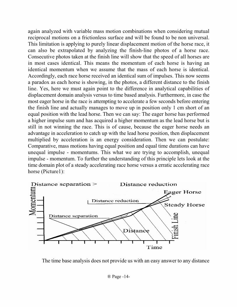
impulse - momentum. To further the understanding of this principle lets look at the
time domain plot of a steady accelerating race horse versus a erratic accelerating race
horse (Picture1):
The time base analysis does not provide us with an easy answer to any distance
® Page -15-
questions pertaining to the stated mean value theorem before the race started. Only
when applying difficult integration of all the instant speeds, after the race is finished,
we can correlate the sum of all the instant speeds to the horse position per time. This
integration can not be performed before the race because the progression of the
racehorse speeds -accelerations are unpredictable. However, such a velocity
integration is actually a displacement domain analysis in disguise, because the instant
speed * delta time = delta distance, where the sum of the deltas is then the total
distance. Furthermore, The integral of impulses can not provide us, in any way, with
an answer to race horse position at a time duration, it only provides us with a
momentum magnitude. In contrast, the displacement domain analysis provides us
with a position analysis of each race horse with the possibility to convert to a race
time duration by co-relating the energy/work magnitudes to the average speed. This
is how Christiaan Huygens solved his pendulum problems between anno 1659-1673
up to 14 years prior the publication of Newtons’ Principia. However, did Huygens
know about the impulse to momentum limitation of the purely linear motions, and
importantly, did he need to know the impulse to momentum relationship to solve his
oscillation problems? Apparently not. And from these points of initial analysis we can
postulate already with certainty: Machinery like the Race Horse, the Indy 500 Car
racer, the Inertial Propulsion or any other machinery, where position in relation to
time progression occurs, must be analyzed in the displacement domain. Because, it
is not possible to extrapolate the sum of impulses and the resulting momentum to the
root cause of the motion. Here we arrive at the first important postulation of this
publication:
The root cause of inertial mass motion is the exertion of a work quantity from
a quantity of potential energy at each displacement positions, causing a gain in
speed at each position, causing an accumulative average speed at each position
in relation to the starting position, causing an accumulative total momentum and
causing the total motion time duration over the total accumulated displacement
distance.
Accordingly, when someone maintains that all inertial mass motion problems
are solvable with formula #2, without any actual real displacement length parameter
considerations, we surly entitled to say: You surly disregarding the reality of energy
conservation. This principle will be proven to final exhaustion with many examples.
To complete the range of analysis by including all possible changes in variables
we must include also the analysis in the frequency domain, the play of forces in
relation to a change in cycle frequency. Because the presented IP system works with
the variations in cycle frequency.
® Page -16-
Reference: www.physics.int/motion-graphs/
However, all four methods of analysis are important depending on the physical
environment the Inertial Propulsion vehicle is in. While a vehicle is within an intense
gravitational field, the analysis must be in the time domain, because the vehicle is not
moving, the play of forces are only countering the gravitational force (hovering) and
all kinetic energy flow quanta is being recycled within the vehicle. Thereby one can
postulate that the generated force holding the vehicle in the hovering position is a net
ZERO energy consumption because of ZERO MOTION of the vehicle, except
friction and efficiency losses of the moving Internal inertia elements. When the
vehicle is in a relative low gravitational field, then the analysis must be in the
displacement domain and in the time domain, because the vehicle is moving and is
performing work against the force of gravity at the same time. Thereby the vehicle is
displacing for each quanta of kinetic energy per time frame (per operational cycle)
and therefore the aggregate sum of the vehicles’ masses is absorbing kinetic energy.
This very important principle and its foundations are proven in the body of the
publication. The exception to this simple rule is the consideration of the thrust timing
each cyclic dynamic process per vector dimension of inertial mass motion is
delivering. This consideration has to be entered into the analysis. If the effective trust
timing is less then continuous, having time gaps, then, there is a flow of energy
between vertical (perpendicular opposed to the gravitational pull) potential energy
and vertical kinetic of the vehicle, a sort of vertical vibration. This vertical cyclic
vertical vibration of the vehicle consumes energy. A sort of continuously kicking a
ball up a steep hill. How this kicking the vehicle up a steep hill, or a suspension from
a pendulum affect inertial propulsion and the breakeven energy consumption
magnitude, will be proven in the body of the publication.
The flow of kinetic energy example: The flow of quantities of kinetic energy
for different masses being accelerated and transported in one single vector dimension
by a horizontal level conveyor belt disregarding friction losses follows:
Power, flow, magnitude(Kw,Hp)=Velocity, conveyor, belt *mass*acceleration
Since Acceleration is = Velocity, conveyor, belt / Time, acceleration, duration
Power, flow, magnitude(Kw,Hp) = mass * Velocity, conveyor, belt / Time, duration
Because: Power, flow,average (Kw,Hp) = Force, average * Velcity, average
The above formula describes an universal principle in Physics applying to any
reluctance delay process. For example: The presented formula reoccurs in the electric

® Page -17-
capacitor energy flow as:
Power, flow, magnitude(Watt) = Capacitance * Voltage² * 2 * π / Time, cycle
Capacitance is comparable to mass and voltage potential is comparable to mass
velocity potential. The time duration depends on the electrical current supply capacity
(energy flow capacity) of the capacitor charging circuit which is the equivalent of the
conveyor belt drive capacity. Each Physics principle is known to have symmetries
in other Physics domains.
The kinetic energy flow of the conveyor starts at the drive motor and the
kinetic energy is released when each moving quantity of mass leaves the conveyor
belt, with the kinetic energy quantity reflected by the conveyor velocity. The
“acceleration” part of the formula depends on the time it takes for the items dropped
onto the belt to reach the same velocity as the belt. The acceleration, which is a
function of the slippage on the belt and the ability of the drive motor to maintain a
constant belt speed, dictates how many items cam be placed on the belt one by one
in a tight spacing and therefore the total mass being transported per time interval. The
frequency of items transported, the quantity of items transported per time domain, is
then a function of the acceleration, which is the principle employed by the presented
inertial drive. Furthermore, a decrease in acceleration time increases the quantity of
force impulses per time domain and therefore increases the mechanisms recoil
impulse.
The interdependency of cycle frequency, energy flow and impulse is therefore
the same for all physics cyclic flow phenomena where amplitude of the flow is
constant but the cycle frequency is variable. For example: Let us drop a new item
onto the conveyor belt one by one and compare a sticky belt having an acceleration
time of 0.3 seconds with a slippery belt having an acceleration time of 0.6 second,
then the impulse differential, frequency and recoil between the sticky and the slippery
belt is double as large. Thereby, kinetic energy flow must be regarded as having a
direction, having a source and a sink. Where the kinetic energy source is the drive
motor and the energy sink is the velocity of the mass of each item transported per
time interval.
This publication accordingly postulates: The kinetic energy flow is therefore
identical to the flow characteristics of all other flow phenomena in physics, as in
thermodynamics, aerodynamics, electro dynamics, radiation dynamics etc. and cannot
be isolated as having separate fundamental physics laws. This is the fundamental
principle in Heinrich Hertz’s book “Mechanics presented in a new Form” This means
the devices found in electrodynamics generating great avalanches of energy must be
available also in inertial mass motion, in particular in combined rotational and linear
® Page -18-
displacement motion.
For a further example: if we repeatedly charge and dis-charge an electrical
capacitor to a set magnitude of voltage in 0.3 seconds instead of 0.6 seconds then the
energy flow, in Watt will be double as large. The contention that inertial propulsion
does not work because faster does not mean more impulse is therefore incongruent
because higher frequency produces indeed larger kinetic energy flow intensity and
consequently a larger impulse intensity within cycling machinery. These symmetric
relationships was explored by Heinrich Hertz in his book “Mechanics presented in a
new Form”. Which proves that even complex Cartesian grid numbers, irrational
numbers, must exist in rotational mass motions. However, obviously, the operation
of the linear conveyor cannot yet be regarded as a suitable candidate to implement
inertial propulsion, because of the directional congregation of items, if two conveyors
having gradient belt accelerations operate in tandem opposite directions. This
negative aspect of the linear conveyor is then Newton’s equal reaction to an action
because each acceleration time frame also contains the equal reactive collision
impulses of the congregated items. The question is: Is the linear conveyor
congregation of items an universal principle in Physics or is the coupling of rotational
with linear motion a mechanical arrangement sidestepping Newton’s reaction law,
the mechanical clocks on ships suggests there is.
The work/kinetic energy flow is a time domain analysis because we analyze the
magnitude of energy flow per passage of time. Work/Kinetic energy flow further
generates the magnitude of the recoil impulse. The operation of the conveyor clearly
demonstrates the existence of the relationship of the scalar energy flow magnitude to
the impulse magnitude applied to a mass and the machine generated vector direction
of the generated impulse applied to one vector dimension of mass motion, which is
an isomorphic symmetry. Work/Kinetic energy flow analysis thereby sidesteps the
unnecessary redundant analysis complexity of work performed by the motor and the
impulse applied to the mass and simply converts electrical energy flow into mass
motion energy flow. We send +-Kilo-watt into a isolated system and get a gain in
+-Kg-force-meter or +-Joules or +-Kilo-calories out. Any valid IP system formula
must therefore be based on the energy flow principle.
In view of the conveyor belt operational formula this publication therefore
postulates with certainty: The continuing repetitive cyclic acceleration of items
dropped onto the conveyor belt is generating a continuous average energy flow and
a continuous average recoil magnitude of the mechanism depending on BOTH, the
magnitude of the conveyor belt velocity AND, OR, EITHER the acceleration time
duration of each item transported. The steady average recoil magnitude is the
® Page -19-
consequence of the continually concatenating acceleration timing pulse durations.
The timing pulse durations are a design criteria and are the cause effecting the
magnitude of the work/energy flow magnitude. Therefore, an isolated system of two
conveyors working back to back in tandem, each having identical belt velocities and
gradient acceleration times will generate collision impulses against the boundary of
the isolated system for items accumulating at the end of the faster conveyor. The
different recoil magnitude of each conveyor minus the collision impulses of the
accumulating items represents a net impulse, within such a linear isolated system, of
zero. Clearly, the analysis of the linear conveyor illustrates the need to use energy
flow capacity for the correct analysis of a system having seamlessly repeating cyclic
motions, because, only the internal energy flow capacity is the root cause of the
motion and is accordingly determining the cyclic time durations of such a system. A
higher energy flow capacity in Kwatt or Hp will generate a shorter cycle time
duration and visa vie a shorter cycle time will generate a higher energy flow. While
in contrast, in traditional single vector, single impulse mass motion Newtonian
mechanics, the impulse is only depending on the velocity gain of a particle, Impulse
= mass * Velocity, gain. The time duration of the velocity gain is for the single
shot-put mass motion impulse indeed contained within the impulse. In contrast, the
seamlessly repeating mass motion having an invariable cyclic repeating velocity gain,
the average recoil is depending only on the mass motion acceleration time duration.
Time duration of the cyclic repeating mass motion is indeed the only relevant
parameter because the velocity gain is constantly repeating. This important dual
nature of mass motion in either the single vector, single particle, single velocity gain,
single shot-put impulse and the seamlessly repeating cyclic mass motion work/kinetic
energy flow illustrates the importance to carefully analyze each system for the cause
and the effect produced. However, ALL our important modern civilized innovation
are based on cyclic repeating mass motion or cyclic repeating motion of electrons.
Which important modern innovation is based on the single shot-put impulse mass
motion?
A further example of flowing work/kinetic energy is the large flywheel
mounted on a motor-generator shaft. The kinetic energy developed by the motor is
flowing into and accumulating into the flywheel mass in form of angular velocity of
the mass. When the motor-generator is switched to generator mode, the stored kinetic
energy (potential kinetic energy) contained within the flywheel is flowing back from
the flywheel into the output of the generator. This mechanical arrangement clearly
demonstrates the reversible flow of kinetic energy having a flow direction, a source
and a sink. The kinetic energy storage capacity of the flywheel is ideally suited for
® Page -20-
the temporary storage of kinetic energy because of the exponential energy content in
relation to the flywheels’ angular velocity, angular motion and angular momentum.
Is it possible to extract every bit of kinetic energy stored into the flywheel back into
the electrical energy supply connected to the generator? Of course, all physics
processes are reversible, but it requires a complicated arrangement of electrical
switching apparatus, which is in mechanical terms an infinite ratio progressive
variable transmission or a mechanical transmission working with step displacements
repeating in very fast cycles. Such a transmission arrangement is like sipping an
expresso coffee directly from an expresso machine in very small quantities: A very
energetic experience in very small steps, a machine working with quantum physics.
Flywheel physics again demonstrates the relationship of energy to impulse. Has the
flywheel energy storage been used successfully for motivating vehicles? Yes, of
course, the first successful use was for a public transportation bus called the
“Gyrobus” engineered by the Swiss Orlekon company and the technology is being
contiguously improved for energy storage systems.
The concept of motivating a vehicle with kinetic energy obtained from the store
of mass momentum contained within a flywheel brings up a centrally important
question, is kinetic energy or momentum, the product of inertial mass times velocity,
a correct analysis for such a system? Engineers will automatically resort to kinetic
energy flow because the scalar magnitude of kinetic energy per time interval in Kwatt
what the motor-generator delivers in the first place, and if needed, kinetic energy can
be calculated into a vector impulse or momentum quantity later using the isomorphic
symmetry of energy and momentum.
Science courses like to use momentum because momentum is also an
universally important conserved physical quantity during inertial mass collisions, as
demonstrated with simple physics demonstrations using the collision of carts. The
sum of all the carts’ momentums remains constant during their collision time interval.
In contrast, the very practical reason engineers use the flywheel for the Gyrobus is
the exponential kinetic energy storage capacity in respect to the angular velocity of
the flywheel, a few more very high ++3000 flywheel RPM squeezes out 100 more
acceleration-trips at the so much lower bus speed limit of 50 Km/h. How to qualify
the Gyrobus in view of the momentum gained by the bus and angular momentum lost
by the flywheel, an uniform quantity in respect to angular velocity???!!! The scalar
value of flywheel momentum loss in comparison to Gyrobus gained scalar momentum
is a grand total of only TWO trip accelerations!!?? Is the removal of momentum from
the flywheel and bestowing momentum into the bus through the path of a
transmission a form of collision?? Is the sum of momentums of the flywheel and the
® Page -21-
bus constant for such a large momentum differential??? NO, the scalar sum of
momentums at such a large momentum / impulse / velocity / torque differential is not
constant. Who is correct here??? The answer is obvious, because, the Gyrobus
performed exactly the way the engineers calculated using kinetic energy flow. That’s
why the presented inertial propulsion works, because it works with mass motion
kinetic energy flow through transmissions and not direct momentum conserving
collisions of masses.
To illustrate again the profound difference between impulse/momentum and
kinetic energy flow lets work out a simplified algebraic example:
Using Impulse/momentum only 2 trip start accelerations are possible:
1000(mass, flywheel) * 3000(Velocity, flywheel) - 2 * (30000(mass, buss) *
50(Velocity, buss)) = ZERO
Using kinetic energy 100 trip start accelerations are possible
The velocity/torque differential between the flywheel and the inertial propulsion
devices’ aggregate sum of masses’ is too large to make it correlate to momentum,
impulse and collision, therefore
NO ISSUES OF THE CONSERVATION OF MOMENTUM APPLIES FOR
MACHINES WORKING ENTIRELY IN THE DISPLACEMENT DOMAIN,
only conservation of kinetic energy applies. Accordingly: In view of the engineering
reality of the Gyrobus, this publication reiterates the limitations placed on the
conservation of momentum law within most good Physics books and expands the
limitations with certainty by postulating:
Momentum is conserved for the time duration of a direct collision impulse of
point size masses. The scalar value of momentum is not conserved for the time
duration of a collision of masses having a large differential of momentum when the
impulse is transmitted through a complex transmission mechanism converting
velocity and torque, then momentum is translated according the conservation of
kinetic energy law which is the square root out of the sum of exponential
polynomials. This principle can be further postulated as: Mass motion kinetic energy
transactions through transmissions are the root cause and are the prime motivating
agent while impulse magnitudes follow in an isomorphic symmetry. Accordingly:
Energy is first while impulse follows the energy transaction. The author was unable
to determine the rational for postulating that momentum is ALWAYS conserved, as
it applies with certainty only to direct vector collisions of inertial masses, it cannot
mean the scalar magnitude of the vector applying to the momentum is conserved in
complex systems of transmission ratios, as applying to the Gyrobus and applying to
® Page -22-
inertial propulsion mechanisms. However, it can be postulated, with certainty, that
the sum of energies, in its varied forms and in vector sums of transmission ratios, is
always conserved.
The presented combined linear displacement and rotational motion inertial
propulsion, uses the two before mentioned vector dimensions of mass motions, the
rotational and linear mass motion. Thereby, two kinetic energy streams of these two
inertial mass motions are working, side by side in an undulating energy conserving
fashion, inside the propulsion mechanism. Therefore one resultant reciprocal
(reactive) motion of the propulsion vehicle.
The kinetic energy required to motivate a body of mass is transmitted by the
force impulse. In case of the conveyor, the tension on the belt is the force. When the
tension on the belt is multiplied by the time duration of one complete belt cycle it
becomes the force impulse per belt cycle time. Therefore considering the conveyor
with the ability to transport variable amount of mass depending on the belt friction,
this publication postulate with certainty: Work/Kinetic energy flow per time interval
can be mathematically extrapolated to the magnitude of a repeating force impulse
applied to a defined size of mass per time interval. Therefore this publication
postulates with certainty:
A scalar Work/kinetic energy quantity generates a defined scalar impulse
intensity on a defined quantity of mass by isometric symmetry. The scalar
impulse quantity is converted into a vector Impulse by the vector geometric
guidance of a mechanism.
The guidance of a mechanism is an universal property of physics evident in
mass motion as well as in electrodynamics, thermodynamics and in radiation where
diodes and mirrors can provide energy with direction. The kinetic energy stored into
the body of a mass, as the result of a force impulse, is the momentum contained
within the body of mass. The momentum is the product of velocity multiplied by the
body’s mass.
The incremental kinetic energy content of a mass, energy gained as the result
of the force impulse and expended from the store of potential energy available within
the vehicle, is measured in Nm, J, Kgfm, kwh, kcalh and horse power hour. The
energy quantity is in all cases the same real energy originating from the potential
energy stored within the vehicle. Every reader of this publication can relate to the
kwh consumed on the electric bill. But why are we billed in kwh(energy) instead of
kgfh (impulse) ??? Because an eggbeater takes four times the energy to deliver twice
the rotational impulse!!! Because of the isomorphic symmetry of impulse to energy,
work:
® Page -23-
#5) Energy, work = impulse² / 2 * massTherefore:
#6) Impulse = ////(2 * mass * Energy, work) The Electricity utility would go bankrupt delivering four times the quantity in
fuel and bill double amount in Kg force hours, the impulse magnitude in relation to
1 kg mass motion.
The relationship of impulse and momentum to the directional flow of kinetic
energy applying to the two vector dimension of mass motion is, of course, the most
important aspect of the inertial propulsion. Thereby, the very most basic principle is
therefore the end result of the inertial propulsion force impulse process, which must
be the transfer of a portion of the stored potential energy contained within the vehicle
into one preferred direction of the whole combined mass of the vehicle. The transfer
of kinetic energy into the isolated system of the vehicle has the result of the desired
directional velocity gain of the vehicle and thereby the resultant motion of the
vehicle. If we now combine the formula for average Energy, work #4 with the
impulse formula #6 then we arrive at the relationship of impulse to speed gain and
peed average which are each mean values of the energetic effort:
#7) Impulse =mass ////(2 * speed, gain * speed, average)
Formula #7 indicates that the total impulse is the diminishing returns
relationship of the average speed when the cyclic repeating speed gain amplitude is
in-variable repeating. From here, we could extrapolate a self contained impulse within
an uniform repeating displacement magnitude reciprocal linearly cycling system
might be possible? But we have also seen from the conveyor example it is impossible.
Do we have a paradox because of an analysis incongruence? The incongruence has
to do with the 2 modifier in formula #7. The above formula is guaranteed to deliver
the true effective impulse only if the speed average is 1/2 of the speed gain amplitude,
which is then applying to an uniform progression linear displacement motion. This
is why we find the statement: Only applicable to uniform linear displacement motion
progression all over Physics Books. However, the impulse magnitude returned by
formula #7 is less then what is being measured with a load sensors, digital integrator
and a scope within a rotational to linear displacement inertial mass motion. This is
because the impulse returned by #7 employing the 2 modifier must be regarded as the
minimum real effective impulse magnitude without rotational coupled motions. So,
we must further analyze what Newton meant with his too tedious to analyze all
possible combination of rotational to linear displacement coupled motions statement.
A further fundamental principle of inertial propulsion is the distribution of an
initial condition potential kinetic energy between two unequal bodies of mass having
® Page -24-
a simultaneous mutually reciprocally separating motion caused by the power of one
single source of potential kinetic energy. The whole assembly of all the parts of the
vehicle is the lager mass, the linearly (cyclic back and forth) moving inertia element
(the flywheel assembly) within the vehicle is the smaller mass. However, it is
important to note, there are two energy distribution motions and two energy collecting
motions having unequal initial potential energy states within one complete IP cycle
applying to combined rotational to linear displacement coupled motions. The impulse
is accordingly a difference of average velocities and regular repeating base velocitety
amplitudes applying to formula #7.
For example: Two UNEQUAL bodies of mass are simultaneously mutually
reciprocally separating by the force of one single compression spring being guided
by a frictionless mechanical arrangement in one vector dimension of motion. WHAT
is the RATIO of the kinetic energy bestowed onto each inertial mass at the end of the
separation? This question has four (4) unknown parameters: 1) and 2) The two
magnitudes of the velocity gain of each mass, 3) the time duration of the reciprocal
acceleration and 4) the individual displacement distance of each mass acceleration.
Of course, we know that impulse, the product of the spring force contact TIME
multiplied by the force magnitude, MUST be equally applied to each body of mass,
but we don’t know the time duration and therefore the MAGNITUDE of EQUAL
reciprocal MOMENTUM of the two masses derived from one single source of
potential kinetic energy and thereby the kinetic energy distribution RATIO, because
we do not know the time duration of the force applied nor the velocities of each
mass nor each acceleration distance??
The potential mechanical energy to kinetic energy distribution RATIO is:
THE REVERSE RATIO OF THE SEPARATING MASSES.
In algebraic form:
Energy, kinetic, large, Mass / energy, kinetic, small. mass = mass, small / Mass, large
Which means: The smaller mass receives the larger amount of kinetic energy.
The total energy of the system is:
Energy, total = Energy, kinetic, large, Mass + energy, kinetic, small, mass
Therefore: By combining all three formulas we arrive at
® Page -25-
Energy, kinetic, small, mass= Total Energy / ((mass, small / Mass, Large) +1)
This is a feedback system formula, where the ratio of the separating masses is the
open loop transfer function.
Furthermore:
The product of mass and kinetic energy is equal for each separating mass.
The product of kinetic energy and mass must be viewed as mechanical kinetic
energy momentum of mass.
Thereby: By introducing the definition of kinetic energy = E = ½ m * V²,
The product of mass and velocity is equal for each separating mass, which is
momentum.
And further: Therefore because: Force, average = mass * acceleration
The product of mass and velocity is equal to the product of Force in the time
duration,
which is IMPULSE. And further:
The product of mass and acceleration is equal for each separating mass.
The product of mass and acceleration is average Force. The Force is equally
applied to each mass.
For Validity Proof Ref. Schaum, 3000 solved problems in Physics: Problem 4.15.
The special case of the mutual reciprocal separation of a linear inertial
mass motion separating the by the stored mechanical energy of a spring
between a fixed axis rotational moment of inertia flywheel is:
The ratio of the rotational moment of inertia to the linear
inertial mass times the squared radius is the reverse ratio of
the kinetic energies impressed onto each part:
m * r² / I = e, rotational / e, linear
For Validity Proof Ref. UCSD department of physics course web pages.
This is a fundamental principle which must be further expanded to a compound
® Page -26-
feedback system for the presented inertial drive system having an internal linear
displace - able flywheel axis. The author is unable to determine who or when the
mechanical to kinetic energy distribution ratio was discovered or first used. Newton
did not use the term ENERGY or the play of forces in the displacement domain nor
do we know how Newton would have solved this problem with his laws without the
formal kinetic energy-work theorem. The concept, however, could be extrapolated
from Huygens’ Oscillatorium paper and is taught always in calculations when the root
cause of an inertial mass motion is a potential mechanical energy source. Importantly,
the potential mechanical energy source can be a compressed spring and also a
spinning flywheel supplying mechanical energy through a transmission. Then the
need arises to correlate the potential mechanical energy of the flywheel to the
resultant impulse. Accordingly, we have to ask: Why is the energy distribution
feedback flow ratio concept not included in our physics books? Why do we learn
these relationships through sample problems instead of a formal law? Why do we
have to first use the equal momentum - impulse relationship wile in reality it is a
mechanical energy distribution feedback relationship in the first place and it was in
fact invented before equal reciprocal impulse. Then this publication postulates with
certainty:
From the presented principle of mutual separation of unequal inertial masses,
the distribution of mechanical energy an the bases of the reverse ratio of the
inertial mass magnitudes in a feedback loop is a very important mass motion
Physics principle standing on its own merit.
While Huygens Oscillatorium paper was still largely based on geometric
constructs, however, it provided displacement based analysis shortcuts to solve the
pendulum problems of clocks not directly taught in to days Physics books?
The kinetic energy distribution ratio has the consequence that the body with
double the mass receives 1/3 (which is less) of the total potential energy of the
compressed spring and the body with ½ the mass will receive 2/3 (which is more) of
the total potential energy. That the energy distribution process is a feedback system
should come at no surprise, as so many systems are feedback systems, from H.
Hertz’s electrodynamics, Darwin’s Biology to the collapse of the stock market, all are
attributed to be working with feedback systems. IMPORTANTLY!! Kinetic energy,
however, was a 100 years later discovery by Lord Kelvin. The example of solving the
separation of two unequal bodies of mass separating by one single source of potential
mechanical energy is a displacement domain analysis, the play of forces in respect to
the displacement of the masses. The mutual separation of bodies are invariable
presented in Physics textbooks between two equal bodies on skates. So, now lets do
® Page -27-
a proper example pertinent to the inertial mass reiteration of the presented inertial
propulsion system by depicting a group of four equal 50Kg skaters skating within an
isolates system within an ice-rink (Patents Pending): Three of the four skaters jointly
push one skater away with a work-energy of 4Kgfm, then the one pushed single
skater receives a kinetic energy of 3Kgfm or +17.32Kgf<seconds momentum and the
group of three joint pushing skaters receive each aKgfm or -5.77Kgf>second
momentum each, this adds up to 1Kgfm total kinetic energy or -17.32Kgf>seconds
total momentum for the joint group of three. Is it valid to assign a sign to the energy
of the skaters? Not really, because only the momentum vector has a positive or
negative sign depending on the direction of the motion. If the remaining group of
joint three skaters now jointly push away one skater with a work-energy of 2Kgfm
then the single pushed skater receives the second time 1a kgfm or additional -
11.55Kg>seconds impulse. This adds up -11.55 minus 5.77 to a total of -
17.32Kgf>seconds of total negative momentum vector negating the positive
momentum of the first pushed skater to zero. The remaining group of two skaters
receive +bKgfm total kinetic energy or +aKgfm for each skater. The sum of
momentums of the two skaters at the end of the second push is +11.55Kgf<seconds
minus a vector of 5.77Kgf>seconds = +5.77Kgf<seconds NET momentum at the end
of all pushes??!!! Now we have a Physics paradox: Is energy being destroyed?
Obviously, the vectors of the resultant momentum sum of the remaining two skaters
is +5.77Kgf<seconds net momentum!!?? Do we have to adjust the understanding of
Physics to include this phenomena? Is this addition and subtraction of vector
momentums derived from the isomorphic symmetry of work-energy in formula #6
valid? Yes it is valid, even applicable in the special relativity case, because this is the
principle of the Physics of inertial mass motions performing on a moving platform
which always must return identical results as performed on a stationary platform.
These mass motion correlations / reiterations are used by the presented sample device.
From here we can postulate that the analysis of the mutual reciprocal unequal
mass motion separation in opposing vector dimensions is a very important part of
understanding inertial propulsion. However, this analysis has to be expanded to twice
two vector dimension mass motion separation having a directional unequal initial
energy potential (the energy of the spring), directional unequal impulses, directional
frequency modulated cyclic motion and in-variable linear displacement velocity
amplitude (an in-variable peek displacement speed) in order to obtain the self
contained inertial propulsion. We can rephrase this by saying: We need an alternating
current of variable frequency to operate an Inertial Propulsion Drive.
Furthermore: It is important that the system of two mutually reciprocal mass
® Page -28-
motion separation from a single source of energy is a negative feedback problem in
disguise which will become apparent when the presented formula is solved for the
energy distributed into the total vehicle mass which is the larger mass in the formula,
receiving the smaller energy portion.
The scientific investigation of kinetic energy was urged along by the
emergence of the steam power technologies, in particular, the invention of the
flywheel used as a temporary kinetic energy storage device. Is it possible to solve the
compressed spring expansion problem or any other problem involving stored
potential energy without using the work, force times distance, expended to compress
the spring? Is it possible to use impulse, momentum, and equal reaction to an action
or acceleration, the play of forces in the time domain alone? NO SORRY, impulse
can only be stored as mass momentum, because the passage of time disappears into
history. Only work/energy, which is force times distance, can be truly stored,
accumulated, compared to other forms of energy and reconstituted into impulse.
Which was proven with certainty using the Gyrobus example. Therefore, the
statement of “EVERY or is it ALWAYS?” in Sir Newton’s third law must be
carefully examined and is in most good physics books restricted to objects of very
small dimensions (point mass) motivated by the exact coincident of single shot-put
vector forces and therefore can not to be extrapolated to mean exactly the same as the
vector sum RECOIL of a complex mechanism working with the principle of kinetic
energy transaction like the Gyrobus or the presented IP drive. Because, even the very
most basic principle of inertial propulsion can not be solved or calculated or
described with Newton’s impulse, momentum, reactions and accelerations in the time
domain alone, IP requires FOREMOST work and kinetic energy of the two vector
dimension of mass motion in the displacement domain, the scientific work of Lord
Kelvin and defined as a quantity by Gustave Carioles. G. Carioles established the
relationship of mass motion kinetic energy and energy of friction heat and found with
accurate experiments that friction heat energy magnitude has the equivalent of 1/2
mass * velocity², gain. The ½ is trying to tell us that inertial mass motion progresses
in uniform time based increments in correlation to the gain in friction heat energy,
wherein the impulse is calculated with formula #6. This seems to reinforce that linear
displacement mass motion can not perform Inertial Propulsion only by itself. Is this
how Newton proved his third law?
Fundamentally: The prime motivating root cause of a mass motion action is the
work performed on the mass, which causes the subordinate intermediate action of
impulse which obtains the end result, which is the kinetic energy of the mass. Without
work performed there can be no impulse and no end result of kinetic energy. From the
® Page -29-
presented facts we can postulate the assumption of Newtonian Physics: The
Newtonian relationship of uniform gain in mass acceleration in respect to an uniform
force applied assumes that the energy source itself causing the mass acceleration is
not being depleted or its source energy flow diminished by the energy flow demand
of the mass acceleration. Furthermore, that the energy flow is not causing a negative
feedback loop and therefore not causing motions in the complex matrix plane. Does
Newtonian Physics violate the conservation of kinetic energy principle or the cause
and effect principle, the negative feedback principle or the complex plane principle?
It apparently ignores all of the four. The Engineer has to sort out how a system
transfers energy when mass motion acceleration takes place and whether or not it
generates self-contained motivating impulses. Newton’s equal reaction to an action
does not consider kinetic energy transfer/depletion/flow, cause and effect, mutual
separating and combining of masses, negative feedback and complex plane
implications, subsequently ought not EVER be cited as contrary to inertial
propulsion. Newton himself stood clear of extending the third law to combined
rotational to linear motions. Physics is after all, foremost, the study of energy and
matter.
A voice of reservation to Newton’s time based Impulse/momentum physics
came from the inventor of the pendulum clock, Christiaan Huygens. Huygens already
suggested in 1668 AD, 19 years prior to the publication of Newton’s laws, the
importance of the product of force applied over a distance in respect to inertial mass
motions. Christiaan Huygens’ presentation was made during a Royal Physics Society
meeting clarifying the principles of inertial mass motions??????. A further strong
voice from the force and displacement camp was Robert Hooke who postulated
Hooke’s elasticity law k=force/distance. Hooke’s law is indispensable when
analyzing systems having cyclic oscillations. The question of Impulse, momentum,
force and acceleration usage versus kinetic energy, work, force * distance, potential
energy is then a total of 340 years old!!!!! Is it possible to engineer Christiaan
Hyugen’s pendulum clock with impulse / momentum alone disregarding the periodic
potential energy of the pendulum weight? No, it can not be done. Because, the clock
engineering needs the potential energy of the pendulum weight height as the root
cause of the mass motion, as we have demonstrated in all previous examples. Still
today, Physics textbooks separate the time domain analysis of impulse/momentum
and the displacement domain analysis of work/energy like fire and water, while both,
time and displacement domain analysis have an isomorphic symmetry. This means,
we apparently do not have the best workable tools available for Physics of mass
motion, if we cannot directly and easily correlate the two analysis systems with
® Page -30-
formula #7. The analysis of dynamic mass motion using the work-kinetic energy
principle has a long history. Galileo demonstrated the principle of the steady
gravitational force mass motion by rolling steel balls down a notched board which
illustrates the relationship of a progressive decreasing time duration for each
repeating motion length and height traversed. In concert, Gottfried Leibniz postulated
that the living force of a mass in motion having a proportional relationship of the
mass reluctance multiplied by the squared mass velocity relative to the motivating
force multiplied by the motion length traversed. Further congruence was provided by
Heinrich Hertz through his publication “The principle of mechanics presented in a
new form”. Wherein the mass motion motivating force passing a distance is presented
as proportional to the applied energy. Impulse is accordingly an intermediate
parameter derived from the root cause of the motion, which is energy. Albert Einstein
attributed some of his thought processes partially on Heinrich Hertz’s publication,
thereby leading to the invention of relativity having its logical origin in the kinetic
energy flow of the pendulum and the energy flow of the rotational to linear coupled
motion.
The crossbow, a weapon still in use by game hunters in 1668, develops the
velocity of the arrow according to Sir Newton’s impulse. However, how could Sir
Newton calculate the velocity of the arrow using impulse or acceleration, the product
of average force multiplied by the time of applying the force to the mass of the arrow?
Time and velocity are TWO unknown parameters? The velocity is what we are
seeking, the time factor is the difficult part to answer, as Galileo showed with his
astounding experiment of notches in the declined track of a rolling ball having
exponentially decreasing beat frequency.
The force and displacement of the crossbow string are both known quantities
and both force and displacement are vector quantities because displacement has also
a three dimensional direction!? The three dimensional direction of the crossbow
string displacement launches the arrow with one single vector dimension of
impulse!!!. A vector multiplied by a vector ought to be a vector quantity but why is
work done on the arrow NOT considered a vector quantity?? The process of aiming
the crossbow are steps done aligning the force and displacement of the crossbow
string in a three dimensional direction with the target! Denying therefore the work
done by the crossbow string the status of vector seems strange indeed and represents
one of the barriers to the complete understanding of inertial mass motion applying to
vehicular motion. The author was unable to obtain a better explanation for the
necessity for separating impulse from work done, and the need for separating the
relationship of the impulse vector from the work done (possible vector) that is: Force
® Page -31-
* displacement-distance is a area-geometric figure of two scalar vector quantities.
This publication therefore cautiously postulates that perhaps Quantum-Physics might
explain this discrepancy between vector and scalar value better as we have seen in the
Gyrobus transmission example.
The suggestion by Chistiaan Huygens to use work/energy, the product of force
times displacement, would have required an additional step of physics thinking (or
is it assumption?) to solve all the previously presented problems, namely that: The
application of a steady uniform force generates a steady uniform gain in inertial mass
motion velocity, which is Newton’s acceleration, because then, the displacement is
½ of the square of the velocity divided by the acceleration, which is more a
geometric rising slope triangle area problem than mass motion physics problem.
Therefore, we can extrapolate that Force * distance = 1/2 * mass * Velocity², gain,
which solves the velocity parameter and sidesteps the time and the acceleration
parameter ingenuously, the 100 year later discovery by Cariolis. However, the
application of uniform gain in inertial mass motion velocity in respect to time domain
raises the second important logical barrier to inertial propulsion, the work / energy
of non uniform acceleration versus uniform acceleration presented in formula #4,
dealt with again later in this publication.
However, Newton publicly resented the privileges of inventors riding on the
coattails of his important scientific discovery of the centripetal acceleration. But then
again, why blame Newton for the skill and foresight to avoid controversy and keep
his laws simply in the time domain analysis and not to include work/energy nor
rotational pendulum motion combined with linear reflections in his Principia?
Galileo investigated the ballistic flight of the cannon ball in the 1630's AD. If
Galileo would have used the ballistic flight of across-bow arrow, the flight distance
and maximum height reached in respect to force and displacement, then perhaps he
would have been able to extrapolate the gravitational constant and all the rest of it
already in early 1630's, if that is, the mathematical tools of Leibniz were available to
him. The recoil of the crossbow, if not held Firmly during the arrows acceleration,
will be again according to the reverse ratio of masses energy distribution ratio. From
this example we can see that Physics, after all, is the investigation of matter, energy,
space-displacement and time and the investigation effort must benefit human
progress, however the most human progress was made in the past, and will be made
in the future, with the use of energy flow sciences applying to machines. Because the
example of the crossbow profs again with certainty: A mechanism is capable of
generating a vector impulse from a scalar quantity if potential energy and work,
which constitute an isomorphic symmetry between displacement domain and time
® Page -32-
domains. In respect to the simultaneous mutual reciprocal separation of unequal
masses by a spring, the difficulty is that the universal principle of reciprocal kinetic
energy distribution, and thereby a SPLITTING? of the energy flow is counter
intuitive. This is because the concept of OVERALL EQUAL REACTION to an
ACTION applies, of course, only to masses of equal size. Unequal bodies receive
UNEQUAL velocities, UNEQUAL kinetic energy potentials, UNEQUAL
accelerations, but each body receives EQUAL MOMENTUM AND EQUAL FORCE,
during a separating impulse, which is a seldom noted within Physics books and often
misinterpreted. But correctly applied for a boxing match, the contest of the exchange
of reciprocating impulses, where the mass of each Boxer is used to help determine
the chance of winning. The mass motion principles described above further describes
the principle of impulse and kinetic energy relationship, which states: A specific
amount of impulse is generated from the TOTAL amount of potential kinetic energy,
applied to a specific size of mass. In the special case of impulse by separation: The
TOTAL amount of available potential kinetic energy is generating an impulse against
the SUM of the separating masses. This extremely important relationship is central
to the concept of the combined effort inertial propulsion and is based on the
conservation of momentum coupled with the conservation of kinetic energy and is
thereby not a uniform relationship but a diminishing returns relationship discussed
later. The further consequence of the impulse to kinetic energy relationship is the
average force versus kinetic energy flow relationship, where kinetic energy flow is
horse power or kilo-watt, which is an uniform relationship in respect to the time
interval, double the time interval per kinetic energy flow (Hp) will double the force
available to push the car. Yes, therefore, loaded trucks go slow up the hill.
FORCE, average(Kgf) = HORSE, power * time / distanceTherefore: by multiplying both sides of the formula with time we get:
Impulse(Kgfs) = Energy, gain / Velocity, averageIf the velocity gain of a repetitive non inertial motion is constant then the magnitude
of the impulses are in uniform step with the energy quantity applied. More energetic
energy pulses result in larger impulses, which is good news for inertial propulsion
design.
The earliest example of using the combined vector sum effort of linear
displacement and rotational kinetic energy to produce a large linear displacement
force impulse is the carriage mounted medieval catapult called "Trebuchet". The
carriage of the Trebuchet is not only used for positioning but it’s main function is to
improve the projectile range. The improvement in range of this catapult was
apparently due to the simultaneous combined effort of linear and rotational kinetic
® Page -33-
energy and the time spaced delayed lever action of the whip attached to the throw
arm. Since Newton pronounced to keep rotational to linear displacement reflections
out of his Principia the trebuchet principle can not be found with in it. However, the
centripetal acceleration which gave us the understanding of planetary arc motions,
can be found in the Principia. Newton regarded the centripetal acceleration as a
separate invention from the linear displacement reflection mass motions. The
centripetal acceleration is also the underlying principle and the root cause of the
trebuchet operation.
The linear displacement motion component contained within the total
trebuchet motion, which is operating in the direction of the throw of the projectile,
is caused by the large inertial reluctance of the counter weight reciprocally inducing
a linear displacement motion into the carriage and also into the throw-arm from the
rotational potential energy of the counter weight. The “Trebuchet” was also the first
device to generate such a large linear displacement force by angular acceleration of
a rotational rotor mass within less than one half revolution of the rotational motion
employing the proportional relationship of the centripetal force to kinetic energy of
a rotating mass. With fine tuning of the Trebuchet lever actions it is possible to
convert up to 65% of the potential energy of the counter weight into motion energy
of the projectile depending on the transmission ratio of the whip length to the throw
arm length, wherein only 35% of the potential energy is lost into the recoil actions.
This fine tuning application demonstrates that the Trebuchet recoil action is a variable
parameter unlike Newton’s third law invariable equal re-action to an action and it
demonstrates that the centripetal acceleration has different capabilities then the purely
singular linear displacement motion acceleration. The original carriage mounted
Trebuchet, however, has only one charge of potential energy per operational cycle
while the present described Inertial propulsion System has two alternating energy
charges per operating cycle. To be fully congruent with the operation of the presented
Inertial Propulsion Device an additional mechanical pull mechanism, having an
opposing potential energy charge, must be present on the throw arm to motivate an
additional flywheel. The additional flywheel is independently rotatably mounted onto
the exact final center point of gyration of the throw arm. The additional pull
mechanism is motivating the flywheel up to the exact rotational momentum
magnitude and opposing rotational direction as is remaining in the
counter-weight/throw-arm after the throw. The additional flywheel momentum must
engage with the flywheel in a timed rotational reciprocal energy absorbing collision
to oppose the counter weight/arm remaining momentum, present after the projectile
throw. The additional flywheel momentum is negating the recoil of the throw arm to
® Page -34-
an exact zero momentum and accordingly zero trebuchet-system recoil because of the
collapse of kinetic energy being the root cause of the action then causing the reactive
momentum in the counterweight to collapse as well. This root cause and effect
sequence is the same as in the Gyrobus where the rotating vector momentum quantity
is absorbed into kinetic energy. Such an improved Trebuchet exerts a large
self-contained real effective impulse component against the projectile avoiding
Newton’s third law dynamically by dual time spaced reciprocal distribution of
energies inverse proportional to the ratio of the component masses. The physics
principle of the improved Trebuchet can be further placed in congruence with the
non-harmonic oscillation of an oscillator pumped by alternating energy pulses having
a non-resonant frequency to such an extend arresting the oscillations, thereby having
the largest possible gradient complex plane projection. The simultaneous combined
linear and rotational motion of the improved Trebuchet has non-harmonic motion
similarities to the presented Inertial Propulsion wherein the projectile exerts an
impulse against the aggregate mass of the vehicle, while the carriage is displacing
linearly within the vehicle. Furthermore, within the present Inertial Propulsion Device
the alternating energy pulses and the mechanical leverages are fine tuned to
accomplish a continuing rotor rotation having motions with the largest possible
gradient complex plane projections, the largest possible average angular speeds with
identical linear carriage speed. amplitudes, consequently having a high relative real
effective thrust yield. However, it is important to note: All these relationships are
rotating vector quantities from the complex rotation of the fulcrum arm structure
having a direct proportional relationship with the centripetal forces over the rotational
displacement. At the same time, the counterweight is having a linear displacement
motion vector opposed to the direction of the throw motion of the projectile and the
carriage, a potential equal linear displacement reaction to the projectile throw action.
Here is where we arrive at the moment where we reduce the equal reaction
forces to zero without negative consequences: Because of the dual existence of the
linear displacement momentum vectors also existing as rotating kinetic energy
magnitudes at the exact time the projectile separates from the throw arm. If we
diminish the rotating vector energy quantity with a RECIPROCAL energy absorbing
collision we will thereby also diminish the unwanted counter weight linear
displacement momentum vectors to zero and arrive at a reaction less projectile throw.
Accordingly, effectively locking the projectile momentum into the system if the
modified trebuchet were an isolated system. So here we have IT, that’s how
its done. Important again, is that it must be a rotational reciprocal energy absorbing
collision type where the center point of rotation must be exactly AT the final center
® Page -35-
of mass of the final rotating mass configuration excluding the projectile. This
principle should come at no surprise, as it is consistent with the Gyrobus example.
Additionally, the reciprocal nature of the collision satisfies the conservation of
rotating momentums wherein the sum of all momentums, when including the isolated
systems’ linear momentum, is constant. The rotational centripetal forces are created
from a force couple on the balance beam leaver connecting the counter weight and
the throw-arm from a store of potential energy. The force couple are two equal forces
pointing in the same direction, thereby squeezing against each other. The forces of
the trebuchet force couple however are separated by the distance between the
mass-center of the counterweight to the pivot of the throw-arm creating a rotational
moment. The force couple of the trebuchet creates an additional mass motion kinetic
energy exchange, which is different, then Newton’s force couple of the third law.
Thereby, the working principle of the carriage mounted trebuchet and for rotational
to linear displacement coupled motion in general the Huygens- Steiner Theorem
applies. The Huygens-Steiner Theorem is also called The Parallel Axis Theorem. The
parallel axis theorem tells us that a forced point of rotation having a distance to the
natural center point of gyration at the center of mass makes a rotating mass structure
having a larger reluctance to rotation. Therefore, the structure is having a larger
ability to store kinetic energy by the square in the offset distance. This principle has
its root cause in Huygens centrifugal acceleration / Newton’s centripetal acceleration
of rotating masses, an exponential function:
acceleration, centripetal = V²/radius, gyration. In case of the carriage mounted trebuchet the offset distance is large, because
the center point of rotation is very close to the center of mass of the large counter
weight. In case of the trebuchet, at the start of the throw arm rotational motion it is
forced to start to rotate at the fulcrum pivot. When the throw arm rotation gains speed,
the center point of rotation shifts to the natural center point of rotation which is at the
of mass of the whole rotating structure. This is increasing the rotational speed a great
amount because the total system energy is conserved and remains constant. However
the ability to store energy decreases with the rotational speed. This shifting from the
forced center point of rotation at the fulcrum pivot to the natural center point of mass
being the preferred center point of rotation is caused by the exponential nature of
Newton’s centripetal acceleration applying to the component masses causing large
forces within the throw arm structure having the force root origins at the center of
mass of the rotating structure.
This principle delivers an avalanche of kinetic energy into the trebuchet throw
arm tip containing the projectile. This is a similar action as seen in electro dynamic
® Page -36-
coils generating large energy sparks, as predicted by Heinrich Hertz in his before
mentioned book.
Is it possible to use the carriage mounted trebuchet principle to power one
single cycle of inertial propulsion? Yes, it is, the author Gottfried Gutsche has
patented an Education Device for demonstrating the generation of 1 Newton second
magnitude of self contained impulse. The progression of the operational cycle of the
Education Device is shown here and also available on Utube ggutsche1 videos:
Then we must ask: Where is Archimedes fixed point in this dynamic process?
Where is a backrest, a steady-rest, to throw the projectile without any recoil. The
answer is contained in all the previous examples: The trebuchet throw arm with the
counterweight and the projectile still present performs a rotation around the natural
center point of rotation, just as the flywheel in the Gyrobus has a natural center point
of rotation. If the kinetic energy of the trebuchet throw arm structure is removed in
the same logical way as seen in the Gyrobus technology and this energy removal is
the root cause of a rotational energy collapse and the rotational energy removal is at
the new preferred center point of rotation excluding the projectile mass, then, the
rotational vector momentums contained in the throw arm mass and counter weight
mass components are removed. EXCEPT, the kinetic energy of the projectile, which
is free to fly on as a vector quantity onto the boundary of the system and will continue
onto the boundary of the system because of the conservation of linear and rotational
kinetic energy and conservation of linear and rotational momentum principles. With
the Gyrobus and the Inertial Propulsion Education Device as physical proof we can
postulate with certainty:
A mechanism is capable of inducing a linear directional internal (vector) impulse
into a self contained quantity of mass from a quantity of potential energy
independently of any recoil action if the root cause of the internal mass motion
action is a reciprocal rotational kinetic energy flow exchange causing a
rotational kinetic energy collapse. In view of the presented principles it is
incongruent to elevate impulse and momentum as the superior elements of mass
motion, instead the root cause and effect sequence is the underlying principle.
The primary working process of the presented Inertial Propulsion Device is
the linear to rotational coupled mass motion, which is in its simplest form a
rotor-crank coupled to a linear sinusoidal reciprocating mass motion by means of a
linear to rotational Transmission Mechanism. The rotational to linear coupled
transmission is a mechanism converting rotation into linear displacement motion
following a cyclic fixed progression of transmission rations. Newton called this
® Page -37-
rotation to linear displacement coupled motion very descriptively “linear reflections
of rotating motions”. For example: The crank-connection rod and the scotch yoke
follow a sinusoidal transmission ratio, the cam operated cam-follower follow a cyclic
symmetric variable transmission ratio. The cam motion principle can be coined into:
What the cam pushes up has to come back down, but the up and down motion can be
at different ratios to the rotation progression of the cam. This means, the cam may
have different up and down slopes. The linear to rotational coupled mass motion is
of premier importance because the prime originating source of the linear shot put
motivating force is Newton’s steady continuing centripetal rotational force vector
generated from the rotational arc motion of the rotor-crank-pin or the cam follower
is:
Z=Force, instantaneous, centripetal=mass * Velocity², tangential / Radius,
gyration
Ref. www.wikipedia.org/wiki/Centripetal_force
The most important aspect of the centripetal force is that the energy stored in this
rotational system is the centripetal force times the rotational displacement distance,
it makes the rotational system an energy storage and energy supply device.
Accordingly, we can designate the rotational to linear displacement transmission an
energy to momentum converter. This has been already thoroughly proven with the
Gyrobus and the Trebuchet experiments. Furthermore, within the centripetal force
there is no mass motion speed gain to average speed relationship, as we have seen in
the linear displacement mass motion of the race horse, only the magnitude of the
tangential velocity vector magnitude in relation to a constant radius is causing the
centripetal acceleration. Accordingly we can say: The average speed, within an arc
motion, is the vector velocity divided by the radius. The centripetal Force is in good
Physics books denoted with Z because it is a complex function. The underlying root
cause are the ratios of dimensions within the triangles applying to a tangential
segment of a circle wherein the segment squared length (the length of the cut through
the circle rim) has an uniform relation to the product of segment height (the segment
distance to the circle rim) times the invariable radius, s²=h*r. Wherein s= tangential
velocity and h = acceleration. Accordingly, the centripetal force is a displacement
analysis related to formula #1 wherein the new angular velocity is the same as the
previous angular velocity if the angular velocity is constant and where the difference
of new and previous angular velocity applies to the frequency modulated angular
velocity used within the Inertial Propulsion Drive. We can credit Newton for a fine
human intelligence performance to first recognize this very important relationship of
circular motion and to recognize that it was a different concept then his linear
® Page -38-
displacement force in the time domain. However, it was Huygens who promoted the
importance of the displacement domain analysis and the Huygens Steiner theorem
applying to the centripetal force. This principle is causing the rotating velocity vector
magnitude to act both as velocity gain and also as velocity average, as seen in formula
#7. Accordingly, we must use the vector Velocity², this is describing an exponential
system where energy and force are able to perform avalanche exchanges as we also
experience in electrodynamics of collapsing coil magnetic fields and optic-dynamics
of lasers. From the steady continuing centripetal rotational force vector we
extrapolate the linear motion shot put force using a trigonometric vector projection
(reflection) for the sinusoidal motion and the cam slope ratio for the cam motion.
Because the physics of the rotational to linear displacement coupled motion has it’s
fundamental principle in Huygens’ centrifugal acceleration and Newton’ centripetal
acceleration, it also applies again, at the same time, to the Huygens-Steiner Theorem.
This is caused by the variations of the Center of Mass within the total aggregate
system and the in-variable center of rotation of the rotor, as we have seen in the
trebuchet example an exponential relationship.
The centrifugal / centripetal force, a rotating vector force, has therefore a
steady continuing scalar presents from a steady presents of angular velocity and is an
exponential magnitude of the angular velocity at each and every angular position
incident of the rotational motion. Consequently, the centripetal force is directly
proportional to the momentary kinetic energy content of the rotating rotor mass
rotational displacement and energy is accordingly the root cause of the centripetal
force. Importantly to note again is that the centripetal force is a force present for
every position of a rotating structure while, Newton’s force caused by linear
displacement acceleration is a mean value force over the time duration. However,
because the periodic cyclic motion of a reciprocating mass has both a time duration
and a centrifugal force magnitude for every position, then periodic linear
displacement motion accordingly is also caused by an impulse. The impulse is the
isomorphic symmetry of kinetic energy/work to impulse and also the force multiplied
by the time duration. Here again most importantly, as we found with the Gyrobus, the
mathematical representation of the rotational to linear coupled motion can not be
described with impulse causing momentum but with energy causing impulse
considerations because of the inherent transmission and flow of stored kinetic energy.
Then, the rotational to linear coupled motion is more related to the forces of the
Hammer Throw Sport then the shot put sport. Which of these two sports gives the
greater throw distance with the same body energy? The centripetal force is presented
in text books having, for each and every individual linear displacement position of

® Page -39-
the rotational coupled linear motion, a force magnitude of:
Force, instantaneous=mass, * 4 * π² * displacement, linear, position/time²,cycle
The maximum centripetal force is exerted when the linear motion displacement
position is equal the rotor crank radius. This means, the instantaneous force is
growing exponentially with the prevailing base cyclic frequency 1/time²,cycle. The
average force for each 1/4 cycle rotation of the crank is for uniform rotation the
maximum centripetal force multiplied by 2/π=0.637 which is called the mean value
theorem averaging. If we want to use the “Root Mean Square (RMS)” averaging” we
use ½////2=0.707 modifier. Which averaging is more accurate? Computer calculation
indicates that for non-uniform angular velocities the mean value averaging has a
higher accuracy. When the cyclic motion 1/4 turn is cause by a cam follower motion
following a continuous uniform ratio per cam motion or a varying motion within a 1/4
turn makes no difference to the average force, only the average angular velocity
determines the average force.
Important is to remember that the calculation of the average force is the force
delivered by each 1/4 turn of the rotor which is DIFFERENT for EVERY 1/4 turn IF
the average rotor angular velocity is different for the 1/4 turn. This principle is telling
us that it is possible a gradient self contained mutual reciprocal energy distribution
is present for every 1/4 turn of the rotor.
The rotational to linear coupled motion follows a harmonious motion if the
linear motion velocity gain, which is V, gain = 2* π * radius/(time, duration per 1/4
cycle), is arriving exactly at 1/4 turn of the rotor. The force averaging for
non-uniform frequency modulated combined linear displacement to rotational mass
motion will be logical exhaustively proven using the average of the mean value
theorem in the main body of the publication. Accordingly, we use the average angular
velocity occurring at 1/8th of the 1/4 rotation and then apply the rise over run to this
average angular velocity. Is there an assumption in this method diminishing its
general applicable validity? The only assumption is that the frequency modulation is
a steady uniform changing modulation for every increment of angular displacement.
When we recheck the validity of the average of the mean value with formula #7
which we promoted to have the highest validity, we find that the force average and
impulse returned is only slightly less using formula #7 but with great certainty
returning a self contained impulse quantity within a frequency modulated inertial
propulsion cycle. Accordingly, the average of the mean value has a very high validity
status and ought to be generally accepted in school physics books but can only be
found in bits and pieces therein.
The flow of kinetic energy for these 1/4 rotation examples is between the
® Page -40-
rotor-crank/cam and the linear reciprocating mass, alternating reciprocally between
the rotor-crank/cam and the linearly displacing mass while the systems’ total kinetic
energy magnitude is conserved. Thereby, linear displacement kinetic energy is
flowing into rotational kinetic energy and vice versa, employing the two vector
dimensions of mass motion. The energy flow for harmonious cyclic motion is
basically identical to the linear conveyor example, by using the mean value theorem,
we multiply the maximum force by the averaging factor 2/π thereby obtain the mean
value of force and multiply by velocity then follows:
Power, average(Kwatt) = mass * 8 * π *Radius², crank /time³
Because the mass and the radius is invariable, the formula therefore means:
Even a very instantaneous small localized variation of the cycle time duration will
overwhelmingly, in a cubed progression, affect the internal power flow and affect
thereby the mass motion linear displacement impulse. Here we can present again:
Power flow, in any system having a delay reluctance is a function of the cycle
frequency, which is a fundamental principle in Physics. Of course, this power to cycle
frequency relationship is reversible. The systems cyclic frequency depends on the
systems ability to deliver additional energy into the system. The most important
aspect of the mechanical coupling of rotation to linear mass motion is the inherent
temporary kinetic energy storage and kinetic energy distribution cycle. The rotational
kinetic energy of the crank rotor is distributed into the linear reciprocating mass
motion and the process reverses where the kinetic energy of the linear reciprocating
mass is accumulated into the crank rotor. This statement, however, assumes that the
rotor is stationary. When the rotor is linearly displace able and the rotor axis bears
both the linear displacement and the rotational reluctance of mass, then the kinetic
energy flow is distributed and re-combined between the rotational and the total linear
vector dimension of mass motion. The distribution ratio is then the reverse ratio of
masses as previously presented in the separation of two unequal masses by the stored
energy of a spring, a feedback principle. Because of this feedback principle, the
impulse for every 1/4 turn is different if the initial potential energy condition of the
angular speed is different at the start of the linear displacement. Accordingly, we are
at liberty to use formula #6 to convert the potential energy / work performed into an
impulse magnitude because this formula always returns the real usable portion of
impulse. Did Newton know this principle already and was this the reason he stood
clear within his principia of the rotational to linear coupled motion? Most likely,
because all we have to do is couple a linear guided inertial mass onto a pendulum
through a connecting rood and there we can observe this rotation to linear coupled
motion flow principle in the time domain as well in the displacement domain. Proving
® Page -41-
again the flow principle of impulse / momentum by Hermann and Schmid. Then we
can postulate with certainty: Within the rotational to linear coupled motion of the
inertial propulsion device the performed
Impulse is a isomorphic function of potential energy. When we look at the similarity of the rotational to linear displacement coupled
motion to the mutual reciprocal separation of unequal masse we must point at the
difference between the separation by the mechanical power of a spring and the
separation by the power of a rotational inertial mass motion. To present the mutual
separation of unequal masses by rotation of an inertial mass moment we must present
a picture to graphically depict the differences. The picture on the next page shows the
energy ratios to include the sum of the masses of the isolated system Md + mf, this
is because the maximum linear separating force occurs at the very beginning of the
rotational de-acceleration, in an avalanche fashion, when the action of the rotational
to linear coupling is mutually reciprocally moving mass Md and mf (picture#2):
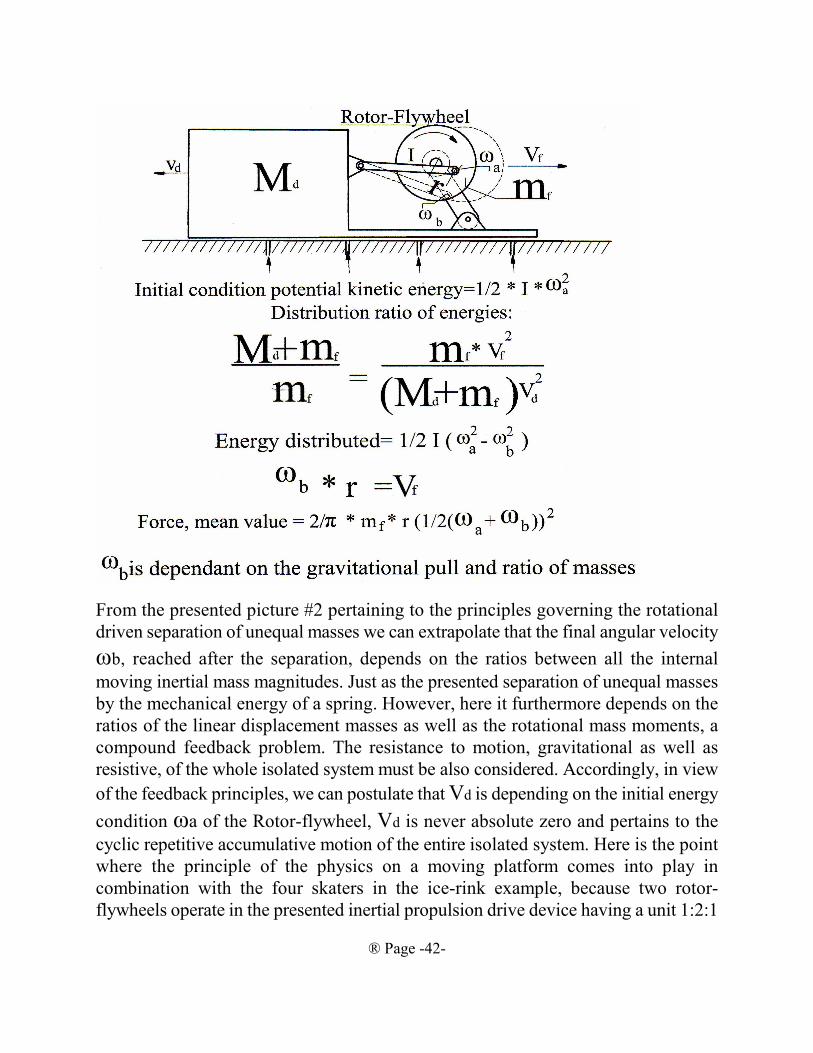
® Page -42-
From the presented picture #2 pertaining to the principles governing the rotational
driven separation of unequal masses we can extrapolate that the final angular velocity
ωb, reached after the separation, depends on the ratios between all the internal
moving inertial mass magnitudes. Just as the presented separation of unequal masses
by the mechanical energy of a spring. However, here it furthermore depends on the
ratios of the linear displacement masses as well as the rotational mass moments, a
compound feedback problem. The resistance to motion, gravitational as well as
resistive, of the whole isolated system must be also considered. Accordingly, in view
of the feedback principles, we can postulate that Vd is depending on the initial energy
condition ωa of the Rotor-flywheel, Vd is never absolute zero and pertains to the
cyclic repetitive accumulative motion of the entire isolated system. Here is the point
where the principle of the physics on a moving platform comes into play in
combination with the four skaters in the ice-rink example, because two rotor-
flywheels operate in the presented inertial propulsion drive device having a unit 1:2:1
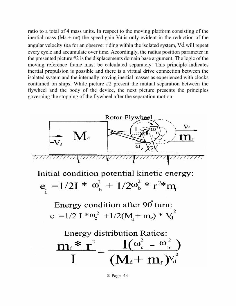
® Page -43-
ratio to a total of 4 mass units. In respect to the moving platform consisting of the
inertial mass (Md + mf) the speed gain Vd is only evident in the reduction of the
angular velocity ωa for an observer riding within the isolated system, Vd will repeat
every cycle and accumulate over time. Accordingly, the radius position parameter in
the presented picture #2 is the displacements domain base argument. The logic of the
moving reference frame must be calculated separately. This principle indicates
inertial propulsion is possible and there is a virtual drive connection between the
isolated system and the internally moving inertial masses as experienced with clocks
contained on ships. While picture #2 present the mutual separation between the
flywheel and the body of the device, the next picture presents the principles
governing the stopping of the flywheel after the separation motion:
® Page -44-
Within the previous picture #3 it becomes apparent that there are slightly
different principles involved between the mutual separation and the stopping of the
flywheel - rotor linear displacement inertial mass motion. The base principle,
however, is in both cases the distribution or the conservation of the root cause
potential mechanical energy between all the inertial mass magnitudes in motion. The
rotating moment exerted onto the friction- less table are negated to a sum of zero by
a second flywheel- rotor operating in opposite rotation direction present on mass M.
The presented Physics principles lead us then to postulate, that for the combined
rotational and linear displacement coupled inertial propulsion drive an optimization
process is necessary to arrive at the maximum possible drive efficiency by arranging
the device mass ratios such that ωb and ωc are the smallest possible magnitudes
when extracted from the moment of inertia of the rotor- flywheel at ωa. When the
mass ratios are optimized +Vd is significant larger then -Vd, this is because +Vd is
removing kinetic energy from the ωa potential mechanical energy magnitude
thereby creating a natural internal self contained impulse. The formulas for the
angular velocity ωb and ωc will be developed in the proof section of the publication
to proof a self contained impulse is being exerted. These formulas, however, are not
presented in the average Physics text-book for Engineers and Scientists?
From the principles presented in picture #2 and #3 we can further extrapolate
that in case the kinetic energy storage capacity of the rotor measured in mass
moments I matches the kinetic storage capacity of the coupled linear displacement
motion m r² inertial mass we can say the device has resonant condition of maximum
energy flow. This resonant condition principle is congruent with an electrical coil -
capacitor series connection resonant condition having maximum current flow and
minimum impedance. However, this resonant condition of matching rotational to
linear kinetic energy storage capacity is not the same as the linear displacement spring
mass motion oscillator resonant condition because the total stored kinetic energy of
the rotational to linear coupled oscillator can have theoretically any kinetic energy
magnitude. The flow of kinetic energy between the rotor and the linear motion inertial
mass has, because of the law of kinetic energy conservation, an important
consequence: The angular velocity of the rotor ωa varies up and down in magnitude
with the kinetic energy demand of the reciprocating inertial mass motion, which
ought to be accounted for in the textbook formulas #1-#7. The ratios of the squared
angular velocities are equal to the ratio of the rotor moments of inertia relating to the
projected reciprocating mass inertia +1. This “plus one” indicates this is a feedback
® Page -45-
principle formula. This formula will be developed, presented and exhaustively proven
in the body of the publication.
The author was unable to find a postulated reason why the angular velocity
variation of the crank rotor is not accounted for in the garden verity of physics
textbooks, not withstanding the usual footnote that the presented formulas apply only
to harmonious sinusoidal motion. In which case it is complying with Newton’s
impulse/momentum/acceleration mass motion. Because, when the rotational to linear
coupled motion is harmonious then the cyclic velocity gain and the cycle time have
uniformity with the average motivating force; F=m*Velocity, gain / time, cycle.
When the mass of the crank rotor is very large and is driven by a large RPM regulated
motor then the angular velocity variance of the crank rotor caused by the energy
demand of the cyclic linear mass motion is indeed near zero, but never absolute zero.
However, in case of the presented IP drive the crank rotor/cam has a small mass
moment in comparison to its linear displacement inertial mass reluctance, further is
having a very high average angular speed, high variations in angular speed and high
variation in kinetic energy where a formula taking the crank rotor kinetic energy
variations into account is an absolute necessity to describe its physics properties
properly. To separate harmonious Newtonian sinusoidal mass motion from
Non-harmonious mass motion we categorize the non-harmonious into the vibrations
category where a formula reappear filed under Non-uniform circular motion.
Non-uniform circular motion is usually presented together with Non-uniform linear
mass motion in advanced physics courses, a subject for the elite physicists. This
strange physics filing system is a further incongruence of mass motion physics. Why
not present uniform circular motion with Non-uniform circular motion in all
university caliber physics textbooks together? The presented inertial propulsion
mechanical rotational to linear mass motion oscillator having a tiny rotor moment of
inertia matched with a massive linear mass reluctance is having the largest possible
phase shift and the largest possible non-uniform angular circular motion. This
principle of phase shift of potential energy to effective energy depending on the
unbalance of the reluctance working in the complex Cartesian grid is a universal
principal in physics, applying also to electrical capacitor / coil oscillators. The kinetic
energy depletion of the crank rotor does not need necessarily to be only attributed to
the energy consumption by the linear accelerating mass. Kinetic energy can be
withdrawn with an additional flywheel on the same axis as the crank rotor, the results
to the coupled motion are identical. This kinetic energy withdrawal principle is
sometimes referred to in publications as interferences causing the mass motion
® Page -46-
becoming frequency modulated. With this relationship we need to look at Newtonian
linear mass motion again where the mass is gaining velocity magnitude uniformly
with the force applied force=m*a. Double the force obtains twice the acceleration!
Does Newtonian linear mass motion Force=mass*acceleration account for kinetic
energy depletion as present in the rotation to linear coupled motion? As we have seen
in the Gyro Bus and Trebuchet example, here again, the analysis cannot depend on
the impulse to momentum relationship but depends on the kinetic energy relationship
because of kinetic energy transfer and depletion. The kinetic energy depletion of an
object, while motivating a second object through a rotational transmission ratio, will
cause the motivating force to follow a complex non-uniform progression in the
complex Cartesian grid. The mass motion uniformity is apparently out of phase or
phase shifted if the crank rotor is having a rapid transfer and depletion of rotor kinetic
energy in an avalanche fashion; the force exerted by the rotor crank is accordingly
diminishing rapidly also in an avalanche fashion and the velocity of the linearly
displacing mass is evolving 90° out of phase with the force. The force is at the
maximum at the beginning of the 1/4 rotation to linear displacement coupled mass
motion having a 90° cycle and the linear displacement mass motion maximum
velocity occurs at the end of the cycle. Accordingly, low angular speed rotating
inertial propulsion systems invariable exhibit an intermittent somewhat walk like
motion. Accordingly, it is un-scientific to confused the intermittent inertial propulsion
motion with reverberation / sticktion / reiterations as it ignores the root cause of
theses motions. The progression of the forces is caused by the energy flow, the
product of force applied over a distance of motion per time interval and considering
equally, energy flow is force multiplied by velocity. This relationship is summarized
and distilled into the universal applicable formula for inertial propulsion where a
collapsing of angular velocity “A” dropping down to angular velocity “B” is
performing the inertial propulsion, then the energy flow magnitude within a cycling
system is:
#8) Energy, Work=½ mass, transferred * radius² * (1/2(ω,a- ω,b))²
The effective Impulse is the Isomorphic symmetry of energy and impulse in the real
effective portion of the complex Cartesian Grid.
#9) Impulse = mass, transferred * radius * (1/2(ω,a- ω,b)) These final formulas are in the complex Cartesian grid and are universally
applicable to all IP systems including the authors Single Impulse Education Device.
This formula can be verified and compared with formula #7 and it will be shown in
the body of the publication that both formulas provide a good accuracy for the
® Page -47-
calculation of the propulsion impulse. Formula #7 must be modified to calculate the
NET impulse using the linear displacement to rotation transfer mass motion A and B
as the calculation approximation where we arrive at:#10: Impulse=////2*mass,transfer*Speed,gain,repeating*(////Speed,average,A-////Speed,average, B)
From here, we can postulate with certainty, the resulting self contained
impulse is the same for formula #9 and #10. Apparently the principle of inertial
propulsion emerges as viable from these formulas when we consider that rotational
momentum has been proven to be also consistent with flow considerations by
professor Herrmann and Schmidt at the University of Karlsruhe and that the Inertial
Propulsion technology is afer all related to the Gyrobus technology and not related
to pushing bowling ball straight down the bowling ally. Importantly: The frequency
modulated cyclic mass motion is a rotational accelerated/de-accelerated mass motion
because of the rotational source and sink of the kinetic energy. The presented IP drive
uses rotational de-acceleration as its source of propulsion impulse. This principle
must be viewed as the same as breaking a car in a steep curve where kinetic energy
is removed. Because the linear mass motion is following and caused by the rotational
motion. The method of how the car is breaking does not matter, only the fact that it
slows down will generates complex vector forces. Hopefully, the reader has
experienced the strange forces at play during the curve breaking action. This action
is counter intuitive because the linear break de-acceleration force is actually
momentarily adding to the car’s present centripetal force BEFORE a reduced car
speed is reducing the centripetal force! A very important aspect of car driving and
also in physics. Whenever an apparent phenomena in non intuitive we used to assign
it to magic. Of course this phenomena is explained with the complex plane math, a
sort of imaginary magic working with imaginary numbers and a mouthful to
comprehend. The complex number arises because we cannot rationally say the quare
root out of -1 is actually producing a negative number:
////-1
The complex operator in formula #10 is the ////-speed, average, B. The
manifestation of complex vectors forces at play having complex operators, is
that’s why non-uniform mass motion is taught in advance physics courses?
The fact that rotational to linear displacement coupled inertial mass motion
vectors operates in a complex Cartesian grid plane should come as no surprise
as it presents the general physics symmetries for reluctance found also in
electrodynamics of coils/capacitors, electrical AC system power factors,
apparent to real power ratio of electrical motors and transformers etc. Already
predicted by Heinrich Hertz in his book. All these phenomena are caused by the
® Page -48-
amount of cycling energy within the oscillating systems, which contributes to
the stress-load of the oscillator but does not contribute to the real domain output
of the oscillator until the oscillation collapses. A temporary increase in the
stored energy flow, the imaginary energy within the cycling system, will cause
an increase in the magnitude of the real power loss vector component because
the imaginary circulating energy flow is in fact also energy, they are cycling
electrons and most importantly is also force times distance and will cause an
increase of work in a series connected load in the real plane vector if the
oscillation suddenly collapses. Are there known products that is using the
collapsing rotational complex Cartesian grid system? The first one comes to
mind is the collapsing electro-dynamic field causing large energy sparks, but the
most important one are the switching power supplies used in computer, where
tiny coils produce thousands of watt of power. The publication can therefore
postulate: The presented IP drive is made possible because of the complex
vector nature of non-harmonious frequency modulated rotational to linear
coupled inertial mass motion. This principle will be presented in the propulsion
cycle description and proven to exhaustion in the proof section of the
publication including the author’s logical provable formula #8.#9 and #10.
Here again, similar to the conveyor, the intensity of the power flow is depending
on the time duration of the cyclic motion because the angular rotor/crank
velocity is also 2 * π / (time, cycle). The rotational cycle time, in union with the
mass, is presenting the magnitude of the available energy and the cause, which
is effecting the magnitude of the reciprocating power flow. How can we present
all this intricate physics talk into a description easily digestible by an average
human being? Lets plot the average centrifugal / centripetal forces and the
average linear displacement impulses within a rotational to linear displacement
mechanism in picture #3. It reveals that the force is outrunning / outperforming
the rotational speed: Double the speed gives quadruple the force. While the
linear impulse is proportional to the rotational speed. The useful range in
rotational speed variation is a total variation of 33% up and down from the
average speed. This means that the higher the average linear displacement speed
the higher the net impulse range magnitude. Furthermore, it reveals that the
mass * radius * ½(ωa+ωb) is the average impulse exerted. This is an universal
principle in physics and it will be proven that it also holds true for a non-uniform
rotational motion. Lets got to picture #4 in the next page:
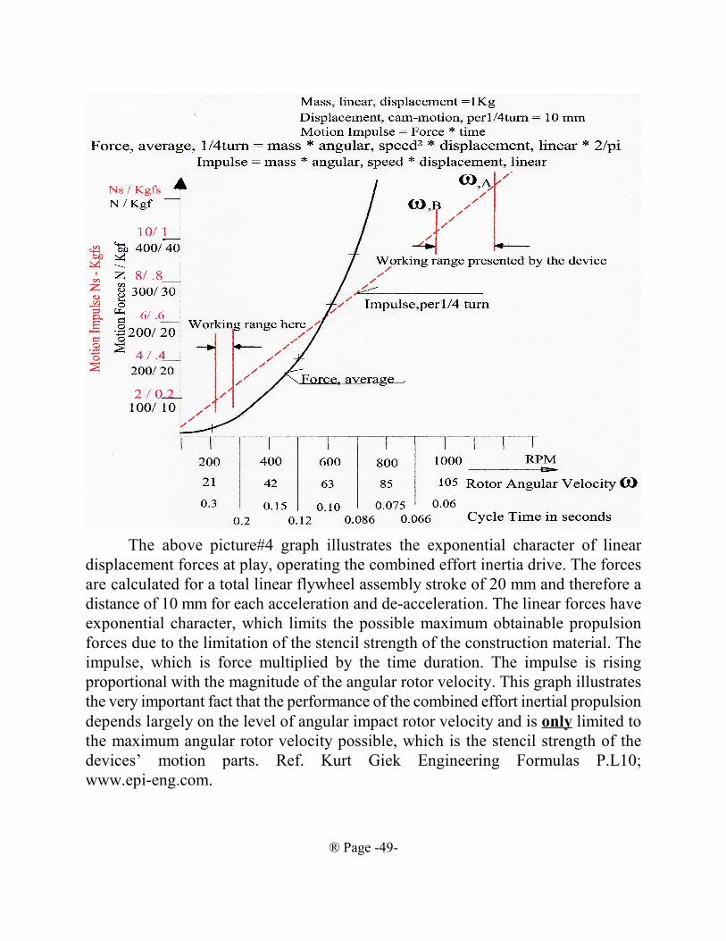
® Page -49-
The above picture#4 graph illustrates the exponential character of linear
displacement forces at play, operating the combined effort inertia drive. The forces
are calculated for a total linear flywheel assembly stroke of 20 mm and therefore a
distance of 10 mm for each acceleration and de-acceleration. The linear forces have
exponential character, which limits the possible maximum obtainable propulsion
forces due to the limitation of the stencil strength of the construction material. The
impulse, which is force multiplied by the time duration. The impulse is rising
proportional with the magnitude of the angular rotor velocity. This graph illustrates
the very important fact that the performance of the combined effort inertial propulsion
depends largely on the level of angular impact rotor velocity and is only limited to
the maximum angular rotor velocity possible, which is the stencil strength of the
devices’ motion parts. Ref. Kurt Giek Engineering Formulas P.L10;
www.epi-eng.com.
® Page -50-
Then it can be postulated with certainty:
The larger the average angular rotor velocity and the larger rotor
angular rotational frequency modulation the larger is the propulsion
thrust in a diminishing returns progression.Then, of course, the argument contrary to IP is raised. Using the law of mean
value, the angular velocity multiplied by the crank radius is the linear motion velocity
gain, then divided by the cycle time is the mean value linear displacement force
applied by the cyclic motion. The motivating force is then the same as the resultant
force from the subsequent reactive impulse. Is Newton’s equal reaction to an action
shutting IP down? NO, this argument is not shutting down the inertial propulsion
show,because the presented inertial propulsion is using a non-harmonious cyclic mass
motion transmitted through a transmission ratio having a frequency modulated
variable cycle time, non-uniform crank rotor circular motion and an average angular
velocity keeping the cyclic velocity gain of the sinusoidal linear displacement
magnitude IN-variable and the cycle time VARIABLE, therefore the propulsion force
is an exponential variable parameter outperforming -outrunning the non-uniform
changes in cycle time. The INVARIABLE linear displacement transfer mass motion
velocity gain of the crank rotor, when reduced by the relative velocity gain of the
whole aggregate mass of the vehicles’ moving reference frame is making the cyclic
reactive impulses within the vehicles’ frame of reference invariable, then the
exponential motivating force is still outperforming-outrunning the reduction in
transfer mass linear displacement velocity gain propelling the vehicle forward. The
underlying principle/reason is again the closed loop energy feedback described by the
basic feedback formula:
Output, from, feedback = Input, into, feedback / (1 + Transfer. function)
Reference: Kurt Geeck, section T9
The “Transfer, function” is a sum/ratio of the vehicles’ aggregate inertial mass
to the flywheel inertial mass. This means the IP energy drive output into the aggregate
vehicle mass can NEVER be absolute ZERO as long as the cyclic rotor initial Input
energy potential is superior and as long as the superior rotor kinetic energy is
acquired independently to the vehicles’ aggregate inertial mass. This principle of a
distributed energy magnitude in spite of a relative reduced linear velocity cause by
the moving reference frames of the vehicles’ aggregate inertial mass will be proven
in the proof/math section of the publication. Then, frequency modulated rotational to
linear coupled mass motion is incongruent with the impulse formula and the impulse
formula: impulse = mass * Velocity, gain; Does not apply to rotational/linear coupled
motion in the complex plane rotation. This is because the accumulated sum of each

® Page -51-
individual prevailing force within the propulsion cycle is the sum of each fractional
motion momentary rotational tangential vector forces:
Force,vector,centripetal = mass * Velocity² ,tangential, momentary / Radius.
Furthermore:
Velocity², tangential / Radius, crank = Velocity², angular * radius, crank
The tangential rotational velocity vector within the frequency modulated
angular motion has an up to 50% magnitudes gradient, this means a more than 200%
gradient in the centripetal force vector. For example 1.5 is 50% more then 1. Hence
1.5²= 2.25, a 225% increase over 1. This principle will be further proven in the proof
section and is illustrated with a mass motion contour Graph and proven with a
comprehensive IP formula. From this numeric examples it can be postulated:
Non-uniform rotational to outrun-outperform the reduction in the time parameter
resulting in a uniform linear displacement coupled mass motion makes the forces
relationship of average angular speed magnitude to average impulse magnitude. Then
the argument contrary the presented IP system continues because the impulse applied
to accomplish the frequency modulation is CONSIDERED to be exactly the same as
the gain in any self contained driving propulsion impulse. No, this argument is not
the fact, because: The presented IP system applies short, powerful and progressively
increasing frequency modulation impulses during the declining and the least
magnitude of the liner displacement mass motion velocity, during the peak magnitude
of the angular velocity of the cyclic sequence, reciprocally and radial exerted against
a SECOND FREE WHEELING FLYWHEEL! The modulation impulses are therefore
generating themselves new larger instantaneous complex plane centripetal forces
applying the same linear reaction impulses as the action of the frequency modulation
impulse. Consequently, at the end of the frequency modulation impulse duration, this
is generating an exponential gain in crank/cam rotor independent rotational kinetic
energy without adding net additional linear displacement reactionary impulse because
of Newton’s equal reaction to an action. Then, furthermore, the “Coriolis Force” is
being questioned: Perhaps the Coriolis force is contrary to the centripetal force and
canceling all net forces. No, this is not the case because the flywheel rotor and the
rotational to linear displacement coupled transmission is a balanced system, where
only the Huygens- Steiner parallel axis theorem singularly causing the internal self
contained impulses as presented already with the modified trebuchet example.
A final argument is raised by the method of the modulating impulse in
comparison the net gain in self contained motivating impulse: Why is the linear
vector portion of the modulating impulse, during the declining and least magnitude
of cyclic linear motion velocity (picture#3), not the same as the net self contained
® Page -52-
linear driving impulse during the expanding cyclic linear mass motion velocity
(picture#2)? This is because the declining cyclic linear displacement mass motion
velocity is a kinetic energy conserving (combining) motion while the cyclic
expanding velocity linear displacement mass motion is a kinetic energy distributing
mass motion, distributing an exponential higher motivating kinetic energy quantity
and higher curve breaking vector and therefore a higher complex vector sum
magnitude of centripetal force and consequently a higher unidirectional
self-contained net impulse.
ALL arguments contrary to the presented IP system are thereby truly
exhausted.
With all the presented facts it is certain Inertial Propulsion does exist,
furthermore the accumulation of masses as seen with the linear displacement
conveyor is solved with the combined rotational to linear displacement IP system.
However, what energy efficiency can be expected by analyzing the presented
formulas and the presented Inertial Propulsion Education Device? For every 1 kgf
meter of cyclic oscillator energy circulation which comprises a 1 meter long ideal
spring compressed by the weight of a 1 kg mass is approximately only able to
generate 0.02 kgf seconds or 0.20 Newton seconds of self contained impulse. This is
about the impulse of throwing a $ 2 CD coin (the Two-nie coin) as hard as all
possible into a piggy-bank. Indeed, a large amount of stored energy circulation in
form of very high RPM speeds, and extremely energetic short duration modulating
pulses are required to accomplish a viable IP drive. No, a viable Inertial Propulsion
Drive can not be build with any old furnace motor. This illustrates the technological
challenges to demonstrate the generated product of self contained force and time
duration with the required pendulum test operating within the gravitational field of
almost 10 meter/s², the only test the science community accepts as valid. But, then
again, what exquisite technology have we accumulated to lift our space station into
Earth Orbit?
To positively illustrate the exceedingly complex IP drive principle of frequency
modulated cyclic mass motion having a complex cyclic logic we present the typical
cyclic mass motion contour graph in 1/5 cycle time-rotation increments wherein a 90º
rotor rotation is having alternating a 1/5 and 3/10 of the cycle time duration with
equal area under the displacement speed curve, plotted in the time domain.(picture
#5):
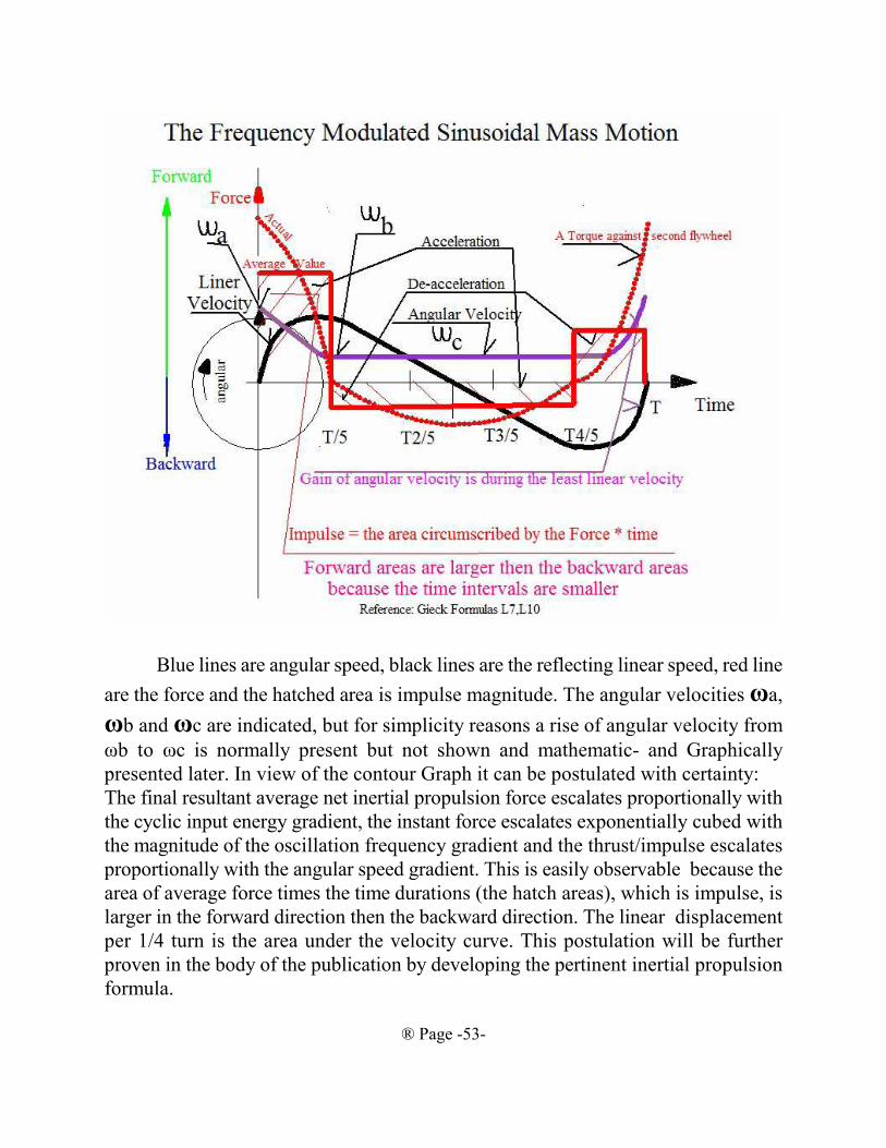
® Page -53-
Blue lines are angular speed, black lines are the reflecting linear speed, red line
are the force and the hatched area is impulse magnitude. The angular velocities ωa,
ωb and ωc are indicated, but for simplicity reasons a rise of angular velocity from
ωb to ωc is normally present but not shown and mathematic- and Graphically
presented later. In view of the contour Graph it can be postulated with certainty:
The final resultant average net inertial propulsion force escalates proportionally with
the cyclic input energy gradient, the instant force escalates exponentially cubed with
the magnitude of the oscillation frequency gradient and the thrust/impulse escalates
proportionally with the angular speed gradient. This is easily observable because the
area of average force times the time durations (the hatch areas), which is impulse, is
larger in the forward direction then the backward direction. The linear displacement
per 1/4 turn is the area under the velocity curve. This postulation will be further
proven in the body of the publication by developing the pertinent inertial propulsion
formula.

® Page -54-