or strong coupling have been produced - nist · radiation whose beam waist was varied between 5 and...
TRANSCRIPT

26 1
S.L. Gilbert, J.C. Bergquist, J.J. Bollinger, W.M. Itano, and D . J . Wineland
National Bureau of Standards, Boulder, CO 80303
ABSTRACT Experiments on collections of strongly coupled laser cooled atomic ions performed at the National Bureau of Standards are summarized. We first discuss strong coupling of small numbers ( 5 20) of atomic ions zonfined in a Paul electrodynamic (rf) trap, in which crystalline structures are observed. We then discuss experiments in which shell structure is observed for up to 15 000 ions confined by static electric and magnetic fields. These clouds display liquid and solid-like behavior siqilar to that of a smectic liquid crystal. Future experiments are suggested. including scme where infinite volume behavior nay be observable.
1. I N T R o m o N
Strong coupling in collections of charged particles occurs when :he Coulomb interaction energy between nearest neighbors is larger than their respective thermal energies. Particles in such a system can display spatial ordering characteristic of liquid and solid Phases.
Paper of Malmberg and O’Neill who discussed the possibility of 3chieving liquid and solid-like behavior in a pure electron plasm
“-onfined in a Penning trap.
zoupling condition could be achieved in a sample of laser cooled ions.
Our interest in this field was in part stimulated by a 1977
It seemed possible to us that the strong
Although the conditions €or strong coupling have been produced - ions2e3 and electrons4 confined in Penning traps, evidence for

262 S. L. Gilbert er 01.
spatial ordering was not obtained until recently.
will discuss the observation of crystalline cluster^^*^ and shell In this paper we
structures7 in laser cooled, trapped ion clouds.
Strong coupling in Coulomb systems is of interest in several fields of physics and is expected to give rise to a variety of many- body phenomena.8
strong coupling has been observed in small numbers (S 100) of macroscopic charged particles confined in a rf trapY9 configurations of electrons near the surface of liquid helium, lo and
charged particles in liquid suspension which act through a shielded Coulomb potential. Future possibilities for observation include
ordering of particles confined in high energy storage rings.
a trap are identical to t hose of a one-component plasma (OCP).l*'
OCP consists of a single species of charged particles embedded in a uniform-density background of opposite charge. ions in a trap, the trapping fields play the role of the neutralizing background charge. An OCP can be characterized by the Coulomb coupling constant, 1 9 8
In addition to the ion trap work described here,
2D
12
The static thermodynamic properties of an ion cloud confined in
An
For the system of
which IS a measure of the nearest neighbor Coulomb energy divided by
the thermal energy of a particle. charge and temperature.
4Tas3n0/3 = 1, where -qno is the charge density of the neutralizing background.
The quantities q and T are the ion The Wigner-Seitz radius as is defined by
An infinitely large OCP is predicted8 t o exhibit liquid-like behavior (short range order) for r > 2 and have a liquid-solid phase
transition to a body-centered cubic (bcc) lattice at r 5 178.
following sections we will describe vork at the National Bureau of
Standards (NBS) on strong coupling of atomic ions confined in rf and Penning traps.
was greatly influenced by the boundary conditions imposed on the
In the
The spatial ordering observed in these experiments
LlQUlD AND SOLID PHASES OF LASER COOLED IONS 263
clouds due to the trapping fields. In the last section, we will discuss future experiments in which the infinite volume bcc lattice
may be observed.
2. UXJUXfl "WTKRS" IN A Rp TRAP (I 20 IONS) With the practical density and charge limitations imposed on
atomic ions in electromagnetic traps, very low temperatures must be realized in order to obtain r >> 1. This has been achieved by laser
cooling. A
similar experiment has been performed on Mg' ions at the Max Planck
Institute for Quantum Optics in Garching.6
Here we describe an experiment using Hg' ions at NBS.5
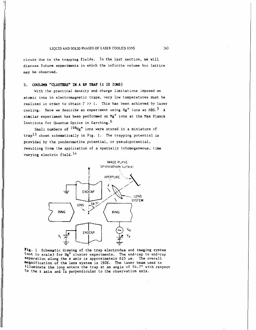
Small numbers of lg8Hg+ ions were stored in a miniature rf trap13 shown schematically in Fig. 1. provided by the ponderomotive potential, or pseudopotential,
resulting from the application of a spatially inhomogeneous, time
varying electric field.
The trapping potential is
14
IMAGE PLANE (photocathode surface;
t i
I
LENS SYSTEM
Fig. 1 (not to scale) for Hg+ cluster experiments. Separation along the z axis is approximately 625 m. The overall magnification of the lens system is 180X. The laser beam used to illuminate the ions enters the trap at an angle of 54.7' with respect to the z axis and is perpendicular to the observation axis.
Schematic drawing of the trap electrodes and imaging system The end-cap to end-cap

radiation whose beam waist was varied between 5 and 15 pm at the
position of the ions.
5d1°6p 2Pf resonance line. ions was focused onto the photocathode of a resistive-anode photon-
counting imaging tube as shown in Fig. 1.
‘was provided by a three-stage fused-quartz lens system with an
aberration-compensated first stage. The first lens w a s apertured to
give an f number of 4 . 5 .
the imaging tube could be displayed on an oscilloscope in real time or stored by a computer in order to make time exposures.
This radiation was tuned near the 5d1°6, 254 +
Some of the 194 run fluorescence from the
The optics for the imaging
The positions of the photons detected by
In Fig. 2a we show the orientation of the trap as viewed by the imaging tube. The remainder of Fig. 2 shows images obtained for
various numbers ( 5 16) of ions. Below the images in Figs. 2d through g, are the configurations obtained theoreti~ally’~ by minimizing the
energy for each value of the number of ions Ni for a given trapping potential.
circulation about the z axis. The number of ions could be assigned by stretching the ions out along the z axis, as in Pig. 2c, or by
varying the trapping parameters (VAC and VR in Fig. 1) and comparing the observed images with the simulations.
The rings in Figs . 2e through g are due to ion
Although the trap was designed to have axial symmetry, there is
apparently a small asymmetry which caused the ions in 2b to align along the x axis. This pinning also occurred in 2d due to the extra
asynawtry of an impurity ion. In the experiments of Ref. 6, the trap
asymmetry in the x-y plane was apparently larger than observed here
and caused pinning of like ions under a wide variety of conditions- These clusters of atomic ions can be viewed as pseudomolecules
whose optical spectra would be expected to shov rovibronic structure*
We have measured the mode structure of the diatomic pseudomolecule (Hg+>2 by probing its optical struct~re.~
the spectrum of the 2S1/2(mJ = +1/2) + 2Dg/2(m~ = -1/2) electric
quadrupole transition ( A
the sidebands due to the stretch and rocking motions of the ions.
This was done by measuring
282 nm) of one of these ions and obsefling

LIQUID AND SOLID PHASES OF LASER COOLED IONS
ion cluster
( f )
iv; = 9
x (b)
.vi = 2
265
ig. 2 lectrodes are shown schematically in the same orientation as for the mainder of the pictures, but at reduced magnification. The oordinate system in (b) applies to the rest of the images. icks on the axes are 10 pm from the origin. isplay numerical solutions for the expected cluster shapes using the xperimental value of the trapping potential. In ( d ) , a onfluorescing impurity ion occupies one of the ion sites in the luster and helps pin the ions in the radial plane.
Images of Hg' ion "clusters" in a rf trap. In (a), the trap
The In (d) through ( g ) , we

266 S. L. Gilbert et a1
F i n a l l y , i n Fig. 2g we see t h a t 16 ions appear t o lie on 3 rings. The larger ring, containing 8 ions, lies near the x-y plane and the smaller rings, each containing 4 ions, lie in planes above
and below but parallel to the x-y plane. We may also view these ions
as lying on the surface of a spheroidal shell characteristic of the structure for large numbers of ions.l6-l8
possible to observe ordered structures of much larger numbers of atomic ions in rf traps. In our trap, this was difficult for N i t 2 0 because the small amount of power available for cooling was unable to
overcome the rf heating."
ion's driven motion (at the trapping field frequency) is coupled into the secular motion characteristic of the pseudopotential well.
In principle, it should be
In rf heating, the kinetic energy of the
3. SBELL STRUCTURR PFfASE M A Pl?XNRG TRAP ( S 15 000 IONS)
In Penning traps,14 where ions are confined by static electric and magnetic fields, rf heating does not take place and large
collections of ions can be cooled to temperatures less than 10 mK.
"his larger system is closer to the conditions of an infiriite volume
plasma and should display a rich variety of phenomena.
The boundary conditions are still expected to have a significant
effect on the state of a finite plasma consisting of a hundred to a few thousand ions. Molecular-dynamics simulations involving these
numbers of ions have been done for the conditions of a spherical16-18 and spheroidal2'P2' trap potential. Instead of a sharp phase
transition to a bcc lattice, the simulations predict that the plasm w i l l separate into concentric, nearly spheroidal shells (due to the
shape of the trap potential) which gradually become more pronounced as increases. These shells are one ion thick, and the distance
between ions on the surface of a shell is predicted to be approximately equal to the shell separation. prediction is that there should be a range of conditions where the ions will behave like a liquid within a shell (short range order " diffusion) and a solid across shells (no diffusion between shells) "his characteristic is similar to some phases of smectic liquid
Another interesting
th 18

LIQUID AND SOLID PHASES OF LASER COOLED IONS 267
crystals.22 to form on the outer shells.18
At higher r a distorted 2D hexagonal lattice is expected
We have investigated this system using 9Be+ ions trapped in the cylindrical Penning trap shovn schematically in Fig. 3 . A magnetic
field B = BS (B = 1.92 T) produced by a superconducting magnet confined the ions in the direction perpendicular to the z axis. A
static potential Vo between the end and central cylinders confined the ions in the z direction to a region near the center of the trap.
The dimensions of the trap electrodes were chosen so that the first anharmonic term of the trapping potential was zero.
near the trap center, the electric field potential can be expressed (in cylindrical coordinates) as @
-.
Over the region
AV0(2z2 - r2>, where A = 0.146
This potential, when combined with the magnetic field, forces
the cloud into a spheroidal ~ h a p e . ~ . ~
is superimposed on a uniform rotation of the due to BxB drift, vhere f is the electric field due to the trap voltage and the space charge of the ions.
The ions' thermal distribution
(frequency W ) --A
The ions were laser cooled and optically pumped into the 2s 2S1/2(M~=3/?,M~1/2) state by driving the 2s 'S1/2(3/2,1/2) +
2p 2P-,~2(3/2,3/2) transition slightly belov the resonant freq~ency.~*~
directed perpendicular to the magnetic field and/or along a diagonal
as indicated in Fig. 3 . In addition to cooling the ions, the laser also applied an overa l l torque which would either compress or expand
the c l o ~ d . ~ * ~
radial positions (and thus the torques) of the perpendicular and
diagonal beams.
The 313 nm cooling radiation ( = 30 pW) could be
We controlled the size of the cloud by choosing the
About 0.04% of the 313 nm fluorescence from the decay of the 'P3/2 state was focused by f/10 optics onto the photocathode of the same imaging tube used in the Hg' experiments. .ocated along the z axis, about 1 m from the ions. The imaging
>ptics was composed of a three stage lens system with overall iagnification of 27 and a resolution limit (FWHM) of about 5 um.
The imager vas
O u n t rates
~
ranged from 2 to 15 kHz.

268 S. L. Gilbert er al.
IMAGER LENS PROBE SYSTEM BEAM ,
PER PEN DICULAR ' DIAGONAL COOLING BEAM COOLING BEAM
Fig. 3 Schematic drawing of the trap electrodes, laser beams, and imaging system (not to scale) for the Penning trap experiment. The overall length of the trap is 10.2 cm. The trap consists of two end cylinders and tuo electrically connected central cylinders with 2.5 cm inner diameters. Ion clouds are typically less than 1 m both in diameter and axial length. The diagonal cooling beam crosses the cloud at an angle of 51° with respect to the z axis.
A second laser (power = 1 IJW, beam waist z 30 pm) was used to
spatially map the shell structure of the cloud. This probe laser was
tuned to the same transition as the cooling laser and was directed
through the cloud perpendicularly to the magnetic field. With the probe laser on continuously, the cooling laser could be chopped at 1 kHz and the image signal integrated on ly uhen the cooling laser was off.
the probe beam, in a calibrated fashion, either parallel or
perpendicular to the z axis. fluorescence of all three laser beams.
Different portions of the cloud could be imaged by translating
Images were also obtained from the ion
The probe beam was also used to measure the cloud rotation
frequency w and the ion temperature. probe laser uas tuned to a transition which optically pumped the io-
out of the 2S,/2(3/2,1/2) l e ~ e l . ~ * ~ the fluorescence from the cooling laser beams as the probe laser was scanned through the "depopulation" transition. We determined by
measuring the change in the Doppler shift of the depopulation Signa1 as the probe beam was translated perpendicularly to the z axis. The density no could then be calc~lated~,~ from no = mw(Q - w)/(2Tq2)
For these measurements, the
This resulted in a decrease in

LIQUID AND SOLID PHASES OF LASER COOLED IONS 269
where Q * qB/mc is the cyclotron frequency. With the use of "0 and the cloud size obtained from probe beam images, the total number of
ions was calculated.
Doppler broadening contribution to the spectral width of the
depopulation ~ i g n a l . ~ , ~
and the density, r was calculated using Eq. (I).
The ion temperature was derived from the
From the measured values of the temperature
We have observed shell structure in clouds containing as few as
20 ions (1 shell) and in clouds containing up to about 15 000 ions (16 shells).' Images covering this range are shown in Fig. 4 . We
measured the coupling constant r for several clouds containing about 1000 ions. Possible drifts in the system parameters were checked by
verifying that the same images were obtained before and after the
cloud rotation frequency and ion temperatures were measured.
DIAGONAL COOLING
# ) ? 4 0 t - P R O B E
PERPENDICULAR COOLING
4 Images of shell structures. (a) A single shell in a cloud Containing approximately 20 ions. fluorescence only) in a cloud containing about 15 000 ions. llava shells plus a center column in the same cloud as (b), with lover trap voltage.
(b) Sixteen shells (probe beam ion (C)
This image shows the ion fluorescence from all laser beams. Integration times were about 100 seconds.

270 S. L. Gilberr et al.
Fig. 5 ion cloud with corresponding probe beam images $above). r = 180 ","o (T = 6 !: mK, n8 (T = 33::: mK, no = 2 x 10 ions The clouds contained about 1000 ions in both cases.
Intensity plots along the x axis through the center of the
7 x lo7 ions cm- 1. (a)
(b) r = 50 I%
Figure 5 shows examples of shell structures at two different The first image is an example of high coupling ( r = values of I-.
180) shoving very good shell definition in an intensity plot across
the cloud. The second image is an example of lower coupling ( r = 50)
and xas obtained by only cooling perpendicular to the magnetic field. Variations in peak intensities equidistant from the z axis are due to signal-to-noise limitations and imperfect alignment between the x
axis and the probe beam.
We obtained three dimensional information on the shell structure by moving the probe beam to obtain images at different z positions. We found that there were two types of shell structure present under
different circumstances. the ends of the cloud, indicating that the shells may have been
closed spheroids. Shell closure was difficult to verify due to lack
of sharp images near the ends of the cloud where the curvature was greatest.
the axial width of the probe beam.
structure, it was clear that the shells were concentric cylinders
The first type showed shell curvature near
This was, in part, due to the averaging of the shells Over In the other type of shell

LIQUID AND SOLID PHASES OF LASER COOLED IONS 271
I
zp Gm> 0
-15
-40
- 65
-90
-1 15
- 1 40 -152 - 1 65 -1 78
Fig. 6 Data showing evidence for concentric cylindrical shells. On the right is a series of images obtained with the probe beam for different z positions zp of the probe beam (lower half of the cloud only). the left.
Intensity plots for zp = -40 urn and z * -178 wm are shown on The cloud axial length/diameter ratio was about 1.9.
with progressively longer cylinders near the center.
these data is shown in Fig. 6 . Other evidence for cylindrical shells can be obtained from the fact that shells in the diagonal beam images
occur at the same cylindrical radii as those from the perpendicular beams. This can be seen in the three-beam images such as that shown
in Fig. 4(c). configurations have not yet been identified.
An example of
Systematic causes of these two different shell
So far, our discussion has been limited to the static structure
of strongly coupled ion clouds.
dynamical information. For example, ions can be switched off (removed from the cooling cycle) by driving the probe depopulation
transition.
beam, certain parts of the ion cloud were tagged, allowing ion diffusion studies through the movement (or lack of movement) of the
tagged ions.
relatively rapid diffusion ( 2 100 ~ / 0 . 1 s) of ions within a shell
Mher experiments have provided
'
With appropriate positioning of this depopulating laser
In this way we have recently distinguished the

212 S. L. Gilbert et 01,
from the much slower diffusion (several seconds) between shells,
verifying the smectic nature of this interesting form of matter.
plan to do more detailed diffusion studies in the near future. We
At present, it is difficult to make many quantitative comparisons between our data and the simulations. There is
substantial uncertainty in our measurement of t' due to uncertainty in the temperature measurement.
partially limited by the optics. however, is the relationship between the number of shells and the
number of ions. Ni, in a cloud.
(Ni/4)1/3 shells are predicted.16 Fig. 4(b) (Ni 3 15 000) this formula predicts 15.5 shells and we
measured 16.
Also, the spatial resolution is
One comparison which can be made,
For a spherical cloud, approximately For the nearly spherical cloud of
Our data do agree qualitatively with the simulations with the
exception of the observation of open cylinder shell structures as opposed to the predicted closed spheroids. 16-18*20*21 that shear (that is. different rotation frequencies) between the
shells may account f o r this discrepancy.20
could be caused by differential laser torque or the presence of impurity ions.23 rotation frequency does not vary by more than 30% across the cloud.
This is comparable to the limits discussed in Refs. 3 and 23.
It is possible
In our experiment, shear
For the data here, we have determined that the
4. IrtrmpE lQz"m
A number of future experiments will allow us to better
understand strong coupling in ion clouds. expect to have better light collection optics which w i l l yield improved spatial resolution and collection solid angle for the
Penning trap experiment.
more quantitative data on the ion diffusion times and see how the diffusion varies with r. light from strongly coupled ions can possibly be used to study mode structure of ordered ion motion.
by the use of sympathetic cooling23 whereby two ion species are
In the near future. we
With these optics we will be able to obtain
Also, spectrum analysis of the scattered
Both of these studies may be aided

LIQUID AND SOLID PHASES OF LASER COOLED IONS 213
confined simultaneously in the same trap. cooled and by Coulomb interaction cools and maintains the second ion species at constant temperature.
performed on the second ion species.
larger (Ni >> lo5) samples of ions to be cooled. This may permit the
observation of structure characteristic of the infinite volume regime in which a body-centered cubic (bcc) lattice is predicted.8 Detailed
images in the Penning traps are made difficult by the rotation of the cloud which averages over azimuthal angle.
be possible to strobe the laser or detection electronics at a
frequency harmonically related to w, but this requires w to be sufficiently stable.
difficult but perhaps a single strongly fluorescing ion (such as ME+) which is locked onto the rotating lattice (of Be+> could serve as a "beacon" and aid in determining w.
observation of bcc structure is Bragg s~attering.~.~ Correlation functions which are a function of X-y position24 may
8110~ us to extract spatial correlation information.
One ion species is laser
Dynamical studies are then
Increasing the cooling pover in the experiments should allow
In principle, it should
Fluctuations in ion density may make this
Another possible technique for
Also , intensity
At present, the rather large uncertainty in r in the Penning trap experiments comes f rom the uncertainty in our measurement of
tamperatme. Of the optical spectrum is small compared to the radiative, or
mtural broadening. trasitions whose radiative broadening is negligible as in the Hg+
u p % t f m e n t ~ . ~ , ~ ~
trmsitions might be used for this purpose.
This is so because the Doppler broadening contribution
This limitation can be overcome by driving
For Be+ and Mg' ions, tvo-photon stimulated Raman 2
Finally, it would be very useful to study large numbers of WrtiCles in a rf trap. a t ion8 can remain fixed without rotation.
One clear advantage over a Penning trap is For large numbers of
the mechanism of rf heating must be overcome. This may be
uded by using higher laser cooling power, smaller ratios of secular drive frequencies, and insuring that impurity ions are absent.

214 S. L. Gilbcrf cf aL
Acknmledgewmlts
We gratefully acknowledge support from the Office of Naval Research and the Air Force Office of Scientific Research. We also
thank C.E. Wieman and C.S. Weimer for helpful suggestions on the manuscript.
* Work of the U.S. Government, not subject to U.S. copyright.
1.
2.
3.
4.
5.
6.
7.
8.
9.
10.
J.H. Halmberg and T.H. O'Neil, Phys. Rev. Lett.2, 1333 (1977).
J.J. Bollinger and D.J. Wineland, Phys. Rev. Lett. 53, 348 (1984); L.R. Brewer, J.D. Prestage, J.J. Bollinger, and D.J. Wineland, in Strongly Coupled Plasma Physics, edited by P.J. Rogers and H.E. Dewitt (Plenum, New York, 1987), p. 53.
L.R. Brewer, J.D. Prestage, J.J. Bollinger, W.H. Itano, D.J. Larson, and D . J . Wineland, Phys. Rev. A . , in press.
J.H. Halmberg, T.H. O'Neil, A.W. Hpatt, and C.P. Driscoll, in Proceedin@ of the 1984 Sendai Symposium on Plasma Nonlinear Phenomena, edited by N. Sat0 (Tohoku University, Sendai, Japan, 1984), p. 31.
D.J. Wineland, J.C. Bergquist, W.H. Itano, J.J. Bollinger, and C.H. Hanney, Phys. Rev. Lett. 2, 2935 (1987). P. Diedrich, E. Peik. J . H . Chen, W. Quint, and H. Ualther. PhYs. Rev. Lett. 2, 2931 (1987). S.L. Gilbert, J.J. Bollinger, and D.J. Wineland, Phys. Rev. Lett. 60, 2022 (1988). S. Ichimaru, H. Iyetomi, and S. Tanaka, Phys. Rep. 119, 91 (1987) and references therein.
R.P. Wuerker. H. Shelton, and R.V. Langmuir, J. Appl. Phys. %# 342 (1959); D.J. Wineland, W.H. Itano, J.C. Rergquist, S.L. Gilbert, J.J. Bollinger, and P. Ascarrunz, in Nonneutral piaw Physics, edited by C.W. Roberson, Am. Inst. Phys. Conf. Series, 1988, to be published.
See for example: (Peb. , 1987).
A.J. D a b and W.P. Vinen, Physics Today g s 43 A

11.
12.
13.
14.
15.
16.
17. - g-> $ 8 .
LIQUID AND SOLID PHASES OF LASER COOLED IONS 27s
D.J. Aastuen, N.A. Clark, and L.K. Cotter, Phys. Rev. Lett. 57, 1733 (1986); J . M . di Heglio, D . A . Weitz, and P.H. Chaikin, Phys. Rev. Lett. z, 136 (1987); C.A. Murray and D.H. Van Winkle, Phys. Rev. Lett. 2, 1200 (1987). J.P. Schiffer and 0. Poulsen, Europhys. Lett. L, 55 (1986); D. Habs, in Lecture Notes in Physics 296, edited by H. Month and S . Turner, (Springer-Verlag, Berlin, 1988>, p. 310.
J.C. Bergquist, D . J . Wineland, W.H. Itano, H. Hemmati, H.U. Daniel, and G. Leuchs, Phys. Rev. Lett. 55, 1567 (1985). See for example: B.G. Dehmelt, Adv. At. Mol. Phys. 3, 53 (1967) and 2, 109 (1969); D . J . Wineland, W.M. Itano, and R.S. Van Dyck, Jr., Adv. At. Mol. Phys. 19, 135 (1983).
W.H. Itano et. al., to be published; our simulations agree uith independent ones of D.H.E. Dubin (performed on up to 10 ions).
A . Ram and J.P. Schiffer, Phys. Rev. Lett. 2, 1133 (1986); J.P. Schiffer. submitted for publication.
H. Totsuji, in Strongly Coupled Plasma Physics, edited by P.J. Rogers and H.E. Devitt (Plenum, New York, 19871, p . 19.
D.H.B. Dubin and T.H. O'Neil, Phys. Rev. Lett. 60, 511 (1988).
D.A. Church and H.G. Dehmelt. J. Appl. Phys. lo, 3421 (1969); H . G . D e h l t , in Advances in Laser Spectroscopy, edited by P.T. Arecchi, F. Strumia, and E. Walther (Plenum, New York, 1983), p. 153.
J.P. Schiffer, Physics Dept., Univ. of Chicago, Chicago, IL, privata cammnication.
D.H.B. Dubin, Physics Dept., Univ. of California - S a n Diego, La Jolla, u, private cceeunication. P.G. de Gsnnes, The Physics of Liquid Crystals, (Oxford University Press, London, 1974).
D.J. Larson, J.C. Bergquist, J.J. Bollinger, W.H. Ita09 and D.J. wineland, Phys. Rev. Lett. 57, 70 (1986). N-A. Clark, B.J . Ackerson, and A . J. Hurd. Phys. Rev. Lett. so, 1459 (1983).
J-c . Bergquist, W.H. Itmo, and D.J . Wineland, Phys. Rev. A=, 428 (1987). -