orbital motors - img1.wsimg.com
TRANSCRIPT

© Ryan Hydraulics I 2018
~ RYAN HYDRAULICS ~ Solution to Hydraulic System
SHANGHAI RYAN FLUID POWER CO.,LTD
Address: Rm 1703-2, 33#, 1228 Jiangchang Rd, Shanghai, China
Tel: +86-21-56626882
Email: [email protected]
Website: www.ryanhydraulic.com
Zip code: 200434
0
goo
0 0
oO 0 0
~ RYAN HYDRAULICS ~ Solution to Hydraulic System
ORBITAL MOTORS GP/GR/GH/GS/GT/GV/GGM

Keep the concept seeking excellence, Ryan try our best to
create more value for you with products and service.
RYAN HYDRAULICS

www.ryanhydraulic.com01/02
Ryan Hydraulics
9 Series ProductsCovers the Whole Hydraulic BusinessAs a supplier of hydraulics, our business covers: hydraulic motors, hydraulic control valves, hydraulic gear pumps, power units and hydraulic systems, etc. Products are widely used in construction machinery, agricultural machinery, industry equipment.
Supplier of the Whole Hydraulic SystemRyan Hydraulics manufacture was established in 1986, focusing on R&D, manufacture and sales of hydraulic products. Ryan Hydraulics owns world top level R&D team, as well as invention patents, sales covers global market.Targeting at vision of Excellence, Ryan Hydraulics keeps creating more value for customers by quality products, professional technology and experienced service.
645,835 sq.ft Modern ManufactureSince the opening of 3rd generation modern manufacture in 2015, the total area covers 1,291,669 sq.ft, while the construction area covers 645,835 sq.ft, there are IT machining equipment, test and inspection equipment, meets various requirement of global customers.
Instant Efficient ServiceTechnical Team offers accurate solutions to the service, including the product model selection, product test, installa-tion and commissioning, debugging etc., so as to keep in touch with right department of each customer in time and respond to the customer's requirement.
Customer FirstWith leading technology, quality product, and professional service, Ryan Hydraulics has covered the global market with more than 60 countries and regions, become the strategic partner of many international famous OEM enterprises.

Contents
www.ryanhydraulic.com03/04
GP Series Orbital Motors
GPH
Specifications
Function Diagrams
Dimensions and Mounting
Shaft Extension Dimensions
Ordering Code
GR Series Orbital Motors
GRS
Specifications
Function Diagrams
Dimensions and Mounting
Shaft Extension Dimensions
Ordering Code
GH Series Orbital Motors
Specifications
Function Diagrams
Dimensions and Mounting
Shaft Extension Dimensions
Ordering Code
GS Series Orbital Motors
GSS
Specifications
Function Diagrams
Dimensions and Mounting
Shaft Extension Dimensions
Ordering Code
GT Series Orbital Motors
GTS
Specifications
Function Diagrams
Dimensions and Mounting
Shaft Extension Dimensions
Ordering Code
GV Series Orbital Motors
GVS
Specifications
Function Diagrams
Dimensions and Mounting
Shaft Extension Dimensions
Ordering Code
GGM Series High Speed Orbital Motors
Specifications
Dimensions
Design, Shafts and Mounting Flange
Torque and Speed Selection Charts
Ordering Code
5-21
22-34
35-41
42-53
54-64
65-73
74-79
Orbital MotorsGP
GR
GH
GS
GT
Orbital MotorsGV
GGM

www.ryanhydraulic.com05/06
OptionsApplication
Pressure Loss
2,5 .6601,8 .4763,5 .9252,8 .740
[ ][ ][ ][ ]
Oil Flow in Drain Line
623,6 [38.05]
1815
cont.:50[5144] int.:64[5565]
12,8 [17.1]
cont.:140[2030] int.:175 [2540]
75 [19.8]
10
Mineral based- HLP(DIN 51524) or HM(ISO 6743/4)
-40÷140 [-40÷284]
20÷75[98÷347]
ISO code 20/16 (Min. recommended fluid filtration of 25 microns)
General
7020 605003 040 01 Q, lpm
0 2 84 106 12 Q, GPM
80
0
100
200
400
300
0
5
10
1520
25
pbar
pPSI
14 16 18 20
30
100 [1450]
140 2030[ ]
Pressure drop[ ]bar PSI
Viscosity[ ]mm2 /s SUS
Oil flow indrain line
[ ]lpm GPM
20 9835 16420 [98]
35 [164]
[ ][ ]
Max. Displacement,
Max. Speed, [RPM]
Max. Torque, daNm [lb-in]
Max. Output, kW [HP]
Max. Pressure Drop, bar [PSI]
Max. Oil Flow, lpm [GPM]
Min. Speed, [RPM]
Pressure fluid
Temperaturerange, Co [oF]
Optimal Viscosity range,mm2/s [SUS]
Filtration
cm3/rev [in3/rev]
Conveyors
Feeding mechanism of robots and manipulators
Metal working machines
Textile machines
Agricultural machines
Food industries
Grass cutting machinery etc.
●
●
●
●
●
●
●
Model - Spool valve, gerotor
Flange and wheel mount
Motor with needle bearing
Side and rear ports
Shafts - straight, splined and tapered
Shaft seal for high and low pressure
Metric and BSPP ports
Other special features
●
●
●
●
●
●
●
●
Technical data for GP with 25 and 1 in and 1 in splined and 28.56 tapered shaft
Specifications GP Series Orbital Motors
Type
Cont.
Int.*
Cont.
Int.*
Peak**
Cont.
Int.*
Cont.
Int.*
Peak**
Cont.
Int.*
Cont.
Int.*
Peak**
Cont.
Int.*
Peak**
At max.press. drop Cont.
At max.press. drop Int.*
G P(H)
GP40
GP3225
49,5 3.02
9,4 835
11,9 1050
14,3 1285
10,1 13.5
12,2 16.1
140 2030
175 2540
225 3260
60 [15.9]
75 19.8
175 [2540]
200 [2900]
225 [3260]
175 [2540]
200 [2900]
225 [3260]
10 [145]
7,8 690
10 885
5,8 12.8
[ ]
1210
1515
[ ]
[ ]
[ ]
[ ]
[ ]
[ ]
[ ]
[ ]
[ ]
[ ]
[ ]
10
[ ]
40 2.44
6,2 550
8,2 730
10,7 950
8,4 11.5
11,6 15.5
120 1750
155 2250
225 3260
60 1
70 18.5
175 [2540]
200 [2900]
225 [3260]
175 [2540]
200 [2900]
225 [3260]
10 [145]
5,4 480
6,8 600
5,7 12.6
[ ]
1500
1750
[ ]
[ ]
[ ]
[ ]
[ ]
[ ]
[ ]
[ ]
[ 5.9]
[ ]
[ ]
[ ]
10
[ ]
[ ]
1600
1815
[ ]
[ ]
[ ]
[ ]
[ ]
[ ]
[ ]
[ ]
[ ]
[ ]
[ ]
[ ]
[ ]
[ ]
[ ]
[ ]
[ ]
[ ]
20
[ ]
25 1.52
3,3 290
4,7 415
6,7 595
4,5 6.0
6,1 8.2
100 1450
140 2030
225 3260
40 10.5
45 11.9
175 2540
200 2900
225 3260
175 2540
200 2900
225 3260
10 [145]
3,0 265
4,2 370
5,6 12.3
[ ]
1560
1720
[ ]
[ ]
[ ]
[ ]
[ ]
[ ]
[ ]
[ ]
[ ]
15
32 1.95
4,3 380
6,1 540
8,6 760
5,8 7.8
7,8 10.5
100 [1450]
140 [2030]
225 [3260]
50 13.2
55 14.5
175 [2540]
200 [2900]
225 [3260]
175 [2540]
200 [2900]
225 [3260]
10 [145]
4,0 355
5,6 500
5,6 [12.3]
GP80
79,2 4.83
15,1 1340
19,5 1725
22,4 1985
10,2 13.7
12,5 16.8
140 [2030]
175 [2540]
225 [3260]
60 [15.9]
75 [19.8]
175 [2540]
200 [2900]
225 [3260]
175 [2540]
200 [2900]
225 [3260]
10 [145]
13,2 1170
16,8 1490
5,9 13.2
[ ]
755
945
[ ]
[ ]
[ ]
[ ]
[ ]
[ ]
[ ]
10
[ ]
GP50
GP100
99 6.04
19,3 1710
23,7 2100
27,5 2435
10,5 14.1
12,8 17.1
140 [2030]
175 [2540]
225 [3260]
60 [15.9]
75 [19.8]
175 [2540]
200 [2900]
225 [3260]
175 [2540]
200 [2900]
225 [3260]
10 [145]
16,6 1470
21 1860
6,1 13.5
[ ]
605
755
[ ]
[ ]
[ ]
[ ]
[ ]
[ ]
[ ]
10
[ ]
GP125
123,8 7.55
23,7 2100
29,8 2640
36,5 3235
10,2 13.7
12 16.1
9 131
20,7 1830
26,6 2360
6,2 13 7
[ ]
48
6
[ ]
[ ]
[ ]
[ ]
[ ]
[ ]
[ ]
[ ]
10
[ . ]
6
05
140 [2030]
175 [2540]
225 [3260]
60 [15.9]
75 [19.8]
175 [2540]
200 [2900]
225 [3260]
175 [2540]
200 [2900]
225 [3260]
Displacement, [ ]
Max. Speed,
[RPM]
Max. Torque
[ ]
Max. Output
[ ]
Max. Pressure Drop
[ ]
Max. Oil Flow
[ ]
Max. Inlet Pressure
[ ]
Max. Return Pressure
with Drain Line
[ ]
Max. Starting Pressure with
Unloaded Shaft, [ ]
Min. Starting Torque
[ ]
Min. Speed***, [RPM]
Weight, [ ]
cm³/rev in³/rev
daNm lb-in
kW HP
bar PSI
lpm GPM
bar PSI
bar PSI
bar PSI
daNm lb-in
kg lbFor rear ports
+0,450 [.992]
GP
GR
GH
GS
GT
GV
GGM
*Intermittent operation:the permissible values may occur for max. 10% of every minute**Peak load:the permissible values may occur for max. 1% of every minute
***For speeds lower than given, consult factory or your regional manager
GP

www.ryanhydraulic.com07/08
SpecificationsTechnical data for GP with 25 and 1 in and 1 in splined and 28.56 tapered shaft
Typ e
Cont.
Int.*
Cont.
Int.*
Peak**
Cont.
Int.*
Cont.
Int.*
Peak**
Cont.
Int.*
Cont.
Int.*
Peak**
Cont.
Int.*
Peak**
At max.press. drop Cont.
At max.press. drop Int.*
GP160
158,4 9.66
31,3 2770
37,8 3345
43,8 3880
10,1 13.5
12,1 16.2
8 116
28,2 2500
35,5 3140
6,4 14.1
[ ]
378
472
[ ]
[ ]
[ ]
[ ]
[ ]
[ ]
[ ]
[ ]
10
GP(H) [ ]
140 [2030]
175 [2540]
225 [3260]
60 [15.9]
75 [19.8]
175 [2540]
200 [2900]
225 [3260]
175 [2540]
200 [2900]
225 [3260]
GP200
198 12.1
36,6 3240
45,6 4035
55 4870
10 13.5
12 16.1
7 100
33,5 2950
42,6 3770
6,6 14.6
[ ]
303
378
[ ]
[ ]
[ ]
[ ]
[ ]
[ ]
[ ]
[ ]
10
[ ]
140 [2030]
175 [2540]
225 [3260]
60 [15.9]
75 [19.8]
175 [2540]
200 [2900]
225 [3260]
175 [2540]
200 [2900]
225 [3260]
GP250
247,5 15.1
38 3360
58,3 5160
68,5 6060
7,5 10
12 16.1
110 1600
6 87
33,6 2970
54,2 4795
6,8 15
[ ]
242
303
[ ]
[ ]
[ ]
[ ]
[ ]
[ ]
[ ]
[ ]
[ ]
10
[ ]
175 [2540]
225 [3260]
60 [15.9]
75 [19.8]
175 [2540]
200 [2900]
225 [3260]
175 [2540]
200 [2900]
225 [3260]
GP315
316,8 19.3
38 3360
56 4960
85 7505
5,8 7.9
9 12.1
90 1300
140 2030
5 73
34,4 3045
61,9 5480
7,1 15.6
[ ]
190
236
[ ]
[ ]
[ ]
[ ]
[ ]
[ ]
[ ]
[ ]
[ ]
[ ]
10
[ ]
225 [3260]
60 [15.9]
75 [19.8]
175 [2540]
200 [2900]
225 [3260]
175 [2540]
200 [2900]
225 [3260]
GP400
396 24.16
36 3190
59 5240
85,4 7560
4,6 6.2
7,8 10.5
70 1015
115 1665
180 2610
5 [73]
34,5 3050
60,8 5390
7,6 16.8
[ ]
150
189
[ ]
[ ]
[ ]
[ ]
[ ]
[ ]
[ ]
[ ]
]
[ ]
[ ]
10
[ ]
60 [15.9]
75 [19.8]
175 [2540]
200 [2900]
225 [3260]
175 [2540]
200 [2900]
225 [3260]
GP500
495 30.2
39 3452
57 5045
78 6903
3,5 4.7
7,2 9 7
60 870
90 1305
130 1885
140 2030
175 2540
225 3260
140 [2030]
175 [2540]
225 [3260]
5 [73]
36 3180
54 4780
8,9 20
[ ]
120
150
[ ]
[ ]
[ ]
[ ]
[ . ]
[ ]
[ ]
[ ]
[ ]
[ ]
[ ]
[ ]
[ ]
10
[ ]
60 [15.9]
75 [19.8]
GP630
623,6 38.05
44 3895
64 5665
82 7257
3,3 4.4
5,6 7.5
55 800
80 1160
110 1740
140 [2030]
175 [2540]
225 [3260]
140 [2030]
175 [2540]
225 [3260]
5 [73]
41,5 3670
62 5480
9,5 21.4
[ ]
95
120
[ ]
[ ]
[ ]
[ ]
[ ]
[ ]
[ ]
[ ]
[ ]
[ ]
10
[ ]
60 [15.9]
75 [19.8]
Displacement, [ ]
Max. Speed,
[RPM]
Max. Torque
[ ]
Max. Output
[ ]
Max. Pressure Drop
[ ]
Max. Oil Flow
[ ]
Max. Inlet Pressure
[ ]
Max. Return Pressure
with Drain Line
[ ]
Max. Starting Pressure with
Unloaded Shaft, [ ]
Min. Starting Torque
[ ]
Min. Speed***, [RPM]
Weight, [ ]
cm³/rev in³/rev
daNm lb-in
kW HP
bar PSI
lpm GPM
bar PSI
bar PSI
bar PSI
daNm lb-in
kg lbFor rear ports
+0,450 [.992]
SpecificationsTechnical data for GP with 31.75 and 32 shaft
Type
Cont.
Int.*
Cont.
Int.*
Peak**
Cont.
Int.*
Cont.
Int.*
Peak**
Cont.
Int.*
Cont.
Int.*
Peak**
Cont.
Int.*
Peak**
At max.press. drop Cont.
At max.press. drop Int.*
GP40
GP32
GP25
GP100
GP125
GP50
GP80
Displacement, [ ]
Max. Speed,
[RPM]
Max. Torque
[ ]
Max. Output
[ ]
Max. Pressure Drop
[ ]
Max. Oil Flow
[ ]
Max. Inlet Pressure
[ ]
Max. Return Pressure
with Drain Line
[ ]
Max. Starting Pressure with
Unloaded Shaft,bar [PSI]
Min. Starting Torque
[ ]
Min. Speed***, [RPM]
Weight, [ ]
cm³/rev in³/rev
daNm lb-in
kW HP
bar PSI
lpm GPM
bar PSI
bar PSI
daNm lb-in
kg lbFor rear ports +0,450 [.992]
[ ]
1600
1815
[ ]
[ ]
[ ]
[ ]
[ ]
[ ]
[ ]
[ ]
[ ]
[ ]
[ ]
[ ]
[ ]
[ ]
[ ]
[ ]
[ ]
20
[ ]
25 1.52
3,3 290
4,7 415
6,7 595
4,5 6.0
6,1 8.2
100 1450
140 2030
225 3260
40 10.5
45 [11.9]
175 2540
200 2900
225 3260
175 2540
200 2900
225 3260
10 [145]
3,0 265
4,2 370
5,6 12.3
[ ]
1560
1720
[ ]
[ ]
[ ]
[ ]
[ ]
[ ]
[ ]
[ ]
[ ]
15
32 1.95
4,3 380
6,1 540
8,6 760
5,8 7.8
7,8 10.5
100 [1450]
140 [2030]
225 [3260]
50 13.2
55 14.5
175 [2540]
200 [2900]
225 [3260]
175 [2540]
200 [2900]
225 [3260]
10 [145]
4,0 355
5,6 500
5,6 [12.3]
40 2.44
6,2 550
8,2 730
10,7 950
8,4 11.5
11,6 15.5
120 1750
155 2250
225 3260
60 1
70 18.5
175 [2540]
200 [2900]
225 [3260]
175 [2540]
200 [2900]
225 [3260]
10 [145]
5,4 480
6,8 600
5,7 12.6
[ ]
1500
1750
[ ]
[ ]
[ ]
[ ]
[ ]
[ ]
[ ]
[ ]
[ 5.9]
[ ]
[ ]
[ ]
10
[ ]
49,5 3.02
9,4 835
11,9 1050
14,3 1285
10,1 13.5
12,2 16.1
140 2030
175 2540
225 3260
60 [15.9]
75 19.8
175 [2540]
200 [2900]
225 [3260]
175 [2540]
200 [2900]
225 [3260]
10 [145]
7,8 690
10 885
5, 1
[ ]
1210
1515
[ ]
[ ]
[ ]
[ ]
[ ]
[ ]
[ ]
[ ]
[ ]
[ ]
[ ]
10
9 [ 3]
79,2 4.83
15,1 1340
19,5 1725
22,4 1985
10,2 13.7
12,5 16.8
140 [2030]
175 [2540]
225 [3260]
60 [15.9]
75 [19.8]
175 [2540]
200 [2900]
225 [3260]
175 [2540]
200 [2900]
225 [3260]
10 [145]
13,2 1170
16,8 1490
13.2
[ ]
755
945
[ ]
[ ]
[ ]
[ ]
[ ]
[ ]
[ ]
10
6 [ ]
99 6.04
19,3 1710
23,7 2100
27,5 2435
10,5 14.1
12,8 17.1
140 [2030]
175 [2540]
225 [3260]
60 [15.9]
75 [19.8]
175 [2540]
200 [2900]
225 [3260]
175 [2540]
200 [2900]
225 [3260]
10 [145]
16,6 1470
21 1860
6, 13.
[ ]
605
755
[ ]
[ ]
[ ]
[ ]
[ ]
[ ]
[ ]
10
2 [ 7]
123,8 7.55
23,7 2100
29,8 2640
36,5 3235
10,2 13.7
12 16.1
9 131
20,7 1830
26,6 2360
6, 13
[ ]
48
6
[ ]
[ ]
[ ]
[ ]
[ ]
[ ]
[ ]
[ ]
10
3 [ .9]
6
05
140 [2030]
175 [2540]
225 [3260]
60 [15.9]
75 [19.8]
175 [2540]
200 [2900]
225 [3260]
175 [2540]
200 [2900]
225 [3260]
GP(H)
GP
GR
GH
GS
GT
GV
GGM
*Intermittent operation:the permissible values may occur for max. 10% of every minute **Peak load:the permissible values may occur for max. 1% of every minute
***For speeds lower than given, consult factory or your regional manager.
*Intermittent operation:the permissible values may occur for max. 10% of every minute **Peak load:the permissible values may occur for max. 1% of every minute
*** For speeds lower than given, consult factory or your regional manager.

www.ryanhydraulic.com09/10
Specifications
Type
Cont.
Int.*
Cont.
Int.*
Peak**
Cont.
Int.*
Cont.
Int.*
Peak**
Cont.
Int.*
Cont.
Int.*
Peak**
Cont.
Int.*
Peak**
At max.press. drop Cont.
At max.press. drop Int.*
GP160
GP200
247,5 [15.1]
242
303
47 4160
58,3 5160
68,5 6060
9 12.1
12 16.1
6 87
42,8 3790
54,2 4795
6,9 15.2
[ ]
[ ]
[ ]
[ ]
[ ]
[ ]
[ ]
[ ]
10
[ ]
140 [2030]
175 [2540]
225 [3260]
60 [15.9]
75 [19.8]
175 [2540]
200 [2900]
225 [3260]
175 [2540]
200 [2900]
225 [3260]
GP250
GP315
316,8 [19.3]
190
236
48 4360
56 4960
85 7505
7,6 10.2
9 12.1
120 1740
140 2030
225 3260
5 73
7,2 15.9
[ ]
[ ]
[ ]
[ ]
[ ]
[ ]
[ ]
[ ]
[ ]
4050 [45,8]
5480 [61,9]
10
[ ]
60 [15.9]
75 [19.8]
175 [2540]
200 [2900]
225 [3260]
175 [2540]
200 [2900]
225 [3260]
396 [24.16]
150
189
50 4415
59 5240
85,4 7560
6,2 8.3
7,8 10.5
95 1400
115 1670
180 2610
5 [73]
46,8 4140
60,8 5390
7,7 17
[ ]
[ ]
[ ]
[ ]
[ ]
[ ]
[ ]
[ ]
[ ]
[ ]
10
[ ]
60 [15.9]
75 [19.8]
175 [2540]
200 [2900]
225 [3260]
175 [2540]
200 [2900]
225 [3260]
GP400
GP500
GP630
Technical data for GP with 31.75 and 32 shaft
Displacement, [ ]
Max. Speed,
[RPM]
Max. Torque
[ ]
Max. Output
[ ]
Max. Pressure Drop
[ ]
Max. Oil Flow
[ ]
Max. Inlet Pressure
[ ]
Max. Return Pressure
with Drain Line
[ ]
Max. Starting Pressure with
Unloaded Shaft, [ ]
Min. Starting Torque
[ ]
Min. Speed***, [RPM]
Weight, [ ]
cm³/rev in³/rev
daNm lb-in
kW HP
bar PSI
lpm GPM
bar PSI
bar PSI
bar PSI
daNm lb-in
kg lbFor rear ports +0,450 [.992]
158,4 9.66
31,3 2770
37,8 3345
43,8 3880
10,1 13.5
12,1 16.2
8 116
28,2 2500
35,5 3140
6, 14.
[ ]
378
472
[ ]
[ ]
[ ]
[ ]
[ ]
[ ]
[ ]
[ ]
10
5 [ 3]
140 [2030]
175 [2540]
225 [3260]
60 [15.9]
75 [19.8]
175 [2540]
200 [2900]
225 [3260]
175 [2540]
200 [2900]
225 [3260]
198 12.1
36,6 3240
45,6 4035
55 4870
10 13.5
12 16.1
7 100
33,5 2950
42,6 3770
6, 14.
[ ]
303
378
[ ]
[ ]
[ ]
[ ]
[ ]
[ ]
[ ]
[ ]
10
7 [ 8]
140 [2030]
175 [2540]
225 [3260]
60 [15.9]
75 [19.8]
175 [2540]
200 [2900]
225 [3260]
175 [2540]
200 [2900]
225 [3260]
495 30.2
39 3452
57 5045
78 6903
3,5 4.7
7,2 9 7
60 870
90 1305
130 1885
140 2030
175 2540
225 3260
140 [2030]
175 [2540]
225 [3260]
5 [73]
36 3180
54 4780
[ ]
120
150
[ ]
[ ]
[ ]
[ ]
[ . ]
[ ]
[ ]
[ ]
[ ]
[ ]
[ ]
[ ]
[ ]
10
9,0 [19.9]
60 [15.9]
75 [19.8]
623,6 38.05
44 3895
64 5665
82 7257
3,3 4.4
5,6 7.5
55 800
80 1160
110 1740
140 [2030]
175 [2540]
225 [3260]
140 [2030]
175 [2540]
225 [3260]
5 [73]
41,5 3670
62 5480
9, 21.
[ ]
95
120
[ ]
[ ]
[ ]
[ ]
[ ]
[ ]
[ ]
[ ]
[ ]
[ ]
10
6 [ 2]
60 [15.9]
75 [19.8]
Function DiagramsGP 25
nim/l 02
MPG 3.5
nim/l 03
MPG 9.7
nim/l 04
MPG 6.01
nim/l 53
MPG 2.9
nim/l 01
MPG 6. 2
nim/l 5=
QMP
G 3.1
nim/l 54
MPG 9.1 1
MdaNm
0
0 1000 RPMn
cont
..tni
1
2
3
cont. int.
0.5 kW
=73%t
65%
50%
4 kW
6 kW4
5
1200400
0
50
100
150
Mlb-in
200
120 bar1740 PSI
p=140 bar2030 PSI
250
300
450
1600200
350
400
80 bar1160 PSI
600 800 1400
60 bar870 PSI
30 bar430 PSI
100 bar1450 PSI
1800
nim/l 52
MPG 6.6
nim/l 51
MPG 0.4
2 kW
N=0.25 kW
1 kW
GP 32
nim/l 02
MPG 3.5
nim/l 03
MPG 9.7
nim/l 04
M PG 6.01
nim/l 53
MPG 2.9
nim/l 01
MPG 6.2
nim/l 05
MPG 2.31
nim/l 5=
QMP
G 3.1
nim/l 54
MPG 9.11
MdaNm
0
0 1000 RPMn
cont
..tni
1
2
3
cont. int.
=78%t
65%75%
4 kW
6 kW4
5
1200400
0
50
100
150
Mlb-in
200
120 bar1740 PSI
p=140 bar2030 PSI
250
300
450
1600200
350
400
80 bar1160 PSI
600 800 1400
60 bar870 PSI
30 bar430 PSI
100 bar1450 PSI
1800
nim/l 52
MPG 6.6
nim/l 51
MPG 0. 4
2 kW
N=0.5 kW 1 kW
6550
500
600
nim/l 55
MPG 5.41
50%
GP 40
nim/l 02
MPG 3.5
nim/l 03
MPG 9.7
nim/l 04
MPG 6.01
nim/l 01
MPG 6.2
nim/l 05
MPG 2.31
nim/l 07
MPG 5 .81
MdaNm
0
0 1000 RPMn
cont
..tni
1
2
3
cont. int.
=78%t
60%
75%
4 kW
6 kW
4
5
1200400
0
50
100
150
Mlb-in
200
120 bar1740 PSI
p=155 bar2250 PSI
250
300
450
1600200
350
400
80 bar1160 PSI
600 800 1400
60 bar870 PSI
30 bar430 PSI
100 bar1450 PSI
1800
2 kW
N=0.5 kW
1 kW
6550
500
nim/l 06
MPG 9.51
50%
140 bar2030 PSI
7
8
650
600
750
700
nim/l 5=
QMP
G 3.1
8 kW
10 kW
70%
GP 50M
daNm
0
0 1000 RPMn
cont
..tni
1
2
3
cont. int.
=75%t
60%
70%
4 kW
6 kW
4
5
1200400
0
100
Mlb-in
200
120 bar1740 PSI
p=175 bar2540 PSI
300
200
40080 bar
1160 PSI
600 800 1400
60 bar870 PSI
30 bar430 PSI
100 bar1450 PSI
2 kWN=1 kW
6500
600
50%
7
8
9
10
11
12
700
800
900
1000
1100
8 kW 10 kW
12 kW
140 bar2030 PSI
160 bar2320 PSI
nim/l 02
MPG 3.5
nim/l 03
MPG 9.7
nim/l 04
MPG 6.01
nim/l 01
MPG 6.2
nim/l 05
MPG 2.31
nim/l 07
M PG 5.81
nim/l 06
MPG 9.51
nim/l 5=
QMP
G 3.1
nim/l 57
MPG 8. 91
GP 80
MdaNm
0
0 RPMn
.tnoc.tni
2
cont. int.
=75%t
60%
70% 4 kW6 kW
4
400
120 bar1740 PSI
p=175 bar2540 PSI
200
80 bar1160 PSI
600 800
60 bar870 PSI
30 bar430 PSI
100 bar1450 PSI
2 kW
N=1 kW6
50%
8
10
128 kW
10 kW
12 kW
140 bar2030 PSI
160 bar2320 PSI
nim/l 02
MPG 3.5
nim/l 03
MPG 9.7
nim/l 04
MPG 6.01
nim/l 01
MPG 6 .2
nim/l 05
MPG 2.31
nim/l 07
MPG 5.8 1
nim/ l 06
MPG 9.51
nim/l 5=
QMP
G 3.1
nim/l 57
MPG 8.91
700 900100 300 500
14
16
18
20
0
Mlb-in
200
400
600
800
1600
1000
1200
1400
1800
GP 100
MdaNm
0
0 RPMn
.tnoc.tni
2
cont. int.
=78%t
60%
70%
4 kW
6 kW
4
400
120 bar1740 PSI
p=175 bar2540 PSI
200
80 bar1160 PSI
600
60 bar870 PSI
30 bar430 PSI
100 bar1450 PSI
2 kWN=1 kW6
50%
8
10
12 8 kW
10 kW
12 kW
140 bar2030 PSI
160 bar2320 PSI
nim/l 02
MPG 3.5
nim/l 03
MPG 9.7
nim/l 04
MPG 6.01
nim/l 01
MPG 6.2
nim/l 05
MPG 2.31
nim/l 07
MPG 5.81
nim/ l 06
MPG 9.51
nim/l 5=
QMP
G 3. 1
nim/l 57
MPG 8.91
700100 300 500
14
16
18
20
0
Mlb-in
200
400
600
800
1600
1000
1200
1400
1800
75%
22
24
2000
2200Intermittent operation: the permissible values may occur for max. 10% of every minute.
Peak load: the permissible values may occur for max. 1% of every minute.
For speeds lower than given, consult factory or your regional manager.
1. Intermittent speed and intermittent pressure must not occur simultaneously.
2. Recommended filtration is per ISO cleanliness code 20/16. A nominal f ltration of 25 micron or better.
3. Recommend using a premium quality, anti-wear type mineral based hydraulic oil HLP(DIN51524) orHM ( ISO 6743/4).
If using synthetic fluids consult the factory for alternative seal materials.
4. Recommended minimum oil viscosity 13 mm²/s [70 SUS] at 50°C [122°F].
5. Recommended maximum system operating temperature is 82°C [180°F].
6. To assure optimum motor life fill with fluid prior to loading and run at moderate load and speed for 10-15 minutes.
GP(H)
GP
GR
GH
GS
GT
GV
GGM
**
*
***
●
●●
●●
● The function diagrams data is for average performance of randomly selected motors at back pressure 5÷10 bar
[72.5÷145 PSI] and oil with viscosity of 32 mm²/s [150 SUS] at 50°C [122°F].

www.ryanhydraulic.com11/12
MdaNm
0
0 RPM
n
cont
..tni
cont. int.
=78%t
60%
70%
4 kW
6 kW
4
400
120 bar1740 PSI
p=175 bar2540 PSI
200
80 bar1160 PSI
600
60 bar870 PSI
30 bar430 PSI
100 bar1450 PSI
2 kW
N=1 kW
50%
8
12
8 kW 10 kW140 bar
2030 PSI
160 bar2320 PSI
nim/l 02
MPG 3.5
nim/l 03
MPG 9.7
nim/l 04
MPG 6.01
nim/l 01
MPG 6.2
nim/l 05
MPG 2.31
nim/l 07
MPG 5.81
nim/l 06
MPG 9.51
nim/l 5=
QMP
G 3.1
nim/l 57
MPG 8.91
100 300 500
16
20
0
Mlb-in
500
1000
1500 75%
242000
GP 160
Function Diagrams
GP 125
282500
MdaNm
0
0 RPM
n
cont
..tni
cont. int.
=78%t
60%
70%
4 kW
6 kW
4
400
120 bar1740 PSI
p=175 bar2540 PSI
200
80 bar1160 PSI
60 bar870 PSI
30 bar430 PSI
100 bar1450 PSI
2 kW
N=1 kW
50%
8
12
8 kW
12 kW
140 bar2030 PSI
160 bar2320 PSI
nim/l 02
MPG 3.5
nim/l 03
MPG 9.7
nim/l 04
MPG 6.01
nim/l 01
MPG 6.2
nim/l 05
MPG 2.31
nim/l 07
MPG 5.81
nim/l 06
MPG 9.51
nim/l 5=
QMP
G 3.1
nim/l 57
MPG 8.91
100 300 500
16
20
0
Mlb-in
800
1200
1600 75%
242000
282400
450250150 35050
10 kW
32
36
400
2800
3200
3600
GP 200M
daNm
0
0 RPM
n
cont
..tni
cont. int.
=77%t
60%
70%
4 kW
6 kW
5
115 bar1670 PSI
p=175 bar2540 PSI
200
80 bar1160 PSI
60 bar870 PSI
30 bar430 PSI
100 bar1450 PSI
2 kW
N=1 kW
50%
10
15
8 kW
140 bar2030 PSI
160 bar2320 PSI
nim/l 02
MPG 3.5
nim/l 03
MPG 9.7
nim/l 04
MPG 6.01
nim/l 01
MPG 6.2
nim/l 05
MPG 2.31
nim/l 07
MPG 5.81
nim/l 06
MPG 9.51
nim/l 5=
QMP
G 3.1
nim/l 57
MPG 8.91
100 300
20
25
0
Mlb-in
1000
1500
200075%
302500
353000
250150 35050
10 kW
40
45
500
3500
4000
4500
GP 250
The function diagrams data is for average performance of randomly selected motors at back pressure
5÷10 bar [72.5÷145 PSI] and oil with viscosity of 32 mm²/s [150 SUS] at 50°C [122°F].
MdaNm
0
0 RPMn
cont
..tni
cont. int.
=80%t
60%
70%
4 kW
6 kW
5
125 bar1810 PSI
p=175 bar2540 PSI
200
85 bar1230 PSI
60 bar870 PSI
30 bar430 PSI
100 bar1450 PSI
2 kW
N=1 kW
50%
10
15
8 kW
140 bar2030 PSI
160 bar2320 PSI
nim/l 02
MPG 3.5
nim/l 03
MPG 9.7
nim/l 04
MPG 6.01
nim/l 01
MPG 6.2
nim/l 05
MPG 2.31
nim/l 07
MPG 5.81
nim/l 06
MPG 9.51
nim/l 5=
QMP
G 3.1
nim/l 57
MPG 8.91
100
20
25
0
Mlb-in
1000
1500
2000
75%30
2500
353000
25015050
10 kW40
45
500
3500
4000
4500
300
50
55
60
5000
5500
GP 630GP 500
Function Diagrams
The function diagrams data is for average performance of randomly selected motors at back pressure 5÷10 bar [72.5÷145 PSI] and oil with viscosity of 32 mm²/s [150 SUS] at 50°C [122°F].
MdaNm
Mlb-in
RPMn
100 20 30 5040 60 70 9080 100 110 120
N=0,5kW80%
75%1kW
2kW
3kW 4kW5kW
70%65%
60%50%
0
5
10
15
20
25
30
35
40
45
50
55
60
65
70
cont. int.
45 bar650 PSI
30 bar430 PSI
15 bar220 PSI
55 bar800 PSI
p=80 bar1160 PSI
70 bar1020 PSI
nim/l 02
MPG 3.5
nim/l 03
MPG 9.7
nim/l 04
MPG 6.01
nim/l 01
MPG 6.2
nim/l 07
MPG 5.81
nim/l 06
MPG 9.51
nim/l 5=
QMP
G 3.1
nim/l 57
MPG 8.91
nim/l 05
MPG 2.31
0
1000
1500
2000
2500
3000
500
3500
4000
4500
5000
5500
6000
6500
N=0,5kW80%
75%1kW
2kW
3kW
4kW 5kW
6kW
70%
60%65% 50%
0
5
10
15
20
25
30
35
40
45
50
55
60
65
70
75
MdaNm
Mlb-in
RPM
ncont. int.
60 bar870 PSI
45 bar650 PSI
30 bar430 PSI
75 bar1090 PSI
90 bar1300 PSI
p=110 bar1600 PSI
15 bar220 PSI
nim/l 02
MPG 3.5
nim/l 03
MPG 9.7
nim/l 04
MPG 6.01
nim/l 01
MPG 6.2
nim/l 05
MPG 2.31
nim/l 07
MPG 5.81
nim/l 06
MPG 9.51
nim/l 5=
QMP
G 3.1
nim/l 57
MPG 8.91
0
1000
1500
2000
2500
3000
500
3500
4000
4500
5000
5500
6000
6500
7000
100 20 30 04 05 60 70 05104103102101100108 09
GP 400GP 315M
daNm
0
RPMn
.tnoc.t ni
cont. int.
=80%t
60%
70%
4 kW6 kW
5
p=125 bar1810 PSI
65 bar940 PSI
45 bar650 PSI
30 bar430 PSI
80 bar1160 PSI
2 kW
N=1 kW
50%
10
15
95 bar1380 PSI
110 bar1600 PSI
nim/l 02
MPG 3.5
n im/l 03
MPG 9.7
nim/l 04
MPG 6. 01
nim/l 01
MPG 6.2
nim/l 05
MPG 2.31
nim/l 07
MPG 5.81
nim/l 06
MPG 9.51
nim/l 5=
QMP
G 3.1
nim/l 57
MPG 8.91
20
25
0
Mlb-in
1000
1500
2000
75%30
2500
353000
40
45
500
3500
4000
4500 50
55
60
5000
5500
MdaNm
0
0 RPMn
.tnoc.tni
cont. int.
=73%t
60%
70%4 kW
6 kW120 bar
1740 PSI
200
70 bar1020 PSI
50 bar730 PSI
30 bar430 PSI
100 bar1450 PSI
2 kWN=1 kW
50%
8
16
8 kW
140 bar2030 PSI
p=160 bar2320 PSI
nim/l 02
MPG 3.5
nim/l 03
MPG 9.7
nim/l 04
MPG 6.0 1
nim/l 01
MPG 6.2
nim/l 05
MPG 2.31
nim/l 07
MPG 5.81
nim/l 06
MPG 9.51
nim/l 5=
QMP
G 3.1
nim/l 57
MPG 8.91
100
24
0
Mlb-in
1000
1500
2000
322500
3000
22515050
40
48
500
3500
4000
4500
56
64
5000
5500
25 75 125 175 250
6000
85 bar1230 PSI
0 200100 1505025 75 125 175
656000
55 bar800 PSI
GP
GR
GH
GS
GT
GV
GGM

www.ryanhydraulic.com13/14
Model
GP50GP80GP100GP125GP160GP200GP250GP315GP400
GP500
L
137140.5143146151157162172182
195
L1
710.513162126324252
65
G 1 (depth) M 1 (depth) U2 (depth) U1 (depth) G2 (depth)
P(A,B)
C
T
G1/2 (15)
4-M8 (13)
G1/4 (12)
M22 x 1.5 (15)
4-M8 (13)
M14 x 1.5 (12)
7/8-14 O-ring (17)
4-5/16-18UNC (13)
7/16-20UNF (12)
1/2-14NPTF (15)
4-5/16-18UNC (13)
7/16-20UNF (12)
PT(RC)1/2 (15)
4-M8 (13)
PT(RC)1/4 (9.7)
GP Dimensions and Mounting
A2
Flange A4
Flange H4/H5
MountingCode
Model
GPH80GPH100
GPH125GPH160GPH200GPH250GPH315GPH400GPH500GPH630
L
144.5147
150155160166176186199203
L1
10.513
1621263242526584
G7 (depth) U9 (depth) UA (depth) G8 (depth) D1 (depth) D2 (depth)
P(A,B)
T
C
G1/2 (15)
G1/4 (12)
–
7/8-14 O-ring (17)
7/16-20UNF (12)
–
1/2-14NPTF (15)
7/16-20UNF (12)
–
U3 (depth)
3/4-16 O-ring (15)
7/16-20UNF(12)
–
PT(RC)1/2 (15)
PT(RC)1/4 (9.7)
–
ø10
7/16-20UNF(12)
4-5/16-18UNC(13)
ø10
G1/4(12)
4-M8(13)
GPH Dimensions and Mounting
A1
A3
MountingCode
O-ring82.6×2.62
O-ring12.37×2.62
G7、U9、UA、U3、G8 PORT
D1、D2 PORT
GP
GR
GH
GS
GT
GV
GGM
GP630 213 84
GP25 135 4.5GP40 136 5.5
GPH25 135 4.5GPH40 136 5.5GPH50 137 7

www.ryanhydraulic.com15/16
GP Shafts Extension Dimensions GP Shafts Extension Dimensions
GP
GR
GH
GS
GT
GV
GGM
Shaft S1: Cylindrical shaft ø25 Parallel key 8x7x32Max. Torque 34 daNm[3010lb-in]
Shaft S4: Cylindrical shaft ø32 Parallel key 10x8x45Max. Torque 77 daNm[6815lb-in]
Shaft S2: Cylindrical shaft ø25.4 Parallel key 6.35x6.35x31.75Max. Torque 34 daNm[3010lb-in]
Shaft R1: Splined SAE 6B Max. Torque 40 daNm[3540lb-in]
Shaft R2: Splined 14-DP12/24Max. Torque 77 daNm[6815lb-in]
Shaft S5: Cylindrical shaft ø31.75 Parallel key 7.96x7.96x31.75Max. Torque 77 daNm[6815lb-in]
Shaft T2: Tapered shaft ø31.75 Parallel key 7.96x7.96x31.75 Tightening torque:200±10Nm Max. Torque 77 daNm[6815lb-in]
Shaft R3: Splined 14-DP12/24Max. Torque 77 daNm[6815lb-in]
Shaft S3: Cylindrical shaft ø25.4 Parallel key 6.35x6.35x31.75Max. Torque 34 daNm[3010lb-in]
Shaft T1:Tapered shaft ø28.56 Parallel key B5x5x14 Tightening torque:100±10Nm Max. Torque 40 daNm[3540lb-in]

www.ryanhydraulic.com17/18
GPH Shafts Extension Dimensions
Shaft SB : Cylindrical shaftø22.22 Parallel key6.35x6.35x25.4Max. Torque 17 daNm[1500lb-in]
Shaft SA: Cylindrical shaft ø25.4
GPH Shafts Extension Dimensions
Shaft T3: Cone-shaft ø25.4Parallel key ø 25.4x6.35
GP
GR
GH
GS
GT
GV
GGM
Shaft SC: Cylindrical shaft ø25Parallel key 8x7x28Max. Torque 34 daNm[3010lb-in]
Shaft SD: Cylindrical shaft ø25Parallel key 7x7x32Max. Torque 34 daNm[3010lb-in]
Shaft R5 : Splined 13-DP16/32 Max. Torque 17 daNm[1500lb-in]
Shaft S9: Cylindrical shaft ø 25.4 Pin hole ø10.3
Max. Torque 40 daNm[3540lb-in]
Shaft R4: Splined SAE 6B Max. Torque 40 daNm[3540lb-in]
Tightening torque:200 ±10Nm Max. Torque 34 daNm[3010lb-in]
Pin hole ø8Max. Torque 40 daNm[3540lb-in]
Shaft S7: Cylindricalshaft ø25 Parallel key8x7x32Max. Torque 34 daNm[3010lb-in]
Shaft S8: Cylindricalshaft ø25.4 Parallel key6.35x6.35x31.75Max. Torque 34 daNm[3010lb-in]
Shaft S6: Cylindrical shaft ø 25.4 Woodruff key ø25.4x6.35 Max. Torque 34 daNm[3010lb-in]

www.ryanhydraulic.com19/20
GP GPH Series Hydraulic Motors
Status of the Shafts Radial Force(Standard motor with journal bearing)
In applications without drain line, output shaft seal exceeds a bit of the pressure in the return line. When applications use the drain line, the pressure of output shaft seal equals the pressure in drain line.
When facing shaft end of motor,shaft to rotate: Clockwise when port "A" is pressurized. Counter-clockwise port "B" is pressurized.
High pressure shaft seal
Direction of Shafts Rotation: Standard
GP
GR
GH
GS
GT
GV
GGM
GP GPH

www.ryanhydraulic.com 21/22
Options
GR Series Orbital Motors
Application
75 [20]10
Mineral based- HLP(DIN 51524) or HM(ISO 6743/4)40÷140 [-40÷284]
]ISO code 20/16 (Min. recommended fluid filtration of 25 microns)
-20÷75 [98÷347
GeneralMax. Displacement,Max. Speed,Max. Torque,Max. Output,Max. Pressure Drop,Max. Oil Flow,Min. Speed,Pressure fluid
Temperature range,
Optimal Viscosity range,Filtration
cm3/rev [in3/rev][RPM]
daNm [lb-in]kW [HP]
bar [PSI]lpm [GPM]
[RPM]
C [OF]
mm2/s [SUS]
O
397 [24.4
61 [5400
75 [2540
]
]
]
]
970
69 [6100]
15 [20.1
cont.: int.:
cont.: 1 int.: 200 [2900]
Pressure LossOil Flow in Drain Line
7020 30 40 50 600 10 Q, lpm
0 2 84 106 12 Q, GPM
80
0
100
200
400
300
0
5
10
1520
25
pbar
pPSI
14 16 18 20
30
2,5 [.6601,8 [.4763,5 [.9252,8 [.740
]]]]
100 [1450]
140 [2030 ]
Pressure dropbar [PSI]
Viscositymm2/s [SUS]
Oil flow indrain linelpm [GPM]
20 [9835 [16420 [98]
35 [164]
]]
ConveyorsFeeding mechanism of robots and manipulatorsMetal working machinesTextile machinesFood industriesAgricultural machinesFood industriesGrass cutting machinery etc.
●●●●●●●
Model - Spool valve, roll-gerotor Flange mountMotor with needle bearingSide and rear portsShafts - straight, splined and tapered Shaft seal for high and low pressure Metric and BSPP portsOther special features
●●●●●●●●
GP
GR
GH
GS
GT
GV
GGM

www.ryanhydraulic.com23/24
Type
Displacement,
[ ]
Max. Speed,
[RPM]
Max. Torque
[ ]
Max. Output
[ ]
Max. Pressure Drop
[ ]
Max. Oil Flow
[ ]
Max. Inlet Pressure
[ ]
Max. Return Pres-
sure with Drain Line
[ ]
Max. Starting Pressure with
Unloaded Shaft,
Min. Starting Torque
[ ]
Min. Speed***, [RPM]
Weight, [ ]
3
3
cm /rev
in /rev
daNm in-lb
kW HP
bar PSI
lpm GPM
bar PSI
bar PSI
bar[PSI]
daNm in-lb
kg lb
For rear ports + [ ]: 0,650 1.433
Cont.
Int.*
Cont.
Int.*
Peak**
Cont.
Int.*
Cont.
Int.*
Peak**
Cont.
Int.*
Cont.
Int.*
Peak**
Cont.
Int.*
Peak**
At max.press.
drop Cont.
At max.press.
drop Int.*
900]
1150]
1505]
9.5]
11.9]
2030]
2540]
3260]
10 ]
1 ]
2540]
2900]
3260]
3260]
145]
710]
85]
15]
[
[
[
[
[
[
[
[
[ .5
[ 3.2
[
[
[
[
[
[
[
[
[
[
2540]
2900]
10
13
17
7
8,5
140
175
225
175
200
225
225
10
8
10
6,8
775
970
40
50
51,5
[3.14]
175
200
10
GR50
GR80
17 ]
1947]
2390]
17]
20.1]
2540]
2900]
3260]
1 ]
]
2540]
2900]
3260]
2540]
2900]
3260]
145]
1330]
1505]
15,2]
[ 70
[
[
[
[
[
[
[
[ 5.8
[19.8
[
[
[
[
[
[
[
[
[
[
[ ]
750
940
22
27
12,5
15
175
200
225
60
175
200
225
175
200
225
10
15
17
6,9
80,3
4.90
20
75
10
2125]
2480]
2832]
17.4]
20.1]
2540]
2900]
3260]
1 ]
]
2540]
2900]
3260]
2540]
2900]
3260]
145]
1770]
2035]
15.9]
[
[
[
[
[
[
[
[
[ 5.8
[19.8
[
[
[
[
[
[
[
[
[
[
GR100
2655]
3010]
3275]
16.8]
19.5]
2540]
2900]
3260]
]
]
2540]
2900]
3260]
2540]
2900]
3260]
130]
2215]
2480]
16.1]
[
[
[
[
[
[
[
[
[15.8
[19.8
[
[
[
[
[
[
[
[
[
[
GR125
3450]
3805]
4070]
15.4]
18.8]
2540]
2900]
3260]
]
]
2540]
2900]
3260]
2540]
2900]
3260]
102]
2832]
3275]
15.2]
[
[
[
[
[
[
[
[
[15.8
[19.8
[
[
[
[
[
[
[
[
[
[
GR160
3410]
4070]
4960]
12]
]
2030]
2540]
3260]
]
]
2540]
2900]
3260]
2540]
2900]
3260]
73]
2920]
3540]
17.6]
[
[
[
[
[16.1
[
[
[
[15.8
[19.8
[
[
[
[
[
[
[
[
[
[
GR200
3450]
]
]
]
1 ]
1600]
]
]
]
]
2540]
2900]
3260]
2540]
2900]
3260]
58]
2740]
4250]
18.5]
[
[4160
[5310
[10.7
[ 2.7
[
[2030
[2900
[15.8
[19.8
[
[
[
[
[
[
[
[
[
[
GR250
GR315
3 ]
]
]
]
]
]
]
]
]
]
2540]
2900]
3260]
44]
]
522
20]
[ 185
[4160
[5400
[6.7
[10.7
[1230
[1670
[2175
[15.8
[19.8
[
[
[
[
[
[
[
[2875
[ 0]
[
2540]
2900]
3260]
3360]
]
]
6.4]
]
0]
]
]
]
]
2540]
2900]
3260]
2540]
2900]
3260]
44]
]
4425]
21.6]
[
[4160
[5400
[
[9.1
[94
[1300
[1670
[15.8
[19.8
[
[
[
[
[
[
[
[
[
[
2875
GR400
[
60
75
24
28
32
13
15
175
200
225
60
175
200
225
175
200
225
10
20
23
10
7,2
99,8
6.09]
0
0
75
[
4
60
30
34
37
12,5
14,5
175
200
225
60
175
200
225
175
200
225
9
25
28
10
7,3
125,7
7.67]
75
0
75
[
3
47
39
43
46
11,5
14
175
200
225
60
175
200
225
175
200
225
7
32
37
10
7,5
159,6
9.74]
75
0
75
[
30
37
38,5
46
56
9
140
175
225
60
175
200
225
175
200
225
5
33
40
10
8
199,8
12.19]
0
5
12
75
[
240
30
39
,5
110
1
2
60
175
200
225
175
200
225
4
31
48
10
8,4
250,1
15.26]
0
47
60
8
9
40
00
75
315,7
19.26
175
200
225
[
190
240
3
7
1
0
60
175
200
225
3
58
10
9,1
]
6
4
61
5
8
85
15
15
75
31,5
[
15
19
38
4,8
,8
1 5
60
175
200
225
175
200
225
3
50
10
9,8
397
24.4
0
0
]
47
61
6
65
90
1
75
31,5
Specifications Technical data for GR with 25 and 1 in and 1 in splined and 28.56 tapered shaft
GP
GR
GH
GS
GT
GV
GGM
GR(S)
***
***
Intermittent operation:the permissible values may occur for max. 10% of every minute Peak load:the permissible values may occur for max. 1% of every minute For speeds lowe:than given,consult factory or your regional manage
SpecificationsTechnical data for GR with 31.75 and 32 shaft
Type
Cont.
Int.*
Cont.
Int.*
Peak**
Cont.
Int.*
Cont.
Int.*
Peak**
Cont.
Int.*
Cont.
Int.*
Peak**
Cont.
Int.*
Peak**
At max.press.
drop Cont.
At max.press.
drop Int.*
50 80 100 125 160 200 250 315 400
[
7
10
13
17
7
8,5
140
175
225
5
175
200
225
175
200
225
10
8
10
10
6,9
40
0
51,5
3.14]
75
970
[
750
940
22
27
12,5
15
175
200
225
175
200
25
175
200
225
10
5
17
10
7
80,3
60
4.90]
20
75
2
1
[
60
75
24
28
32
13
15
175
200
225
60
200
225
175
200
225
10
20
23
10
7,3
0
99,8
6.09
175
]
0
75
[
4
60
30
34
37
12,5
14,5
175
200
225
200
225
175
200
225
9
25
28
10
7,4
75
125,7
7.67
60
175
]
0
75
[
37
47
39
43
46
11,5
14
175
200
225
60
175
200
225
175
200
225
7
32
37
10
7,6
159,6
9.74]
5
0
75
[
30
37
45
50
56
11
13
175
200
225
60
175
200
225
175
200
225
5
41
46
10
8,1
199,8
12.19]
0
5
75
[
240
30
54
61
71
10
12
175
200
225
60
75
200
225
175
200
225
4
55
10
8,5
250,1
15.26]
0
75
1
50
[
190
24
55
6
8
9
1
135
1
210
60
175
200
225
175
200
225
3
66
10
9,2
315,7
19.26]
0
9
4
0
75
75
50
[
15
19
61
69
87
7,8
10,6
11
140
175
60
175
200
225
175
200
225
3
61
10
9,9
397
24.4]
0
0
0
75
50
Displacement,
Max. Speed,
[RPM]
Max. Torque
]
Max. Output
[HP]
Max. Pressure Drop
bar [PSI]
Max. Oil Flow
]
Max. Inlet Pressure
bar [PSI]
Max. Return Pres-
sure with Drain Line
bar [PSI]
Min. Starting Torque
daNm [in-lb ]
Min. Speed***, [RPM]
cm 3/rev
[in 3/rev ]
daNm [in-lb
kW
lpm [GPM
Weight, kg [ lb]For rear ports : +0,650 [1.433]
[4000]
[4425]
[4960]
[14.8]
[17.4]
[2540]
[2900]
[3260]
[2540]
[2900]
[3260]
[2540]
[2900]
[3260]
[73]
[3630]
[4070]
[18.9]
[15.8
[19.8
]
]
4780]
5400]
6280]
13.4]
16.1]
2540]
2900]
3260]
2540]
2900]
3260]
2540]
2900]
3260]
58]
4425]
4870]
18.7]
[
[
[
[
[
[
[
[
[
[
[
[
[
[
[
[
[
[
[15.8
[19.8
]
]
4870]
]
7435]
12]
13.4]
1960]
]
3045]
2540]
2900]
3260]
2540]
2900]
3260]
44]
]
5840]
[20.3]
[
[
[
[
[
[
[
[
[
[
[
[
[
[
[
[
6110
2540
[15.8
[19.8
425
]
]
[4
5400]
6110]
7700]
10.5]
14.2]
1600]
2030]
2540]
2540]
2900]
3260]
2540]
2900]
3260]
44]
]
5400]
[21.8]
[
[
[
[
[
[
[
[
[
[
[
[
[
[
[
[
[15.8
[19.8
425
]
]
[4
2655]
3010]
3275]
16.8]
19.5]
2540]
2900]
3260]
2540]
2900]
3260]
2540]
2900]
3260]
130]
2215]
2480]
16.3]
[
[
[
[
[
[
[
[
[
[
[
[
[
[
[
[
[
[
[15.8
[19.8
]
]
3450]
3805]
4070]
15.4]
18.8]
2540]
2900]
3260]
2540]
2900]
3260]
2540]
2900]
3260]
102]
2832]
3275]
15.4]
[
[
[
[
[
[
[
[
[
[
[
[
[
[
[
[
[
[
[15.8
[19.8
]
]
]
1947]
2390]
17]
20.1]
2540]
2900]
3260]
]
]
2540]
2900]
3260]
2540]
2900]
3260]
145]
1330]
1505]
15,4]
[1770
[
[
[
[
[
[
[
[15.8
[19.8
[
[
[
[
[
[
[
[
[
[
2125]
2480]
2832]
17.4]
20.1]
2540]
2900]
3260]
2540]
2900]
3260]
2540]
2900]
3260]
145]
1770]
2035]
16.1]
[
[
[
[
[
[
[
[
[
[
[
[
[
[
[
[
[
[
[15.8
[19.8
]
]
900]
1150]
1505]
9.5]
11.9]
2030]
2540]
3260]
]
]
2540]
2900]
3260]
2540]
2900]
3260]
145]
710]
885]
15,2]
[
[
[
[
[
[
[
[
[10.5
[13.2
[
[
[
[
[
[
[
[
[
[
GR GR GR GR GR GR GR GR GR
●●●
●●●
Intermittent operation: the permissible values may occur for max. 10% of every minute. Peak load: the permissible values may occur for max. 1% of every minute.For speeds lower than given, consult factory or your regional manager.
1. Intermittent speed and intermittent pressure must not occur simultaneously.2. Recommended filtration is per ISO cleanliness code 20/16. A nominal f ltration of 25 micron or better.3. Recommend using a premium quality, anti-wear type mineral based hydraulic oil HLP(DIN51524) orHM ( ISO 6743/4).
If using synthetic fluids consult the factory for alternative seal materials.4. Recommended minimum oil viscosity 13 mm²/s [70 SUS] at 50°C [122°F].5. Recommended maximum system operating temperature is 82°C [180°F].6. To assure optimum motor life fill with fluid prior to loading and run at moderate load and speed for 10-15 minutes.
*****
Max. Starting Pressure withUnloaded Shaft, bar [PSI]
GR(S)
*

www.ryanhydraulic.com25/26
GR 50 GR 80
Function Diagrams
0,5kW
1kW
2kW
6kW
4kW
8kW
MdaNm
0
2
4
6
8
10
12
14
16
18
20
0
Mlb-in
200
400
600
800
1600
1000
1200
1400
1800
222000
70 bar1020 PSI
50 bar730 PSI
n
.tnoc.tni
cont. int.
p=175 bar2540 PSI
140 bar2030 PSI
MdaNm
0
1
2
3
4
5
Mlb-in
6
7
8
9
10
11
12
0 RPM400200 600 800700 900100 300 500 1000
120 bar1740 PSI
30 bar430 PSI
100 bar1450 PSI
nim/l 02
MPG 3.5
nim/l 03
MPG 9.7
nim/l 04
MPG 6.01
nim/l 53
MPG 2.9
nim/l 01
MPG 6.2
nim/l 05
MPG 2.31
nim/l 5=
QMP
G 3 .1
nim/l 54
1MP
G 9.1
nim/l 52
MPG 6.6
nim/l 51
MPG 0.4
nim/l 02
MPG 3.5
nim/l 03
MPG 9.7
nim/l 04
M PG 6.0 1
nim/l 01
MPG 6.2
nim/l 05
MPG 2.31
nim/l 07
MPG 5.81
nim/l 06
MPG 9.51
nim/l 5=
QMP
G 3.1
nim/l 57
MPG 8.91
0
100
200
300
400
500
600
700
800
900
1000
1100
0 RPM400200 600 800700 900100 300 500
ncont. int.
p=200 bar2900 PSI
80 bar1160 PSI
60 bar870 PSI
30 bar430 PSI
100 bar1450 PSI
140 bar2030 PSI
120 bar1740 PSI
175 bar2540 PSI
MdaNm
0 RPM
n
cont
..tn i
cont. int.
400200 600
nim/l 0 2
MPG 3.5
nim/l 03
MPG 9.7
nim/ l 04
MPG 6.01
nim/l 01
MPG 6.2
nim/l 05
MPG 2.31
nim/l 07
MPG 5.81
nim/ l 06
MPG 9.51
nim/l 5=
QMP
G 3.1
nim/l 57
MPG 8.91
100 300 500
0
4
8
12
16
20
0
Mlb-in
500
1000
1500
242000
282500
700
p=200 bar2900 PSI
80 bar1160 PSI
60 bar870 PSI
30 bar430 PSI
100 bar1450 PSI
140 bar2030 PSI
120 bar1740 PSI
175 bar2540 PSI
GR 100 GR 125
0
800
1200
1600
2000
2400
400
2800
3200
MdaNm
0 RPMn
cont
..tni
cont. int.
400200 600
nim/l 02
MPG 3.5
nim/l 03
MPG 9.7
nim/l 04
MPG 6.01
nim/l 01
MPG 6.2
nim/l 05
MPG 2.31
nim/l 07
MPG 5.81
nim/ l 06
MPG 9.51
nim/l 5=
QMP
G 3.1
nim/l 57
MPG 8.91
100 300 500
0
4
8
12
16
20
Mlb-in
24
32 p=200 bar2900 PSI
80 bar1160 PSI
60 bar870 PSI
30 bar430 PSI
100 bar1450 PSI
140 bar2030 PSI
120 bar1740 PSI
175 bar2540 PSI
28
36
MdaNm
RPMn
cont
..tni
cont. int.
nim/l 02
MPG 3.5
nim/l 03
MPG 9.7
nim/l 04
MPG 6.01
nim/l 01
MPG 6.2
nim/l 05
MPG 2.31
nim/l 07
MPG 5.81
nim/l 06
MPG 9.51
nim/l 5 =
QMP
G 3.1
nim/l 57
MPG 8.91
0
4
8
12
16
20
24
32
p=200 bar2900 PSI
80 bar1160 PSI
60 bar870 PSI
30 bar430 PSI
100 bar1450 PSI
140 bar2030 PSI
120 bar1740 PSI
175 bar2540 PSI
28
36
40
44
MdaNm
RPMn
cont
..tni
cont. int.
nim/l 02
MPG 3.5
nim/l 03
MPG 9.7
nim/l 04
MPG 6.01
nim/l 01
MPG 6.2
nim/l 05
MPG 2.31
nim/l 07
MPG 5.81
nim/l 06
MPG 9.51
nim/l 5=
QMP
G 3.1
nim/l 57
MPG 8.91
Mlb-in
p=200 bar2900 PSI
80 bar1160 PSI
60 bar870 PSI
30 bar430 PSI
105 bar1520 PSI
140 bar2030 PSI
120 bar1740 PSI
175 bar2540 PSI
0
800
1200
1600
2000
2400
400
2800
3200
Mlb-in
3600
4000
0 400200100 300 450250150 35050
0
5
10
15
20
25
0
1000
1500
2000
302500
353000
40
45
500
3500
4000
4500 50
0 200100 300250150 35050
GR 160 GR 200
GP
GR
GH
GS
GT
GV
GGM
The function diagrams data is for average performance of randomly selected motors at back pressure 5÷10 bar [72.5÷145 PSI] and oil with viscosity of 32 mm²/s [150 SUS] at 50°C [122°F].
Function Diagrams
35
MdaNm
0
5
10
15
20
25
Mlb-in
30
40
45
50
55
60
65
0
1000
1500
2000
2500
3000
500
3500
4000
4500
5000
5500
6000
RPM0 200100 2251505025 75 125 175 250 300275
0
8
16
24
32
40
48
56
72
64
n
cont
.in
t.
cont. int.
20 l/
min
5.3
GPM
30 l/
min
7.9
GPM
40 l/
min
10.6
GPM
10 l/
min
2.6
GPM
50 l/
min
13.2
GPM
70 l/
min
18.5
GPM
60 l/
min
15.9
GPM
Q=5
l/m
in1.
3 G
PM
75 l/
min
19.8
GPM
p=200 bar2900 PSI
80 bar1160 PSI
60 bar870 PSI
30 bar430 PSI
105 bar1520 PSI
140 bar2030 PSI
175 bar2540 PSI
110 bar1600 PSI
ncont. int.
20 l/
min
5.3
GPM
30 l/
min
7.9
GPM
40 l/
min
10.6
GPM
10 l/
min
2.6
GPM
50 l/
min
13.2
GPM
70 l/
min
18.5
GPM
60 l/
min
15.9
GPM
Q=5
l/m
in1.
3 G
PM
75 l/
min
19.8
GPM
p=175 bar2540 PSI
135 bar1740 PSI
30 bar430 PSI
160 bar2320 PSI
80 bar1160 PSI
cont
.in
t.
0
1000
1500
2000
2500
3000
500
3500
4000
4500
5000
5500
6000
6500
0 200100 2251505025 75 125 175 RPM
MdaNm
Mlb-in
65 bar940 PSI
45 bar650 PSI
125 bar1810 PSI
20 l/
min
5.3
GPM
30 l/
min
7.9
GPM
40 l/
min
10.6
GPM
10 l/
min
2.6
GPM
50 l/
min
13.2
GPM
70 l/
min
18.5
GPM
60 l/
min
15.9
GPM
Q=5
l/m
in1.
3 G
PM
75 l/
min
19.8
GPM
MdaNm
0
4
8
12
16
20
24
32
28
36
40
44
0
800
1200
1600
2000
2400
400
2800
3200
Mlb-in
3600
400048
52
56
60
64
4400
4800
5200
5600
RPM
ncont. int.
0 10 20 30 40 50 60 70 80 90 100 110 120 130 140 150 160 170 180 190
15 l/
min
4.0
GPM
p=125 bar1810 PSI
65 bar940 PSI
40 bar580 PSI
30 bar430 PSI
80 bar1160 PSI
90 bar1300 PSI
110 bar1600 PSI
55 bar800 PSI
GR 250 GR 315
GR 400
The function diagrams data is for average performance of randomly selected motors at back pressure 5÷10 bar [72.5÷145PSI] and oil with viscosity of 32 mm² /s [150 SUS] at 50°C [122°F]

www.ryanhydraulic.com
MO27/28
Model
GR50GR80GR100GR125GR160GR200GR250GR315GR400
L
140146150155
161.5170180192207
L1
10162025
30.538.1506276
GR Dimensions and Mounting
G1 (depth) M 1 (depth) U2 (depth) U1 (depth) G2 (depth)
P(A,B)
C
T
G1/2 (15)
4-M8 (13)
G1/4 (12)
M22 x 1.5 (15)
4-M8 (13)
M14 x 1.5 (12)
7/8-14 O-ring (17)
4-5/16-18UNC(13)
7/16-20UNF (12)
1/2-14NPTF (15)
4-5/16-18UNC(13)
7/16-20UNF (12)
PT(RC)1/2 (15)
4-M8 (13)
PT(RC)1/4 (9.7)
A2
A4
MountingCode
GP
GR
GH
GS
GT
GV
GGMModel
GRS50GRS80
GRS100GRS125GRS160GRS200GRS250GRS315GRS400
L146152156161
166.5174186198213
L110162025
30.538.1506276
G7 (depth) U9 (depth) UA (depth) G8 (depth) M2 (depth) M3 (depth) M4 (depth) D1 (depth) D2 (depth)
P(A,B)
T
C
G1/2 (15)
G1/4 (12)
–
7/8-14 O-ring (17)
7/16-20UNF (12)
–
1/2-14NPTF (15)
7/16-20UNF (12)
–
PT(RC)1/2 (15)
PT(RC)1/4 (9.7)
–
M18 x 1.5 (15)
M10 x 1 (12)
–
M20 x 1.5 (15)
M10 x 1 (12)
–
M22 x 1.5 (15)
M10 x 1 (12)
–
ø10
7/16-20UNF(12)
4-5/16-18UNC(13)
ø10
G1/4(12)
4-M8(13)
GRS Dimensions and Mounting
Flange A1
Flange A3
Flange H4/H5
G7、U9、UA、G8、 M2、M3、M4
PORT
D1、D2PORT
MountingCode

www.ryanhydraulic.com29/30
GR Shafts Extension Dimensions
GP
GR
GH
GS
GT
GV
GGM
Shaft S1 : Cylindrical shaft ø25 Parallel key 8 x7x32Max. Torque 34 daNm [3010lb-in]
Shaft S2: Cylindrical shaft ø25.4 Parallel key 6.35 x6.35 x31.75Max. Torque 34 daNm [3010lb-in]
Shaft S4: Cylindrical shaft ø32 Parallel key 10 x8x45Max. Torque 77 daNm [6815lb-in]
Shaft S3: Cylindrical shaft ø25.4 Parallel key 6.35 x 6.35 x 31.75Max. Torque 34 daNm [3010lb-in]
Shaft S 5 : Cylindrical shaft ø31.75 Parallel key 7.96 x 7.96 x 31.75Max. Torque 77 daNm [6815lb-in]
Shaft R 2: Splined 14-DP12/24Max. Torque 77 daNm [6815lb-in]
Shaft T1:Tapered shaft ø28.56 Parallel key B5x5x14 Tightening torque:100 ± 10NmMax. Torque 40 daNm [3510lb-in]
Shaft R1 : Splined SAE 6B Max. Torque 40 daNm [3510lb-in]
GRS Shafts Extension Dimensions
Shaft S6: Cylindrical shaft ø 25.4 Woodruff key ø 25.4x6.35Max.Torque 34 daNm [3010 Ib-in]
Shaft S9: Cylindrical shaft ø25.4 Pin hole ø10.3Max.Torque 34 daNm [3010 Ib-in]
Shaft R4: Splined SAE 6B Max.Torque 40 daNm [3540 Ib-in]
Shaft SC: Cylindrical shaft ø25 Parallel key 8x7x28Max.Torque 34 daNm [3010 Ib-in]
Shaft SD: Cylindrical shaft ø 25 Parallel key 7x7x32 Max.Torque 34 daNm [3010 Ib-in]
Shaft R5: Splined 13-DP16/32 Max.Torque 17 daNm [1500 Ib-in]

www.ryanhydraulic.com31/32
GRS Shafts Extension Dimensions
Shaft SB: Cylindrical shaft ø22.22 Parallel key 6.35x6.35x25.4Max.Torque 17 daNm [1500 Ib-in]
Shaft S8: Cylindrical shaft ø25.4 Parallel key 6.35x6.35x31.75Max.Torque 34 daNm [3010 Ib-in]
Shaft SA: Cylindrical shaft ø25.4 Pin hole ø8Max.Torque 34 daNm [3010 Ib-in]
GP
GR
GH
GS
GT
GV
GGM
Shaft T3: Tapered shaft ø25.4 Parallel key ø25.4x6.35 Tightening torque:200±10Nm Max.Torque 34 daNm [3010 Ib-in]
Shaft S7: Cylindrical shaft ø25 Parallel key 8x7x32Max.Torque 34 daNm [3010 Ib-in]
GR GRS Series Hydraulic Motors
Status of the Shafts Radial Force(Standard motor with journal bearing)daN
In applications without drain line, output shaft seal exceeds a bit of the pressure in the return line. When applications use the drain line, the pressure of output shaft seal equals the pressure in drain line.
Direction of Shafts Ration : Standard When facing shaft end of motor,shaft to rotate:
Clockwise when port "A" is pressurized. Counter-clockwise port "B" is pressurized.
High pressure shaft seal
GRSGR

www.ryanhydraulic.com33/34
GPGR
GHGS
GTGV
GGM

Options
Max. Displacement,
Max. Speed,
Max. Torque,
Max. Output,
Max. Pressure Drop,
Max. Oil Flow,
Min. Speed,
Pressure fluid
Temperature range,
Optimal Viscosity range,
Filtration
cm /rev [in /rev]
[RPM]
daNm [lb-in]
kW [HP]
bar [PSI]
lpm [GPM]
[RPM]
C [ F]
mm /s [SUS]
3 3
O O
2
502,4 30.7
84 7434
175 254023.78
-40÷140 [-40÷284]20÷75 98÷347
[ ]445
cont.: [ ] int.: 104 [9204]18,5 [24.8]
cont.: [ ] int.: 200 [2900]90 [ ]
5Mineral based- HLP(DIN 51524) or HM(ISO 6743/4)
[ ]ISO code 20/16 (Min. recommended fluid filtration of 25 microns)
General
Pressure Loss
0 6 12 182 8 14 204 10 16 22 24GPM0
6
12
2
8
14
4
10
1618
0
50
100
150
200
250
040 080602 0501 090703 lpm
100 1450
140 2030
[ ]
[ ]
Pressure drop[ ]bar PSI
Viscositymm2/s[SUS]
Oil flow indrain line
[ ]lpm GPM
20 9835 16420 [98]
35 [164]
[ ][ ]
2,5 .6601,8 .4763,5 .9252,8 .740
[ ][ ][ ][ ]
Oil Flow in Drain Line
Specifications
Type
Cont.
Int.*
Cont.
Int.*
Peak**
Cont.
Int.*
Cont.
Int.*
Peak**
Cont.
Int.*
Cont.
Int.*
Peak**
At max.press.dropCont
At max.press.drop Int.*
GH200
252 [15.4]
295
350
61 [5398]
70 [6195]
79 [6992]
16 [21]
18,5 [24.8]
175 [2540]
200 [2900]
225 [3260]
75 [19.81]
90 [23.78]
200 [2900]
225 [3260]
250 [3626]
5 [72]
52 [4600]
59 [5221]
10
11 [24.3]
GH250
GH315
314,9 [19.2]
235
285
74 [6548]
82 [7257]
98 [8673]
14 [18.7]
15,5 [20.7]
175 [2540]
200 [2900]
225 [3260]
75 [19.81]
90 [23.78]
200 [2900]
225 [3260]
250 [3626]
5 [72]
66 [5840]
73 [6460]
8
11,5 [25.4]
Displacement, [ ]
Max. Speed,
[RPM]
Max. Torque
[ ]
Max. Output
[ ]
Max. Pressure
Drop
[ ]
Max. Oil Flow
[ ]
Max. Inlet Pressure
[ ]
Max. Starting Pressure with
Unloaded Shaft, bar[PSI]
Min. Starting Torque,
[ ]
Min. Speed***, [RPM]
Weight, [ ]
cm³/rev in³/rev
daNm lb-in
kW HP
bar PSI
lpm GPM
bar PSI
daNm lb-in
kg lb
201,3 12.3
51 4510
58 5130
64 5064
16 21
18,5 24.8
175 2540
200 2900
225 3260
75 19.81
90 23.78
200 2900
225 3260
250 3626
39 3450
45 3980
10,5 23.2
[ ]
370
445
[ ]
[ ]
[ ]
[ ]
[ ]
[ ]
[ ]
[ ]
[ ]
[ ]
[ ]
[ ]
[ ]
5 [72]
[ ]
[ ]
10
[ ]
GH400
GH500
502,4 [30.7]
150
180
82 [7257]
104 [9204]
117 [10350]
11 [14.7]
14 [18.7]
125 [1810]
160 [2320]
180 [2610]
75 [19.81]
90 [23.78]
200 [2900]
225 [3260]
250 [3626]
5 [72]
72 [6370]
88 [7788]
5
13 [28.7]
396,8 [24.2]
185
225
84 [7434]
98 [8673]
109 [9647]
12,5 [16.7]
15 [20.1]
155 [2240]
190 [2750]
210 [3045]
75 [19.81]
90 [23.78]
200 [2900]
225 [3260]
250 [3626]
5 [72]
72 [6370]
88 [7788]
5
12,3 [27.1]
●
●
●
●
●
●
Intermittent operation: the permissible values may occur for max. 10% of every minute.
Peak load: the permissible values may occur for max. 1% of every minute.
For speeds lower than given, consult factory or your regional manager.
1. Intermittent speed and intermittent pressure must not occur simultaneously.
2. Recommended filtration is per ISO cleanliness code 20/16. A nominal f ltration of 25 micron or better.
3. Recommend using a premium quality, anti-wear type mineral based hydraulic oil HLP(DIN51524) orHM ( ISO 6743/4).
If using synthetic fluids consult the factory for alternative seal materials.
4. Recommended minimum oil viscosity 13 mm²/s [70 SUS] at 50°C [122°F].
5. Recommended maximum system operating temperature is 82°C [180°F].
6. To assure optimum motor life fill with fluid prior to loading and run at moderate load and speed for 10-15 minutes.
ConveyorsFeeding mechanism of robots and manipulatorsMetal working machinesTextile machinesFood industriesAgricultural machinesMining machinery etc.
●●●●●●●
Model - Spool valve, roll-gerotorFlange mountShafts - straight, splined and taperedMetric and BSPP portsOther special features
●●●●●
GPGR
GHGS
GTGV
GGM
www.ryanhydraulic.com
35/36
GH Series Orbital Motors
Application
***
**
*

www.ryanhydraulic.com37/38
GH 200 GH 250
Function Diagrams
0
10
20
30
40
50
60
0
1000
2000
3000
4000
5000
Mlb-in
MdaNm
RPM
n
0 50 100 150 200 250 300 350 400 450
p=200 bar2900 PSI
175 bar
140 bar
105 bar
70 bar
35 bar
2540 PSI
2030 PSI
1520 PSI
1020 PSI
510 PSI
nim/l 5=
QM
PG 23 .1
nim/l 01=
QM
PG 46 .2
nim/l 01=
QM
PG 46 .2
nim/l 02=
QM
PG 82.5
nim/l 03=
QM
PG 29.7
nim/l 04=
QM
PG 65.01
nim/l 05=
QM
PG 2.31
nim/l 06=
QM
PG 58.51
nim/l 07=
QM
PG 94.81
nim/l 57=
QM
PG 18.91
nim/l 08=
QM
PG 31.12
nim/l 09=
QM
PG 87.32
0
1000
2000
3000
4000
5000
6000
Mlb-in
MdaNm
0
10
20
30
40
50
60
70
cont. int.
cont
..tni
cont. int.
cont
..tni p=200 bar
2900 PSI175 bar
145 bar
120 bar
90 bar
35 bar
2540 PSI
2105 PSI
1740 PSI
1305 PSI
510 PSI
70 bar1020 PSI
0 50 100 150 200 250 300 350
n
nim/l 5
=Q
MP
G 23 .1ni
m/l 01=
QM
PG 46.2
nim/l 02
=Q
MP
G 82.5
nim/l 03
=Q
MP
G 29.7
nim/l 04
=Q
MP
G 65.01
nim/l 05
=Q
MP
G 2.31
nim/l 06
=Q
MP
G 58.51
nim/l 07
=Q
MP
G 94.81
nim/l 57
=Q
MP
G 18.91ni
m/l 08=
QM
PG 31.12
nim/l 09
=Q
MP
G 87.32
RPM
GH 315
Mlb-in
MdaNm
0
1000
2000
3000
4000
5000
6000
7000
Mlb-in
0 50 100 150 200 250 300
10
20
30
40
50
60
70
80
cont. int.
cont
..tni
nim/l 5=
QM
PG 23.1
nim/l 01=
QM
PG 46 .2
nim/l 02=
QM
PG 82.5
nim/l 03=
QM
PG 29.7
nim/l 04=
QM
PG 65.01
nim/l 05=
QM
PG 2.31
nim/l 06=
QM
PG 58.51
nim/l 07=
QM
PG 94.81
nim/l 57=
QM
PG 18.91
nim/l 08=
QM
PG 31.12
nim/l 09=
QM
PG 87.32
p=200 bar2900 PSI
175 bar2540 PSI
155 bar2250 PSI
35 bar510 PSI
75 bar1090 PSI
100 bar1450 PSI
135 bar1960 PSI
n
RPM
GH 400
n
cont.
.tni
0
1000
2000
3000
4000
5000
6000
7000
8000
9000
0
20
40
60
80
100
Mlb-in
MdaNm
Mlb-in
0 50 100 150 200 250
35 bar510 PSI
60 bar870 PSI
105 bar1520 PSI
125 bar1815 PSI
155 bar2250 PSI
p=190 bar2755 PSI
nim/l
5=
QM
PG
23.
1ni
m/l 0
1=
QM
PG
46.
2
nim/l
02
=Q
MP
G 8
2.5
nim/l
03
=Q
MP
G 2
9.7
nim/l
04
=Q
MP
G 6
5.0
1
nim/l
05
=Q
MP
G 2.
31
nim/l
06
=Q
MP
G 5
8.5
1
nim/l
07
=Q
MP
G 9
4.8
1ni
m/l 5
7=
QM
PG
18.
91
nim/l
08
=Q
MP
G 3
1.1
2
nim/l
09
=Q
MP
G 8
7.3
2
RPM
GH 500
con
t..t
ni
0
1000
2000
3000
4000
5000
6000
7000
8000
9000
0
20
40
60
80
100
Mlb-in
MdaNm
Mlb-in
n
0 25 50 75 100 125 150 175
cont. int.
p=160 bar2320 PSI
125 bar1810 PSI
100 bar1450 PSI
85 bar1235 PSI
50 bar720 PSI
25 bar360 PSI
nim/l
5=
QM
PG
23.
1ni
m/l 0
1=
QM
PG
46 .
2
nim/l
02
=Q
MP
G 8
2.5
nim/l
03
=Q
MP
G 2
9.7
nim/l
04
=Q
MP
G 6
5.0
1
nim/l
05
=Q
MP
G 2.
31
nim/l
06
=Q
MP
G 5
8.5
1
nim/l
07
=Q
MP
G 9
4.8
1ni
m/l 5
7=
QM
PG
18.
91
nim/l
08
=Q
MP
G 3
1.1
2
nim/l
09
=Q
MP
G 8
7.3
2
RPM
GPGR
GHGS
GTGV
GGM
The function diagrams data is for average performance of randomly selected motors at back pressure 5÷10 bar [72.5÷145PSI] and oil with viscosity of 32 mm²/s [150 SUS] at 50°C[122°F]
GH Dimensions and Mounting
Model
GH-200
GH-250
GH-315
GH-400
GH-500
L
168
175
184
195
206
L1
27
34
42
54
65
G1 (depth) M 1 (depth) U2 (depth) U1 (depth) G2 (depth)
P(A,B)
C
T
G1/2 (15)
4-M8 (13)
G1/4 (12)
M22 x 1.5 (15)
4-M8 (13)
M14 x 1.5 (12)
7/8-14 O-ring (15)
4-5/16-18UNC(13)
7/16-20UNF(12)
1/2-14NPTF (15)
4-5/16-18UNC(13)
7/16-20UNF (12)
PT(RC)1/2 (15)
4-M8 (13)
PT(RC)1/4 1/4
MountingCode
Flange A5
Flange A6

www.ryanhydraulic.com39/40
GPGR
GHGS
GTGV
GGM
Shafts Extension Dimensions
Shaft S4: Cylindrical shaft ø32 Parallel key 10x8x45
Shaft SH: Cylindrical shaft ø32 Parallel key 10x8x45Max. Torque 95 daNm[8400 lb-in]
Shaft T4: Tapered shaft ø35 Parallel key6x6x20 Tightening torque:200±10NmMax. Torque 95 daNm[8400 lb-in]
Shaft R3: Splined 14-DP12/24 Shaft Splined 14-DP12/24 R6:
Shaft SF: Cylindrical shaft ø 35 Parallel key
10x8x45
Shaft SG: Cylindrical shaft ø31.75 Parallel key 7.96x7.96x31.75
GH series Hydraulic Motor
Max. Torque 77 daNm[6815 lb-in] Max. Torque 95 daNm[8400 lb-in]
Max. Torque 77 daNm[6815 lb-in]
Shaft R4: Splined SAE 6B
Max. Torque 40 daNm[3540 lb-in]
Max. Torque 95 daNm[8400 lb-in] Max. Torque 95 daNm[8400 lb-in]

www.ryanhydraulic.com41/42
Pressure Loss
Application Options
140 [2030]
210 [3045]
Pressure dropbar [PSI]
Viscositymm2/s [SUS]
Oil flow indrain line
lpm [GPM]
20 [9835 [16420 [98]
35 [164]
]]
1,5 [.3961 [.2643 [.7932 [.528
]]]]
Oil Flow in Drain Line
Max. Displacement,Max. Speed,Max. Torque,Max. Output,Max. Pressure Drop,Max. Oil Flow,Min. Speed,Permissible Shaft LoadsPressure fluid
Temperature range,
Optimal Viscosity range,Filtration
cm3/rev [in3/rev][RPM]
daNm [lb-in]kW [HP]
bar [PSI]lpm [GPM]
[RPM]daN [lbs]
C [OF]
mm2/s [SUS]
O
564,9 [34.471 0
[7520] int.:
500 [1125
-40÷140 [-40÷284]20÷75 [98÷347
]00
cont.: 85 99 [8760]23 [30.8]
cont.: 210 [3050] int.:90 [24]
5Pa= ]
Mineral based- HLP(DIN 51524) or HM(ISO 6743/4)
]ISO code 20/16 (Min. recommended fluid filtration of 25 microns)
275 [3990]
General
024
86
101214
pbar
00
100
150
200
50
pPSI
80 9030 40 50 60200 10
Q, GPM
70
2.5 5 7.5 10 12.5 15 17.5 20 22.5
Q, lpm
ConveyorsMetal working machinesRoad building machinesMining machineryFood industriesAgricultural machinesSpecial vehicles etc.
Model - Disc valve, roll-gerotor Flange and wheel mountShort motorTacho connectionSide and rear portsShafts - straight, splined and tapered SAE, Metric and BSPP portsOther special features
●●●●●●●
●●●●●●●●
GS Series Orbital Motors
GPGR
GHGS
GTGV
GGM

www.ryanhydraulic.com43/44
200 12.2
61 5400
72 6370
16,5 22.1
22 29.52
210 [3050]
275 [3990]
295 [4280]
75 [20]
90 [24]
230 [3340]
295 [4280]
300 [4350]
140 [2030]
175 [2540]
210 [3050]
8 115
47 4160
56 4960
11,2 24.7
9,2 20.2
[ ]
375
450
[ ]
[ ]
[ ]
[ ]
[ ]
[ ]
[ ]
6
[ ]
[ ]
Specifications
Type
cont.
Int.*
cont.
Int.*
cont.
int.*
cont.
Int.*
peak**
cont.
Int.*
cont.
Int.*
peak**
cont.
Int.*
peak**
at max. press. drop cont.
at max. press. drop Int.*
Displacement, [ ]
Max. Speed,
[RPM]
Max. Torque
[ ]
Max. Output
[ ]
Max. Pressure Drop
[ ]
Max. Oil Flow
[ ]
Max. Inlet Pressure
[ ]
Max. Return Pressure
with Drain Line
[ ]
Max. Starting Pressure with Unloaded Shaft,bar[PSI]
Min. Starting Torque
[ ]
Min. Speed***, [RPM]
Weight, [ ]
cm³/rev in³/rev
daNm lb-in
kW HP
bar PSI
lpm GPM
bar PSI
bar PSI
daNm lb-in
kg lbFor Rear Ports
+ [ ]0,40 .88
80,5 4.91
24 2120
31 2740
15,5 20.8
19,5 26.2
210 [3050]
275 [3990]
295 [4280]
65 17
80 21
230 3340
295 4280
300 4350
140 2030
175 2540
210 3050
12 175
18 1590
23,5 2080
9,9 21.8
7,9 17.4
[ ]
810
1000
[ ]
[ ]
[ ]
[ ]
[ ]
[ ]
[ ]
[ ]
[ ]
[ ]
[ ]
[ ]
[ ]
[ ]
[ ]
10
[ ]
[ ]
100 6.1
30,5 2700
39 3450
18 24.1
22,8 30.2
210 [3050]
275 [3990]
295 [4280]
75 20
90 24
230 [3340]
295 [4280]
300 4350
140 2030
175 2540
210 3050
10 145
23 2040
30 2660
10,1 22.2
8,1 17.8
[ ]
750
900
[ ]
[ ]
[ ]
[ ]
[ ]
[ ]
[ ]
[ ]
[ ]
[ ]
[ ]
[ ]
[ ]
10
[ ]
[ ]
125,7 7.67
37,5 3320
49 4340
18 24.1
22,5 30.2
210 [3050]
275 [3990]
295 [4280]
75 [20]
90 [24]
230 [3340]
295 [4280]
300 [4350]
140 [2030]
175 [2540]
210 [3050]
10 145
29 2570
38 3360
10,4 22.9
8,4 18.5
[ ]
600
720
[ ]
[ ]
[ ]
[ ]
[ ]
[ ]
[ ]
8
[ ]
[ ]
159,7 9.74
49 4340
60 5310
16,5 22.1
23 30.8
210 [3050]
275 [3990]
295 [4280]
75 [20]
90 [24]
230 [3340]
295 [4280]
300 [4350]
140 [2030]
175 [2540]
210 [3050]
8 115
37 3270
46 4070
10,8 23.8
8,8 19.4
[ ]
470
560
[ ]
[ ]
[ ]
[ ]
[ ]
[ ]
[ ]
8
[ ]
[ ]
GPGR
GHGS
GTGV
GGM
GS
GSS
* Intermittent operation: the permissible values may occur fo『 max. 10% of every minute.** Peak load: the permissible values may occur for max. 1 % of every minute.
*** For speeds lower than given, consult factory or your regional manager.
GS80 GS100 GS125 GS160 GS200
Specifications
Type
474,6[28.96
85 [7520
99 [8760
8,4 [11
11,3 [15
130 [1880
150 [2180
170 [2470
71 [6280]
84 [7430
14,1 [31
12.1 [26.7
]
160
190
]
]
]
]
]
]
]
]
5
]
]
75 [20]
90 [24]
230 [3340]
295 [4280]
300 [4350]
140 [2030]
175 [2540]
210 [3050]
8 [115]
522,7 [31.88
145
175
85 [7520]
99 [8760]
7,6 [10.2]
10,4 [13.9]
115 [1670]
135 [1960]
155 [2250]
71 [6280]
84 [7430
14,6 [32.2
12,6 [27.8
]
]
5
]
]
75 [20]
90 [24]
230 [3340]
295 [4280]
300 [4350]
140 [2030]
175 [2540]
210 [3050]
8 [115]
cont.
Int.*
cont.
Int.*
cont.
int.*
cont.
Int.*
peak**
cont.
Int.*
cont.
Int.*
peak**
cont.
Int.*
peak**
at max. press. drop cont.
at max. press. drop Int.*
564,9[34.47
130
160
85 [7520]
99 [8760]
6,9 [9]
9,6 [13]
105 [1520]
125 [1810]
145 [2100]
71 [6280]
84 [7430
15 [33.1
13 [28.6
]
]
5
]
]
75 [20]
90 [24]
230 [3340]
295 [4280]
300 [4350]
140 [2030]
175 [2540]
210 [3050]
8 [115]
250 [15.3
1 ,5
2 0
0
11,7 [25.8
9,7 [21.4
]
300
360
]
]
[ ]
]
[ ]
]
[ ]
6
]
]
72 [6370
87 [7700
4 19.4
18 [24.1
200 [2900]
250 [3630]
7 3920
56 [4960
7 6200
75 [20]
90 [24]
230 [3340]
295 [4280]
300 [4350]
140 [2030]
175 [2540]
210 [3050]
8 [115]
314,9 [19.2
15
1
200
40
71 [6280
85 [7520
12,4 [27.3
10,4 [22.9
]
240
290
]
]
[20.1]
]
[ ]
[ ]
]
]
]
5
]
]
82,5 [7300
100 [8850
7 [22.8
2900
2 3480
260 [3770
75 [20]
90 [24]
230 [3340]
295 [4280]
300 [4350]
140 [2030]
175 [2540]
210 [3050]
8 [115]
397 [24.2
9
1 1
1 1
1 0
1 0
0 0
71 [6280
84 [7430
13,1 [29.3
11,3 [24.9
]
190
230
]
[ ]
[ ]
[ ]
[ ]
[ ]
[ ]
]
]
5
]
]
86,5 [7660
9 8760
1 4.8
2,5 6.8
6 2320
9 2760
21 305
75 [20]
90 [24]
230 [3340]
295 [4280]
300 [4350]
140 [2030]
175 [2540]
210 [3050]
8 [115]
Displacement, cm³/rev[ in³/rev]
Max. Speed,
[RPM]
Max. Torque
]
Max. Output
[HP]
Max. Pressure Drop
bar [PSI]
Max. Oil Flow
]
Max. Inlet Pressure
bar [PSI]
Max. Return Pressure
with Drain Line
bar [PSI]
Max. Starting Pressure with Unloaded Shaft,bar[PSI]
Min. Starting Torque
daNm [lb-in ]
Min. Speed***, [RPM]
Weight, kg [ lb]
daNm [lb-in
kW
lpm [GPM
For Rear Ports
+ 0,40 [.88]
***
***
●●●
●●●
Intermittent operation: the permissible values may occur for max. 10% of every minute. Peak load: the permissible values may occur for max. 1% of every minute.For speeds lower than given, consult factory or your regional manager.
1. Intermittent speed and intermittent pressure must not occur simultaneously.2. Recommended filtration is per ISO cleanliness code 20/16. A nominal f ltration of 25 micron or better.3. Recommend using a premium quality, anti-wear type mineral based hydraulic oil HLP(DIN51524) orHM ( ISO 6743/4).
If using synthetic fluids consult the factory for alternative seal materials.4. Recommended minimum oil viscosity 13 mm²/s [70 SUS] at 50°C [122°F].5. Recommended maximum system operating temperature is 82°C [180°F].6. To assure optimum motor life fill with fluid prior to loading and run at moderate load and speed for 10-15 minutes.
GS
GSS
GS 250 GS 315 GS 400 GS 475 GS 525 GS 565

www.ryanhydraulic.com45/46
Function Diagrams
GS 100GS 80M
daNm
nim/l 02 5.
3 G
PM
nim/l 5=
Q 1.3
GPM
0
0030 005004001 200
p=275 bar3990 PSI
140 bar2030 PSI
105 bar1520 PSI
70 bar1020 PSI
30 bar440 PSI
n
5
cont
..tni
10
15
20
25
30
nim/l 03 7.
9 G
PM
nim/l 04
MPG 6.01
nim/l 05
MPG 2.31
nim/l 56
MPG 2.71
nim/l 01 2.
6 G
PM
nim/l 08
MPG 1.12
1000900800700600
175 bar2540 PSI
210 bar3050 PSI
225 bar3260 PSI
250 bar3630 PSI
cont. int.
N=1 kW
t=8 %180%
78%75%
60%70%
12 kW15 kW
18 kW
9 kW
3 kW
6 kW
MdaNm
0
0030 005004001 200
n
5
cont
..tni
10
15
20
25
30
nim/l 57
MPG 8.91
nim/l 09
MPG 8.32
009 059800700600
cont. int.
N=1 kW
t=8 %3
80%
75%
60%70%
12 kW
15 kW 18 kW
9 kW
3 kW
6 kW
35
40
45
12 hp 18 hp
15 hp9 hp6 hp
3 hp1 hp
0
500
Mlb-in
1000
1500
2000
2500
3000
0
500
Mlb-in
1000
1500
2000
2500
3000
3500
4000p=275 bar3990 PSI
140 bar2030 PSI
105 bar1520 PSI
70 bar1020 PSI
35 bar510 PSI
175 bar2540 PSI
210 bar3050 PSI
225 bar3260 PSI
250 bar3630 PSI
nim/l 02 5.
3 G
PM
nim/l 5=
Q 1.3
GPM
nim/l 03 7.
9 G
PM
nim/l 04
MPG 6.01
nim/l 05
MPG 2.31
nim/l 01 2.
6 G
PM
nim/l 06
MPG 9.51
3 hp
1 hp
6 hp9 hp
12 hp15 hp 18 hp
RPM RPM
GS 125
nim/l 02
MPG 3.5
nim/l 03
MPG 9.7
nim/l 04
MPG 6.01
nim/l 05
MPG 2.31
nim/l 06
MPG 9.51
nim/l 01
MPG 6.2
nim/l 09
MPG 8.32
nim/l 5=
QMP
G 3.1
nim/l 57
MPG 8.91
MdaNm
0
0030 005004001 200 RPM
n
5
cont
..tni
10
15
20
25
30
700600
cont. int.
N=1 kW
=85%80%
t 83%
75%
60%70%
12 kW 15 kW9 kW
3 kW
6 kW
18 kW
21 kW
35
40
45
50
350 055054051 057052 65050
0
500
1000
1500
2000
2500
3000
3500
4500
Mlb-in
4000
p=275 bar3990 PSI
140 bar2030 PSI
105 bar1520 PSI
70 bar1020 PSI
35 bar510 PSI
175 bar2540 PSI
210 bar3050 PSI
225 bar3260 PSI
250 bar3630 PSI
3 hp
1 hp
6 hp 9 hp 12 hp
21 hp
18 hp
15 hp
GS 160
nim/l 02
MPG 3.5
nim/l 03
MPG 9.7
nim/l 04
MPG 6.01
nim/l 05
MPG 2.31
nim/l 06
MPG 9.51
nim/l 01
MPG 6.2
nim/l 09
MPG 8.32
nim/l 5=
QMP
G 3.1
nim/l 57
MPG 8.91
MdaNm
0
0030 005004001 200 RPM
n
5
cont
..tni
10
15
20
25
30
600
cont. int.
N=1 kW
=87%
80%
t
83%
75%60%70%
12 kW 15 kW
9 kW
3 kW
6 kW18 kW
21 kW
35
40
45
50
350 055054051 25050
0
1000
2000
3000
5000
Mlb-in
4000
p=260 bar3770 PSI
140 bar2030 PSI
105 bar1520 PSI
70 bar1020 PSI
35 bar510 PSI
175 bar2540 PSI
210 bar3050 PSI
225 bar3260 PSI
3 hp
1 hp
6 hp 9 hp 12 hp
21 hp
18 hp
15 hp
55
60
6000
160 bar2320 PSI
86% 85%
GS 200
nim/l 02
MPG 3.5
nim/l 03
MPG 9.7
nim/l 04
MPG 6.01
nim/l 05
MPG 2.31
nim/l 06
MPG 9.51
nim/l 01
MPG 6.2
nim/l 09
MPG 8.32
nim/l 5=
QMP
G 3.1
nim/l 57
MPG 8.91
MdaNm
0
0 300100 400 500200 RPM
n
5
cont
..tni
1015202530
cont. int.
N=1 kW
=88%
80%
t
83%75%
60%70%
12 kW15 kW
9 kW
3 kW
6 kW
18 kW21 kW
35404550
350 054051 25050
0
1000
2000
3000
Mlb-in
4000
140 bar2030 PSI
105 bar1520 PSI
70 bar1020 PSI
30 bar440 PSI
160 bar2320 PSI
210 bar3050 PSI
225 bar3260 PSI
p=250 bar3630 PSI
3 hp1 hp
6 hp 9 hp
12 hp21 hp
18 hp15 hp
175 bar2540 PSI
55
60657075
5000
6000
7000
86%
85%
nim/l 02
MPG 3.5
nim/l 03
MPG 9.7
nim/l 04
MPG 6.01
nim/l 05
MPG 2.31
nim/l 06
MPG 9.51
nim/l 01
MPG 6.2
nim/l 09
MPG 8.32
nim/l 57
MPG 8.91
MdaNm
0
0 300002001 RPM
n
cont
..tni
10
20
30
cont. int.
N=1 kW =87%80%
t 83%75%
60%
70%
12 kW
15 kW9 kW
3 kW
6 kW
18 kW
21 kW
40
50
35005205150
0
1000
2000
3000
Mlb-in
4000140 bar
2030 PSI125 bar
1810 PSI
70 bar1020 PSI
35 bar510 PSI
155 bar2250 PSI
200 bar2900 PSI
225 bar3260 PSI
p=250 bar3630 PSI
3 hp
1 hp
6 hp 9 hp 12 hp
21 hp18 hp
15 hp
175 bar2540 PSI60
70
5000
6000
7000
86%85%95 bar
1390 PSI
80
90
nim/l 5=
QMP
G 3.1
8000
GS 250
GPGR
GHGS
GTGV
GGM
The function diagrams data is for average performance of randomly selected motors at back pressure 5÷10 bar [72.5÷145 PSI] and oil with viscosity of 32mm²/s[150 SUS] at 50°C[ 122°F]
GS 315 GS 400
35 bar510 PSI
Function Diagrams
20 l/
min
5.3
GPM
30 l/
min
7.9
GPM
40 l/
min
10.6
GPM
50 l/
min
13.2
GPM
60 l/
min
15.9
GPM
10 l/
min
2.6
GPM
90 l/
min
23.8
GPM
Q=5
l/m
in1.
3 G
PM
75 l/
min
19.8
GPM
MdaNm
0
0 300100 200 RPM
n
cont
.in
t.
10
20
30
cont. int.
N=1 kW
=87%
80%
t
83%75%
60%70%
12 kW
15 kW
9 kW
3 kW
6 kW
18 kW
40
50
25015050
0
1000
2000
3000
Mlb-in
4000
120 bar1740 PSI
100 bar1450 PSI
70 bar1020 PSI
160 bar2320 PSI
200 bar2900 PSI
225 bar3260 PSI
p=240 bar3480 PSI
3 hp1 hp
6 hp
9 hp
12 hp 18 hp15 hp
175 bar2540 PSI
60
70
5000
6000
9000
85%
27517575 22512525
80
90
100
7000
8000
140 bar2030 PSI
20 l/
min
5.3
GPM
30 l/
min
7.9
GPM
40 l/
min
10.6
GPM
50 l/
min
13.2
GPM
60 l/
min
15.9
GPM
10 l/
min
2.6
GPM
90 l/
min
23.8
GPM
Q=5
l/m
in1.
3 G
PM
75 l/
min
19.8
GPM
MdaNm
0
0 100 200 RPM
n
cont
.in
t.
10
20
30
cont. int.
N=1 kW
=87%
80%
t
83%
75%
60%
70%
12 kW
15 kW
9 kW3 kW 6 kW
40
50
25015050
0
1000
2000
3000
Mlb-in
4000
120 bar1740 PSI
105 bar1520 PSI
60 bar870 PSI
160 bar2320 PSI
p=190 bar2760 PSI
3 hp
1 hp
6 hp
9 hp
12 hp 15 hp
175 bar2540 PSI
60
70
5000
6000
9000
85%
75 175125 22525
80
90
100
7000
8000
140 bar2030 PSI
30 bar440 PSI
80 bar1160 PSI
86%
25 bar360 PSI
20 l/
min
5.3
GPM
30 l/
min
7.9
GPM
40 l/
min
10.6
GPM
50 l/
min
13.2
GPM
60 l/
min
15.9
GPM
10 l/
min
2.6
GPM
90 l/
min
23.8
GPM
Q=5
l/m
in1.
3 G
PM
75 l/
min
19.8
GPM
MdaNm
0
0 100 200 RPM
n
cont
.in
t.
10
20
30
cont. int.
N=1 kW
=88%
80%
t
83%
75%60%
70%
9 kW3 kW
6 kW
40
50
15050
0
1000
2000
3000
Mlb-in
400085 bar
1230 PSI
70 bar1020 PSI
50 bar730 PSI
120 bar1740 PSI
p=150 bar2180 PSI
3 hp
1 hp
6 hp
9 hp
12 hp
60
70
5000
6000
9000
85%
75 17512525
80
90
100
7000
8000
105 bar1520 PSI
130 bar1890 PSI
86%
12 kW
GS 475 GS 525
25 bar360 PSI
20 l/
min
5.3
GPM
30 l/
min
7.9
GPM
40 l/
min
10.6
GPM
50 l/
min
13.2
GPM
60 l/
min
15.9
GPM
10 l/
min
2.6
GPM
90 l/
min
23.8
GPM
Q=5
l/m
in1.
3 G
PM
75 l/
min
19.8
GPM
MdaNm
0
0 100 RPM
n
cont
.in
t.
10
20
30
cont. int.
N=1 kW
=88%
80%
t
83% 75%
60%
70%
9 kW
3 kW6 kW
40
50
15050
0
1000
2000
3000
Mlb-in
4000
80 bar1160 PSI
50 bar730 PSI
105 bar1520 PSI
p=135 bar1960 PSI
3 hp
1 hp
6 hp 9 hp
12 hp
60
70
5000
6000
9000
85%
75 17512525
80
90
100
7000
8000
90 bar1300 PSI
115 bar1670 PSI
86%
15 bar220 PSI
20 l/
min
5.3
GPM
30 l/
min
7.9
GPM
40 l/
min
10.6
GPM
50 l/
min
13.2
GPM
60 l/
min
15.9
GPM
10 l/
min
2.6
GPM
90 l/
min
23.8
GPM
Q=5
l/m
in1.
3 G
PM
75 l/
min
19.8
GPM
MdaNm
0
0 100 RPM
n
cont
.in
t.
10
20
30
cont. int.
N=1 kW
=88%
80%
t
83%
75%
60%70%
9 kW
3 kW 6 kW
40
50
12040
0
1000
2000
3000
Mlb-in
400070 bar
1020 PSI
45 bar650 PSI
105 bar1520 PSI
p=125 bar1810 PSI
3 hp
1 hp
6 hp9 hp
12 hp
60
70
5000
6000
9000
85%
16020
80
90
100
7000
8000
85 bar1230 PSI
86%
60 80 140
60 bar870 PSI
30 bar430 PSI
GS 565
The function diagrams data is for average performance of randomly selected motors at back pressure 5÷10 bar [72.5÷145 PSI] and oil with viscosity of 32mm²/s[150 SUS] at 50°C[ 122°F]

www.ryanhydraulic.com47/48
GS Dimensions and Mounting
ModelGS-80GS-100GS-125GS-160GS-200GS-250GS-315GS-400GS-475
L170174179181188196208223237
L1162025273442546983
L2126.5130.5135.5137.5144.5152.5164.5179.5193.5
Drain port T
Flange H3
Flange A7
Flange A9
Flange W1
Flange AA
MountingCode G9 (depth) M8 (depth) UB (depth) UC (depth)
P(A,B)
TC
G1/2(15)
G1/4(12)2-M10(13)
M22x1.5(15)
M14x1.5(12)2-M10 (13)
7/8-14 O-ring (17)
7/16-20UNF(12)2-3/8-16UNC (13)
1/2-14NPTF (15)
7/16-20UNF(12)2-3/8-16UNC (13)
Flange H1
Note:If the mounting W1 is used,the dimensions of L and L2 should minus 38mm.
GPGR
GHGS
GTGV
GGM
GS-525 229 75 185GS-565 235 80 191
G9、M8、UB、UC PORT
GS Dimensions and Mounting
ModelGSS-80
GSS-100GSS-125GSS-160GSS-200GSS-250GSS-315GSS-400GSS-475
L129133138140147155167182196
L1162025273442546983
L285899496
103111123138152
MountingCode
G9 (depth) M8 (depth) UB (depth) UC (depth)
P(A,B)
T
C
G1/2(15)
G1/4(12)
2-M10(13)
M22x1.5(15)
M14x1.5(12)
2-M10(13)
7/8-14O-ring(17)
7/16-20UNF(12)
2-3/8-16UNC(13)
1/2-14NPTF(15)
7/16-20UNF(12)
2-3/8-16UNC(13)
Flange B1
Flange H2
G9、M8、UB、UC PORT
C
A
B
GSS-525 188 75 144GSS-565 194 80 152

www.ryanhydraulic.com49/50
GS Dimensions and Mounting
A: O-ring:100x3B: External drain channelC: Drain connection G 1/4;12 mm deepD: Conical seal ringE: Internal drain channalF: M10;min. 15mm deepG: Oil circulation holeH: Hardened stop plate
INTERNAL SPLINE DATA FOR THE ATTACHED COMPONENT
Hardering Specification: HRC 62±2Effective case depth 0.7±0.2
Fillet Root Side Fit mm
Number of Teeth Z 12
12/24
ø28
ø25.4
0-0.1
+0.033 0ø23
4.308±0.02
DP
D
D
Dei
Dii
E
Diametral Pitch
Pressure Angle
Pitch Dia.
Major Dia.
Minor Dia.
Space Width Circular
F
GPGR
GHGS
GTGV
GGM
30°
Shaft Extensions for GS Motors
Shaft S1: Cylindrical shaft ø 25 Parallel key 8x7x32Max. Torque 34 daNm[3010 lb-in]
Shaft S4: Cylindrical shaft ø32 Parallel key 10x8x45Max. Torque 77 daNm[6815 lb-in]
Shaft S8: Cylindrical shaft ø25.4 Parallel key 6.35x6.35x25.4Max. Torque 34 daNm[3010 lb-in]
Shaft S6: Cylindrical shaft ø25.4 Woodruff keyø25.4x6.35 Max. Torque 34 daNm[3010 lb-in]
Shaft R8: Splined SAE 6B Max. Torque 34 daNm[3010 lb-in]
Shaft SG: Cylindrical shaft ø31.75 Parallel key 7.96x7.96x31.75Max. Torque 77 daNm[6815 lb-in]
Shaft R2: Splined 14-DP12/24 Max. Torque 77 daNm[6815 lb-in]
Shaft R3: Splined 14-DP12/24 Max. Torque 95 daNm[8400 lb-in]

www.ryanhydraulic.com51/52
Shaft Extensions for GS Motors
GPGR
GHGS
GTGV
GGM
Shaft T4: Tapered shaftø35 Parallel key B6x6x20Max. Torque 95 daNm[8400 lb-in]
Shaft T5: Tapered shaft ø31.75 Parallel key 7.96x7.96x31.75 Tightening torque:200±10Nm Max. Torque 95 daNm[8400 lb-in]
Shaft T2: Tapered shaft ø31.75 Parallel key 7.96x7.96x25.4
Tightening torque:200±10Nm Max. Torque 95 daNm[8400 lb-in]
Shaft R7: Splined 6-34.85x28.14x8.64
Max. Torque 77 daNm[6815 lb-in]
Shaft R5: Splined 13-DP16/32 Max. Torque 17 daNm[1500 lb-in]
GS Series Hydraulic Motors Permissible Shaft Seal Pressure
2.Chart for high pressure shaft seal.
In applications without drain line, output shaft seal exceeds a bit of the pressure in the return line. When applications use the drain line, the pressure of output shaft seal equals the pressure in drain line.
Note:1.Chart for standard shaft seal;
Standard Direction of Shafts Rotation: Standard
When facing shaft end of motor,shaft to rotate: Clockwise when port "A" is pressurized. Counter-clockwise port "B" is pressurized.Axial and Radial Force
The output shaft runs in tapered bearings that permit high axial and radial forces, Curve "A" shows max radial shaft load, Any shaft loads exceeding the values quoted in the curve will involve a risk of breakage, The two other curves apply to a B10 bearing life of 3000 hours at 200 RPM.
GS

www.ryanhydraulic.com53/54
Application OptionsModel - Disc valve, roll-gerotor
Flange with wheel mount
Short motor
Side and rear ports
Shafts - straight, splined and tapered
Metric and BSPP ports
Other special features
Max. Displacement,Max. Speed,Max. Torque,Max. Output,
Max. Oil Flow,Min. Speed,Permissible Shaft LoadsPressure fluid
Temperature range,
Optimal Viscosity range,Filtration
cm3/rev [in3/rev][RPM]
daNm [lb-in]kW [HP]
bar [PSI]lpm [GPM]
[RPM]daN [lbs]
C [OF]
mm2/s [SUS]
O
General724,3 [44.2]
775cont.: 130 [11500] int.: 148 [13100]
cont.: 200 [2900] int. 240 [3480]
[2250]
[98 ÷ 347]
Pa=1000
Mineral based- HLP(DIN 51524) or HM(ISO 6743/4)
20 75ISO code 20/16 (Min. recommended fluid filtration of 25 micros)n
40 [54]
150 [39.6]
÷
5
-40÷140 [-40÷284]
Pressure Loss
12011080 90 10030 40 50 60200 10 Q, lpm70
20
4
86
101214
0
100
150
200
50
pbar
pPSI
Oil Flow in Drain Line
2,5[.660]1,5[.396]5[1.321]3[.793]
140[2030]
210[3045]
20[98]35[164]20[98]35 [164]
Viscositymm 2/s[SUS]
Oil flow indrain line
lpm [GPM ]Pressure drop
bar [PSI]
Conveyors
Metal working machines
Road building machines
Agricultural machines
Mining machinery
Food industries
Special vehicles
Plastic and rubber machinery etc.
●
●
●
●
●
●
●
●
●
●
●
●
●
●
●
GT Series Orbital Motors
6 8 10 12 14 16 18 20 22 24 26 28 30 32 34 Q,GPM
GPGR
GHGS
GTGV
GGM

www.ryanhydraulic.com55/56
Specifications
Type GT160
GT200
GT250
GT315
[ ][ ]
[ ]
[ ]
[ ]
[ ]
[ ]
[ ]
[ ]
[ ]
[ ]
[ ]
[ 8 ]
[ ]
[ ]
[ ]
[ ]
[ ]
4160
4960
5840
36
43
2900
34 0
4050
26
33
3050
3600
4350
2030
2540
3050
150
3010
3630
44.1
33.1
[ ]
622
775
47
56
66
26,5
32
200
240
280
100
125
210
250
300
140
175
210
10
34
41
10
20
15
161,1
9.83
201,4
5220
6285
7260
45
54
2900
34 0
4050
33
305
3600
4350
2030
2540
3050
150
3800
4600
47.4
34.2
[ ]
[ ][ ]
[ ]
[ ]
[ ]
[ ]
[ 8 ]
[ ]
[39.6]
[ 0]
[ ]
[ ]
[ ]
[ ]
[ ]
[ ]
[ ]
[ ][ ] [ ]
[ ]
[ ]
[ ]
[ ]
[ ] [ ] [ ] [ ]
[ ]
0
620
752
59
71
82
33,5
40
200
240
280
125
15
210
250
300
140
175
210
10
43
52
9
21,5
15,5
12.29
1,8
6460
7790
9030
45
54
2900
34 0
4050
33
3050
3600
4350
2030
2540
3050
150
4690
5580
46.3
35.3
[ ][ ]
[ ]
[ ]
[ ]
[ ]
[ ]
[ ]
[ ]
[ ][ ]
[ ]
[ ]
[ ]
[ ]
[ ]
8
[39.6]
25
15.36[ ]
496
601
73
88
102
33,5
40
200
240
280
125
15
210
250
300
140
175
210
10
53
63
8
21
16
0
8410
10090
11770
45
54
2900
34 0
4050
33
3050
3600
4350
2000
2500
3000
150
6550
7880
48.5
37.5
[ ]
[ ]
[ ]
[ ]
[ ]
[ ][ ]
[ ]
[ ]
[ ][ ]
[ ]
[ ]
[ ]
[ ]
[ ]
[ ]
[ ]
8
[39.6]
326,3
19.90[ ]
382
461
95
114
133
33,5
40
200
240
280
125
15
210
250
300
140
175
210
10
74
89
7
22
17
0
Displacement,
cm³/rev [in³/rev]
Max. Speed,
[RPM]
Max. Torque
daNm [lb-in]
Max. Output
kW [HP]
Max. Pressure Drop
bar [PSI]
Max. Oil Flow
lpm [GPM]
Max. Inlet Pressure
bar [PSI]
Max. Return Pressure
with Drain Line
bar [PSI]
Max. Starting Pressure with
Unloaded Shaft, bar [PSI]
Min. Starting Torque
daNm [lb-in]
Min. Speed***, [RPM]Weight, kg [lb]
For Rear Ports
+0,450[ .992]
Cont.
Int.*
Cont.
Int.*
Peak**
Cont.
Int.*
Cont.
Int.*
Peak**
Cont.
Int.*
Cont.
Int.*
Peak**
Cont.
Int.*
Peak**
At max. press. drop Cont.
At max. press. drop Int.*
GT
GTS
GPGR
GHGS
GTGV
GGM
*Intermittent operation: the permissible values may occur for max. 10% of every minute. **Peak load: the permissible values may occur for max. 1 % of every minute.***For speeds lower than given, consult factory or your regional manager.
Specifications
Type
410,9
9560]
11150]
12745]
40]
47]
2610]
3050]
3480]
33]
3050]
3600]
4350]
2000]
2500]
3000]
150]
7435]
8585]
50.7]
[39.7]
[
[
[
[
[
[
[
[
[
[
[
[
[
[
[
[
[
[
[
[39.6]
[25.06
0
] [
304
368
108
126
144
30
35
180
210
240
125
15
210
250
300
140
175
210
10
84
97
6
23
18
3,6
10800]
12125]
14160]
36]
40]
2320]
2610]
3050]
33]
3050]
3600]
4350]
2000]
2500]
3000]
150]
8410]
9380]
52.9]
[41.9]
[
[
[
[
[
[
[
[
[
[
[
[
[
[
[
[
[
[
[
[39.6]
52
31.95
0
]
238
289
122
137
160
26,5
30
160
180
210
125
15
210
250
300
140
175
210
10
95
106
5
24
19
]
]
]
27]
36]
1740]
2010]
2395]
33]
3050]
3600]
4350]
2000]
2500]
3000]
150]
8410]
10180]
54.0]
43.0]
[11240
[13010
[15490
[
[
[
[
[
[
[
[
[
[
[
[
[
[
[
[
[
[39.6]
724,3
[ ]
1
20,2
26,8
120
140
165
125
15
210
250
300
140
175
210
10
95
115
5
24,5
19,5
44.2
72
209
127
147
175
0
]
]
]
33]
37]
2010]
2320]
2760]
33]
3600]
4350]
2000]
2500]
3000]
150]
8410]
9740]
51.8]
40.8]
[11500
[13100
[15580
[
[
[
[
[
[
[
[
[
[
[
[
[
[
[
[
[
[39.6]
3000]
631,2
[ ]
197
234
13
1
1
24,3
27,5
140
160
190
125
15
210
250
300
140
175
210
10
95
110
5
23,5
18,5
38.52
0
48
76
0
GT400
GT500
GT725
GT630
Displacement,
cm³/rev [in³/rev]
Max. Speed,
[RPM]
Max. Torque
daNm [lb-in]
Max. Output
kW [HP]
Max. Pressure Drop
bar [PSI]
Max. Oil Flow
lpm [GPM]
Max. Inlet Pressure
bar [PSI]
Max. Return Pressure
with Drain Line
bar [PSI]
Max. Starting Pressure with
Unloaded Shaft, bar [PSI]
Min. Starting Torque
daNm [lb-in]
Weight, kg [lb]
For Rear Ports
+0,450 [ .992]
Min. Speed***, [RPM]
Cont.
Int.*
Cont.
Int.*
Peak**
Cont.
Int.*
Cont.
Int.*
Peak**
Cont.
Int.*
Cont.
Int.*
Peak**
Cont.
Int.*
Peak**
At max. press. drop Cont.
At max. press. drop Int.*
GT
GTS
***
***
●●●
●●●
Intermittent operation: the permissible values may occur for max. 10% of every minute. Peak load: the permissible values may occur for max. 1% of every minute.For speeds lower than given, consult factory or your regional manager.
1. Intermittent speed and intermittent pressure must not occur simultaneously.2. Recommended filtration is per ISO cleanliness code 20/16. A nominal f ltration of 25 micron or better.3. Recommend using a premium quality, anti-wear type mineral based hydraulic oil HLP(DIN51524) orHM ( ISO 6743/4).
If using synthetic fluids consult the factory for alternative seal materials.4. Recommended minimum oil viscosity 13 mm²/s [70 SUS] at 50°C [122°F].5. Recommended maximum system operating temperature is 82°C [180°F].6. To assure optimum motor life fill with fluid prior to loading and run at moderate load and speed for 10-15 minutes.

www.ryanhydraulic.com57/58
GT 315
50
40
60
30
20
10
0
110
100
120
90
80
70
1000
2000
3000
4000
5000
6000
7000
8000
9000
10000
cont
..tni
cont. int.
40kW
35kW
30kW25kW
20kW
15kW
10kW
N=5kWt=88%
87%
85%
80%70%
Mlb-in
MdaNm
-1min (rpm)
n
0 100 200 300 400 45035025015050
40 bar580 PSI
80 bar1160 PSI
120 bar1740 PSI
160 bar2320 PSI
200 bar2900 PSI
p=240 bar3480 PSI
nim/l 02
MPG 3.5
nim/l 04
MPG 6.01
nim/l 01=
QMP
G 6.2
nim/l 06
MPG 9.51
nim/l 08
MPG 12
nim/l 001
MPG 62
nim/l 521
MPG 33
nim/l
1MP
G3
50 9.6
Function Diagrams
GT 500 GT 400
p=210 bar3050 PSI
-1min (rpm)
n
0 100 200 300 35025015050
50
40
60
30
20
10
0
110
100
120
90
80
70
130
0
1000
2000
3000
4000
5000
6000
7000
8000
9000
10000
11000
70%
t=88%
87%
85%
80%
70%
N=2,5kW5kW
10kW
15kW
20kW
25kW
30kW
cont
..tni
nim/l 02
MPG 3.5
nim/l 04
MPG 6.01
nim/l 01=
QMP
G 6.2
nim/l 06
MPG 9.51
nim/l 08
MPG 12
nim/l 001
MPG 62
nim/l 521
MPG 33
nim/l
1MP
G3
50 9.6
Mlb-in
MdaNm
150 bar2175 PSI
120 bar1740 PSI
90 bar1160 PSI
180 bar2610 PSI
30 bar435 PSI
60 bar870 PSI
p=180 bar2610 PSI
0 50 100 150 200 250 -1300 min (rpm)
n
25 75 125 175 225 275
50
40
60
30
20
10
0
110
100
120
90
80
70
150
140
130
0
1000
2000
3000
4000
5000
6000
7000
8000
9000
10000
11000
12000
13000
cont
..tni
cont. int.
N=2,5kW
5kW t=90% 10kW
15kW
20kW
87%85%
80%
25kW
30kW
nim/l 02
MPG 3.5
nim/l 04
MPG 6.01
nim/l 01=
QMP
G 6.2
nim/l 06
MPG 9.51
nim/l 08
MPG 12
nim/l 001
MPG 62
nim/l 521
MPG 33
nim/l
1MP
G3
50 9.6
Mlb-in
MdaNm
30 bar435 PSI
60 bar870 PSI
90 bar1160 PSI
120 bar1740 PSI
140 bar2030 PSI
160 bar2320 PSI
The function diagrams data is for average performance of randomly selected motors at back
pressure 5÷10 bar [72.5÷145 PSI] and oil with viscosity of 32 mm²/s [150 SUS] at 50°C [122 F].
GT 160 GT 200
cont
..tni 70%
80%
85%
86%
5kW
10kW
15kW
20kW
25kW
30kW
35kW40kW
cont. int.
40 bar580 PSI
80 bar1160 PSI
120 bar1740 PSI
160 bar2320 PSI
200 bar2900 PSI
p=240 bar3480 PSI
t=87%
Mlb-in
MdaNm
45
50
40
55
60
35
30
25
20
10
15
5
0
70
75
65
0
500
1000
1500
2000
2500
3000
3500
4000
4500
5000
5500
6000
6500
nim/l 01=
QMP
G 6.2
nim/l 02
MPG 3.5
nim/l 04
MPG 6.01
nim/l 06
MPG 9.51
nim/l 08
MPG 12
nim/ l 001
MPG 62
nim/l 521
MPG 33
nim/l 051
MPG 6.93
0 100 200 300 400 500 600 700 800 min (rpm)-1
n
cont
..tni
70%
80%
85%
15kW
10kW
20kW
25kW
30kW
35kW
5kW
0 100 200 300 400 500 600 700 -1800 min (rpm)
ncont. int.0
Mlb-in
500
1000
1500
2000
2500
3000
3500
4000
4500
5000
5500
45
50
40
55
60
35
30
25
20
10
15
5
0
MdaNm
nim/l 01=
QMP
G 6.2
nim/l 02
MPG 3.5
nim/l 04
MPG 6.01
nim/l 06
MPG 9.51
nim/l 08
MPG 12
nim/l 001
MPG 62
nim/l 521
MPG 33
40 bar580 PSI
80 bar1160 PSI
120 bar1740 PSI
160 bar2320 PSI
200 bar2900 PSI
p=240 bar3480 PSI
t=86%
GT 250
4550
40
5560
35302520
1015
50
95908580
7075
65
0
500
1000
1500
2000
2500
3000
3500
4000
4500
5000
5500
6000
6500
7000
7500
8000
8500
cont
..tni
cont. int.
Mlb-in
MdaNm
n
t=87%
70%80%
85%
N=5kW
10kW
15kW
20kW
25kW30kW
35kW
40kW
40 bar580 PSI
80 bar1160 PSI
120 bar1740 PSI
160 bar2320 PSI
200 bar2900 PSI
p=240 bar3480 PSI
nim/l 02
MPG 3.5
nim/l 04
MPG 6.01
nim/l 01=
QMP
G 6.2
nim/l 06
MPG 9.51
nim/l 08
MPG 12
nim/l 001
MPG 62
nim/l 521
MPG 33
nim/l
1MP
G3
50 9.6
GPGR
GHGS
GTGV
GGM
°
GT 630 GT 725
cont
.in
t.
cont. int.
2,5kW
5kW
10kW
75%80%
15kW
20kW
25kW
85%
t=87%
0 0
50
40
60
30
20
10
110
100
120
90
80
70
150
140
130
1000
2000
3000
4000
5000
6000
7000
8000
9000
10000
11000
12000
13000
16014000
Mlb-in
MdaNm
0 50 100 150 20025 75 125 175 225 -1250 min (rpm)
n
30 bar435 PSI
60 bar870 PSI
90 bar1160 PSI
120 bar1740 PSI
140 bar2030 PSI
p=160 bar2320 PSI
20 l/
min
5.3
GP
M
40 l/
min
10.6
GP
M
Q=1
0 l/m
in2.
6 G
PM
60 l/
min
15.9
GP
M
80 l/
min
21 G
PM
100
l/min
26 G
PM
125
l/min
33 G
PM
150
l/min
39.6
GP
M
cont
.in
t.
cont. int.
20kW
73%
15kW
10kW
75%
5kW
N=2,5kW
77%
80%t=82%50
40
60
30
20
10
110
100
120
90
80
70
150
140
130
160
1000
2000
3000
4000
5000
6000
7000
8000
9000
10000
11000
12000
13000
14000
Mlb-in
MdaNm
0 0
0 50 100 150 20025 75 125 175-1
225 min (rpm)
n
30 bar435 PSI
60 bar870 PSI
90 bar1160 PSI
120 bar1740 PSI
p=140 bar2030 PSI
20 l/
min
5.3
GPM
40 l/
min
10.6
GPM
Q=1
0 l/m
in2.
6 G
PM
60 l/
min
15.9
GPM
80 l/
min
21 G
PM
100
l/min
26 G
PM
125
l/min
33 G
PM
150
l/min
39.6
GPM
Function Diagrams
The function diagrams data is for average performance of randomly selected motors at back pressure 5÷10 bar [72.5÷145 PSI] and oil with viscosity of 32mm²/s[150 SUS] at 50°C[ 122°F]

www.ryanhydraulic.com59/60
Model
GT160
GT200
GT250
GT315
GT400GT500
GT630
GT725
L
193
197
204
210
217
225
237
248
L1
17
21
14
20
27
35
47
58
L2
142.5
146.5
152.5
158.5
165.5
173.5
185.5
196.5
Mounting
Content Code
G3 (depth) M5 (depth) U4 (depth) G4(depth) M9(depth) U5(depth)
P(A,B)
T
G3/4 (18)
G1/4 (12)
G3/4 (18)
G1/4 (12)
M27 x 2 (18)
M14 x 1.5 (12)
M27 x 2 (18)
M14 x 1.5 (12)
1-1/16-12UN (18)
9/16-18UNF (12)
1-1/16-12UN (18)
7/16-20UNF (12)
C 4-M10(10) 4-M10(10) -- -- -- --
Note:1)The thickness of the stator and rotor for disp. from 160 to 200 is the dimension of L1 adding on 3mm.
GT Dimensions and Mounting
Port B
Port A
Flange H6
GPGR
GHGS
GTGV
GGM
G3、M5 PORT
U4、G4、M9、U5 PORT
Flange H7
Flange W2
2)The thickness of the stator and rotor for disp. from 250 to 800 is the dimensionof L1 adding on 7mm.
3)If the mounting W2 is used,the dimensions of L and L2 should minus 66 mm.
ModelGTS 160GTS 200GTS 250GTS 315GTS 400GTS 500GTS 630GTS 725
L148152157163170178190201
L11721142027354758
L296.5100.5109115122130142153
Mounting
Content Code
G3 (depth) M5 (depth) U4 (depth) G4 (depth) M9 (depth) U5 (depth)
P(A,B)
T
G3/4 (18)
G1/4 (12)
G3/4 (18)
G1/4 (12)
M27 x 2 (18)
M14 x 1.5 (12)
M27 x 2 (18)
M14 x 1.5 (12)
1-1/16-12UN (18)
9/16-18UNF (12)
1-1/16-12UN (18)
7/16-20UNF (12)
C 4-M10(10) 4-M10(10) -- -- -- --
Note:1)The thickness of the stator and rotor for disp.from 160 to 200 is the dimension of L1 adding on 3mm.2)The thickness of the stator and rotor for disp.from 250 to 800 is the dimension of L1 adding on 7mm.
GTS Dimensions and Mounting
G3、M5PORT
U4、G4、M9、U5PORT
Flange B2
Flange H8

www.ryanhydraulic.com
61/62
GTS Mounting
A: O-ring:125x3B: External drain channelC: Drain connection G 1/4;12 mm deepD: Conical seal ringE: Internal drain channalF: M12;min. 18mm deepG: Oil circulation holeH: Hardened stop plate
Internal Spline for the Attached Components
Hardering Specification: HRC 62±2Effective case depth 0.7±0.2
Fillet Root Side Fit mm
Z 16
12/24
30
ø38.4
.1ø33.8656
+0.250
+0.04 0ø32.15
4.516±0.037
DP
D
D
Dei
Dii
E
Number of Teeth
Diametral Pitch
Pressure Angle
Pitch Dia.
Major Dia.
Minor Dia.
Space Width Circular
F
GPGR
GHGS
GTGV
GGM
Shaft Extensions for GT Motors
Shaft SK: Cylindrical shaft ø40 Parallel key 12x8x70Max. Torque 132.8 daNm[11755 lb-in]
Shaft SL: Cylindrical shaft ø38.1 Parallel key 9.525x9.525x57.15Max. Torque 132.8 daNm[11755 lb-in]
Shaft RA: Splined 17-DP12/24 Max. Torque 132.8 daNm[11755 lb-in]
Shaft T6: Tapered shaft ø45 Parallel key B12x8x28Tightening torque:500±10NmMax. Torque 210.7 daNm[18650 lb-in]
Shaft R7: Splined 6-34.85x28.14x8.64Max. Torque 77 daNm[6815 lb-in]
Shaft R9: Splined 17-DP12/24 Max. Torque 132.8 daNm[11755 lb-in]
Shaft T7: Tapered shaft ø45 Parallel key 11.13x11.13x31.75Tightening torque:500±10NmMax. Torque 210.7 daNm[18650 lb-in]
Shaft R3: Splined 14-DP12/24 Max. Torque 95 daNm[8400 lb-in]
Shaft SM: Cylindrical shaft ø31.75 Parallel key 7.96x7.96x40Max. Torque 77 daNm[6815 lb-in]
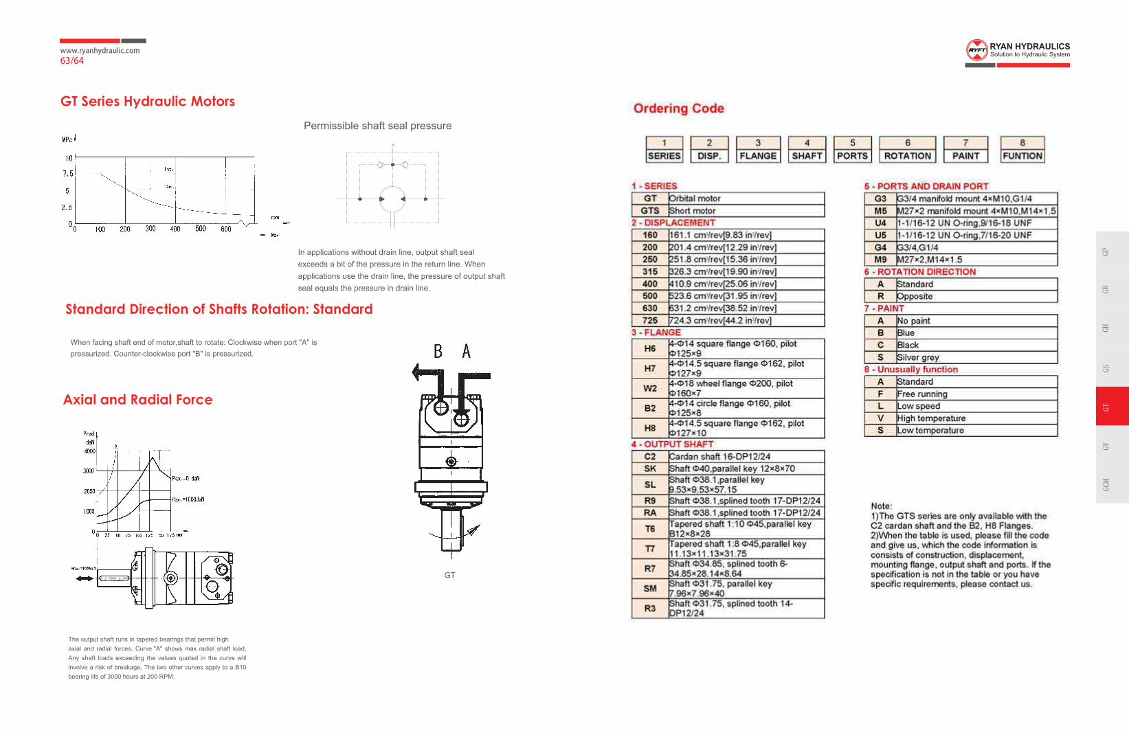
www.ryanhydraulic.com63/64
GT Series Hydraulic Motors
Standard Direction of Shafts Rotation: Standard
Axial and Radial Force
In applications without drain line, output shaft seal exceeds a bit of the pressure in the return line. When applications use the drain line, the pressure of output shaft seal equals the pressure in drain line.
The output shaft runs in tapered bearings that permit high axial and radial forces, Curve "A" shows max radial shaft load, Any shaft loads exceeding the values quoted in the curve will involve a risk of breakage, The two other curves apply to a B10 bearing life of 3000 hours at 200 RPM.
When facing shaft end of motor,shaft to rotate: Clockwise when port "A" is pressurized. Counter-clockwise port "B" is pressurized.
GPGR
GHGS
GTGV
GGM
Permissible shaft seal pressure
GT

Pressure Loss
Q, GPM
Q, lpm
0 20 40 60 80 100 120 140 160 180 200
0 5 10 15 20 25 30 35 40 45 50 550
50
100
150
200
250
02468
10121416
140 [2030 ]
][ 5403012
Pressure drop[ ]bar PSI
Viscosit y[ ]mm /s SU S2
Oi l flow indrai n line
[ ]lpm GP M20 [98 ]
35 [164 ]20 [98 ]
35 [164 ]
3 [.793 ].52 8
1.58 5[1.057 ]
2 [ ]6 [ ]4
Oil Flow in Drain Line
Max. Displacement,Max. Speed,Max. TorqueMax. Output,Max. Pressure Drop,Max. Oil Flo w,Min. Speed,Permissible Shaft LoadsPressure flui d
Temperature range,
Optimal Viscosity range,Filtration
cm /rev [in /rev][RPM]
daNm [lb-in]kW [HP]bar [PSI]
lpm [GPM][RPM]
daN [lbs]
C [ F]
mm /s [SUS]
3 3
O O
2
801,8 48.91
188 1665064 85,8
200 2900
1500 3300
20÷75 98÷347
[ ]630
cont.: [ ] int.: 211 [18650][ ]
cont.: [ ] int.: 240 [3480]240 [63.4]
5P = [ ]
Mineral based- HLP(DIN 51524) or HM(ISO 6743/4)
[ ]
ISO code 20/16 (Min. recommended fluid filtration of 25 microns)
a
-40÷140 [-40÷284]
General
Type GV315
314 5
19.18
92 8150
111 9800
129 11400
42,5 57
51 68.4
200 2900
240 3 0
280 4 0
160 42
200 5
210 30 0
250 36 0
300 4 0
140 20 0
175 25 0
210 30
71 6300
85 7500
31,8 70.1
22,7 50
,
[ ]
510
630
[ ]
[ ]
[ ]
[ ]
[ ]
[ ]
[ 48 ]
[ 06 ]
[ .3]
[ 2.8]
[ 5 ]
[ 2 ]
[ 35 ]
[ 4 ]
[ 4 ]
[ 50]
8 [120]
[ ]
[ ]
10
[ ]
[ ]
400,9
24.45
118 10450
141 12500
164 14500
53,5 71.7
64 85.8
200 [2900]
240 [3480]
280 [4060]
200 5
240 63
210 [3050]
250 [3620]
300 [4350]
140 [2040]
175 [2540]
210 [3050]
8 [120]
91 8100
109 9600
32,6 71.9
23,5 51.8
[ ]
500
600
[ ]
[ ]
[ ]
[ ]
[ ]
[ 2.8]
[ .4]
[ ]
[ ]
9
[ ]
[ ]
499,6
30.48
146 12950
176 15550
205 18150
53,5 71.7
64 85.8
200 [2900]
240 [3480]
280 [4060]
200 [52.8]
240 [63.4]
210 [3050]
250 [3620]
300 [4350]
140 [2040]
175 [2540]
210 [3050]
8 [120]
113 10000
136 12000
33,5 73.8
24,4 53.8
[ ]
400
480
[ ]
[ ]
[ ]
[ ]
[ ]
[ ]
[ ]
8
[ ]
[ ]
629,1
38.38
166 14700
194 17150
221 19550
48 64.4
56 75
180 26 0
210 3050
240 3 0
200 [52.8]
240 [63.4
210 [3050]
250 [3620]
300 [4350]
140 [2040]
175 [2540]
210 [3050]
8 [120]
133 11800
155 13700
34,9 76.9
25,6 56.4
[ ]
320
380
[ ]
[ ]
[ ]
[ ]
[ ]
[ 1 ]
[ ]
[ 48 ]
[ ]
[ ]
6
[ ]
[ ]
801,8
48.91
188 16650
211 18650
247 21850
42,5 57
48 64.4
160 23 0
180 26 0
210 3050
200 [52.8]
240 [63.4
210 [3050]
250 [3620]
300 [4350]
140 [2040]
175 [2540]
210 [3050]
8 [120]
151 13400
170 15000
36,5 80.527,7 61.1
[ ]
250
300
[ ]
[ ]
[ ]
[ ]
[ ]
[ 2 ]
[ 1 ]
[ ]
]
[ ]
[ ]
5
[ ][ ]
GV400
GV500
GV630
GV800
Displacement,
[ ]
Max. Speed,
[RPM]
Max. Torque
Max. Output
[ ]
Max.Pressure Drop
Max. Oil Flow
Max. Inlet Pressure
Max. Return Pressure
wit h Drai n Lin e
Max. Startin g Pressure with
Unloaded Shaft,bar[PSI]
Min. Starting Torque
Min. Speed***, [RPM]
Weight,kg[lb]
cm /rev In /rev
daNm[lb-in]
kW HP
bav [PSI]
lp m [GPM]
bar [PSI]
bar [PSI]
daNm [lb-in]
3 3
Cont.
Int.*
Cont.
Int.*
Peak**
Cont.
Int.*
Cont.
Int.*
Peak**
Cont.
Int.*
Cont.
Int.*
Peak**
Cont.
Int.*
Peak**
At max. press. drop Cont.
At max. press. drop Int.*
Specifications
ConveyorsMetal working machinesRoad building machinesMining machineryFood industries Agricultural machines Special vehiclesPlastic and rubber machinery etc.
●●●●●●●
OptionsModel - Disc valve, roll-gerotorFlange mountShort motorSide portsShafts - straight, splined and taperedBSPP portsOther special features
●●●●●●●
***
***
●●●
●●●
Intermittent operation: the permissible values may occur for max. 10% of every minute. Peak load: the permissible values may occur for max. 1% of every minute.For speeds lower than given, consult factory or your regional manager.
1. Intermittent speed and intermittent pressure must not occur simultaneously.2. Recommended filtration is per ISO cleanliness code 20/16. A nominal f ltration of 25 micron or better.3. Recommend using a premium quality, anti-wear type mineral based hydraulic oil HLP(DIN51524) orHM ( ISO 6743/4).
If using synthetic fluids consult the factory for alternative seal materials.4. Recommended minimum oil viscosity 13 mm²/s [70 SUS] at 50°C [122°F].5. Recommended maximum system operating temperature is 82°C [180°F].6. To assure optimum motor life fill with fluid prior to loading and run at moderate load and speed for 10-15 minutes.
www.ryanhydraulic.com
65/66
GV Series Orbital Motors
Application
GV
GVS
GPGR
GHGS
GTGV
GGM
●

www.ryanhydraulic.com67/68
MdaNm
0
0510 052 00205 055 005 054 004 053 003001 min (rpm)-1
n
20
40
60
80 cont
.
cont.
int.
int.
100
120
140
160
600
Q=1
0 l/m
in
0
0510 052 00205 056055 005 054 004 053 003001
p=240 bar
200 bar
175 bar
140 bar
105 bar
70 bar
35 bar
min (rpm)-1
n
20
40
60
80
cont
.
cont.
int.
int.
100
120
600
25 l/
min
30 kW
40 kW 50 kW
N=5 kW
10 kW
20 kW
80%
70%
85%
GV 315 GV 400
Function Diagrams
N=5 kW 10 kW
20 kW
30 kW
40 kW
50 kW
85%
80%
70%
87%
2.6
GPM
6.6
GPM
50 l/
min
13.2
GPM
75 l/
min
19.8
GPM
100
l/min
26.4
GPM
125
l/min
33 G
PM
150
l/min
39.6
GPM
160
l/min
42.3
GPM
200
l/min
52.8
GPM
3480 PSI
2900 PSI
2540 PSI
2030 PSI
1520 PSI
1020 PSI
510 PSI0
1000
2000
3000
4000
5000
6000
7000
8000
9000
10000
11000
Mlb-in
MdaNm
25 l/
min
2.6
GPM
6.6
GPM
50 l/
min
13.2
GPM
75 l/
min
19.8
GPM
100
l/min
26.4
GPM
125
l/min
33 G
PM
150
l/min
39.6
GPM
175
l/min
46.2
GPM
200
l/min
52.8
GPM
Q=1
0 l/m
in
240
l/min
63.4
GPM
p=240 bar
200 bar
175 bar
140 bar
105 bar
70 bar
35 bar
3480 PSI
2900 PSI
2540 PSI
2030 PSI
1520 PSI
1020 PSI
510 PSI0
Mlb-in
1000
2000
3000
4000
5000
6000
7000
8000
9000
10000
11000
12000
13000
14000
15000
MdaNm
0
0510 052 00205 005 054 004 053 003001 min (rpm)-1
n
20
40
60
80
cont
.
cont.
int.
int.
100
120
140
160
180
GV 500
N=5 kW
10 kW
20 kW
30 kW
40 kW60 kW
85%
80%70%
87%
50 kW
Mlb-in
0100020003000400050006000700080009000
10000110001200013000140001500016000
p=240 bar
200 bar
175 bar
140 bar
105 bar
70 bar
35 bar
3480 PSI
2900 PSI
2540 PSI
2030 PSI
1520 PSI
1020 PSI
510 PSI
Q=1
0 l/m
in2.
6 G
PM25
l/m
in6.
6 G
PM
50 l/
min
13.2
GPM
75 l/
min
19.8
GPM
100
l/min
26.4
GPM
125
l/min
PM33
G
150
l/min
39.6
GPM
175
l/min
46 G
PM
200
l/min
PM52
.8 G
240
l/min
63.4
GPM M
daNm
0
0510 05200205 004053003001 min (rpm)-1
n
25
50
75
cont.
int.
cont
.
int.
100
125
150
175
200
GV 630
N=5 kW
10 kW
20 kW
30 kW40 kW
60 kW
85% 80%70%
87%
50 kW
p=240 bar
180 bar
3480 PSI
2610 PSI
150 bar2175 PSI
120 bar1740 PSI
90 bar1305 PSI
60 bar870 PSI
30 bar435 PSI
Q=1
0 l/m
in2.
6 G
PM25
l/m
in6.
6 G
PM
50 l/
min
13.2
GPM
75 l/
min
19.8
GPM
100
l/min
26.4
GPM
125
l/min
33 G
PM
150
l/min
39.6
GPM
175
l/min
46 G
PM
200
l/min
52.8
GPM
240
l/min
63.4
GPM
0
Mlb-in
100020003000400050006000700080009000
100001100012000130001400015000160001700018000
MdaNm
0
0510 05200205 003001 min (rpm)-1
n
25
50
75
cont.
cont
.in
t.
int.
100
125
150
175
200
225
GV 800
N=5 kW
10 kW
20 kW30 kW
40 kW
80%
70%
85%
Q=1
0 l/m
in2.
6 G
PM25
l/m
in6.
6 G
PM
50 l/
min
13.2
GPM
75 l/
min
19.8
GPM
100
l/min
PM26
.4 G
125
l/min
33 G
PM
150
l/min
39.6
GPM
175
l/min
46 G
PM
200
l/min
52.8
GPM
240
l/min
63.4
GPM
p=180 bar
160 bar2610 PSI
2320 PSI
130 bar1885 PSI
100 bar1450 PSI
75 bar1090 PSI
50 bar720 PSI
25 bar360 PSI
Mlb-in
0100020003000400050006000700080009000
1000011000120001300014000150001600017000180001900020000
Flange W3
Mounting
Content Code
G5 (depth) M6 (depth) U6 (depth) G6 (depth) M7(depth) U7(depth)
P(A,B)
T
C
G1 (18)
G1/4 (12)
4-M12 (10)
M33 x 2 (18)
M14 x 1.5 (12)
4-M12 (10)
1-5/16-12UN(18)
9/16-18UNF(12)
--
1-5/16-12UN(18)
7/16-20UNF(12)
--
G1 (18)
G1/4 (12)
--
M33 x 2 (18)
M14 x 1.5 (12)
--
ModelGV315GV400GV500GV630GV800
L217224232244255
L12027354758
L2161.5168.5176.5188.5199.5
Drain port T
G5、M6 PORT
GV Dimensions and Mounting
Flange H9
GPGR
GHGS
GTGV
GGM
The function diagrams data is for average performance ofrandomly selected motors at back pressure5÷10 bar [72.5÷145 PSI] and oil with viscosityof 32mm²/s[150 SUS] at 50°C[122°F]
U6、G6、M7、U7 PORT
Note:1)
2)
The width of the roll-gerotor is 4 mm greater than L1. If the mounting W3 is used, the dimensions of L and L2 should minus 68 mm.
Drain port T
C

GPGR
GHGS
GTGV
GGM
www.ryanhydraulic.com
69/70
Dimensions and Mounting
B3
Dimensions of the Attached Components
Drain ConnectionGVSGVS
GVSGVSGVS

www.ryanhydraulic.com71/72
GPGR
GHGS
GTGV
GGM
GV Shaft Extensions Dimensions
Shaft SN: Cylindrical shaft
ø50 Parallel key 14x9x70
Shaft RB: Splined key 16-DP8/16Max. Torque 271.2 daNm[24000 lb-in] Shaft RC: Splined key 16-DP8/16
Max. Torque 271.2 daNm[24000 lb-in]
3/8-16UNC depth 20
Shaft SP: Cylindrical shaft
ø 57.15 Parallel key 12.7x12.7x57 Max. Torque 271.2 daNm[24000 lb-in]
M12 depth 25
M12 depth 253/8-16UNC depth 20
Shaft T8: Tapered shaft ø60 Parallel key16x10x32Tightening torque: 75±50NmMax. Torque 271.2 daNm[24000 lb-in]
Shaft T9: Tapered shaft ø57.2 Parallel key 14.308x14.308x50Tightening torque: 750±50NmMax. Torque 271.2 daNm[24000 lb-in]
Permissible shaft seal pressure
Standard direction of shaft rotation: Standard
In applications without drain line, output shaft seal exceeds a bit of the pressure in the return line. When applications use the drain line, the pressure of output shaft seal equals the pressure in drain line.
Axial and Radial forces
The output shaft runs in tapered bearings that permit high axial and radial forces, Curve "A" shows max radial shaft load, Any shaft loads exceeding ehtvalues quoted in the curve will involve a risk of breakage, The two sevruc rehtoapply to a B10 bearing life of 3000 hours at 200 RPM.
When facing shaft end of motor, shaft to rotate: Clockwise when port "A" is pressurized. Counter-clockwise port "B" is pressurized.
Max. Torque 210.7 daNm[18650 lb-in]

www.ryanhydraulic.com73/74
Specifications for GGM SeriesDescription ..................................................Hydraulic Motors
Flow Range..........................................To 15 GPM (56.7 LTR)
Displacements..................... To.700 C.I.R.(11.47 CC’s/REV.)
Maximum Pressure to ............................2000 PSI (137 BAR)
Maximum Speed to .................................................5000 RPM
Rotation .............................................................. Bi-Directional
Bearings ...........................................................................Roller
Construction .............................................................Aluminum
GGM Specifications
Performance Displacement/Revolution Maximum Continuous Maximum
(Theoretical) Pressure SpeedMotor
Inches Liters Centimenters Gallons PSI BAR RPMCubic Cubic Imperial
GGM3.6 .0010 .218 .0039 3.572 .0008 2000 138 5000GGM6.1 .0016 .372 .0062 6.096 .0013 2000 138 5000GGM7.4 .0020 .450 .0078 7.374 .0016 2000 138 5000GGM9.5 .0025 .580 .0097 9.505 .0021 2000 138 5000GGM11.5 .0030 .700 .0116 11.471 .0025 1500 104 5000
MODEL NO. GGM3.6 GGM6.1 GGM7.4 GGM9.5 GGM11.5DISPLACEMENT .218 in.3 .372 in.3 .450 in.3 .580 in.3 .700 in.3
PER REVOLUTION (3.57 cm3) (6.094 cm3) (7.374 cm3) (9.50 cm3) (11.471 cm3)MAXIMUM 5000 5000 5000 5000 5000RATED RPMRATED FLOW PER .95 GPM 1.61 GPM 1.95 GPM 2.51 GPM 3.03 GPM1000 RPM (NOMINAL) (3.6 liters/min) (6.1 liters/min) (7.4 liters/min) (9.5 liters/min) (11.5 liters/min)MAXIMUM CONTINUOUS 2000 PSI 2000 PSI 2000 PSI 2000 PSI 1500 PSI
RATED(138.0 bar) (138.0 bar) (138.0 bar) (138.0 bar) (103.5 bar)
PRESSURE INTERMITTENT 2500 PSI 2500 PSI 2500 PSI 2500 PSI 2000 PSI
(172.5 bar) (172.5 bar) (172.5 bar) (172.5 bar) (138.0 bar)OUTPUT TORQUE PER 1000 PSI* 35 in.-lbs. 59 in.-lbs. 72 in.-lbs. 92 in.-lbs. 111 in.-lbs. (69.0 bar) (40 kg-cm) (68 kg-cm) (83 kg-cm) (107 kg-cm) (128 kg-cm)WEIGHT 2.8 pounds 3.0 pounds 3.1 pounds 3.3 pounds 3.5 pounds
(1.25 kg) (1.36 kg) (1.41 kg) (1.50 kg) (1.59 kg)SHAFT SIDE LOAD** 170 lbs. 130 lbs. 110 lbs. 70 lbs. 30 lbs.
(77.0 kg) (59.0 kg) (50.0 kg) (31.7 kg) (13.5 kg)
* THEORETICAL** SIDE LOAD: Maximum Permissible Shaft Side Load
at 2500 RPM and 1000 PSI (69.0 bar) (B-10 Bearing Life of 1000 Hrs.)
180° F (82.2° C)
OIL VISCOSITY: Recommended viscosity 150 SUS (3.65 engler).(32 centistokes) Minimum recommended viscosity60 SUS (2.1 engler) (13 centistokes)
FILTRATION: Minimum recommended filtration 10 Micron.END THRUST: 80 LBS. (36.3 kg.) maximum.
WARNINGNever exceed the INTERMITTENT
pressure rating or 5000 RPM
When used in series circuits, back pressure is not to exceed 1000 (69.0 BAR) PSI.
GGM Displacement
Model
GPGR
GHGS
GTGV
GGM
USGallons
OIL TEMPERATURE:Maximum recommended oil temperature

www.ryanhydraulic.com
75/76
GGM Dimensions
Mounting Dimensions
MODEL NO.
‘P’STRAIGHT TH’D
O-RING PORT PERSAE SPEC. 514d
GGM3.6 SAE 8(3/4-16UNF)GGM6.1 SAE 8(3/4-16UNF)GGM7.4 SAE 8(3/4-16UNF)GGM9.5 SAE 10(7/8-14UNF)GGM11.5 SAE 10(7/8-14UNF)
FLANGE ‘W’2-BOLT ‘A-A’ 6.3 (.25)
4-BOLT 6.3 (.25)2-BOLT ‘A’ 9.5 (.38)
Cover Plate Available
52.4
( )
2.8(.11)
90.0(3.54)
45.0(1.77)
'P'2-Places
CLCCDriveShaft
A Rear Porting
28.4 Min.(1.12) Full Keyway
38.1(1.50)
3.25(.128)
14.3(.562) Dia.12.6 (.498)
12.4 (.488)
Design, Shafts and Mounting Flange
Design Available
A BGGM - Bi-DirectionalStandard Seal
GGM - Bi-DirectionalWith Dust Seal
Shafts Available
SQ
SR
9/16 Dia. Keyed ShaftTorque Limit 39 Lbs. Ft. (52.9 Nm)
9/16 Dia. 8 Tooth Spline ShaftFlat Root Side Fit-Class 2 FitTorque Limit 39 Lbs. Ft. (52.9 Nm)
5/8 Dia. 9 Tooth Spline ShaftFlat Root Side Fit - Class 1 FitTorque Limit 52 Lbs. Ft. (70.5 Nm) Available as Standard in Models
7/16 Dia. Keyed ShaftTorque Limit 19 Lbs. Ft. (25.8 Nm) Available as Standard in Models
9/16 Dia. 8 Tooth Spline ShaftFlat-Root Side Fit-Class 2 FitTorque Limit 39 Lbs. Ft. (52.9 Nm) Available as Standard in Models
22.1(.87)
Min. FullSpline
31.7(1.25)
28.4(1.12)
3/32 x 1/2Woodruff Key Slot
11.14 (.4375)11.10 (.4370) Dia.
Spline DataPitch Diameter .... 16/32Pressure Angle ....... 30°No. of Teeth ................ 8
Spline DataPitch Diameter .... 16/32Pressure Angle ....... 30°No. of Teeth ................ 9
10.3(.406)
Min. FullSpline
19.0(.75)
Spline DataPitch Diameter .... 16/32Pressure Angle ....... 30°No. of Teeth ................ 8
28.4(1.12)
Min. FullSpline
38.1(1.50)
RD RF
RG
GPGR
GHGS
GTGV
GGM
RotationWhen facing shaft end of motor,shaft to rotate: Counter-clockwise port"A" is pressurized.

www.ryanhydraulic.com77/78
106.4(4.19)
53.2(2.09)
82.5(3.25)Dia.Pilot
5.6(.22)
R
47.7R.(1.88)
82.5(3.25)
41.3(1.62)
63.5 Dia.(2.50)
9.6 R(.38)
10.4(.41)
50.8(2.00)DIA.PILOT
7.1(.28)
50.8(2.00)
25.4(1.00) 45.2 Dia. Pilot
(1.78)4.8 R
(.19)
69.8 Sq.(2.75)
25.4(1.00)
50.8(2.00)
Mounting Flange Available
SAE ‘AA’ 2-Bolt 4-Bolt SAE ‘A’ 2-BoltHB HA HC
GGM Torque and Speed Selection Charts
GGM3.6 Motor250
200
150
100
50
0
18
16
14
12
10
8
6
4
2
0
250
200
150
100
50
0
65
60
55
50
45
35
40
30
25
20
15
10
5
0
Out
put To
rque
- In
.- Lb
s.O
utpu
t Pow
er-H
P (U
S)
18
16
14
12
10
8
6
4
2
0
Inpu
t Flo
w G
PM
Out
put To
rque
-Kg-
cmIn
put F
low
-lite
rs/m
in.
1000 2000 3000 4000 5000
RPM
2000 PSI (138,0 bar)1500 PSI (103,5 bar)1000 PSI (69,0 bar)500 PSI (34,5 bar)
2000 PSI (138,0 bar)1500 PSI (103,5 bar)1000 PSI (69,0 bar)500 PSI (34,5 bar)
2000 PSI (138,0 bar)1500 PSI (103,5 bar)1000 PSI (69,0 bar)500 PSI (34,5 bar)
GGM6.1250
200
150
100
50
0
18
16
14
12
10
8
6
4
2
0
250
200
150
100
50
0
65
60
55
50
45
35
40
30
25
20
15
10
5
0
Out
put To
rque
- In
.- Lb
s.O
utpu
t Pow
er-H
P (U
S)
18
16
14
12
10
8
6
4
2
0
Inpu
t Flo
w G
PM
Out
put To
rque
-Kg-
cmIn
put F
low
-lite
rs/m
in.
1000 2000 3000 4000 5000
RPM
2000 PSI (138,0 bar)1500 PSI (103,5 bar)1000 PSI (69,0 bar)500 PSI (34,5 bar)
2000 PSI (138,0 bar)1500 PSI (103,5 bar)1000 PSI (69,0 bar)500 PSI (34,5 bar)
2000 PSI (138,0 bar)
1500 PSI (103,5 bar)
1000 PSI (69,0 bar)
500 PSI (34,5 bar)
GGM11.5 Motor250
200
150
100
50
0
18
16
14
12
10
8
6
4
2
0
250
200
150
100
50
0
65
60
55
50
45
35
40
30
25
20
15
10
5
0
Out
put To
rque
- In
.- Lb
s.O
utpu
t Pow
er-H
P (U
S)
18
16
14
12
10
8
6
4
2
0
Inpu
t Flo
w G
PM
Out
put To
rque
-Kg-
cmIn
put F
low
-lite
rs/m
in.
1000 2000 3000 4000 5000
RPM
2000 P
SI (138,0 b
ar)
1500 PSI (103,5 bar)
1000 PSI (69,0 bar)
500 PSI (34,5 bar)
2000 PSI (138,0 bar)
1500 PSI (103,5 bar)
1000 PSI (69,0 bar)
500 PSI (34,5 bar)
2000 PSI (138,0 bar)1500 PSI (103,5 bar)1000 PSI (69,0 bar)500 PSI (34,5 bar)
250
200
15
100
5
0 500 1000 1500 2000 2500
Differential Pressure (PSI)
Star
ting
Tor
que
(Inch
-Pou
nds)
GGM
11.5
Motor Starting Torque
GGM7.4 Motor250
200
150
100
50
0
18
16
14
12
10
8
6
4
2
0
250
200
150
100
50
0
65
60
55
50
45
35
40
30
25
20
15
10
5
0
Out
put To
rque
- In
.- Lb
s.O
utpu
t Pow
er-H
P (U
S)
18
16
14
12
10
8
6
4
2
0
Inpu
t Flo
w G
PM
Out
put To
rque
-Kg-
cmIn
put F
low
-lite
rs/m
in.
1000 2000 3000 4000 5000
RPM
2000 PSI (138,0 bar)1500 PSI (103,5 bar)1000 PSI (69,0 bar)500 PSI (34,5 bar)
2000 PSI (138,0 bar)
1500 PSI (103,5 bar)
1000 PSI (69,0 bar)
500 PSI (34,5 bar)
2000 PSI (138,0 bar)1500 PSI (103,5 bar)1000 PSI (69,0 bar)500 PSI (34,5 bar)
GGM9.5250
200
150
100
50
0
18
16
14
12
10
8
6
4
2
0
250
200
150
100
50
0
65
60
55
50
45
35
40
30
25
20
15
10
5
0
Out
put To
rque
- In
.- Lb
s.O
utpu
t Pow
er-H
P (U
S)
18
16
14
12
10
8
6
4
2
0
Inpu
t Flo
w G
PM
Out
put To
rque
-Kg-
cmIn
put F
low
-lite
rs/m
in.
1000 2000 3000 4000 5000
RPM
2000 PSI (138,0 bar)1500 PSI (103,5 bar)1000 PSI (69,0 bar)500 PSI (34,5 bar)
2000 PSI (138,0 bar)
1500 PSI (103,5 bar)
1000 PSI (69,0 bar)
500 PSI (34,5 bar)
2000 PSI (138,0 bar)
1500 PSI (103,5 bar)
1000 PSI (69,0 bar)
500 PSI (34,5 bar)
GGM Torque and Speed Selection Charts
GGM9.5
GGM7.4
GGM6.1
GGM3.6
GPGR
GHGS
GTGV
GGM

www.ryanhydraulic.com79