orderrite™ - everbrite tech...
TRANSCRIPT

IN449602S Rev.E 1 10/13/2016
OrderRite™
6.x LCD Order Confirmation System
Monolith Instruction Manual for OCS Editor

IN449602S Rev.E 2 10/13/2016
Table of Contents
Table of Contents ................................................................................................................................................ 2 Installation Instructions ........................................................................................................................................ 4
General Requirements .................................................................................................................................... 4 Unpacking the Hardware ................................................................................................................................. 4 Sign Installation Procedure ............................................................................................................................. 4 Store Installation Procedure ............................................................................................................................ 8 Completing the Install .................................................................................................................................... 10
System Testing .................................................................................................................................................. 11 Partial Loopback Test .................................................................................................................................... 11 Full Loopback Test – POS Port ..................................................................................................................... 12 Full Loopback Test – PC Port ....................................................................................................................... 13
Software Installation and Operation .................................................................................................................. 14 Initial Software Configuration ........................................................................................................................ 14 Setting the OCS Date and Time .................................................................................................................... 16 OCS Editor Operational Details .................................................................................................................... 16 OCS Update Utility Operational Details ........................................................................................................ 19
Troubleshooting ................................................................................................................................................. 22 Hardware Problems ....................................................................................................................................... 22 Software Problems ........................................................................................................................................ 25
Service and Maintenance .................................................................................................................................. 27 Replacing the Compact Flash ....................................................................................................................... 27 Removing the Electronics.............................................................................................................................. 29 Reinstalling the Electronics ........................................................................................................................... 29 Cleaning the Outdoor OCS Cabinet .............................................................................................................. 30
System Operation .............................................................................................................................................. 31 OCS Sign Operation Overview ..................................................................................................................... 31 Converter Box Operation............................................................................................................................... 31
Appendices ........................................................................................................................................................ 33 Appendix A: OCS Install and Dimensional Drawing ..................................................................................... 33 Appendix B: Ethernet Connector Crimping Instructions ................................................................................ 34 Appendix C: Specifications............................................................................................................................ 35 Appendix D: Warranty ................................................................................................................................... 36

IN449602S Rev.E 3 10/13/2016
Legal notices Copyright © 2016 Everbrite, LLC. All rights reserved. Everbrite and OrderRite logos are trademarks or registered trademarks of Everbrite, LLC. Reproduction, transfer, distribution, or storage of part or all of the contents in this document in any form without the prior written permission of Everbrite is prohibited. Everbrite operates a policy of on-going development. Everbrite reserves the right to make changes and improvements to any of the products described in this document without prior notice. Under no circumstances shall Everbrite be responsible for any loss of data or data or income or any special, incidental, consequential, or indirect damages howsoever caused. THE CONTENTS OF THIS DOCUMENT ARE PROVIDED “AS IS.” EXCEPT AS REQUIRED BY APPLICABLE LAW, NO WARRANTIES OF ANY KIND, EITHER EXPRESS OR IMPLIED, INCLUDING, BUT NOT LIMITED TO, THE IMPLIED WARRANTIES OF MERCHANTABILITY AND FITNESS FOR A PARTICULAR PURPOSE, ARE MADE IN RELATION TO THE ACCURACY, RELIABILITY OR CONTENTS OF THIS DOCUMENT. EVERBRITE RESERVES THE RIGHT TO REVISE THIS DOCUMENT OR WITHDRAW IT AT ANY TIME WITHOUT PRIOR NOTICE. Trademarks Product names and/or brands mentioned herein are trademarks or registered trademarks of their respective holders. Export Controls This product contains commodities, technology or software exported from the United States in accordance with the Export Administration regulations. Diversion contrary to U.S. law is prohibited.

IN449602S Rev.E 4 10/13/2016
Installation Instructions
General Requirements
Speaker and microphone are supplied by either an audio vendor or from existing system
Installer needs to ensure the sign is properly installed, connected, and grounded per all local codes
Concrete sign foundation with cable conduits of proper number and size need to be present (see Appendix A: OCS Install and Dimensional Drawing for details)
Connected primaries must remain in the conduit and be properly sealed to conduit at the foundation
Everbrite UL file is #E6733
Unpacking the Hardware
Carefully unpack the Order Confirmation System (OCS) and examine it for any shipping damage. Remove the back of the OCS by unscrewing the rear Torx T15/Phillips mounting screws and set panel/screws aside on a clean, dry surface. Remove the POS kit container. Note: The POS kit contains important items required for the installation – keep all these items together until used. This manual assumes that the store will use both a serial (data cable, converter box, etc.) and network (Ethernet cable) connection – only one of these two connections is mandatory. The contents of the POS kit will reflect the customer’s requirements so ignore the serial or network content if these pieces of hardware are missing. If you believe hardware is missing that should be present, contact Everbrite.
Sign Installation Procedure
1. Remove the existing speaker stand from the foundation (if applicable).
2. Obtain the RS-485 data cable spool (yellow with DB-9 connector) and the CAT-5e Ethernet cable spool (white) from the POS kit located in the OCS (see Unpacking the Hardware above).
3. Pull both cables through the 1.5" data conduit from inside the store to the concrete foundation. The data cable end with the attached DB-9 connector is to be located inside the store and must be within 10 feet of the POS connection (register or backoffice PC). The Ethernet cable should be run into a network switch or router; if this connection won't be used, coil a generous portion of the cable in a location where it can be found later. Leave at least 4 feet of extra cable at the sign foundation and coil a generous portion of the cable inside the equipment rack or in the ceiling above. If extra cable length will be stored in the ceiling, ensure that it is secured to the structure to prevent future injury.
Do not pull the data cable or Ethernet cable through the primary power conduit or the operation of the system will be compromised.
4. Attach the OCS to the concrete foundation making sure it is level.
5. Remove the speaker and microphone from the existing speaker stand (if applicable). Separate the speaker from the microphone if contained as a single unit. Make sure to label the wires in order to ensure properly reconnection later.
6. Remove the block of foam insulation packing within the microphone area above the LCD housing. Leave the foam wind screen and circular gasket attached to the microphone grill (if present).

IN449602S Rev.E 5 10/13/2016
7. Using a utility knife, cut a hole in the center of the block of foam large enough to insert microphone (DO NOT cut hole all the way through foam. The back of the microphone must be covered with foam). The microphone should fit snuggly within foam, and must not touch any metal when positioned in the cabinet. IMPORTANT! If microphone touches the metal of the cabinet, sound quality will be greatly reduced. Create a hole inside of the foam for the cable to exit (see figure below).
8. Guide the microphone cable down through the right side channel (looking from back of cabinet) for connection. The cable cannot interfere with the operation of servicing the electronics.
MICROPHONE INSTALLTION DETAIL
9. Remove the sheet metal back which is attached to the speaker support box located just above the external fan shelf.
10. Insert the speaker into the support box. Fill the support box with foam as shown and replace the sheet metal strap (see detail below).

IN449602S Rev.E 6 10/13/2016
SPEAKER INSTALLATION DETAIL
11. Run the speaker cable through the bushing located in the center of the fan shelf. Make the microphone and speaker connections below the shelf. The connections must be soldered. IMPORTANT! Ensure that no cables are impeding the fans from functioning.
12. If the Ethernet cable is to be used, remove (2) RJ-45 connectors from the POS kit and crimp them
onto each end of the white CAT-5e Ethernet cable (see detail below). For more information, see Appendix B: Ethernet Connector Crimping Instructions.
RJ-45 ETHERNET CRIMP CONNECTION DETAIL
13. Locate the yellow data cable pigtail coming out of the LCD electronics housing and connect it to the data cable coming from the conduit using the supplied gel crimp connectors (see detail below). Make sure the quick disconnect remains between the LCD electronics housing and the splice point.

IN449602S Rev.E 7 10/13/2016
RS-485 DATA CABLE CONNECTION DETAIL
14. Locate the white Ethernet cable coming from the conduit and plug it into the open jack of the surge suppressor located just below the external fans (see detail below).
CAT-5e ETHERNET CABLE CONNECTION DETAIL
IMPORTANT! THIS SIGN MUST BE WIRED TO A DEDICATED ELECTRICAL CIRCUIT BREAKER. Before making primary connections, make sure the power is off.
15. Feed the primary power wires from the power conduit into power switch box and terminate the connections (black to black, white to white, green to green).

IN449602S Rev.E 8 10/13/2016
Store Installation Procedure
16. Remove the red auto-switching converter box from the POS kit and mount it to a clean and dry vertical surface within 10 feet of the POS system connection point (register or back office PC). Make sure the location does not interfere with day to day operations. Avoid mounting the converter in wet locations likely to be exposed to significant moisture. Make sure the converter is mounted such that the yellow data cable can reach the OCS port.
Fill in the OCS#____ on the label identifying the number of the OCS which the converter box is controlling (OCS 1 or 2) with a permanent marker.
AUTO-SWITCHING CONVERTER BOX DETAIL
17. IMPORTANT! If the POS cable terminates in any other connector but a DB-9, a test adapter will be included in the POS kit. Mount it in the “Full Test Output” port for later testing.
18. Apply the appropriate label from the label sheet in the POS kit to the jacket of the yellow data cable and plug cable into converter (see detail below). Make sure to use the label with correct OCS number (1 or 2).
19. Locate the 10 foot (POS) serial cable from the POS kit and identify the POS register and COM port that will be sending data to the OCS.
20. Apply cable labels, run the cable and terminate both ends of the POS serial cable (see detail below). Make sure to use the label with correct OCS number (1 or 2), POS register number and the COM port number. Extra labels are provided for special cases.

IN449602S Rev.E 9 10/13/2016
21. For serial updates via USB port: Locate the USB cable from the POS kit. This cable typically plugs into a PC which can run the Everbrite software for image changing, program updates and other diagnostics. If this cable is not installed, orders will still appear on the OCS.
Apply the cable label and insert the converter-end of the cable into the converter box. To secure the cable, an included self-adhesive anchor pad and zip tie can be used (see details below). Make sure to use the label with correct OCS number (1 or 2). Tip: Coil the USB cable around the converter for laptop access.
22. For serial updates via serial port: Locate the 100 foot (PC Update) serial cable from the POS kit and discuss with the store manager where to run the cable. This cable typically plugs into a PC which can run the Everbrite software for image changing, program updates and other diagnostics. If this cable is not installed, orders will still appear on the OCS.
Apply cable labels, run the cable and terminate both ends of the PC Update serial cable (see detail below). Make sure to use the label with correct OCS number (1 or 2). Note: This connection is not necessary if using the USB port in previous step.
23. For reliable operation, make sure all cable ends are screwed in and tightened.
24. Locate the white Ethernet cable (optional) that was run through the conduit from the OCS and apply the appropriate label (see detail below). Make sure to use the label with correct OCS number (1 or 2).
25. Plug the white Ethernet cable into the store's switch or router noted below.
26. Locate the black power adapter wall plug in the POS kit and plug it into a standard power outlet near the converter box. Plug the barrel connector into the "DC In" port on the converter box.

IN449602S Rev.E 10 10/13/2016
Completing the Install
The following steps will verify that the system is working correctly. If any of the following steps fail, see the Troubleshooting section of this manual. If further help is required, contact Everbrite Product Support at (888)877-3092.
27. Apply power to the OCS by flipping on the appropriate circuit breaker and by turning on the rear cabinet power switch. Upon power up, the following application "launch" screen will display:
28. Make sure that the Software Configuration > POS Type matches the POS system used and that all
"Controller Feedback" tests pass (green).
29. Perform POS and PC port loopback tests as described in the System Testing section.
30. At this point, the OCS is in perfect working condition and ready to display orders.
31. Working with store personnel, simulate a drive-thru order and verify that the order is showing up properly on the OCS display. Also verify that the store's slide images are displaying on the OCS between orders.
32. The required installation procedures are now complete and the OCS back panel can now be screwed back in place.
Proceed to the Software Installation and Operation section for details on installing and using the back office software.
IMPORTANT! GIVE THESE INSTRUCTIONS TO THE STORE MANAGER FOR SAFEKEEPING – THEY WILL NEED
THIS MANUAL FOR FUTURE TROUBLESHOOTING AND SOFTWARE INSTALLATION.

IN449602S Rev.E 11 10/13/2016
System Testing
Partial Loopback Test
The loopback test is performed from the red Everbrite converter box which should be mounted near a POS terminal or in the store's back office. The Partial test specifically tests the converter box, data cable and OCS to make sure all devices are interconnected and functioning. Unlike the Full test, it does not require or test any serial cables (ie: POS or PC).
1. Push and hold the white "Partial Test" button on the converter. The amber test LED next to the button will light indicating we’re in test mode. The green "Tx" LED and the red "Rx" LED will flash quickly indicating data back and forth from the OCS.
2. Optionally, release the button within 3 seconds in order to view the test message on the OCS. The
amber test LED will remain on and the test message “99 TEST ITEM 99.99” will stay on the OCS display.
3. If previously released, push and hold the white "Partial Test" button again.
4. The test will end within 7 seconds with either the test “Pass” LED blinking or the test “Fail” LED blinking.
The test message is erased from the OCS and the test is complete. If the test failed, see the Troubleshooting section.

IN449602S Rev.E 12 10/13/2016
Full Loopback Test – POS Port
The loopback test is performed from the red Everbrite converter box which should be mounted near a POS terminal or in the store's back office. The Full test on the POS port specifically tests the POS serial cable, converter box, data cable and OCS to make sure all devices are interconnected and functioning.
1. Trace the serial cable plugged into the converter’s "From POS" port back to the port it is connected to on the POS system. Note this port for later reinsertion.
2. Unplug the cable from this port and reinsert it into the converter’s “Full Test Output” port. Note: In the case of non-DB9 POS cables, a test adapter was provided and should be inserted in the test port. If the POS serial cable is too short and won’t reach the converter, run a Partial test instead which doesn’t use or test this cable (see above).
3. Push and hold the white "Full Test" button on the converter. The amber test LED next to the button will light indicating we’re in test mode. The green "Tx" LED and the red "Rx" LED will flash quickly indicating data back and forth from the OCS.
4. Optionally, release the button within 3 seconds in order to view the test message on the OCS. The amber test LED will remain on and the test message “99 TEST ITEM 99.99” will stay on the OCS display.
5. If previously released, push and hold the white "Full Test" button again.
6. The test will end within 7 seconds with either the test “Pass” LED blinking or the test “Fail” LED blinking.
7. Unplug the serial cable from the “Full Test Output” port (or test adapter) and reconnect it to the POS port noted in the first step.
The test message is erased from the OCS and the test is complete. If the test failed, see the Troubleshooting section.

IN449602S Rev.E 13 10/13/2016
Full Loopback Test – PC Port
The loopback test is performed from the red Everbrite converter box which should be mounted near a POS terminal or in the store's back office. The Full test on the PC port specifically tests the PC serial cable, converter box, data cable and OCS to make sure all devices are interconnected and functioning.
1. Trace the serial cable plugged into the converter’s "From PC" port back to the port it is connected to on the update PC. Note this port for later reinsertion.
2. Unplug the cable from this port and reinsert it into the converter’s “Full Test Output” port. Note: If the PC serial cable is too short and won’t reach the converter, run a Partial test instead which doesn’t use or test this cable (see above).
3. Push and hold the white "Full Test" button on the converter. The amber test LED next to the button will light indicating we’re in test mode. The green "Tx" LED and the red "Rx" LED will flash quickly indicating data back and forth from the OCS.
4. Optionally, release the button within 3 seconds in order to view the test message on the OCS. The
amber test LED will remain on and the test message “99 TEST ITEM 99.99” will stay on the OCS display.
5. If previously released, push and hold the white "Full Test" button again.
6. The test will end within 7 seconds with either the test “Pass” LED blinking or the test “Fail” LED blinking.
7. Unplug the serial cable from the “Full Test Output” port and reconnect it to the PC port noted in the first step.
The test message is erased from the OCS and the test is complete. If the test failed, see the Troubleshooting section.

IN449602S Rev.E 14 10/13/2016
Software Installation and Operation
Note: Whether a computer is available in-store or not, the installer is responsible for setting the current store's Date and Time on the OCS. All certified installers should have a laptop with them onto which the software should be installed. Run the setup/installer from your installation CD or FTP site. Note: Everbrite software can run in a Microsoft Windows "limited" user account, but administrator privileges are required for installation.
Initial Software Configuration
After software installation, the OCS Editor program will start automatically or click Start > Programs > Everbrite OCS Editor Suite > OCS Editor. If the software is not yet configured, a popup window will appear (see figure right) informing the user that the OCS Update Utility needs to run to define connections. This utility will configure how the software will communicate with the OCS. Click OK to load the OCS Update Utility program.
Connection Setup Wizard
Serial or network connections can easily be defined by using the Connection Setup Wizard. The wizard will start automatically if no connections are defined or click the “Connection Setup Wizard” button on the Settings tab.
Defining Serial Connections
Start the Connection Setup Wizard, choose “USB / Serial Connection” and then click “Next”. Use one of the following connection methods:

IN449602S Rev.E 15 10/13/2016
1. Use a USB cable to connect the converter’s "USB" port to the PC’s USB port
2. Use a serial cable to connect the converter’s "From PC" port to the PC’s serial port or USB-serial adapter
Make sure that any the drivers are loaded for any USB devices in use. Click “Next.
Click “Scan for Ports” to scan for available serial ports on the computer. If everything is connected and functioning correctly, an OCS will be detected on a port. Click this port and then click “Next”. To create a connection for this OCS, click “Finish”.
Defining Network Connections
Start the Connection Setup Wizard, choose “Network Connection” and then click “Next”. Click “Scan for OCSs” to scan the local area network for connected OCSs. Click the OCS in the list that is to be modified or selected and then click “Next”. Note: When an OCS is selected, click “Identify OCS” to popup an identifying message on the screen outside. This is useful for identifying two OCSs with similar settings; the units can then be renamed with more descriptive names.
The network settings on the selected OCS can now be modified. Make any changes necessary and then click “Next”. If changes have been made, the wizard will indicate whether the changes were successful.
To create a connection for this OCS, click “Finish”.
IN449602S Rev.E 16 10/13/2016
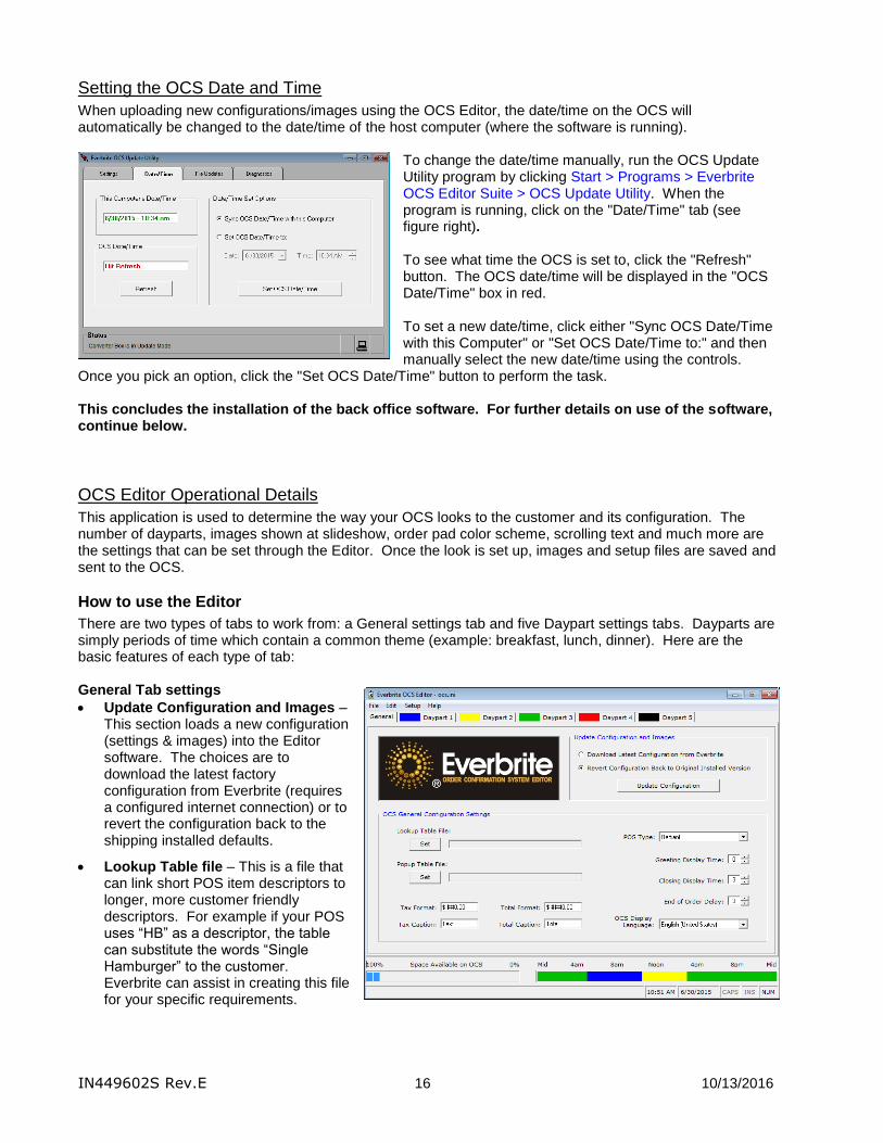
Setting the OCS Date and Time
When uploading new configurations/images using the OCS Editor, the date/time on the OCS will automatically be changed to the date/time of the host computer (where the software is running).
To change the date/time manually, run the OCS Update Utility program by clicking Start > Programs > Everbrite OCS Editor Suite > OCS Update Utility. When the program is running, click on the "Date/Time" tab (see figure right). To see what time the OCS is set to, click the "Refresh" button. The OCS date/time will be displayed in the "OCS Date/Time" box in red. To set a new date/time, click either "Sync OCS Date/Time with this Computer" or "Set OCS Date/Time to:" and then manually select the new date/time using the controls.
Once you pick an option, click the "Set OCS Date/Time" button to perform the task. This concludes the installation of the back office software. For further details on use of the software, continue below.
OCS Editor Operational Details
This application is used to determine the way your OCS looks to the customer and its configuration. The number of dayparts, images shown at slideshow, order pad color scheme, scrolling text and much more are the settings that can be set through the Editor. Once the look is set up, images and setup files are saved and sent to the OCS.
How to use the Editor
There are two types of tabs to work from: a General settings tab and five Daypart settings tabs. Dayparts are simply periods of time which contain a common theme (example: breakfast, lunch, dinner). Here are the basic features of each type of tab: General Tab settings
Update Configuration and Images – This section loads a new configuration (settings & images) into the Editor software. The choices are to download the latest factory configuration from Everbrite (requires a configured internet connection) or to revert the configuration back to the shipping installed defaults.
Lookup Table file – This is a file that can link short POS item descriptors to longer, more customer friendly descriptors. For example if your POS uses “HB” as a descriptor, the table can substitute the words “Single Hamburger” to the customer. Everbrite can assist in creating this file for your specific requirements.

IN449602S Rev.E 17 10/13/2016
Popup Table file – This type of table allows for sophisticated pop up graphics like suggestive selling, last item ordered images and condiments/selections images. Everbrite can assist in creating these files for your specific requirements.
POS Type – Use the drop down selector to choose the POS system you have. Refer to your POS supplier to make sure it is sending out data to the OCS.
Greeting Display Time – If a greeting display is set from any of the daypart tabs, it is held for the number of seconds set in this field, after a car trips the loop detector. If set to 0, then the image stays up until the order starts.
Closing Display Time – This is the amount of time in seconds that the closing image is held on the screen.
End of Order Delay – This is the amount of time in seconds that the order pad will hold after the order has been totaled.
Tax and Total Formats – This is a format for how the numbers look on the order pad. If these need to be reset, use Edit > Restore Formats.
Tax and Total Captions – These are the actual words placed in front of the amounts on the order pad.
OCS Display Language – The language which the OCS will display text in.
Daypart Tabs Click on the first daypart tab to start. This tab is where the look of the OCS is developed. The look can be changed by daypart time periods (breakfast, lunch, dinner, etc.). The time of the daypart is set and images and colors are selected. Up to five images can cycle for the slideshow for each daypart and up to five dayparts can be defined. Each set of dayparts defines a 24-hour period.
Note the color-coded daypart at a glance at the lower right corner of the screen. This allows you to see what time of day each daypart falls into and how many dayparts are set by color.
Start Time – This is the time of day this daypart will begin. It will continue until another daypart is set or the day starts over.
Delete Daypart button – You must have at least one daypart but if you want to remove a complete daypart setup, use this button.
Greeting screen – This is a screen that interrupts the slideshow when a car pulls up to the drive thru. This holds for the amount of time set on the General tab. You can load an image with or without overlay text or a solid color with text overlay. Enter the text in the box next to the
text color button. Note: You must have the converter box connected to an extra output from the drive thru microphone loop detector to use this feature.
Closing screen – This screen is displayed after the order is totaled. You can set an image to display or use a solid color. To have the order total display, use the Total Box button to select exactly where on the image you

IN449602S Rev.E 18 10/13/2016
want the total amount to be displayed. If you want text to display in front of the amount, enter it in the box next to the text color button. To change the total font color, use the text color button.
Order pad – This is where the customer’s order is displayed. You can set the background color and descriptor (alpha) text color and numeral colors. Use colors with high contrast like black and white for best readability. You can set a single image or image slideshow on the order pad (see figure right). If the image is 1024x768 pixels in size, it will be displayed behind the text and cover the entire order pad. If you use an image that’s between 100 and 614 pixels wide by 768 pixels high, the image will be displayed on the right side of the screen and the order text will automatically scale to the remaining area.
Scrolling text – Scrolling text can be set on the order pad or on a slideshow with only one image. Use the radio button to select which scrolling text to enter (Pad or Slide). Enter the text to scroll across the bottom of the screen in the box provided. Use high contrast colors like black and white. Set the speed using the slider bar (slow 1, medium 2 or fast 3).
Slides 1 - 5 – Select an image with or without overlay text or a solid color with overlay text. Select the hold time in seconds for each image in the slide show. If slowdown in the drive thru during busy times is a concern, use just a single image for those busy times.
Add more Dayparts as Needed Click on the next tab and click the "Add Daypart" button. Note that only the next unused daypart can be added (see figure right). File Menu
File > Save – Saves any changes that are made to the configuration
File > Download – Sends the configuration to the OCS
File > Exit - Closes the application
Edit Menu
Edit > Insert POS Message – Inserts a variable which will be replaced by a POS-transmitted greeting message (this option appears only with certain POS systems).
Edit > Insert Linefeed – Use this to skip to a new line when editing slide overlay text
Edit > Restore Formats – Use this on the General tab to set the Tax and Total formats to the default settings
Setup Menu
Setup > Update OCS Software – Checks the OCS software to make sure that it is compatible with the current OCS Editor feature-set and updates if needed.
Setup > Modify OCS Connections – Loads the OCS Update Utility which is used to define all connections (serial, network and modem) to the OCS.
Setup > Editor Options – The Download Mode options can save time updating the OCS. "All" will send the entire configuration to the OCS every time a change is made. "All Next Time" will send the entire configuration during the next download and then only changes after that. "Only Changes" will send only the changes that have taken place
between download sessions. Note: It is highly recommended to keep this setting at “All”.
Help Menu
Help > Check for Updates… – Checks for software updates via the Web. Note: The application will automatically check for updates daily without user intervention.
Help > About – Displays information about the application

IN449602S Rev.E 19 10/13/2016
Sending Changes to the OCS Once changes to the General and Daypart tabs are complete, the changes need to be sent to the OCS. To save the changes to disk, move the mouse to the menu bar and click File > Save. To send those changes out to the OCS click File > Download. Depending on the number of images and the connection type, the file transfer will take a while to complete (a progress bar will show the relative progress of each file).
OCS Update Utility Operational Details
This program handles the actual transfer of files and commands to the OCS. It is invoked by the OCS Editor or an individual (primarily a service technician) since all settings can be set on the OCS by using the Editor application. The OCS clock can be set through the OCS Update program. OCS Update must be run first on a new install to set up how to communicate with the OCS. Settings Tab There are three different Types of connections that can be used to talk to the OCS: Serial, Network and Modem. All connections can be given arbitrary Names to define the connection (like OCS East or Main OCS). Serial connections require a COM port, Network connections require a Host Name and Modem connections require a COM port and Phone Number. Multiple connections can be defined for quick access using the right and left arrow buttons. The current connection will be displayed near the top of the screen (see figure right showing connection 1 of 1, named "OCS1" as a COM2 Serial connection). Connections can be added automatically by using the “Connection Setup Wizard” button. They can also be added or deleted manually by using the "Add" and "Delete" buttons. While editing a connection, these two buttons will change to "Accept" (save changes and exit edit mode) and "Reject" (discard changes and exit edit mode). Date/Time Tab This tab allows you to set and get the OCS date and time. To see the current date and time of the OCS, click the "Refresh" button. To set the OCS to the current time of the PC the update application is running on select “Set OCS to Local System Date/Time” and then click "Set OCS Time/Date". Alternately, if you want to set the sign manually select “Set OCS Date/Time to:” and enter the appropriate date/time and then click "Set OCS Time/Date".
File Updates Tab This tab allows you to browse the PC to locate files to send to the OCS. This application is only used in trouble shooting or other updating instances. It is best to let the editor handle how and when updates are sent to the OCS. Use the drive, folder and file controls to navigate to the file that needs to be transferred to the OCS. Click on the file and click then the "Send File(s) to OCS" button.

IN449602S Rev.E 20 10/13/2016
Diagnostics Tab – System Information This tab allows you to check various hardware related information about the OCS. Click on any of the "Get" buttons to return information on that particular piece of hardware. This information may be helpful to Everbrite Technical Support personnel.
Diagnostics Tab – Software Configuration This tab allows you to check various software related information about the OCS. Click on any of the "Get" buttons to return information on that particular piece of hardware. This information may be helpful to Everbrite Technical Support personnel.
Diagnostics Tab – Controller Feedback This tab allows you to check various hardware related information and run diagnostics tests on the OCS. Click on any of the "Get" or "Test" buttons to return information on that particular piece of hardware. This information may be helpful to Everbrite Technical Support personnel.
Diagnostics Tab – Network Settings This tab allows you to get and set all network-related settings on the OCS. Click on any of the "Get" buttons to return information on that particular setting. The factory defaults of an OCS are generally a Network Name of "OCS" and DHCP enabled.

IN449602S Rev.E 21 10/13/2016
Note: Generally, it is much easier to use the Connection Setup Wizard from the Settings tab to modify network settings. Using the wizard is the recommended method for network setting modification. To manually change the current OCS’s network settings, type a valid (computer) name and choose the DHCP state. If DHCP is disabled, a static IP Address and Subnet IP Mask need to both be defined. When all settings are verified, click “Program current OCS with above Settings” to send them to the OCS. Program Updates Right-click on any tab to check for software updates via the Web. Note: The application will automatically check for updates daily without user intervention.

IN449602S Rev.E 22 10/13/2016
Troubleshooting
Hardware Problems
The following list contains common problems with their solutions. If you don't see your particular problem or the solution listed doesn't solve your problem, contact Everbrite Product Support at (888)877-3092.
Problem Possible Cause Solution
The OCS is not responding, no orders are displaying and no images are on the OCS screen (black as if switched off).
The AC power is switched off at the OCS or at the circuit breaker panel in the store.
Check the power switch located on the back of the OCS. The power switch will light orange when it is switched on and sees AC power. If it does not light, check the AC circuit breaker. If the breaker appears to be switched on, contact your maintenance electrician.
External power supply may be defective.
Unplug the power supply from the pigtail coming out of the electronics enclosure. Unplug the fan pigtail coming out of the electronics enclosure from the external fans. To test the supply, plug the open power supply pigtail into the external fans (the connector should fit if the correct procedure was followed). With the power switch on, the external fans should spin – if they don’t, the power supply is defective.
Note: Revert wiring back to original when complete.
The OCS may be defective. Turn the OCS off for 15 seconds and then back on (the power switch is on the back of the OCS). There are (2) indicators (amber & red) at the bottom of the OCS display. If these do not light up, check the AC power in the step above. If these do light up, but the display remains black, the OCS is defective.
The OCS is switched on with a white/yellow blank appearance.
The OCS may be defective. Turn the OCS off for 15 seconds and then back on (the power switch is on the back of the OCS). If the OCS display still has a white/yellow appearance, the OCS is defective.
The OCS is displaying images, but no orders are displayed.
Further testing is needed. Perform a POS port Loopback Test as described in the System Testing section.
The OCS passes a POS port Loopback Test, but no orders are showing on the display.
The POS cable may be loose or unplugged.
Make sure that the POS cable is plugged securely into the converter box. The label on the cable at the converter should indicate which register and COM port it is plugged into. Verify that the other end of the POS cable is plugged in correctly and securely.

IN449602S Rev.E 23 10/13/2016
Problem Possible Cause Solution
The POS may not be configured correctly.
To verify if orders are coming out of the POS register, look at the green 'Tx' and red 'Rx' indicators on the converter box. If the green ‘Tx’ blinks while a drive-thru order is being entered on the POS, then orders are coming out of the register. If it isn’t blinking, please contact the POS help desk.
The POS cables may be connected to the wrong register or COM port.
Verify that the POS cable is plugged into the correct COM port on the correct device (terminal, server, etc.). If the cable needs to change positions, re-label both cable ends to reflect the change.
The Loopback Test procedure fails.
No power to the OCS or the red converter box.
Turn the OCS off for 15 seconds and then back on and verify that it boots and displays images (the power switch is on the back of the OCS). If it doesn't power up also check that the circuit breaker is on (the power switch will light orange when on). Remove the black 'DC In' connector from the converter for 5 seconds and reinsert. Check that the red 'Power' and amber “Status” indicators light up solid. Repeat the Loopback Test.
The yellow data cable connections may be loose or not making contact.
Unscrew and remove the back from the OCS and check that the yellow data cable connections look solid.
Upon power up, the launch screen displays the wrong 'POS Type'.
The setting might have been accidentally changed using the back office software.
Run the OCS Editor program and on the 'General' tab, change the 'POS Type' to the correct type. Click 'File' then 'Save'. Click 'File' then 'Download'. For details see Software Installation and Operation.
Upon power up, the launch screen indicates that the external fan test has failed.
One or both of the fans may be bound up with foreign debris.
The (2) external fans are located inside the OCS just below the speaker enclosure. With the OCS powered off, check that any debris is cleared from the fan rotors and that they can spin freely.

IN449602S Rev.E 24 10/13/2016
Problem Possible Cause Solution
The external fan wiring may have been compromised.
The (2) external fans are located inside the OCS just below the speaker enclosure. With the OCS powered off, check the wiring under the shelf and inspect for any damage.
An external fan may be defective.
Unplug the power supply from the pigtail coming out of the electronics enclosure. Unplug the fan pigtail coming out of the electronics enclosure from the external fans. To test the fans, plug the open power supply pigtail into the external fans (the connector should fit if the correct procedure was followed). With the power switch on, the external fans should spin – if they don’t, one or more fans are defective.
Note: Revert wiring back to original when complete.
Upon power up, the launch screen indicates that the internal fan test has failed.
The internal fan may be defective.
The internal fan is not serviceable in the field. Please contact Product Support for assistance.
OCS doesn’t boot fully and gets stuck before the slideshow starts.
File corruption can prevent the system from booting.
If OCS hangs on one of screens above for more than 2 minutes:
Turn the OCS off for 30 seconds and then back on (the power switch is on the back of the OCS). Allow 2 minutes for the OCS to fully boot. If the OCS gets hung on the same screen, repeat this procedure once. If the unit still won’t boot, please contact Product Support for assistance.
Some of the slide images that appear on the OCS are incorrect.
The images may be outdated.
Run the OCS Editor program and delete or replace the incorrect images in all the 'Daypart' tabs. Click 'File' then 'Save'. Click 'File' then 'Download'. For details see Software Installation and Operation.

IN449602S Rev.E 25 10/13/2016
Software Problems
The following list contains common problems with their solutions. If you don't see your particular problem or the solution listed doesn't solve your problem, contact Everbrite Product Support at (888)877-3092.
Problem Possible Cause Solution
The Everbrite software displays the error Converter Box Failed to Switch into Update Mode.
The current 'OCS Connection' COM port number in the OCSUpdate program is incorrect.
Note: If using a USB device, ensure that drivers are loaded!
1. Start the OCSUpdate program and click the “Connection Setup Wizard” button on “Settings” tab.
2. Select “USB/Serial Connection”, click “Next”, then “Next”
3. Click “Scan for Ports” button – wait for scan to complete
4. Click on “OCS detected” in “Status” column
5. Click “Next”, then “Finish”
For details see Software Installation and Operation.
The Everbrite software displays the error OCS is not Responding, Please check Connections.
The AC power is switched off at the OCS or at the circuit breaker panel in the store.
Check the power switch located on the back of the OCS. The power switch will light orange when it is switched on and sees AC power. If it does not light, check the AC circuit breaker. If the breaker appears to be switched on, contact your maintenance electrician.
The data cable may be severed or unplugged.
The yellow data cable should be plugged into the converter's 'To OCS' port and run through the underground conduit to the OCS. Unscrew the back from the OCS and check that the yellow data cable connections look solid. To test the connection, run a PC port Loopback test defined in the System Testing section.
The Everbrite software displays the error Unable to Connect to Networked OCS.
The OCS or computer running Everbrite software may not be plugged into the network.
Make sure that both systems are plugged into the local network and that the network is set up in such a way that the computer and OCS can talk to each other. Try to “ping” the OCS using the computer to see if they can communicate.
Contact your network administrator if you have questions about your network.

IN449602S Rev.E 26 10/13/2016
Problem Possible Cause Solution
The network settings on the OCS and OCSUpdate program don’t match.
Make sure that the network settings used in the OCSUpdate program match the network settings displayed on the OCS launch screen. See Software Installation and Operation for help on using the Connection Setup Wizard to setup network settings.

IN449602S Rev.E 27 10/13/2016
Service and Maintenance
Replacing the Compact Flash
1. Remove all Torx T15 screws holding on the back panel and retain for later.
2. Turn off power to the unit by switching off the rear power switch.
3. Remove the screws from the Compact Flash access plate and set them aside.
4. Remove and discard any white desiccant packs from within the enclosure. These pouches extract
humidity from the enclosure, but have been compromised.
5. Slide the old Compact Flash card out from it’s carrier on the computer board. Note the computer board number printed on the card’s label (9371, 9388, 9389 etc.).
6. Carefully slide the new Compact Flash card with the same computer board number into the carrier until it stops. Make sure that the new card contains the same computer board number as the old card or the system will not work correctly.
7. Important! Remove new desiccant(s) from plastic, sealed pouch and place inside the
electronics enclosure.
8. Replace the Compact Flash access plate being careful that the gasket is flat and isn’t doubled over itself anywhere.
IN449602S Rev.E 28 10/13/2016
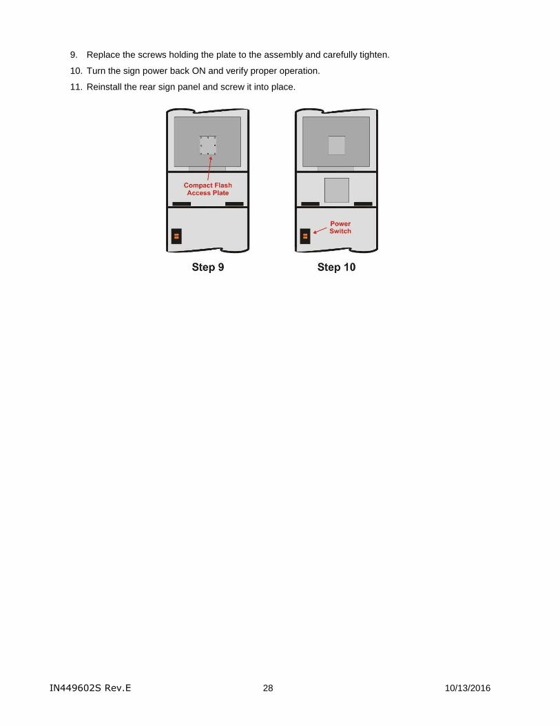
9. Replace the screws holding the plate to the assembly and carefully tighten.
10. Turn the sign power back ON and verify proper operation.
11. Reinstall the rear sign panel and screw it into place.

IN449602S Rev.E 29 10/13/2016
Removing the Electronics
1. Remove all Torx T15 screws holding on the back panel and retain for later.
2. Turn off power to the unit by switching off the rear power switch.
3. Disconnect the power, data and fan connectors then unplug the blue network cable from the Ethernet surge suppressor located below the fans.
4. The LCD display assembly is secured to the mounting bracket from the bottom with 2 mounting screws. Remove these screws/washers and set them aside for reuse.
5. Remove the LCD display assembly by lifting it up and out of the sign cabinet.
Reinstalling the Electronics
6. Set the new LCD display assembly on top of the mounting shelf being careful not to pinch any cables coming from the back.
7. Mount the assembly by using the 2 screws/washers (from the bottom on each side).
8. Reconnect the power, data and fan connectors then insert the blue network cable into the Ethernet surge suppressor located below the fans.

IN449602S Rev.E 30 10/13/2016
9. Turn the sign power back ON and verify proper operation.
10. Reinstall the rear access panel by aligning the panel's angled slots with the mounting studs along the cladding sides and push in/down into place. Rotate the latches to lock the access panel.
Cleaning the Outdoor OCS Cabinet
Use a very mild, non-abrasive household detergent solution (ie: Dawn dish soap). Rinse with clean water and dry with a chamois or a soft cloth. Do not rub cabinet with a dry cloth or use cleaning powders, solvents, abrasives, ammonia or caustics. Avoid harsh or excessive rubbing. Note: Cleaning the OCS with a pressure washer could result in damage to the system. Any damage caused by this type of cleaning will not be covered by the warranty.

IN449602S Rev.E 31 10/13/2016
System Operation
OCS Sign Operation Overview
During the power up cycle, the OCS will perform a number of memory checks and diagnostic tests as well as display system information, configuration information and network information. The display will then begin to display a series of images that are unique to the current daypart (breakfast, lunch, dinner, etc.). When orders are entered into the appropriate order taker POS register, the OCS will begin displaying the items ordered for the customer to confirm and verify. The OCS has internal smart controls that are constantly monitoring sunlight and temperature conditions and automatically controlling the OCS to perform optimally. The system is designed such that any changes to the configuration or images and any program updates can easily be transmitted to the OCS using Everbrite's back office software. The software can also perform remote diagnostic tests and display system, configuration and network information.
Converter Box Operation
The converter box is the heart of the OCS system and has many communications and diagnostic functions. The following figure and charts describe the many indicators, ports and switches on the converter.
Converter Ports Port Type Description
To OCS Female DB-9 Data cable to the OCS
Full Test Output Male DB-9 Provides ability to test the 'From POS' and 'From PC' ports on the converter by sending out a test message and receiving OCS feedback
From POS Female DB-9 For communication with the POS system
From PC Female DB-9 For communication with an Update PC computer running Everbrite back office software.
USB Female Type B USB For communication with an Update PC computer running Everbrite back office software.
DC In - Power adapter connection provides power to the converter.

IN449602S Rev.E 32 10/13/2016
Pushbuttons Description
Partial Test By pressing and holding, performs a Partial Loopback Test for diagnostic purposes - tests converter box, data cable and OCS to make sure all devices are interconnected and functioning
Full Test By pressing and holding, performs a Full Loopback Test (with the appropriate connected cables) for diagnostic purposes – tests serial cables, converter box, data cable and OCS to make sure all devices are interconnected and functioning
Indicator Lights Color Description
Power Red Indicates physical power is present
Status Amber Indicates that converter’s firmware is operating
Tx Green Lit when data is being transmitted to the OCS
Rx Red Lit when data is being received back from the OCS
POS
(Active Mode)
Red Indicates that the POS port is connected to the OCS
PC
(Active Mode)
Red Indicates that Everbrite back office software is using the PC port to communicate with the OCS
USB
(Active Mode)
Red Indicates that Everbrite back office software is using the USB port to communicate with the OCS
Partial Test Amber Indicates that a Partial Loopback Test is in progress
Pass
(Loopback Test)
Green Indicates that the current, active Loopback Test has passed
Fail
(Loopback Test)
Red Indicates that the current, active Loopback Test has failed
Full Test Amber Indicates that a Full Loopback Test is in progress

IN449602S Rev.E 33 10/13/2016
Appendices
Appendix A: OCS Install and Dimensional Drawing

IN449602S Rev.E 34 10/13/2016
Appendix B: Ethernet Connector Crimping Instructions
Below are detailed crimping instructions for Everbrite Ethernet RJ-45 connectors. Note that crimping tools for 8-wire RJ-45 connectors are available from electrical and computer supply stores.
1. Cut the outer jacket of the Ethernet cable about 2” from the end. This will give you room to work with the wires. Separate the wire pairs and align them according to the colors indicated. Begin flattening the wires into a ribbon so that it will easily slip into the connector and into the individual channeled areas.
2. Once you have all the wires aligned and ready to insert, you must trim them to ½" in order to have as little “untwisted” wire in the connector as possible.
3. Insert the wires into the connector making sure that each wire goes into the appropriate channel and extends all the way to the end of the connector underneath the gold crimping area to obtain a good crimp.
4. Press the cable and jacket into the connector firmly so that the jacket will be crimped by the plastic wedge near the rear of the connector. Insert it into the crimping tool and crimp the cable once and re-crimp it a second time to be sure all the connections are tight.
5. Pull on the cable to verify a good crimp has been made and if not then cut the connector off and start process over to obtain a tight crimp and connection.

IN449602S Rev.E 35 10/13/2016
Appendix C: Specifications
Utilizes Everbrite’s high quality, super-bright LCD backlight rated at 50,000 hours which offers optimal visibility even in direct sunlight
Unit displays orders (line items, price, tax and total) and promotional graphics
Unit continuously monitors ambient light and adjusts display brightness
Units are designed and sealed for all outdoor weather conditions with an operating range of -40 to 122 F (-40 to 50 C)
Thermostatically controlled “silent” fans are utilized to cool the unit’s electronics
Thermostatically controlled heater for cold weather operation
The display is designed with vandal resistant laminated glass and is fully enclosed in a high quality aluminum housing
Full control of graphics can be performed in a centralized or non-centralized method
Maximum current draw of unit is 1.5A at 120VAC / 60HZ
Everbrite UL file is #E6733
Average life expectancy of 5 years if used within the conditions described in our warranty
Back panel secured by Torx T15 security screws

IN449602S Rev.E 36 10/13/2016
Appendix D: Warranty Everbrite warrants the 6.x LCD Order Confirmation System (“Product”) against defects in workmanship or materials for a period of thirty six (36) months from the date of shipment. This limited warranty covers parts which are proven to be defective at the time of manufacture. During the warranty period, defective components may be replaced or repaired at Everbrite’s discretion. PROCEDURE TO REQUEST WARRANTY SERVICE 1) Contact Everbrite’s Technical Support Department at (888) 877-3092 to report a defective condition. Please have the unit’s serial
number available and include information on the store’s location, store number or code, and on-site contact information.
2) Everbrite’s Technical Support Representatives will make every effort to diagnose and trouble-shoot reported problems over the phone.
3) Should the problem be tentatively determined to be defective component or part, a return “Call Tag” will be issued. Replacement components will be shipped to the customer, along with all packing materials and shipping labels required to return the defective components. Everbrite will be responsible for the prepaid UPS Ground shipping charges.
4) Everbrite will invoice customer for replacement components upon shipment. It is the customer’s responsibility to return defective components to Everbrite within 10 business days in order to be eligible for full credit of replacement component invoice(s). Failure to return defective components within the specified time frame may result in customer payment responsibility for full replacement component invoice costs and/or may void all warranties.
5) The customer is responsible for shipping the Product back to Everbrite’s factory using the above #3 referenced packaging materials. Failure to use provided packaging materials may void warranties.
6) Upon receipt, Everbrite will inspect the product and make a determination of warranty coverage. Should Everbrite determine the product is not defective, the customer may be charged associated freight costs and a nominal inspection/re-stocking fee.
PROVISIONS/EXCLUSIONS OF WARRANTY The three year limited warranty does not cover the following conditions:
Damage or defects caused by the failure to provide a suitable and responsible installation environment for the product
Damage caused by impact from other objects, vandalism, damage or defects resulting from acts of nature, misuse, abuse, mishandling, misapplication or faulty wiring
Damage or defects caused by disturbances or surges in the electrical service; unauthorized attachments, alterations or modifications; or improper maintenance
Everbrite will not accept any responsibility for a unit that is moved from one location and re-installed at another, unless Everbrite is contracted to handle the move.
On-site maintenance or repair services
Installation labor
Under no circumstances shall Everbrite or our installers be liable for any special, incidental, or consequential damages based upon breach of warranty, breach of contract, negligence, strict liability, or any other legal theory. Such damages include, but are not limited to, loss of profits, loss of revenue, loss of data, loss of use of the Everbrite product or any associated or connected product or equipment, cost of capital, cost of substitute or replacement equipment, facilities or services, down time, purchaser’s time, or the claims of third parties.
DISCLAIMER OF WARRANTIES The warranties stated above are the only warranties applicable to this product. All other warranties express or implied (including all implied warranties of merchantability or fitness for a particular purpose), are hereby disclaimed. No oral or written information, or advice given by Everbrite, its agents or employees, shall create a warranty or in any way increase the scope of this warranty. In no event shall Everbrite’s liability exceed the original price paid for the product. This limited warranty applies to the Continental United States and Canada. Rev. 4/14/2011 24 MONTH EXTENDED WARRANTY OPTION At the time of original purchase of an Everbrite 6.x LCD Order Confirmation Board, customer may elect to extend the Standard 36 Month Limited Warranty by an additional 24 Months (60 Months Total) for an additional $700.00 fee. Audio is not included with the OCS. If an existing speaker/microphone will be used in the new Everbrite OCS, and the audio cable is already run to the same foundation the new OCS unit will be mounted on, as a courtesy, the Everbrite installer will transfer the speaker/ microphone from your existing product to your new Everbrite OCS. However, Everbrite is not liable for any audio quality issues. The customer is responsible for resolving any audio issues with the appropriate audio vendor.