organisation europ enne pour la recherche · pdf fileeuropean organization for nuclear...
TRANSCRIPT

CERN–2006–01320 November 2006
ORGANISATION EUROPÉENNE POUR LA RECHERCHE NUCLÉAIRE
CERN EUROPEAN ORGANIZATION FOR NUCLEAR RESEARCH
HIE-ISOLDE: the technical options
Editors: M. LindroosT. Nilsson
GENEVA2006

CERN–700 copies printed–November 2006

Abstract
The ISOLDE facility at CERN has a long and successful tradition of continuous development and growthin order to meet the scientific requests from the user community. The current situation continues this habitand several projects to increase the scientific scope of the facility through technical developments are underway or envisaged within the medium-term future planning. These developments will result in a transformedfacility with the label HIE (High Intensity and Energy)-ISOLDE where the intensity, quality, and energy rangeof the secondary beams will be substantially improved. They are largely in line with the necessary technicaldevelopments towards the future EURISOL facility. This report summarizes these development projects.
iii


Preface
The decision to build the ISOLDE facility at CERN was taken in 1964 by CERN Council. The facility has gonethrough many phases and upgrades over the years to assure a physics programme at the forefront of the field.
This document describes the technical options for the next upgrade of the ISOLDE facility. The differentparts chosen for further studies were selected taking advice from the User community through the ISOLDEand Neutron Time of flight experiments Committee (INTC) review of the CERN nuclear physics programmeat the Nuclear Physics and Astrophysics at CERN (NuPAC) meeting held from 10 to 12 October 2005. Theensuing document is the result of first technical studies by the ISOLDE technical team. The standing group forthe upgrade of ISOLDE has prioritized the items and a proposal has been advanced by the CERN managementto Council during the autumn of 2006 for the high-priority part of this upgrade.
The editors want to thank all the contributing authors for their input. Special thanks go to Tony Gorton([email protected]) who has done the copy-editing of the report.
Mats Lindroos
v

vi

Contents
PrefaceMats Lindroos . . . . . . . . . . . . . . . . . . . . . . . . . . . . . . . . . . . . . . . . . . . . . . . . . . . . . . . . . . . . . . . . . . . . . . . . . . . . . . . . . . v
Acronyms and abbreviations . . . . . . . . . . . . . . . . . . . . . . . . . . . . . . . . . . . . . . . . . . . . . . . . . . . . . . . . . . . . . . . . . . . . . viii
Introduction and executive summaryThomas Nilsson and Mats Lindroos . . . . . . . . . . . . . . . . . . . . . . . . . . . . . . . . . . . . . . . . . . . . . . . . . . . . . . . . . . . . . . . 1
Perspectives for increased proton intensity for ISOLDE — HIP report excerpts . . . . . . . . . . . . . . . . . . . . . . . . . . 4
Targets, electrostatic accelerators and target area issues related to proton beam intensity upgrade of theISOLDE facility
Jacques Lettry and Richard Catherall . . . . . . . . . . . . . . . . . . . . . . . . . . . . . . . . . . . . . . . . . . . . . . . . . . . . . . . . . . . . 14
Baseline design of a solid neutron converter driven by 160 MeV protonsYacine Kadi and Adonai Herrera-Martınez . . . . . . . . . . . . . . . . . . . . . . . . . . . . . . . . . . . . . . . . . . . . . . . . . . . . . . . 21
ISOLDE laser ion source — status and developmentValentin Fedosseev . . . . . . . . . . . . . . . . . . . . . . . . . . . . . . . . . . . . . . . . . . . . . . . . . . . . . . . . . . . . . . . . . . . . . . . . . . . . . 36
Radiation protection issues for HIE-ISOLDEAlexandre Dorsival and Thomas Otto . . . . . . . . . . . . . . . . . . . . . . . . . . . . . . . . . . . . . . . . . . . . . . . . . . . . . . . . . . . . 43
Mass separators and beam transportTim Giles . . . . . . . . . . . . . . . . . . . . . . . . . . . . . . . . . . . . . . . . . . . . . . . . . . . . . . . . . . . . . . . . . . . . . . . . . . . . . . . . . . . . . 52
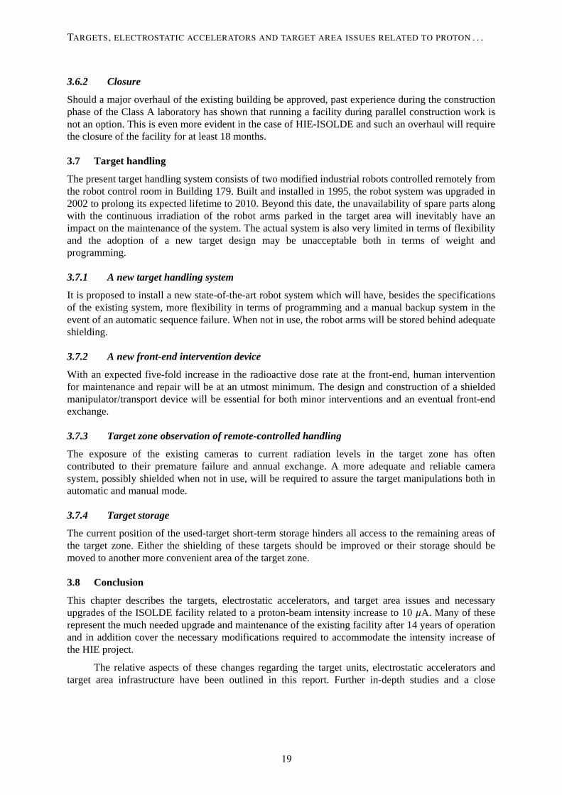
ISCOOL project: cooling and bunching RIBs for ISOLDEIvan Podadera Aliseda . . . . . . . . . . . . . . . . . . . . . . . . . . . . . . . . . . . . . . . . . . . . . . . . . . . . . . . . . . . . . . . . . . . . . . . . . 57
REX-ISOLDE low-energy stageFredrik Wenander . . . . . . . . . . . . . . . . . . . . . . . . . . . . . . . . . . . . . . . . . . . . . . . . . . . . . . . . . . . . . . . . . . . . . . . . . . . . . . 73
REX-ISOLDE LINAC upgrades: normal-conducting optionThomas Sieber and Didier Voulot . . . . . . . . . . . . . . . . . . . . . . . . . . . . . . . . . . . . . . . . . . . . . . . . . . . . . . . . . . . . . . . . 83
REX-ISOLDE LINAC energy upgrade: superconducting optionMatteo Pasini . . . . . . . . . . . . . . . . . . . . . . . . . . . . . . . . . . . . . . . . . . . . . . . . . . . . . . . . . . . . . . . . . . . . . . . . . . . . . . . . . . 93
vii

Acronyms and abbreviations
AB Accelerators and Beams Department AB/ATB Accelerators and Beams Department—Areas, Targets & Beams group AD Antiproton Decelerator ASPIC Apparatus for Surface Physics and Interfaces at CERN BEN.MQ40, 50, 60 Part of the beam transport system in the ISOLDE Radioactive Beam Experiment CA0 Part of the central beam line distribution system at ISOLDE CB0 Part of the central beam line distribution system at ISOLDE CKM Cabibo–Kobayashi–Maskawa matrix CNGS CERN Neutrinos to Gran Sasso COLLAPS Collinear Laser Spectroscopy experiment CSNSM Centre de Spectrométrie Nucléaire et de Spectrométrie de Masse, Orsay, France CVC Conserved Vector Current CVL Copper Vapour Laser DARESBURY Daresbury Laboratory of the CCLRC, UK DC Direct Current, here in the meaning continuous current EBIS Electron Beam Ion Source EBIT Electron Beam Ion Trap ECR Electron Cyclotron Resonance ECRIS Electron Cyclotron Resonance Ion Source EURISOL European Isotope Separation On-Line Radioactive Ion Beam Facility EURISOL-DS European Isotope Separation On-Line Radioactive Ion Beam Facility Design Study EURONS Integrated Infrastructure Initiative for European Nuclear Structure Research EURONS JRA Integrated Infrastructure Initiative for European Nuclear Structure Research Joint Research Activity FAIR-NUSTAR Facility for Antiproton and Ion Research, International Nuclear Structure and Astrophysics Community FWHM Full-Width Half-Maximum FLUKA A fully integrated particle physics Monte Carlo simulation package FNBS Fixed Needle Beam Scanner FRM 11 Munich High Flux Reactor, Germany FTE Full Time Equivalent (used to estimate manpower needs) FUG HCN 7E High-voltage power supply from FUG GANIL Grand Accélérateur National d’Ions Lourds, Joint IN2P3 and CEA Physics laboratory in Caen, France GeV Giga electronvolt GHM General-purpose separator High Mass beam line GLM General-purpose separator Low Mass beam line GPS General-Purpose Separator GSI Heavy-Ion Research Centre, Darmstadt, Germany HIE High Intensity and Energy HIP High Intensity Proton HITRAP An ion trap facility for experiments with highly-charged ions HRS High-Resolution Separator HV High Voltage HVR High-Voltage Room ICP ISOLDE Consolidation Project IH Interdigital H structure (type of cavity for linac)
viii

IHS.MQ90, 100, 110 Elements in the REX linac IMME Isobaric-Multiplet Mass Equation INC Intra-Nuclear Cascade IR InfraRed or Interaction Region ISCOOL ISOLDE Cooler IS82 Completed experiment at ISOLDE, Multiphoton Ionization Detection in Collinear Laser Spectroscopy of ISOLDE Beams ISOGPS Proton beam for ISOLDE General-Purpose Separator ISOHRS Proton beam for ISOLDE High-Resolution Separator ISOL Isotope Separation On-Line ISOLDE On-Line Isotope Mass Separator ISOLTRAP Penning Trap Mass Spectrometer ISR Intersecting Storage Rings JRA LASER Joint Research Activity: LASer techniques for Exotic nuclei Research JYFL The Accelerator Laboratory of the Department of Physics of the University of Jyväskylä, Finland LA1, LA2 Spectroscopy beam lines at 60 keV in the ISOLDE hall LHC Large Hadron Collider LINAC Linear accelerator LMU Ludwig-Maximilian University, Munich, Germany LORASR Longitudinal and Radial Beam Dynamics (program code) MAFF Munich Accelerator for Fission Fragments, Germany MAFIA A multi-purpose ECAD system designed to solve all kinds of electromagnetic problems from CST MeV Mega electronvolt MLL Medizinisches Laserzentrum, Lübeck, Germany MOPA Master Oscillator Power Amplifier, a laser system consisting of a seed laser and a laser amplifier for boosting the output power MPI-K Max Planck Institute for Nuclear Physics, Heidelberg, Germany Nd: YAG neodymium-doped yttrium aluminium garnet laser Nd: YLF neodymium-doped yttrium lithium fluoride laser NEG Non-Evaporable Getter pump NICOLE Nuclear Implantation Cold On Line Equipment, low-temperature nuclear orientation experiment at CERN NTOF Neutron Time Of Flight experiment at CERN NuPECC Nuclear Physics European Collaboration Committee OPO Optimal Parametric Oscillator PHOENIX-ECRIS Electron Cyclotron Resonance Ion Source from Pantechnic, France PS Proton Synchrotron PSB Proton Synchrotron Booster PSB-ISOLDE Proton Synchrotron Booster ISOLDE facility Q Charge of ion REX Radioactive Beam Experiment REXEBIS Radioactive Beam Experiment Electron Beam Ion Source RF Radio Frequency RFQ Radio Frequency Quadrupole RFQCB Radio Frequency Quadrupole Ion Cooler and Buncher RIB Radioactive Ion Beam RILIS Resonant Ionization Laser Ion Source Rn radon RNB Radioactive Nuclear Beams
ix

RP Radiation Protection SC Safety Commission SC-IE Safety Commission Integrated Safety and Environment unit SC ISOLDE-3 Synchrocyclotron ISOLDE 3 facility SC-RP Safety Commission Radiation Protection unit SIMION Software package for charged particle optics simulation SM Standard Model SPIRAL Système de Production d’Ions Radioactifs en ligne, isotope separation on-line facility at the GANIL Laboratory, Caen, France SPL Superconducting Proton Linac SPS Super Proton Synchrotron SSL Solid-State Laser TARGISOL-EU EU supported study for Optimized release from ISOL targets Th-C thorium carbide TITAN TRIUMF’s Ion Trap for Atomic and Nuclear science TOF Time of Flight TRADE TRIGA Accelerator-Driven Experiment TRAP/EBIS Penning Trap and Electron Beam Ion Source at the radiactive beam experiment at ISOLDE TRIGA General Atomics’ TRIGA® nuclear reactor program TRIUMF National Laboratory for Particle and Nuclear Physics, Vancouver, Canada UNILAC Universal Linear Accelerator U-C uranium carbide
x

1 Introduction and executive summary Thomas Nilsson and Mats Lindroos
The ISOLDE facility has existed as a concept for four decades, after the decision in 1964 by the CERN management to construct the first radioactive beam facility at CERN. Throughout its various apparitions, the facility has been steadily increasing its scientific scope and user basis, and has been one of the emblematic installations leading to the current general recognition of the potential of research with radioactive beams. The last incarnation of the ISOLDE facility commissioned in 1992, PSB-ISOLDE, was largely motivated by the possibility of post-accelerated radioactive beams. Since 2001, this has been achieved through the addition of the REX-ISOLDE post-accelerator.
Several science planning organs [1–3] have highlighted that radioactive beam physics opens unprecedented possibilities in nuclear structure and astrophysics research, and that new and developed experimental facilities are needed to exploit these possibilities. In the European context, NuPECC has recommended that two complementary facilities be constructed [4]: FAIR-NUSTAR [5] and EURISOL [6], using the techniques of in-flight separation and ISOL-method, respectively. The EURISOL facility is slated to be a considerably upgraded version of the CERN-ISOLDE facility, able to deliver radioactive beams of 2–3 orders of magnitude higher intensity than today. This necessitates a proton driver accelerator capable of delivering 1–2 GeV protons with a beam power of 5 MW. The planned SPL Linac [7], which is a prerequisite for LHC luminosity upgrades but also for neutrino superbeams, ‘beta beams’ or the muon neutrino factory, has the optimal parameters for an advanced ISOL facility. Several sites are suited to host EURISOL, but owing to the evident technical and scientific synergies, CERN might emerge as the obvious choice.
However, as also recommended by NuPECC, the realization of EURISOL is still to be seen in a long-term perspective and exploitation and further developments of the existing RIB facilities are required. In the case of ISOLDE, a vigorous upgrade programme is planned that will transform the facility into High Intensity and Energy (HIE-ISOLDE) where the secondary beam intensities and the energy range attainable will be substantially improved. These developments are largely in line with necessary technical developments towards EURISOL. Thus to further exploit the potential of the existing facility, the Standing Group for Upgrade of the ISOLDE Facility was formed in 2002, based on a mandate from the then CERN Directors of Fixed-target physics and Accelerators. This group oversees and prioritizes the various technical developments, and the current report is meant as a tool in this process.
It is clearly recognized that user-demand-driven facility developments have historically been the main key to the success of ISOLDE, and that this has to be a continuous process. The continuously improved beams have attracted an increasing user community over the years. However, there is not only one sole parameter that is requested by the experimental collaborations, but several, and these are partly self-contradictory. The requests concern higher intensity, new isotopes/elements, beam purity, beam emittance, time structure, charge state, higher and lower beam energy; and the routes to these improvements are manifold.
The available intensity of radioactive ions to an experiment depends on a large number of factors (production cross-section, decay losses, diffusion and effusion constants in the production target, ion source efficiency, and ion beam transmission). For a post-accelerated beam in REX-ISOLDE, further losses have to be taken into account (efficiency and decay losses in the trapping and charge breeding phases, intensity in the chosen charge state, transmission) that vary strongly from element to element and the various isotopes. Increased intensity of a specific element does not only mean that the measurements can be performed in less time or to a higher statistical precision, but also that further, more exotic isotopes can become within reach for the experiments.
1

1.1 Increasing intensity, purity, and number of available radioactive beams
The most straightforward route to higher secondary beam intensities is to increase the primary proton beam intensity. The ISOLDE facility is currently coupled to the PS Booster synchrotron which can deliver a maximum beam current of 4 μA on the production targets. During operation until 2005, the effective current delivered to ISOLDE has been 1.92 μA due to sharing with other programmes. The prospects for proton beam availability in the coming years and increasing the proton intensities along the full injector chain at CERN has recently been reviewed by the High Intensity Proton (HIP) working group within the AB Department. Chapter 2 contains ISOLDE-relevant excerpts of their report, where the two main paths for increasing the average beam current available for ISOLDE are faster cycling of the PSB and the addition of a new injector, Linac-4.
The target and ion source system is a key link in the production of radioisotopes, and Chapters 3 and 4 sketch necessary R&D in order to handle increased primary beam intensities and to further increase the production yield and reach new elements and/or isotopes through tailored engineering. Increasing primary beam intensities implies new challenges concerning radioprotection and Chapter 6 summarizes the necessary actions in this respect.
The Resonant Ionization Laser Ion Source (RILIS) has proven to be an outstanding tool in selectively ionizing the desired element with, in most cases, the highest efficiency attainable. However, the set-up, optimization and running of the RILIS is still complex, and constitutes an experiment within the experiment. Chapter 5 describes the perspectives of upgrading the system in order to improve its scope while facilitating its operation.
The mass separation and the beam transport efficiency to the experiment are further crucial factors in achieving maximum beam intensity and purity. Ideas for improving the mass selectivity of the separators and the throughput by modifications of the beam transport system are described in Chapter 7, and Chapter 8 describes the envisaged developments concerning cooling, bunching, and charge breeding of ions before post-acceleration.
1.2 Improving beam characteristics
The low-energy radioactive beams from ISOLDE are, because of the production method, pseudo-continuous and have a relatively large emittance; moreover, the ions are singly charged. These circumstances can pose severe limitations on the possible experiments. The ISCOOL radiofrequency cooler and buncher described in Chapter 8 will provide low-emittance, low-energy beams to a large range of experiments. Collinear laser spectroscopy with completely new precision will be made possible by the small energy spread and time-tagged decay studies; improving the signal-to-noise ratio can be performed using bunched beams of the most exotic species.
1.3 Increasing the beam energy range
The first-generation experiments performed at REX-ISOLDE have demonstrated the potential of reactions around the Coulomb barrier using radioactive beams. However, the scientific scope can be drastically enlarged if the energy range is increased. Two options for increasing the energy are discussed in the report, a normal-conducting option described in Chapter 10 and a superconducting option in Chapter 11. With increasing energy, heavier nuclei and further classes of reactions can be utilized (see Fig. 1.1). Furthermore, enlarged dynamic energy range permits optimizations for each case with respect to cross-section and open reaction channels, e.g., Coulomb excitation experiments can be performed at the highest ‘safe’ energy still below the Coulomb barrier.
The energy range between the pure ISOL beam (60 keV) and the lowest possible extractable beam energy from REX-ISOLDE (300 keV/u) is also of major interest for astrophysically relevant reactions and condensed matter research. Combining highly charged ions from charge-breeder ion sources like the existing REXEBIS and PHOENIX ECRIS described in Chapter 9 with a moderate
THOMAS NILSSON AND MATS LINDROOS
2

post-acceleration by electrostatic means, a small RFQ structure or by deceleration in a superconducting linac would yield high-intensity beams in this energy domain.
Fig. 1.1: The attainable range of isotopes at REX-ISOLDE reaching the Coulomb barrier for symmetric reactions.
References [1] NuPECC Report, NuPECC Long Range Plan 2004: Perspectives for Nuclear Physics Research
in Europe in the Coming Decade and Beyond (2004), http://www.nupecc.org/pub/lrp03/long_range_plan_2004.pdf
[2] The OECD Megascience Forum, Report of the Working Group on Nuclear Physics, 1999, http://www.oecd.org/dataoecd/23/62/2102613.pdf
[3] The DOE/NSF Nuclear Science Advisory Committee, Opportunities in Nuclear Science—A Long-Range Plan for the Next Decade, 2002, http://www.sc.doe.gov/henp/np/nsac/docs/LRP_5547_FINAL.pdf
[4] Roadmap for Construction of Nuclear Physics Research Infrastructures in Europe, 2005, http://www.nupecc.org/pub/NuPECC_Roadmap.pdf
[5] An International Accelerator Facility for Beams of Ions and Antiprotons—Conceptual Design Report, GSI, 2003, http://www.gsi.de/GSI-Future/cdr/
[6] The EURISOL Report, ed. J. Cornell, GANIL, 2003, http://www.ganil.fr/eurisol/Final_Report.html
[7] R. Garoby, A new proton injector at CERN, AB-Note-2003-048 (SPL), Geneva, 2003.
2.2 MeV/u
A < 45
3.1 MeV/u
A < 85
4.3 MeV/u
A < 145
INTRODUCTION AND EXECUTIVE SUMMARY
3

2 Perspectives for increased proton intensity for ISOLDE — HIP report excerpts The High Intensity Proton working group (HIP) within the AB Department was formed in order to ‘collect the needs of the various user communities, evaluate the benefits of the possible improvements and elaborate a preferred long-term scenario of the CERN accelerator complex. Short-term first priority steps had to be proposed, in line and consistent with the long-term scenario’. The conclusions are summarized in the report CERN-AB-2004-022 OP/RF [1], edited by M. Benedikt and R. Garoby and here only excerpts of the report, relevant for ISOLDE, will be repeated. The running of ISOLDE at the technical limit of 10 μA has radiation protection implications discussed in Chapter 6 and would require important changes at ISOLDE, e.g., changes to targets, target area and target handling system as described in Chapter 3. The implementation of the 900 ms cycling for the booster which is discussed in the text is not yet approved and can not be implemented before 2008. Except for minor rewriting to obtain language cohesion, no changes to the text have been undertaken.
2.1 Physics request
2.1.1 ISOLDE (short term)
ISOLDE operation does not generally interfere with high-energy physics, using PSB cycles that can not be exploited by the PS (case of PS cycle longer than one basic period). The nominal request is for 50% of the PSB cycles, which corresponds to an average of 1350 cycles/hour. At the maximum intensity of 3.2 × 10¹³ protons per pulse (ppp), the average beam current delivered to ISOLDE is then 1.92 μA.
2.1.2 ISOLDE (medium term)
The user community is expected to get larger and the proton flux has to grow and be brought as close as possible to the technical limit of 10 μA of the present experimental zone.
2.2 Performance of the accelerator complex
The only direct physics client of the PSB is the ISOLDE facility. The figure of merit for ISOLDE operation is the average number of available PSB cycles and the official request amounts to a minimum of 50% of the yearly cycles. This corresponds to an average of 1350 PSB cycles/hour of PSB operation for ISOLDE. Table 2.1 compares requested and available cycles for ISOLDE for the period 2006 to 2010.
Table 2.1: PSB cycles for ISOLDE operation in 2006, 2007 and 2010
Year PSB physics operation [hours]
PSB cycles to ISOLDE [%] [cycles/h]
PSB cycles requested [%] [cycles/h]
2006 4500 48 1296 50 1350
2007 5400 45 1215 50 1350
2010 5400 47 1269 50 1350
As can be seen from Table 2.1, the ISOLDE physics request can be nearly fulfilled in the period 2006 to 2010. However, this is not fully satisfying, especially since the ongoing ISOLDE upgrade programmes will eventually lead to an increase of the request by a factor of five.
4

The overall conclusion is that the CERN accelerator complex, with the already ongoing improvements, can not provide all the requested beams in the period 2006 to 2010 in the assumed operational scenario. With the present capabilities of the accelerator complex, any wishes for higher beam availability or upgrading of CNGS and ISOLDE performance cannot be fulfilled. The production of the ultimate LHC beam is also not feasible with the currently used scheme.
2.3 Upgrades for radioactive ion beams
2.3.1 Present status and upgrade planning of the ISOLDE facility
The intensity limit for the present ISOLDE facility is determined by the radioprotection for target stations, and estimated at 10 μA [2], [3].
The production of the 1.4 GeV proton beam for ISOLDE involves only the Linac2 and the PSB machines. The present CERN commitment towards ISOLDE is based on a number of ‘shifts’ per year, corresponding to about 50% of the total number of PSB cycles and was usually fulfilled during the last years. With the PSB repetition time of 1.2 s and considering 90% beam availability this translates to 1350 pulses/hour. Multiplying this figure by the nominal PSB ISOLDE intensity of 3.2 × 10¹³ ppp gives an average current of 1.92 μA usually available for ISOLDE [4].
The demand coming from the ISOLDE community for the period 2006–2010 is for an increase of this figure up to the target limit of 10 μA, i.e., a factor of ~5. The present limitation in average current comes from both the maximum proton intensity that can be produced and the number of PSB pulses that are available for ISOLDE. These two points are therefore the key issues for an upgrade analysis.
2.3.2 Beam intensity limitations and improvement scenarios
The main limiting factor for the proton beam intensity that can be provided by Linac2 and PSB is the excessive incoherent space-charge tune shift that occurs at 50 MeV injection into the PSB. With an intensity of around 1 × 10¹³ protons per PSB ring, the vertical space-charge tune spread during RF capture exceeds 0.5 and the combination of several techniques is required to avoid large beam losses and to make high-intensity operation possible.
A horizontal multiturn scheme (10–13 turns) is used to inject the Linac2 beam into the PSB. To make full use of the available aperture, coupling of the transverse planes is applied during injection in order to transfer some of the horizontal oscillation into the vertical plane. Already during the injection process, the main magnetic field is ramped to accelerate the beam out of the space-charge regime as quickly as possible. A dual harmonic (h = 1 and h = 2 in anti-phase) RF system is employed to flatten the bunches during the capture process and the early acceleration phase to improve the bunching factor thereby reducing the incoherent space charge tune spread of the beam. Nevertheless a sophisticated resonance compensation scheme is needed to avoid the destructive effect of transverse betatron resonances up to third order. All these techniques have been studied and optimized over the last years. Very little margin is left for further improvements and no significant increase in beam intensity can be expected with the present operation conditions.
The only straightforward way to significantly improve the PSB beam intensity is to attack the problem directly at its roots, i.e., to reduce the space-charge tune spread at injection by increasing the injection energy. The space-charge tune shift is inversely proportional to βγ 2, and the experience of other laboratories having increased their linac energy confirms that the final accumulated intensity is roughly proportional to βγ
2 at injection. The Fermilab linac upgrade (1993, 200 to 400 MeV corresponding to a factor 1.7 in βγ 2) opened the way for an increase of the booster intensity from 3 × 10¹² to 5.5 × 10¹² protons per pulse [5].
PERSPECTIVES FOR INCREASED PROTON INTENSITY FOR ISOLDE — HIP REPORT EXCERPTS
5

Taking the requirement to make the LHC beam in a single batch as the final goal, the PSB intensity has to be increased by a factor two. This improvement should be obtained by increasing βγ 2 at injection by a factor two, i.e., by increasing the linac energy from the present 50 MeV up to 160 MeV. If the linac is upgraded, then it is almost mandatory to change the particle type from protons to H– at the same time. This means to strongly modify the PSB injection area, but the advantages of a modern charge-exchange injection in terms of beam loss reduction, phase space painting options and emittance control clearly justify the investment. Simulations of 160 MeV H- injection and accumulation in the PSB are in progress, and present results confirm the expected gain in intensity [6], [7].
The option of increasing the energy of Linac2 was considered but finally discarded owing to the limited energy achievable in the available space at the end of the linac, about 20 m. Using standard tanks at 202 MHz, only 80 MeV could be reached, at a cost of about 30 MCHF (P+M). The limited increase in PSB intensity would present only a minor interest for ISOLDE, and no significant advantages for the other users [8]. Higher gradients could be achieved by linac tanks at double frequency (405 MHz), allowing to reach about 100 MeV. However, the cost would be higher, on account of the completely new RF system to be designed and built, and the gain still marginal. Structures at higher frequency and gradient can not be used because of the low transfer energy.
The preferred solution is to build a new linac injector. Being the fourth linac to be built at CERN, the latter would naturally be called Linac4. This option has been recently studied in detail as an outcome of the SPL study. The energy of the original SPL room-temperature injector has been increased from 120 to 160 MeV, and its design can be directly used for the Linac4 [9]. The new linac would be housed in the PS South Hall, where the required 100 m space and the infrastructure (water, electricity, etc.) are largely available, and its beam would go to the PSB in a line parallel to the existing LEIR transfer line. Another factor contributing to lowering the construction cost is that most of the Linac4 makes use of 352 MHz RF equipment recuperated from the LEP machine. Moreover, an RFQ injector that can be used for Linac4 will be given to CERN by the ‘Injecteur de Protons de Haute Intensité’ (IPHI) Collaboration (CEA and IN2P3), at the end of their testing period in 2006. The fact that a modern linac would profit from technologies like low-energy chopping and collimation, intended to minimize beam losses and reduce the environmental impact of high intensity operation must also be taken into consideration. The target value of 6.4 × 10¹³ ppp in the PSB (factor two with respect to present peak intensity) could be reached with a linac delivering 30 mA H- current during pulses of up to 500 μs length. The overall cost of a 160 MeV Linac4 in the PS South Hall, including the modification to PSB and the transfer line, has been estimated at 70 MCHF (P+M). Figure 2.1 shows a schematic layout of Linac4 in the South Hall.
Fig. 2.1: Layout of Linac4 in the PS South Hall
6

2.3.3 Increasing the number of PSB cycles available for ISOLDE
Currently, on average, around 50% of the PSB cycles are made available for ISOLDE and the remaining 50% correspond to beams that are sent to the PS for the various other physics programmes on the PS and SPS. Since this ratio will not significantly change in the short and medium-term future, no changes for ISOLDE can be expected with the present operating conditions (see Section 2.4).
To increase the number of available PSB cycles for ISOLDE, in a transparent way for the other physics users, the total (yearly) number of cycles has to be increased. There are two approaches: prolong the PSB operation period or increase the PSB repetition frequency. With the latter option in mind several machine developments and studies were performed in 2001 and 2002 to investigate the feasibility of decreasing the PSB repetition time (and also the Linac2 repetition time) from the standard 1.2 s to 0.6 s [10]. The choice of 0.6 s was motivated by the fact that the PSB main power supply, after major upgrading in the framework of the ‘PS for LHC project’, just allows a 1.4 GeV magnetic cycle to be performed within 0.6 s.
The outcome of the investigations was that a repetition time of 0.6 s is feasible for Linac2 with only minor modifications (the machine was initially designed for 2 Hz operation) but too demanding for the PSB, pushing several essential machine systems towards or beyond their limits. Even though all physics beams could be produced on short 0.6 s cycles with nominal performance, several systems of the PSB would not support 24 h operation with 0.6 s cycling. In particular, the main power supply transformers (r.m.s. current limited), the first and second harmonics RF systems (r.m.s. power and cooling limited) and the main magnets cooling circuit would require major upgrade or replacement. In addition, several power converters in the transfer lines PSB–PS and PSB–ISOLDE would also need replacement so that the total cost for reducing the PSB repetition time to 0.6 s would be in the order of 10 MCHF and require significant manpower investment.
The situation is fundamentally different when analysing a reduction of the repetition time to 0.9 s. In this case, all PSB systems can operate within specifications, only a single transfer line power converter needs replacement and a few others some upgrade work. The overall cost can be roughly estimated to around 1–2 MCHF and accordingly less manpower is required so that a reduction of the PSB repetition time can be considered a valid short-term upgrade possibility.
The potential gain for ISOLDE is still important. With 0.9 s repetition time instead of 1.2 s, the number of PSB cycles in a given period increases by 33%. Assuming (to first order) that the 33% additional cycles are made available for ISOLDE (i.e., the number of cycles for other users remains unchanged) the gain factor is (50 + 33)/50 = 1.66 so that instead of 1350 cycles, as at present, around 2240 cycles would be available per hour for ISOLDE.
Obviously 0.6 s repetition time would be significantly more beneficial for ISOLDE (with assumptions as above the gain factor is (50 + 100)/50 = 3.0) but it requires ten times more investment than the 0.9 s option and does not benefit other CERN users in a way comparable to the Linac4 option for example.
Results of detailed calculations are given in Section 2.4.
2.3.4 Estimate of short and medium-term ISOLDE performance
The effect of the two potential upgrades on the performance of the ISOLDE facility is analysed below. The decrease of the PSB repetition time from 1.2 s to 0.9 s is considered a short-term option that could already be effective in 2006. The intensity increase by a factor two, expected from a new Linac4 is a medium-term option and could be achieved at the earliest by 2010. Combining the two options, the overall gain for ISOLDE would be 2 × 1.66 = 3.32, i.e., the average current to ISOLDE can be estimated to reach ~6.4 μA.
PERSPECTIVES FOR INCREASED PROTON INTENSITY FOR ISOLDE — HIP REPORT EXCERPTS
7

The different scenarios are summarized in Table 2.2. The number of cycles available for ISOLDE is compatible with all other physics requirements and especially the assumed LHC and SPS operation modes (see Chapter 3). The assumed intensities per PSB pulse are 3.2 × 10¹³ ppp with Linac2, and twice more, 6.4 × 10¹³ ppp with Linac4. The ‘gain factor’ is the ratio of the expected average current and the present average current of 1.92 μA (Section 2.3.1). In the case of Linac4 upgrade, it is assumed that the LHC beam will be produced with single-batch filling of the PS instead of the currently used double-batch operation, thereby freeing some more cycles for ISOLDE during periods with LHC beam requests.
Table 2.2: Expected ISOLDE performance under various upgrade scenarios
2006 20071 2010
Scenario 1.2 s Linac2
0.9 s Linac2
1.2 s Linac2
0.9 s Linac2
1.2 s Linac2
0.9 s Linac2
1.2 s Linac4
0.9 s Linac4
PSB cycles/hour 1300 2250 1210 2110 1270 2200 1290 2240
% of PSB cycles 48 63 45 59 47 61 48 62
Protons/pulse [× 1013] 3.2 3.2 3.2 3.2 3.2 3.2 6.4 6.4
Protons/hour [× 1016] 4.2 7.1 3.9 6.7 4.1 7.0 8.3 14.1
Av. current [μA] 1.9 3.2 1.7 3.0 1.8 3.1 3.7 6.4
Gain factor 0.97 1.64 0.90 1.55 0.94 1.61 1.91 3.28 1 The figures for 2007 assume only proton operation in the SPS. In the case of ion commissioning (see Section 3.1.1), ISOLDE would benefit from periods when the SPS requires (only) ions.
The final conclusion is that reducing the PSB repetition time from 1.2 to 0.9 s is an important, cost-effective, short-term option that provides a significant gain of ~60% increase in average current (via the number of available cycles) for ISOLDE. In the medium term, another important gain of ~100% increase in average current (via peak current per pulse) can then be achieved with Linac4. Combining the two options will result in an increase of the average current by a factor ~3.3 as compared to the present situation.
2.4 Effect of upgrades on proton beam availability
The effects of some of the proposed accelerator complex upgrades on the proton beam availability for the period 2006 to 2010 are analysed here. The upgrades considered in detail are
i) Reduction of the basic period (and the Linac2 and PS Booster repetition time) from the present 1.2 s to 0.9 s or 0.6 s. Consequently the number of available PSB cycles is increased by either 33% (0.9 s) or 100% (0.6 s). A change of the basic period length also implies modifications of most of the PS and SPS cycles. The effect is, however, rather small on the SPS since the length of the SPS cycles is usually determined by the time required for the cycling and not by the injection flat bottom. More details on the effect of reduced basic period on PS and SPS cycles can be found in Ref. [11]. The beam characteristics (intensity, emittance, etc.) for all users is assumed to be independent of the basic period length.
ii) Increase of the CNGS intensity from 4.4 × 10¹³ to 7.0 × 10¹³ protons per SPS cycle. For this option it is assumed that PS and SPS high-intensity performance can be pushed by around 60% as compared to the nominal CNGS scenario. The higher intensity in the PS is achieved by using two consecutive injections from the PSB (double batch filling), similar to LHC operation [12]. Production and characteristics of the beams for all other physics
8

users are to first order identical to the nominal scenario. The main impact of this option is therefore the increased number (factor 2) of PSB cycles required for CNGS operation.
iii) A new Linac4 (160 MeV, H-) as injector for the PSB [9]. In this scenario it is assumed that the increased injection energy allows doubling the beam brightness in the PSB. Therefore the nominal (and also the ultimate) LHC beam can be produced with a single PSB pulse in contrast to the currently used double-batch scheme, thus reducing the number of required PSB cycles by a factor of two. A similar argument applies to CNGS operation, where the higher intensity (7.0 × 10¹³) can be achieved with a single PSB batch for the PS, avoiding the disadvantageous double-batch filling required for option (ii). As discussed above, it is assumed that the PS and SPS can handle the 60% increase in intensity. Finally it is expected that the PSB intensity for ISOLDE can be doubled from the nominal 3.2 × 10¹³ to 6.4 × 10¹³ ppp. All other physics beams will be produced as in the nominal scenario.
The comparison of the various upgrades is based on the operation conditions and guidelines that were defined for the performance analysis of Chapter 3 in Ref. [1]. The same supercycle compositions, user priorities and beam requests were assumed. Tables 2.3 to 2.11 summarize the beam availability for all physics users for 2006, 2007 and 2010 for the following three scenarios:
– Present operational beam characteristics (‘standard operation’).
– Increased CNGS intensity of 7.0 × 10¹³ per SPS cycle (‘CNGS double batch’).
– 160 MeV H- injection into the PSB (‘Linac4’).
Tables 2.3 to 2.5 are for the present Linac2 and PSB repetition time of 1.2 s, Tables 2.6 to 2.8 assume 0.9 s and Tables 2.9 to 2.11 are for 0.6 s.
ISOLDE performance is quoted in three different ways: pulses per hour, average percentage of PSB cycles, and average current. This is because the present way of quantifying ISOLDE performance by quoting either PSB pulses or percentage of cycles makes little sense when changing the PSB repetition time.
It should be noted that Linac4 is considered a medium-term option that will be available by 2010 at the earliest. Nevertheless, performance figures for this option are quoted for 2006 and 2007 for comparison.
Table 2.3: Beam availability in 2006 with 1.2 s PSB repetition time
Request Standard operation
CNGS high intensity Linac4
CNGS [× 1019 pot/year] 4.5 4.4 6.3 (4.5) 7.0 (4.5)
FT [× 105 spills/year] 7.2 3.3 3.0 (4.5) 3.3 (5.1)
East Area [× 106 spills/year] 1.3 1.3 1.2 1.3
nTOF [× 1019 pot/year] 1.0–1.5 1.4 1.3 1.4
ISOLDE [pulses/hour]
Average current [μA]
1350 (50%)
1.9
1300 (48%)
1.9
930 (34%)
1.3
1300 (48%)
3.7
PERSPECTIVES FOR INCREASED PROTON INTENSITY FOR ISOLDE — HIP REPORT EXCERPTS
9

Table 2.4: Beam availability in 2007 with 1.2 s PSB repetition time
Request Standard operation
CNGS double batch Linac4
CNGS [× 1019 pot/year] 4.5 4.4 6.3 (4.5) 7.0 (4.5)
FT [× 105 spills/year] 7.2 1.9 1.8 (3.3) 1.9 (3.7)
East Area [× 106 spills/year] 1.3 1.5 1.4 1.6
nTOF [× 1019 pot/year] 1.0–1.5 1.7 1.5 1.7
ISOLDE [pulses/hour] Average current [μA]
1350 (50%) 1.9
1210 (45%) 1.7
890 (33%) 1.3
1260 (47%) 1.8
SPS LHC filling cycle [s] – 21.6 21.6 18.0
SPS LHC pilot cycle [s] – 22.8 25.2 22.8
Table 2.5: Beam availability in 2010 with 1.2 s PSB repetition time
Request Standard operation
CNGS double batch Linac4
CNGS [× 1019 pot/year] 4.5 4.9 (4.5) 7.0 (4.5) 7.8 (4.5)
FT [× 105 spills/year] 7.2 3.3 (3.8) 3.0 (5.1) 3.3 (5.7)
East Area [× 106 spills/year] 1.3 1.5 1.4 1.5
nTOF [× 1019 pot/year] 1.0–1.5 1.7 1.5 1.7
ISOLDE [pulses/hour] Average current [μA]
1350 (50%) 1.9
1270 (47%) 1.8
920 (34%) 1.3
1290 (48%) 3.7
SPS LHC filling cycle [s] - 21.6 21.6 18.0
SPS LHC pilot cycle [s] - 22.8 25.2 22.8
Table 2.6: Beam availability in 2006 with 0.9 s PSB repetition time
Request Standard operation
CNGS double batch Linac4
CNGS [× 1019 pot/year] 4.5 4.2 6.3 (4.5) 6.7 (4.5)
FT [× 105 spills/year] 7.2 3.2 3.0 (4.5) 3.2 (4.8)
East Area [× 106 spills/year] 1.3 1.2 1.1 1.2
nTOF [× 1019 pot/year] 1.0–1.5 1.3 1.3 1.3
ISOLDE [pulses/hour] Average current [μA]
1350 (50%) 1.9
2250 (63%) 3.2
1850 (51%) 2.6
2250 (63%) 6.4
10

Table 2.7: Beam availability in 2007 with 0.9 s PSB repetition time
Request Standard operation
CNGS double batch Linac4
CNGS [× 1019 pot/year] 4.5 4.3 6.3 (4.5) 6.8 (4.5)
FT [× 105 spills/year] 7.2 1.9 1.8 (3.3) 1.9 (3.6)
East Area [× 106 spills/year] 1.3 1.5 1.4 1.5
nTOF [× 1019 pot/year] 1.0–1.5 1.7 1.6 1.7
ISOLDE [pulses/hour] Average current [μA]
1350 (50%) 1.9
2110 (59%) 3.0
1760 (49%) 2.5
2210 (61%) 3.2
SPS LHC filling cycle [s] – 18.9 18.9 18.9
SPS LHC pilot cycle [s] – 23.4 25.2 23.4
Table 2.8: Beam availability in 2010 with 0.9 s PSB repetition time
Request Standard operation
CNGS double batch Linac4
CNGS [× 1019 pot/year] 4.5 4.7 (4.5) 7.0 (4.5) 7.5 (4.5)
FT [× 105 spills/year] 7.2 3.2 (3.4) 3.0 (5.1) 3.3 (5.6)
East Area [× 106 spills/year] 1.3 1.5 1.4 1.5
nTOF [× 1019 pot/year] 1.0–1.5 1.6 1.5 1.6
ISOLDE [pulses/hour] Average current [μA]
1350 (50%) 1.9
2200 (61%) 3.1
1810 (50%) 2.6
2240 (62%) 6.4
SPS LHC filling cycle [s] – 18.9 18.9 18.9
SPS LHC pilot cycle [s] – 23.4 25.2 23.4
Table 2.9: Beam availability in 2006 with 0.6 s PSB repetition time
Request Standard operation
CNGS double batch Linac4
CNGS [× 1019 pot/year] 4.5 4.4 6.6 (4.5) 6.9 (4.5)
FT [× 105 spills/year] 7.2 3.3 3.1 (4.7) 3.3 (5.0)
East Area [× 106 spills/year] 1.3 1.3 1.2 1.3
nTOF [× 1019 pot/year] 1.0–1.5 1.4 1.3 1.4
ISOLDE [pulses/hour] Average current [μA]
1350 (50%) 1.9
4000 (74%) 5.7
3540 (66%) 5.0
4000 (74%) 11.4
PERSPECTIVES FOR INCREASED PROTON INTENSITY FOR ISOLDE — HIP REPORT EXCERPTS
11

Table 2.10: Beam availability in 2007 with 0.6 s PSB repetition time
Request Standard operation
CNGS double batch Linac4
CNGS [× 1019 pot/year] 4.5 4.4 6.6 (4.5) 7.0 (4.5)
FT [× 105 spills/year] 7.2 1.9 1.9 (3.5) 1.9 (3.7)
East Area [× 106 spills/year] 1.3 1.6 1.5 1.6
nTOF [× 1019 pot/year] 1.0–1.5 1.7 1.6 1.7
ISOLDE [pulses/hour] Average current [μA]
1350 (50%) 1.9
3880 (72%) 5.5
3490 (65%) 5.0
3960 (73%) 11.3
SPS LHC filling cycle [s] – 19.8 19.8 18.0
SPS LHC pilot cycle [s] – 22.8 24.0 22.8
Table 2.11: Beam availability in 2010 with 0.6 s PSB repetition time
Request Standard operation
CNGS double batch Linac4
CNGS [× 1019 pot/year] 4.5 4.9 (4.5) 7.4 (4.5) 7.8 (4.5)
FT [× 105 spills/year] 7.2 3.3 (3.8) 3.1 (5.4) 3.3 (5.7)
East Area [× 106 spills/year] 1.3 1.5 1.5 1.5
nTOF [× 1019 pot/year] 1.0–1.5 1.7 1.6 1.7
ISOLDE [pulses/hour] Average current [μA]
1350 (50%) 1.9
3960 (73%) 5.6
3520 (65%) 5.0
3990 (74%) 11.4
SPS LHC filling cycle [s] – 19.8 19.8 18.0
SPS LHC pilot cycle [s] – 22.8 24.0 22.8
2.4.1 Conclusions
The comparison between upgrades highlights that a significant increase of the SPS intensity per pulse for CNGS is a very effective way of improving the performance for CNGS and/or FT, whereas the choice of the basic period length and the PSB repetition time has no important influence on these physics users. A potential way of achieving this is to fill the PS with two consecutive PSB cycles (double-batch operation) and to improve on high-intensity operation of PS and SPS. This has unfortunately the detrimental effect of reducing the number of PSB cycles available to other users. With the present PSB repetition time of 1.2 s, ISOLDE operation would seriously suffer, as can be seen in Table 2.3 to Table 2.5, whereas for the PS (East Area, nTOF, AD) no shortage of cycles or beam availability is anticipated. The straightforward way of improving ISOLDE performance is to decrease the PSB repetition time. For a repetition time of 0.9 s (Table 2.6 to Table 2.8), ISOLDE performance will still be ~30% above request when double batch operation is used for CNGS. A further decrease of the repetition time to 0.6 s is mainly advantageous to ISOLDE which will then reach 2 or even 2.5 times the requested performance.
The installation of Linac4, as injector for the PSB, will significantly increase the proton flux for ISOLDE (~×2), and to a lesser extent, for CNGS and FT (~×1.1). For the LHC, Linac4 is also very
12

valuable for the twice higher brightness that can be achieved in the PSB. Moreover, PSB cycles are freed for other users because LHC nominal and ultimate beams and also very high intensity CNGS-type beams can be produced with single PSB batches. When combined with a shorter basic period of 0.9 or 0.6 s, Linac4 will bring the flux to ISOLDE to 3.4 or even 6 times the nominal request.
2.5 Summary of the recommendations
In the short term, to define in 2004 and start in 2005 the following three projects:
– New multi-turn ejection for the PS.
– Increased intensity in the SPS for CNGS (implications in all machines).
– 0.9 s PSB repetition time.
In the medium term, to work on the design of Linac4, to prepare for a decision on construction at the end of 2006.
In the long term, to prepare for a decision concerning the optimum future accelerator by pursuing the study of a Superconducting Proton Linac and by exploring alternative scenarios for the LHC upgrade.
References [1] M. Benedikt, K. Cornelis, R. Garoby, E. Métral, F. Ruggiero and M. Vretenar, ‘Report Of The
High Intensity Protons Working Group’, Eds. M. Benedikt and R. Garoby, CERN-AB-2004-022 OP/RF, 2004.
[2] T. Nilsson, ISOLDE Upgrade and Future Plans, HIP meeting, http://ab-div.web.cern.ch/ab-div/Projects/hip/Presentations/HIP-12Feb03-TNilsson.ppt
[3] D. Forkel-Wirth et al., Reflections on Super-ISOLDE, CERN/TIS-RP/TM/2000-18, Geneva, 2000.
[4] Addendum to the Memorandum of Understanding for the Execution of the ISOLDE Experiments at the PS-Booster, CERN, Geneva, 2004.
[5] E. Prebys, FNAL, private communication and M. Popovic, L. Allen, A. Moretti, E. McCrory, C.W. Schmidt and T. Sullivan, High Current Proton Tests of the Fermilab Linac, Linac2000 Conference, Monterey, 2000.
[6] M. Martini and C. Prior, High-intensity and High-density Charge-exchange Injection Studies into the CERN PS Booster at Intermediate Energies, to be published at EPAC 2004, Lucerne, 2004.
[7] M. Martini, Latest Results on 160 MeV H- Injection in the PSB, HIP meeting. [8] M. Vretenar, Upgrade of the CERN Linacs, HIP meeting, http://ab-div.web.cern.ch/ab-
div/Projects/hip/Presentations/HIP-12Mar03-MVretenar.ppt [9] R. Garoby, K. Hanke, A. Lombardi, C. Rossi, M. Vretenar and F. Gerigk, Design of the Linac4,
a new Injector for the CERN Booster, to be published at Linac2004, Lubeck (Germany), 2004. [10] M. Benedikt and Results of Tests for Linac2 and PSB at 600 ms, PPC meeting,
http://psdoc.web.cern.ch/PSdoc/ppc/ppc021122/ppc021122.html [11] M. Benedikt and G. Métral, Cycling of the PS Complex and the SPS: Analysis and Possibilities
for Optimisation, HIP meeting, http://ab-div.web.cern.ch/ab-div/Projects/hip/Presentations/HIP-12Feb03-MB.doc
[12] R. Cappi (editor), K. Cornelis, J.-P. Delahaye, R. Garoby, H. Haseroth, K. Hübner, T. Linnecar, S. Myers, K. Schindl and C. Wyss, Increasing Proton Intensity of PS and SPS, CERN-PS (AE) 2001-041, Geneva, 2001.
PERSPECTIVES FOR INCREASED PROTON INTENSITY FOR ISOLDE — HIP REPORT EXCERPTS
13

3 Targets, electrostatic accelerators and target area issues related to proton beam intensity upgrade of the ISOLDE facility
Jacques Lettry and Richard Catherall
3.1 Introduction
Following the naturally evolving requirements of the ISOLDE Collaboration, the ISOLDE facility develops new radioactive ion beams to extend the assortment of the 800 Radioisotope Beams (RIBs) available today. The R&D work on ion sources, new target materials, or new beam purification methods is closely related to the constant effort to improve the lifetime and reliability of the equipment.
The lifetime of ISOLDE targets at the PS booster is of the order of a million proton pulses which corresponds to a few 1019 protons. The proton beam pulsed structure is at the origin of the thermal-shock-induced material sintering and is today’s limitation to the target lifetime characterized by a drop of the radioactive ion beam yield. Independently, for high-Z target materials (U, Th, Pb, and Ta), the integrated radiation dose generated by 1020 GeV protons corresponds to the radiation hardness limit of the weakest component, namely, the vacuum vessel sealing. The average proton-beam intensity upgrade from 2 μA to 10 μA would therefore proportionally increase the frequency of changes of today’s standard targets. The setting up time (3–6 days) of a target unit would then be longer than the RIB production period and would become the limiting factor.
While the target handling is done via industrial robots, the maintenance of the equipment of the facility requires human intervention. Therefore, the radiation doses on staff must be minimized by developing maintenance-free equipment or dedicated remote-controlled handling systems.
The EURISOL-DS European project [1] is currently developing targets and target stations for orders of magnitude higher proton beam power. Evident synergies on modelling, materials development and design of remote handling equipment will be exploited.
In Section 3.2, the implications of a proton-beam intensity increase on the electrostatic accelerators are discussed; Section 3.3 deals with the necessary upgrade of the vacuum system while Section 3.4 covers the aspects of targets and ion sources. The adaptation of the facility to the radioprotection and waste disposal issues outlined in Chapter 6 of this report is considered in Section 3.6. The civil engineering is considered in Section 3.5 and target handling in Section 3.7.
3.2 Electrostatic accelerators
The so-called ‘front-end’ is composed of two vacuum sections: the electrostatic acceleration section consisting of a moveable electrode, two pairs of electrostatic deflectors and the platform supporting the remote-controlled vacuum coupling of the target unit; and the beam optics section containing an electrostatic quadrupole triplet and a Faraday cup used to monitor the total ion-beam current. Two 1000 l s–1 turbo pumps and two all-metal valves are suspended below the vacuum vessel. The front-end is supported by a vehicular chassis to ease its hands-on maintenance. It is connected to the separator beam line, inside an aluminium Faraday cage and perpendicular to the proton beam trajectory. Cables and fluids are connected to the front-end either on ground potential or from a high-voltage platform via a HT transfer tube (Boris tube).
3.2.1 Optics
With a view to minimizing the number of moving parts, and consequently the number of human interventions, the ion-beam optics will be studied with the objective of removing the extraction electrode mechanism. While this solution will minimize occasional interventions throughout the year,
14

the exchange of extraction electrode tips that are the most contaminated parts (contact dose rate of the order of 1 Sv/h) must also be addressed. The new front-ends should be designed so that interventions are reduced to an absolute minimum while the performance of the front-end, at a higher dose rate, remains constant.
3.2.2 Cabling and fluids
The insulation of all cables within the vicinity of the front-end is subject to radiation damage. All cables must be insulated with the most radiation-resistant material possible; provisions should be made for the quick exchange of cables in the event of a breakdown. The same quick exchange practice should also apply to all compressed-air and water-cooling components and distribution. In the event of a complete front-end exchange, all connections should be rapidly accessible. Ideal on paper, remote-controlled connections should be designed such that their own maintenance does not add to the dose.
3.2.3 Alignment
To limit the time spent in situ while aligning a new front-end, a new and faster protocol should be devised. The front-end should be pre-aligned on a reference jig prior to installation. External alignment points should then be used for verification while the final beam axis adjustment is obtained by electrostatic deflectors.
3.2.4 Target coupling
The existing remote target coupling system is very sensitive to mechanical tolerances. At present, the electrical, fluid, and vacuum connections are simultaneously provided and coupled remotely by one compressed-air piston. In the event of a slight misalignment, the system is jeopardized during the coupling phase. The fact that the front-end is sealed with a mechanical shutter sets stringent safety requirements on those who need to intervene in case of potential hazardous contamination. Once this mechanical shutter is open, experience has shown that volatile contamination is prone to migrate from the unsealed on-line front-end. The vacuum coupling could be dissociated from the mechanical coupling of electrical and fluid connectors. This would also address the risk of pumping on a large vacuum leak that rapidly fills the exhaust-gas storage tanks.
3.2.5 Vacuum equipment
Access to the vacuum equipment on the front-end (turbo-molecular pumps, valves, vacuum gauges, etc.) is already strictly limited on account of the ambient dose rate in the front-end Faraday cage. One proposal is to extend the vacuum pumping ducts of the front-end so as to house the vacuum equipment farther away and shielded from the main radioactive source. Owing to the confinement of the existing facility, this would imply the construction of a service gallery above the existing Faraday cage. The consequences of such a gallery are discussed in Section 3.6.1.
3.2.6 High-voltage power supply
The present pulsed 60 kV high-voltage power supplies are designed to recover to 60 kV (± 1 V) within a time interval of 6 ms [2]. Recent tests have shown that the use of a high-Z converter coupled to actinide targets producing n-rich fission isotopes [3] has already imposed limitations on the voltage recovery time due to the heavier dynamic load generated by an increased temporal ionization profile from secondary particles. Increasing the proton pulse intensity would require a full re-evaluation of the power supply design.
TARGETS, ELECTROSTATIC ACCELERATORS AND TARGET AREA ISSUES RELATED TO PROTON . . .
15

3.2.7 High-voltage transport tube
The two existing 7 metre long high-voltage transport tubes consist of an inner aluminium tube kept under high voltage, centred and separated from the external grounding tube by two Araldite insulators at either end. In 2006, after 14 years of exposure to high radiation levels, the insulators in the Faraday cages are showing signs of degradation leading to high-voltage breakdowns. Although a temporary repair is planned for the 2006/2007 shutdown period, a more reliable solution needs to be developed for the HIE-ISOLDE upgrade. In parallel, and as mentioned in Chapter 6, the HT transport tubes provide a direct pathway between the highly radioactive Faraday cage and the high-voltage power supply room. Consequently, the design of the new high-voltage transport tubes should also include dedicated shielding or chicanes and be compatible with the eventual construction of a service gallery.
3.3 Vacuum
There are many aspects to the vacuum issues in the event of an upgrade to 10 µA proton beam. These include the integrated vacuum system of the front-end, the target units, the primary pumping system, and the collection, storage, and exhaust of radioactive gases [4].
3.3.1 Front-end vacuum system
The proposal to extend the vacuum pumping ducts requires an engineering study. Pumping speed, vacuum pressures, system design and controls are only part of the extensive study.
3.3.2 Target units
The installation of metallic sealing on all feed-throughs implies an increase in the sealing pressure and non-reusability of the sealing. A major modification of the standard geometrical arrangement with repercussions on the front-end coupling is unavoidable. The engineering study should clarify within two years the constraints of a metallic and ceramics based vacuum vessel on the front-end.
3.3.3 Primary pumping system
At present, an array of four roughing pumps assures the primary pumping of both front-ends. Although reliable, it is currently located in a highly radioactive zone and is itself a strong radiation source due to the capturing of long-lived radioactive isotopes in the pump oil. These concerns must be addressed; to provide easier access, the pumping array could be situated in the same aforementioned service gallery. However, as the contamination of the pump oil requires that the oil be changed with the utmost precaution in a Class A type radioactive laboratory [5], the possibility of containing the contamination before capture by the pump oil should also be investigated.
3.3.4 Exhaust-gas storage
Currently, the exhaust gases of the primary pumps after repeated target changes are stored up to an over-pressure of 2 bar in two separate tanks approximately 3 m3 each. During the shutdown period and after a minimum of three months radioactive decay, the gases are released into the atmosphere under the supervision and monitoring of the radiation protection service. As mentioned in Chapter 6 of this report, the radiation protection service recommends that the exhaust gases should be stored at an under-pressure to minimize the consequences of accidental leakage. This would imply an increase in the number of storage tanks required to store the present quantity of exhaust gases. An increased front-end volume, more frequent target changes, and a five-fold increase in proton-beam intensity are all factors that need to be considered when dimensioning the new storage tanks.
JACQUES LETTRY AND RICHARD CATHERALL
16
3.4 Targets and ion sources
Target and ion source development will be a key issue for the HIE-ISOLDE project. Connectivity and geometry with respect to a new front-end have already been mentioned, however, emphasis should be put on improving the reliability and lifetime of target and ion-source systems and their performance.
3.4.1 Targets
The PS booster provides proton pulses of up to 3 × 10¹³ protons within 2 μs. The quasi instantaneous heating generates thermal shocks that in the past led to the destruction of the target Ta oven and today contribute to the rapid sintering of the target material [6]. By keeping the same irradiation parameters, the typical target lifetime of seven days would shorten with increased intensity. A proportional increase of the target diameter and proton-beam size leading to quadratic reduction of the temperature jump but increased target volume (and increased effusion time) may be unavoidable.
3.4.2 Transfer line, oven, and effusion
Once the target material arrangement is optimized, the desorption enthalpies define the residence time of chemicals on substrates and, therefore, the effusion time. For some of the slowly released elements, the choice of rhenium or carbon, for example, instead of tantalum as construction material for the transfer line and oven would speed up the effusion process considerably. Systematic studies of desorption enthalpies have been published and were investigated for RIB production by the TARGISOL EU-project [7].
3.4.3 Beam purification
Beam purity is an important key to the success of experiments, therefore, the suppression of easily ionized alkali isobaric contamination must be pursued. Internal drift fields for Ta targets and micro bunching increased the signal-to-noise ratio up to a factor of 5. Despite a reduction of the RILIS efficiency by at least a factor of 100, orders of magnitude improved signal-to-noise ratio are expected from electrostatic suppression of surface ionized ions. On-line tests are pending. Chemical separation of alkali elements in a quartz transfer line is a promising purification method [8]. On-line tests have demonstrated that the quartz surface keeps its properties while coupled to an out-gassing high-temperature container.
3.4.4 Ion sources
ECR ion sources for gaseous elements and RILIS dedicated ionization schemes for new elements such as mercury and gold will be developed. Systematic modelling of the plasma and beam-optics properties of existing ion sources will be undertaken. The planned measurements of emittances and efficiencies of existing and new ion source designs are the observables that will validate their simulation.
3.5 Radiation protection
3.5.1 FLUKA simulations
To fulfil the criteria highlighted in Chapter 6 of this report, a detailed FLUKA [9] simulation of the existing ISOLDE target area will define the critical issues and provide the parameters for the major changes to the existing facility.
3.5.2 Radioactive waste characterization
The estimation of the produced radioactive waste resulting from high-energy accelerators and facilities is an obligation stated in CERN’s radioprotection manual. A program is being written to follow up the
TARGETS, ELECTROSTATIC ACCELERATORS AND TARGET AREA ISSUES RELATED TO PROTON . . .
17

irradiation of ISOLDE targets and the decay of the produced radionuclei over decades. The release parameters, the ionization efficiency, and the chemical form of the released elements will be integrated to identify the final destination (target, vacuum system, separator or experiments) of specific radio-elements. The description of the full process is complex and rather than ultimate precision, the model aims at characterizing the various transport mechanisms and opening the path for specific optimizations. The final radio-isotope cartography is a vital element for the radioactive waste inventory.
3.5.3 Radioactive waste transport intermediate storage and conditioning
Irradiated targets are stored at for least four, and up to eleven months in a dedicated area located between the irradiation zone and the Class A laboratory. The irradiated targets are then transported to a remote intermediate storage for a period of 10 years and then brought back to the Class A laboratory for conditioning prior to disposal. The target handling system should be reviewed to accommodate higher activities, a remote handling procedure must be designed to operate within the Class A laboratory and a similar system must be installed at the intermediate storage location for the reception of used targets. The transport of irradiated targets between the Class A laboratory and the intermediate storage requires dedicated shielding and confinement matching today’s standards in matters of radioactive transport. The transport procedure should be executed with a minimum of human intervention.
The intermediate storage requires a dedicated aerosol monitoring system and an upgrade of the access control.
A preconditioning programme prior to shipment to the Paul Scherrer Institute for further treatment has already started at ISOLDE. Basically, the preconditioning consists of separating and identifying the different materials of a target unit, with emphasis on separating aluminium, before storing them in standard 200 l drums. Whilst after 10 years cooling this is feasible in fume cupboards with slightly radioactive low-Z targets, high-Z and more radioactive targets will have to be processed in a dedicated hot cell currently under design.
3.6 Civil engineering
An upgrade to 10 µA of proton-beam intensity will inevitably lead to civil engineering modifications of the existing facility. The proposal of an overhead service gallery, improved shielding, and the modification of the target handling system are major contributions to the final design of the future ISOLDE target area. Furthermore, owing to the higher levels of unfixed contamination, the construction of a new facility will have to abide by the Class A regulations defined by the Office Fédéral de la Santé Publique [10]. Each aspect of the infrastructure services should be identified and implemented within the new building. These include ventilation, fluids, cabling, controlled access, target handling, vacuum systems, etc.
3.6.1 Service gallery
Concerning the overhead service gallery, the issue of converting an existing tunnel to a shielded building spanning the Swiss–French border has first to be addressed. The existing earth mound will provide insufficient shielding in the event of a five-fold increase in proton-beam intensity so its replacement by shielding blocks seems unavoidable. The overhead service gallery could be incorporated into the extra shielding and at the same time, by installing a roof, the issue of activated rain water, identified in Chapter 6, could be properly addressed. Already discussed as a solution to distance vacuum equipment from the source of radiation, the option of a service gallery could satisfy similar requirements for both the front-ends and other services already housed in the target zone. This includes the primary pump array, exhaust-gas storage tanks, ventilation equipment to mention but a few.
JACQUES LETTRY AND RICHARD CATHERALL
18
3.6.2 Closure
Should a major overhaul of the existing building be approved, past experience during the construction phase of the Class A laboratory has shown that running a facility during parallel construction work is not an option. This is even more evident in the case of HIE-ISOLDE and such an overhaul will require the closure of the facility for at least 18 months.
3.7 Target handling
The present target handling system consists of two modified industrial robots controlled remotely from the robot control room in Building 179. Built and installed in 1995, the robot system was upgraded in 2002 to prolong its expected lifetime to 2010. Beyond this date, the unavailability of spare parts along with the continuous irradiation of the robot arms parked in the target area will inevitably have an impact on the maintenance of the system. The actual system is also very limited in terms of flexibility and the adoption of a new target design may be unacceptable both in terms of weight and programming.
3.7.1 A new target handling system
It is proposed to install a new state-of-the-art robot system which will have, besides the specifications of the existing system, more flexibility in terms of programming and a manual backup system in the event of an automatic sequence failure. When not in use, the robot arms will be stored behind adequate shielding.
3.7.2 A new front-end intervention device
With an expected five-fold increase in the radioactive dose rate at the front-end, human intervention for maintenance and repair will be at an utmost minimum. The design and construction of a shielded manipulator/transport device will be essential for both minor interventions and an eventual front-end exchange.
3.7.3 Target zone observation of remote-controlled handling
The exposure of the existing cameras to current radiation levels in the target zone has often contributed to their premature failure and annual exchange. A more adequate and reliable camera system, possibly shielded when not in use, will be required to assure the target manipulations both in automatic and manual mode.
3.7.4 Target storage
The current position of the used-target short-term storage hinders all access to the remaining areas of the target zone. Either the shielding of these targets should be improved or their storage should be moved to another more convenient area of the target zone.
3.8 Conclusion
This chapter describes the targets, electrostatic accelerators, and target area issues and necessary upgrades of the ISOLDE facility related to a proton-beam intensity increase to 10 µA. Many of these represent the much needed upgrade and maintenance of the existing facility after 14 years of operation and in addition cover the necessary modifications required to accommodate the intensity increase of the HIE project.
The relative aspects of these changes regarding the target units, electrostatic accelerators and target area infrastructure have been outlined in this report. Further in-depth studies and a close
TARGETS, ELECTROSTATIC ACCELERATORS AND TARGET AREA ISSUES RELATED TO PROTON . . .
19

collaboration with other CERN specialists are required to finalize the project that should be started well in advance of the eighteen months required to transform the facility.
The upgrade of the targets, front-ends, target area, and infrastructure is a project in itself to be managed in close collaboration with the radioprotection service.
A first-approach cost and manpower evaluation is estimated at 8.8 MCHF and 29 FTEs over a period of up to six years.
References [1] http://www.eurisol.org/site01/index.php [2] D.C. Fiander and A. Fowler, A 60 kV modulator for the target voltage of an on-line isotope
separator, 20th Power Modulator Symposium, Myrtle Beach, South Carolina, USA, June 1992, CERN/PS 92-38(RF).
[3] R. Catherall et al., Radioactive ion beams produced by neutron-induced fission at ISOLDE, Nucl. Instrum. Methods B204 (2003) 235–239.
[4] S. Meunier, Système vide ISOLDE, AT-VAC Technical Note 04-16, Ref: edms 537198.v2 de décembre 2004.
[5] R. Catherall et al., The radioactive laboratory upgrade at ISOLDE, CERN, Nucl. Phys. A746 (2004) 379c–383c.
[6] J. Lettry et al., Effects of thermal shocks on the release of radioisotopes and on molten metal target vessels, Nucl. Instrum. Methods B204 (2003) 251–256.
[7] http://www.targisol.csic.es/ [8] E. Bouquerel et al., Purification of a Zn radioactive ion beam by alkali suppression in a quartz
line target prototype, to be published in European Physics Journal (RNB7 proceedings) 2006. [9] www.cern.ch/fluka/
[10] Ordonnance sur l’utilisation des sources radioactives non-scellées du 21 novembre 1997 (Etat 23 décembre 1997), 814554, Switzerland (1997).
JACQUES LETTRY AND RICHARD CATHERALL
20

4 Baseline design of a solid neutron converter driven by 160 MeV protons Yacine Kadi and Adonai Herrera-Martínez
4.1 Introduction
The physics community that uses Radioactive Ion Beams (RIBs), estimated to be about 1000 in Europe alone, requires diversity of ion species, diversity of beam energy, and high beam intensities. REX-ISOLDE already provides the first of these; the aim of HIE-ISOLDE is to achieve the second and the third [1]. This requires developments in post-acceleration (the present energy restricts the application of REX to studies of light nuclei) and radioisotope selection as well as target-ion source development and charge-breeding, to cope with the increase in proton intensity expected from Linac4. In the case of HIE-ISOLDE, it would have to be fully transformed to face the new specifications. In particular, the new design would require the construction of a new proton driver such as the SPL and new target stations capable of accepting 100 μA proton beams [2] into a first-stage EURISOL [3] that would allow achieving many of its physics goals. The project aims to improve the target and front-end part of ISOLDE to fully profit from potential upgrades of the existing CERN proton injectors, e.g., faster cycling of the PS Booster and Linac4.
We present the results of recent simulations and analyses concerning the physics of the spallation target with 160 MeV proton beam energy.
4.2 Physics of the spallation target
The converter/fission target system is the key component of most RIB facilities. Even in the HIE-ISOLDE facility, despite the relatively small power of the proton beam (a few kilowatts), the development and design of the converter/fission target implies a detailed assessment of different aspects mutually interacting, from the physics of spallation—including neutron generation and distribution, reaction product yields and damage rates—to technological issues, such as choice of the most suitable material, power density distribution, heat removal, thermo-mechanics, machining, etc. In particular, accurate and rigorous assessment of nuclear parameters under different physical conditions is the prerequisite for an optimal design of the target and its interaction with the front-end part.
This work aims at evaluating, using the Monte Carlo transport code FLUKA, the main neutronic and physical parameters such as yield and energy and angular distribution of the spallation neutrons, proton and neutron flux around the target, energy deposition, radiation damage, spallation product and fission product yields and radioactivity. The calculations have been performed for a 160 MeV proton beam impinging on a solid tantalum n-converter. The performances and the impact on the target design of different shapes of the proton beam and geometrical configurations of the spallation target have also been assessed.
4.3 Geometrical description of the n-converter
Design studies previously carried out for the TRADE experiment [4] provided useful information for the preliminary design of the present n-converter. TRADE [5] was based on the coupling of a 140 MeV 1 mA accelerator with a subcritical TRIGA nuclear reactor core. The technical specifications of the coupling element, i.e., spallation target, were almost identical to those of the HIE-ISOLDE converter/target station.
The choice of tantalum as target material was driven by advantageous neutron yield and satisfactory mechanical properties even at high temperature. Tantalum has poorer thermal conductivity when compared with other common target materials, such as tungsten. Nevertheless this is not the only requisite for the choice, but also the following have to be accounted for: (i) low corrosion in
21

water, especially in presence of water ionization by protons; (ii) ductility even after irradiation; (iii) workability even to produce complicated shapes with good accuracy; (iv) good thermal contact and negligible differential thermal expansion in case of cladding; (v) easy machining of clad solutions.
However, the two experiments differ in the way the target is cooled. While the TRADE target was conveniently cooled by convection with the water around the target, the heat deposited in the HIE-ISOLDE n-converter may only be removed by radiation and conduction (converter/target section is under vacuum). Consequently, the use of fins is suggested in order to enhance the cooling process (both radiating and conducting the heat to the externally cooled vessel), keeping the temperature below its maximum value (~ 2000ºC).
The conical target geometry (Fig. 4.1), combined with a Gaussian beam profile, was chosen to produce a homogeneous neutron (hence fission) and power density distributions.
. Fig. 4.1: Schematic layout of the n-converter/target configuration
4.3.1 Inner geometry
The inner geometry [Figs. 4.2(a) & 4.2(b)] is characterized by three conical cavities having different angles and total length equal to the active height of the surrounding fission target. The cone tip (lowest cone) is exposed to the highest power density for two reasons:
– the relevant proton current at the centre of the Gaussian distribution,
– the forward scattering of protons as a consequence of the conical angle steepness.
Fig. 4.2(a): Mathematical optimization of the n-converter shape
YACINE KADI AND ADONAI HERRERA-MARTINEZ
22

Fig. 4.2(b): Inner shape of the n-converter body
Moreover, the deposited power at the tip of the cavity is very sensitive to the reduction of the sigma value of the Gaussian beam, as shown in Fig. 4.3 for 160 MeV proton energy. To better distribute the power, it is necessary to manufacture a small diameter at the tip of the cone. The former shape of the cone tip presented a series of drilled cylindrical bores which are now substituted by a smooth conical surface. This improvement was demonstrated to be feasible by the spark erosion technique up to a diameter of 1.5 mm as shown in Fig. 4.4.
Fig. 4.3: Power density at cone tip Fig. 4.4: Spark erosion bores in Ta
The conical wall angle of the lower cone is identified by the larger diameter (6 mm) and the cone’s length: the larger the length, the smaller is the linear power; nevertheless a maximum limit of 80 mm can be identified for production reasons. The smooth conical surface strongly improves the power distribution of the lower cone which is more uniformly heated up. It is evident that, by increasing the cone length, one can decrease the power distribution at the tip, but this procedure implies an increase of linear power at the intermediate cone which should be balanced to better distribute the power in the whole spallation volume. Elastic thermomechanical calculations show that a best compromise can be reached with a lower cone length of 60 mm.
The intermediate truncated cone has an angle of 7.35° and receives the largest amount of power (77% of the total). In this region the forward scattering of protons mainly occurs, therefore, in order to widen its angle, a conical region having steeper angles was located below its position.
The upper truncated cone is very short (21 mm) and has the function to directly connect the target to the beam transport line; the tails of the Gaussian profile are here truncated. This cone has the largest angle to keep constant the axial position of the beginning of the spallation process, even in the
BASELINE DESIGN OF A SOLID NEUTRON CONVERTER DRIVEN BY 160 MEV PROTONS
23

presence of small radial errors. The power deposited is relatively low as shown by the calculated axial distribution of power.
4.3.2 Outer geometry
The typical range of 160 MeV protons, being stopped in tantalum is ~ 21 mm and a thickness of 5 mm was assumed in the design as a compromise to assure the radial heat removal without intolerable thermal stresses. At the lowest cone, the 15 mm thickness produces excessive thermal stress and has to be reduced. This is due to the shape factor ( )rireln1 which affects the integration of Fourier’s law in axial-symmetric geometries. Figure 4.5 presents the comparison between the shape factors for the lowest cone, with a constant thickness and a reduced thickness.
0 15 30 45 600.3
0.38
0.45
0.53
0.6
constant thicknessreduced thickness
p
lowest cone length (mm)
shap
e fa
ctor
(adi
men
sion
al)
Fig. 4.5: Variation of the shape factor versus lowest cone length
4.4 Nuclear performance of the target
The main neutron physic parameters of the n-converter such as neutron yield and energy spectra, power deposition, material damage and spallation and fission product distributions are evaluated by the probabilistic transport code FLUKA [6].
The impact of different target parameters (material choice, geometry of the proton beam) has been studied. While the neutron yield and spectra are mainly related to the nuclear behaviour of the system, energy deposition is directly related to the thermomechanics of the target and its cooling capabilities, which determine its lifetime.
4.4.1 Neutron production
The main goal of the spallation target is neutron production. Calculations performed for 160 MeV protons distributed according to a Gaussian profile (as discussed in Section 4.3.1) on thick (conical versus cylindrical) and thin (conical) geometries of the tantalum n-converter show that the neutron yield (Table 4.1) is not affected significantly by the target geometry since the protons are almost at the end of their range when they leave the converter. Even in the ‘thin’ geometry, the material thickness (3 mm in the radial direction) is sufficient to allow the whole spallation reaction to take place inside the converter part.
Table 4.1: Neutron production process
Target type Neutron yield Thick target 10 cm long (cylindrical) 0.99 n/p Thin target 3 mm (conical) 0.95 n/p Thick target 10 mm (conical) 1.02 n/p
YACINE KADI AND ADONAI HERRERA-MARTINEZ
24

The neutron flux distribution for the thick target configuration is reported in Fig. 4.6. The region of maximum production lies in the median plane of the fission target. In order to achieve a better efficiency in the use of the source neutrons (flatter distribution of the neutrons along the length of the fission target), it is necessary to incline the target body by a few degrees to reduce the gap with the n-converter.
Fig. 4.6: Neutron flux distribution in n/cm2/s per kilowatt of beam
The neutron spectra shown in Fig. 4.7 are the result of a complete simulation performed with the target described above (no contribution from reflected neutrons). In reality the contribution by the reflected neutrons is not negligible and will result in additional activation of the n-converter/fission target setup. For high energies, it is possible to distinguish the well-known peak at 1 MeV related to evaporation phase of the spallation process. A second broader peak is clearly distinguishable at higher energies (above a few tens of MeV), which is related to the Intra-Nuclear Cascade (INC) phase of the spallation process.
Fig. 4.7: Neutron flux spectra at several locations inside the converter/target station in n/cm2/s per
kilowatt of beam. The average energy of the high-energy neutrons (> 20 MeV) is also reported.
BASELINE DESIGN OF A SOLID NEUTRON CONVERTER DRIVEN BY 160 MEV PROTONS
25

Overall, the integrated flux of neutrons escaping the target (i.e., entering the front-end section) is reduced by a factor of 10 as a result of the successive attenuation in the solid Ta converter body but also in the thick fission targets surrounding it.
Nevertheless, the high-energy tail of the neutron distribution when entering the front-end structures is still present and the high-energy neutrons (> 10 MeV), only slightly moderated, still represent ~ 9% of the spallation neutron population with an average energy of about 50 MeV, as shown in Table 4.2.
Table 4.2: Relative neutron energy distribution
Neutrons escaping from vessel
Neutrons inside fission target Energy groups
(% of flux) (% of flux) 0–1 eV – – 1 eV–1 keV 0.1 0.1 1 keV–1 MeV 46.1 45.0 1 MeV–10 MeV 45.2 46.6 > 10 MeV 8.9 8.3
These high-energy neutrons are very hard to shield, and contribute to a certain extent to the radiation damage of the inner structure of the target station and also to the ambient dose in the target building should they leak out. Moreover, they may react with the target station cooling circuit and produce N16 through (n,p) reactions on O16 which has a threshold of ~ 10 MeV and whose cross-section peaks at 0.15 barn compared to the 0.2 barn total cross-section of H.
This is further illustrated in Fig. 4.8, which shows the spatial distribution of the high-energy component (> 20 MeV) of the neutron flux in the converter/target section.
Z (cm) Fig. 4.8: Neutron flux distribution of the > 20 MeV in n/cm2/s per kilowatt of beam
We estimate the flux of neutrons > 20 MeV reaching the front-end section to be of the order of 1010 n/cm2/s per kilowatt of beam and up to 109 in the bottom part of the target vessel. These neutrons tend to be forward peaked (> 50º), contrary to the low-energy neutrons which are more or less centred along the target mid-plane (Fig. 4.6). On the other hand, any beam offset will produce an axial shift of the high-energy neutron distribution that can be easily monitored by placing at several locations along the height of the target a series of detectors sensitive to the recoils generated by the high-energy component of the neutron flux (> 1 MeV).
YACINE KADI AND ADONAI HERRERA-MARTINEZ
26

These high-energy neutrons can penetrate deep inside the front-end section and surrounding biological shield, thus contributing to the ambient dose therein.
4.4.2 High-energy proton leakage
The release of protons out of the spallation target causes the production of unwanted radionuclides in the front-end section of the facility and contribute also to local heating in the fission target, therefore it has to be taken into account to identify the n-converter acceptability and if possible minimized.
The primary proton flux distribution for the thick target configuration is illustrated in Fig. 4.9. The fraction of protons escaping the n-converter/target section is almost negligible apart from the upper part of the converter section (direct connection to the beam transport line) where the tails of the Gaussian profile are truncated. In any case the majority of the protons escaping the spallation target are either stopped by the fins, which guaranty the thermal contact with the external vessel, or by the fission targets surrounding the solid n-converter. Very few manage to escape through the external vessel and reach the front-end structures or are backscattered into the vacuum beam pipe (Fig. 4.10).
Fig. 4.9: Primary proton flux distribution in p/cm2/s per kilowatt of beam
Fig. 4.10: Primary and secondary proton flux distribution in p/cm2/s per kilowatt of beam
BASELINE DESIGN OF A SOLID NEUTRON CONVERTER DRIVEN BY 160 MEV PROTONS
27

Figure 4.11 shows the spectra of protons (both primary and secondary) escaping from the target and from the target vessel. The proton flux above 10 MeV escaping from the target vessel has been reduced by almost three orders of magnitude. The high-energy tail, which is still present, but at a much reduced scale, corresponds to those protons cut out from the tail of the Gaussian profile at inlet. The low-energy proton flux results mostly from high-energy neutron (n,Xp) reactions in carbon and in tantalum.
Fig. 4.11: Proton flux spectra at several locations inside the converter/target section in p/cm2/s per kilowatt of beam
4.4.3 Fission product yields and activation of the solid Ta n-converter
In the solid Ta n-converter as well as in the surrounding fission targets, spallation, fission and activation products (no contribution from the reflected neutrons) are continuously produced; their amount was calculated and reported in Figs. 4.12(a) and 4.12(b).
Fig. 4.12(a): Yield of residual products in UCx vs. A in nuclei/cm3/s per kilowatt of beam
Fig. 4.12(b): Yield of residual products in UCx vs. Z in nuclei/cm3/s per kilowatt of beam
YACINE KADI AND ADONAI HERRERA-MARTINEZ
28

The spatial distribution of the fissions occurring in the UCx cylindrical targets is shown in Fig. 4.13. These fissions, whose density peaks at ~ 3 × 109 cm–3s–1 per kilowatt of beam, are not homogeneously distributed inside the UCx rods, indeed most of them take place along the side of the rod which is facing the Ta n-converter. Further optimization of the fission target geometry is therefore required in order make this distribution more uniform.
Fig. 4.13: Fission density distribution in the converter/target station in fission/cm3/s per kilowatt of beam
The fission targets are formed by a 5 g/cm3 compound of three atoms of carbon per atom of uranium (natural U). The volume of each one of the six cylindrical fuel pins is 94.25 cm3, with a radius of 1 cm. Table 4.3 shows a comparison of the average yields in the fuel pins for some isotopes of interest for HIE-ISOLDE with the equivalent yields at CERN/ISOLDE and the predicted yields in the EURISOL multimegawatt Target Station. Therefore, HIE-ISOLDE appears as a viable substitute for CERN/ISOLDE in terms of high-intensity RIB production, even presenting higher yields for some isotopes. For example, for a 100 μA proton current and a half a litre fission target volume, ~6 × 10¹⁰ Kr-90 ions/s and ~3 × 10¹⁰ Sn-132 ions/s are produced, 3–4 orders of magnitude lower than in the multimegawatt target at EURISOL [7], but approximately one order of magnitude larger than those currently produced at CERN/ISOLDE [8].
Table 4.3: Comparison of the isotopic yields produced at CERN/ISOLDE [8] with the predictions for HIE-ISOLDE and the EURISOL multimegawatt Target Station [7], per cubic centimetre as well as for standard fission target volumes
HIE-ISOLDE EURISOL MW
Target Station [7] CERN/ISOLDE [8]
Element Mass
number Half-life
Ions/cm3/μC
Ions/s for
10 μC (1.6 kW) and 565
cm3
Ions/s for
100 μC (16 kW
of beam)
Ions/cm3/μC
Ions/s for 4 MW of beam and
5 litre target
Ions/cm3/μC
Ions/s for 1 GeV
and 2 μC (2 kW) and a
30 cm3 fission target
EURISOL gain
factor (ratio of yields;
parity = 1)
HIE-ISOLDE
gain Factor
70 6 s 4.31E+02 2.44E+06 2.44E+07 1.24E+03 2.47E+10 5.00E+02 3.00E+04 8.2E+05 81.2 71 2.56 s 1.72E+02 9.72E+05 9.72E+06 8.49E+02 1.70E+10 4.33E+02 2.60E+04 6.5E+05 37.4 72 1.57 s 1.72E+02 9.72E+05 9.72E+06 9.11E+02 1.82E+10 73 0.84 s 4.31E+02 2.44E+06 2.44E+07 2.60E+02 5.20E+09
28-Ni
74 0.9 s 3.45E+02 1.95E+06 1.95E+07 1.95E+02 3.91E+09 2.43E+02 1.46E+04 2.7E+05 133.5
BASELINE DESIGN OF A SOLID NEUTRON CONVERTER DRIVEN BY 160 MEV PROTONS
29

Element Mass
number Half life
Ions/cm3/μC
Ions/s for 10
μC
Ions/s for 100
μC
Ions/cm3/μC
Ions/s for 4 MW of
beam
Ions/cm3/μC
Ions/s for 1 GeV
and 2 μC
EURISOL gain
factor
HIE-ISOLDE
gain Factor
72 14.1 h 1.72E+02 9.72E+05 9.72E+06 7.18E+02 1.44E+10
73 4.86 h 2.58E+02 1.46E+06 1.46E+07 2.22E+03 4.43E+10 8.00E+04 4.80E+06 9.2E+03 0.3 74 8.12 m 6.87E+02 3.88E+06 3.88E+07 2.73E+03 5.47E+10 8.67E+04 5.20E+06 1.1E+04 0.7 75 126 s 2.67E+03 1.51E+07 1.51E+08 4.82E+03 9.63E+10 1.40E+05 8.40E+06 1.1E+04 1.8 76 32.6 s 3.88E+03 2.19E+07 2.19E+08 6.30E+03 1.26E+11 1.20E+05 7.20E+06 1.8E+04 3.0 77 13.2 s 1.09E+04 6.16E+07 6.16E+08 1.23E+04 2.46E+11 1.40E+05 8.40E+06 2.9E+04 7.3 78 5.09 s 1.40E+04 7.91E+07 7.91E+08 2.11E+04 4.22E+11 1.13E+05 6.80E+06 6.2E+04 11.6 79 2.847 s 2.93E+04 1.66E+08 1.66E+09 3.78E+04 7.55E+11 1.53E+05 9.20E+06 8.2E+04 18.0 80 1.697 s 2.38E+04 1.34E+08 1.34E+09 2.61E+04 5.22E+11 8.67E+04 5.20E+06 1.0E+05 25.9 81 1.217 s 2.45E+04 1.38E+08 1.38E+09 2.04E+04 4.08E+11 6.00E+04 3.60E+06 1.1E+05 38.5 82 0.599 s 9.80E+03 5.54E+07 5.54E+08 1.34E+04 2.68E+11 1.70E+04 1.02E+06 2.6E+05 54.3 83 0.31 s 5.17E+03 2.92E+07 2.92E+08 3.39E+03 6.78E+10 7.67E+03 4.60E+05 1.5E+05 63.5 84 85 ms 2.15E+03 1.21E+07 1.21E+08 8.99E+03 1.80E+11 2.00E+02 1.20E+04 1.5E+07 1012.3
31-Ga
85 50 ms 5.17E+02 2.92E+06 2.92E+07 1.95E+02 3.91E+09 5.33E+01 3.20E+03 1.2E+06 912.8 87 76.3 m 9.49E+04 5.36E+08 5.36E+09 4.47E+05 8.95E+12 8.00E+06 4.80E+08 1.9E+04 1.1 88 2.84 h 3.84E+05 2.17E+09 2.17E+10 1.65E+06 3.31E+13 1.67E+07 1.00E+09 3.3E+04 2.2 89 3.15 m 6.02E+05 3.40E+09 3.40E+10 3.16E+06 6.33E+13 2.97E+07 1.78E+09 3.6E+04 1.9 90 32.32 s 1.18E+06 6.67E+09 6.67E+10 4.31E+06 8.61E+13 4.33E+07 2.60E+09 3.3E+04 2.6 91 8.57 s 1.34E+06 7.57E+09 7.57E+10 3.51E+06 7.01E+13 4.67E+07 2.80E+09 2.5E+04 2.7 92 1.84 s 1.20E+06 6.78E+09 6.78E+10 2.21E+06 4.42E+13 4.33E+07 2.60E+09 1.7E+04 2.6 93 1.286 s 6.30E+05 3.56E+09 3.56E+10 8.61E+05 1.72E+13 1.67E+07 1.00E+09 1.7E+04 3.6 94 212 ms 3.59E+05 2.03E+09 2.03E+10 3.08E+05 6.15E+12 6.00E+06 3.60E+08 1.7E+04 5.6 95 114 ms 7.86E+04 4.44E+08 4.44E+09 5.67E+04 1.13E+12 1.20E+06 7.20E+07 1.6E+04 6.2 96 ? 3.17E+04 1.79E+08 1.79E+09 5.03E+04 1.01E+12 97 ? 4.22E+03 2.38E+07 2.38E+08 1.56E+03 3.12E+10 98 ? 3.01E+03 1.70E+07 1.70E+08 2.54E+03 5.08E+10
36-Kr
100 ? 1.72E+02 9.72E+05 9.72E+06 6.49E+01 1.30E+09 117 13.6 d 1.72E+03 9.72E+06 9.72E+07 3.45E+03 6.90E+10 6.67E+06 4.00E+08 1.7E+02 0.02 119 293.1 d 1.79E+04 1.01E+08 1.01E+09 1.94E+04 3.88E+11 8.67E+06 5.20E+08 7.5E+02 0.2 123 40.06 m 2.36E+05 1.33E+09 1.33E+10 1.29E+05 2.57E+12 1.53E+07 9.20E+08 2.8E+03 1.4 125 9.52 m 3.25E+05 1.84E+09 1.84E+10 1.88E+05 3.76E+12 2.33E+07 1.40E+09 2.7E+03 1.3 127 4.13 m 3.24E+05 1.83E+09 1.83E+10 2.66E+05 5.32E+12 2.20E+07 1.32E+09 4.0E+03 1.4 128 6.5 s 4.38E+05 2.47E+09 2.47E+10 5.26E+05 1.05E+13 3.03E+07 1.82E+09 5.8E+03 1.4 129 2.23 m 5.04E+05 2.85E+09 2.85E+10 7.30E+05 1.46E+13 2.30E+07 1.38E+09 1.1E+04 2.1 130 3.72 m 7.68E+05 4.34E+09 4.34E+10 1.45E+06 2.91E+13 4.00E+07 2.40E+09 1.2E+04 1.8 131 56 s 8.49E+05 4.80E+09 4.80E+10 1.42E+06 2.83E+13 1.07E+08 6.40E+09 4.4E+03 0.7 132 39.7 s 6.24E+05 3.53E+09 3.53E+10 9.80E+05 1.96E+13 8.00E+07 4.80E+09 4.1E+03 0.7 133 1.45 s 2.23E+05 1.26E+09 1.26E+10 2.95E+05 5.89E+12 1.83E+08 1.10E+10 5.4E+02 0.1 134 1.12 s 5.20E+04 2.94E+08 2.94E+09 6.55E+04 1.31E+12 2.77E+07 1.66E+09 7.9E+02 0.2 135 530 ms 7.05E+03 3.98E+07 3.98E+08 5.80E+03 1.16E+11 5.00E+05 3.00E+07 3.9E+03 1.3
50-Sn
136 250 ms 4.31E+02 2.44E+06 2.44E+07 1.95E+02 3.91E+09 3.33E+04 2.00E+06 2.0E+03 1.2
YACINE KADI AND ADONAI HERRERA-MARTINEZ
30

Burn-up calculations have been carried out to estimate the activation of the tantalum spallation target. As shown in Fig. 4.14, it is worth noting that the activity of the spallation target (expressed in Ci per year of irradiation, i.e. 2000 hours, per kilowatt of beam) is dominated by the decay of the spallation products, mostly Hf, Lu and Yb isotopes. At longer times (> 40 years) tritium is the only isotope of importance. Note that tritium is the only troublesome volatile produced in the spallation target.
1x10⁻⁴
1x10⁻³
1x10⁻²
1x10⁻¹
1x100
1x101
1x10²
0.1 1 10 100 1000
Tot
al a
ctiv
ity (
Ci/y
r) p
er k
W o
f bea
m
Decay time (years)
Total spallation
175-Hf
172-Hf
173-Lu
3-H
173-Hf
174-Lu
174-Lu*
169-Yb
181-Hf
Fig. 4.14: Evolution of the radioactivity of the tantalum spallation target as a function of time in Ci/yr per kilowatt of beam
4.4.4 Radiation damage
The particle flux spectra generated by FLUKA [6] can be used to estimate the heating and damage to structural materials by protons and neutrons with energy above and below 20 MeV. Indeed, one can consider separately the high-energy portion of the spectrum, due to the primary proton shower, with its intensity proportional to the beam current, and a lower energy region associated with the fission targets.
In practice, we have evaluated
δ (dpa)δt
=⟨σEa ⟩2Edη
⋅φ ⋅10−21 [dpa/s] (4.1)
where σEa is the damage energy production cross-section (barn-keV), Ed is the energy required to displace an atom from its lattice position (eV), η = 0.8 is the collision efficiency factor, and φ is the particle flux (cm–2.s–1).
As regards the damage induced by high-energy particles (> 20 MeV), we have used data that provides values for proton- and neutron-induced displacement cross-sections as calculated using the default physics models in MCNPX [9] and illustrated in Fig. 4.15.
BASELINE DESIGN OF A SOLID NEUTRON CONVERTER DRIVEN BY 160 MEV PROTONS
31

0
100
200
300
400
500
600
700
0 50 100 150 200 250 300
Dam
age-
Ene
rgy
Cro
ss-S
ectio
n (b
-keV
)
Incident Particle Energy (MeV)
neutrons on Taprotons on Ta
Fig. 4.15: Neutron and proton-induced damage-energy cross-sections for tantalum in barn-keV
Table 4.4 indicates the values of the integrated flux in the spallation target unit, due to high-energy particles (HE).
Table 4.4: Integrated flux per kilowatt of beam power in different parts of the target station
Region HE proton flux (part/cm2.s) HE neutron flux (part/cm2.s) Maximum Average Maximum Average
Ta n-converter 3.0 × 10¹³ 1.2 × 10¹² 5.5 × 10¹¹ 5.1 × 10¹⁰
UCx target 3.1 × 10¹⁰ 1.6 × 10⁹ 3.4 × 10¹⁰ 1.7 × 10¹⁰
Ta fins ~109 ~108 1.6 × 10¹¹ 3.1 × 10¹⁰
Ta external vessel ~107 ~107 ~1010 ~1010
The gas production and the displacement rates (dpa/yr) obtained using Eq. (4.1) together with the particle fluxes listed in Table 4.4 are reported in Table 4.5 for the same operating conditions as those listed above, that is per kilowatt of beam and for an expected duty factor of the HIE-ISOLDE facility of about 22% (2000 hours).
Table 4.5: Gas production and the displacement rates per kilowatt of beam
Target (Ta) Average prot. ener (MeV)
Average neut. ener (MeV)
H3 production (appm/dpa)
He production (appm/dpa)
HE proton (dpa/yr)
HE neutron (dpa/yr)
Max. Av. Max. Av.
Ta n-converter 107 57 0.01 0.12 1.1 0.04 0.016 0.002
UCx target 4.5 51 52 – 0.12 – – 0.001 –
Ta fins 50 51 – – – – 0.004 0.001
Ta ext. vessel 44 52 – – – – – –
YACINE KADI AND ADONAI HERRERA-MARTINEZ
32

The particle damage is entirely dominated by the high-energy protons and localized on the inner skin of the spallation target with a maximum situated at the tip of the inner cone. It is further reduced when the sigma of the proton beam distribution increases.
4.4.5 Energy deposition
While the previous parameters were mainly related to the nuclear behaviour of the system, energy deposition is directly related to both the thermomechanics of the target and its cooling capabilities, which determine its lifetime. The power density distribution is a central factor in the thermal design of spallation targets.
The largest value of the power density, which is equal to 250 W/cm3 per kilowatt of beam of 160 MeV protons, is found at the tip of the conical cavity at the bottom of the target, as shown in Fig. 4.16. Very little heat is deposited in the fission target or in the thermal contacts (< 1 W/cm3 per kilowatt of beam) by the primary proton beam, as illustrated by Fig. 4.17.
Fig. 4.16: Power deposition in the tip region in W/cm3 per kilowatt of beam at 160 MeV
Fig. 4.17: Power deposition in the entire target section in W/cm3 per kilowatt of beam at 160 MeV at 22 cm from the top of the cone
BASELINE DESIGN OF A SOLID NEUTRON CONVERTER DRIVEN BY 160 MEV PROTONS
33

The distribution inside the target reveals a rather homogenous behaviour with an average power density of ~ 4 W/cm3 per kilowatt of beam. A discontinuity is observed in the aluminium beam pipe (where the tail of the Gaussian profile is cut out) and in the upper truncated cone region of the target where the cone has the largest angle to keep constant the axial position of the spallation neutron source distribution, even in the presence of small beam offsets. However, the power deposited there is relatively low.
Although, previous experience [4], [5] reveals the feasibility of removing these power densities from the target, a detailed analysis is required in order to validate this design for this particular environment.
4.5 Integration of the assembly
These calculations were performed using a simplified geometry of the assembly. In order to integrate all the components, new elements (e.g., mechanical, electrical) will be required. The neutron converter is connected to vacuum chamber via six tantalum fins, which also improve the heat conduction and delimitate six sectors where the fission targets will be placed. The heat is removed by cooling the external wall of the vacuum (either with water or with a gas flow).
To hold the fission rods within the vacuum chamber and to apply the necessary voltage for the ion extraction, endcap connectors in the fission rods should be provided. The six individual extraction channels should be connected to the central part of the fission rods, like the setup in CERN/ISOLDE, and would be merged into a single 1+ ion source.
Acknowledgements We acknowledge the financial support of the European Commission under the 6th Framework Programme “Research Infrastructure Action—Structuring the European Research Area” EURISOL DS Project Contract no. 515768 RIDS. The EC is not liable for any use that may be made of the information contained herein.
References [1] F. Ames et al. (Eds.), The REX-ISOLDE Facility: Design and Commissioning Report, CERN-
2005-009 (CERN, Geneva, 2005). [2] T. Nilsson and M. Lindroos (Eds.), The HIE-ISOLDE Report, CERN-AB-2005 (CERN,
Geneva, 2005). [3] EURISOL DS; EURopean Isotope Separation On-Line Radioactive Ion Beam Facility Design
Study, EC − FP6 Research Infrastructure Action—Structuring the European Research Area, Project Contract no. 515768 RIDS.
[4] C. Krakowiac et al., The TRADE solid target system design, in Proc. of the Int. Conf. On Advanced Nuclear Energy and Fuel Cycle Systems, GLOBAL 2003, New Orleans, Louisiana, USA, 16–20 November 2003.
[5] The Working Group on TRADE: The TRIGA Accelerator Driven Experiment, Final Feasibility Report (ENEA, March 2002).
[6] A. Fasso' et al., FLUKA: status and prospective for hadronic applications, Proceedings of the MonteCarlo 2000 Conference, Lisbon, 23–26 October 2000, A. Kling, F. Barao, M. Nakagawa, L. Tavora, P.Vaz (Eds.) (Springer-Verlag Berlin, 2001) p.955–960.
YACINE KADI AND ADONAI HERRERA-MARTINEZ
34

[7] A. Herrera-Martínez and Y. Kadi, Radioactive ion beam production by fast-neutron-induced fission on actinide targets at EURISOL, Proceedings of the International Workshop on Fast Neutron Detectors and Applications (FNDA 2006), 3–6 April 2006, Cape Town, South Africa and CERN-AB-2006 Note.
[8] J. Cornell (Ed.), The EURISOL Report; A Feasibility Study for a European Isotope-Separation-On-Line Radioactive Ion Beam Facility, (GANIL, France, 2003).
[9] E. Pitcher, private communication, LANL (2003).
BASELINE DESIGN OF A SOLID NEUTRON CONVERTER DRIVEN BY 160 MEV PROTONS
35

5 ISOLDE laser ion source—status and development Valentin Fedosseev
5.1 Introduction Following the off-line development of the Resonance Ionization Laser Ion Source (RILIS) [1], the installation of a permanent laser ion-source at the PS-Booster ISOLDE was proposed in 1993 by the CERN–Daresbury–Leuven–Mainz–Oslo–Troitsk Collaboration as “Request for implementation and further development of the ISOLDE laser ion-source” (ISC/P47). The laser equipment was supplied from Troitsk as their contribution to the ISOLDE programme. It included three copper vapour lasers (CVL) operating in the Master Oscillator – Power Amplifier (MOPA) mode, three dye lasers, and a set of optical and mechanical components for laser beam control and focusing. The first physics run with the use of RILIS was carried out in 1994 (IS333: Neutron-rich silver isotopes produced by a chemically selective laser ion-source: test of the r-process ‘Waiting-Point’ concept). Since that time the output MOPA power increased from 40 W to 80 W by the implementation of laser tubes with higher power and a modernization of the laser power supplies. In addition, the wavelength tuning range was extended with the use of new dyes as well as by generating the second- and third-harmonic beams (Fig. 5.1).
Fig. 5.1: Simplified scheme of the ISOLDE RILIS
The operation of the RILIS was provided exclusively by resources of the ISOLDE Collaboration until 1 April 2000. After the transfer of the technical part of ISOLDE to PS Division, the RILIS system became a CERN operated setup. Currently the operation of RILIS is under the responsibility of the LPE (Laser, Photocathodes and Equipment Controls) section of the AB/ATB group. During the physics runs an on-shift service of CERN staff and external specialists is
Wavelength tuning range: Fundamental (ω) 530 - 850 nm 2nd harmonic (2ω) 265 - 425 nm 3rd harmonic (3ω) 213 - 265 nm
36

traditionally supported by the ISOLDE Collaboration and by the Petersburg Nuclear Physics Institute (PNPI), where a similar laser ion source has been operated since 1989 [2]. RILIS has become the most frequently requested type of ion source within the ISOLDE community and its annual operation time has risen to the level of 1800–2000 hours.
Data on evolution of the RILIS annual operation time together with the indication of ionized elements are presented by the diagram in Fig. 5.2.
490
348 48
6
1679
1267
547
1203
1429
1787 18
20 2055
2060
0
500
1000
1500
2000
1994 1995 1996 1997 1998 1999 2000 2001 2002 2003 2004 2005
Year
Hour
s
AgNi Ag
AgMn
BeCdCuNiMnZn
AgBeCdCuNiMgMnSn
AgBeCuMnPbSn
AgAlBeBiCaCoCuGaMnPbSnTl
AgBeBiCdCuGaInMgPbTbTlYYbZn
AgBeBiCdCuGaMgMnPbSnTlZn
AgBeBiCuGaNiMgMnPbSbScYZn
AgBeCdDyGaMgMnSnYZn
BeCdCuDyHgMgMnNiPbSbSnZn
Fig. 5.2: Annual operation time of the RILIS laser setup and produced ion beams
A major upgrade and consolidation programme of the RILIS has been proposed recently to INTC with the letter of intent [3]. The main stages are
a) the upgrade and development of the RILIS laser setup with the implementation of solid-state lasers replacing the existing copper vapour lasers;
b) the development of new resonance ionization schemes by using a dedicated laser spectroscopy setup;
c) research on improvement of the RILIS selectivity by investigation of new hot cavity materials and by implementation of a so-called laser ion source trap (LIST) [4].
Extending the range of elements available at RILIS and the optimization of ionization schemes is an important direction of RILIS development. To this purpose the setting up of an independent laser spectroscopy laboratory is under way at CERN within the LPE section. It is already equipped with two sources of wavelength tunable laser radiation in the form of low pulse repetition rate Optical Parametric Oscillators (OPOs) pumped by SSL. For the resonance ionization spectroscopy, a vacuum chamber with an atomic beam source and detection system is to be added.
The hot cavity of the RILIS acts also as a surface ion source. The presence of surface ionized isobars at certain masses deteriorates the selectivity of the laser ion source. Therefore, the task of improving RILIS selectivity is very important. For the existing RILIS an optimization of the cavity construction can bring some positive results. An alternative approach to this problem has been suggested recently as a laser ion source trap (LIST). This source is based on a gas-filled linear radio-frequency quadrupole ion trap. At present the construction of LIST is under development in Mainz University and it is expected to be tested eventually at ISOLDE.
ISOLDE LASER ION SOURCE — STATUS AND DEVELOPMENT
37

Research and development work related to RILIS is currently going on as part of the Joint Research Activity LASER in the frame of the EU Sixth Framework Programme EURONS. The equipment needed for the RILIS upgrade and the laser spectroscopy laboratory will be funded by a grant from the Knut and Alice Wallenberg Foundation (Sweden).
5.2 Upgrade and development of RILIS laser system
The RILIS laser system is old and reliant upon components that are no longer readily available. The basic equipment—the CVL and dye lasers—was manufactured 15 years ago. The stability of CVL operation has been recently improved with the replacement of the old DC high voltage power supplies by stabilized arc-protected power sources. The CVL oscillator has been entirely replaced by a new laser. A further improvement of the laser operating conditions was achieved in 2005 with the set-up of a demineralized water system for the laser cooling. Still, maintenance and operation of the RILIS requires substantial efforts. The stable performance of the RILIS setup is of great importance for the ISOLDE facility, therefore all possibilities for upgrading the RILIS lasers had to be considered in order to define an optimal way. In particular, the following scenarios were discussed:
– Replacement of the old CVL by new CVL available on the market
– Replacement of the CVL by solid-state lasers
– Creating a new fully solid-state laser system
Finally, it was concluded that it would be feasible and favourable for the improvement of RILIS functionality to implement industrial solid-state lasers (SSLs) as a replacement for the copper vapour lasers.
Currently there are two CVL beams each with average power up to 40 W, running synchronously at the pulse repetition rate of 11 kHz with a pulse duration of 15 ns. Depending on the ionization scheme, the CVL beams are split on several paths in order to pump dye lasers and dye amplifiers. In most ionization schemes one CVL beam is used for the excitation of a non-resonant transition to the atomic ionization continuum. For that the CVL beam is focused to a 3 mm diameter spot (the opening hole diameter of the ion source cavity) at a distance of 25 m from the laser setup. Actual divergence and aberrations of the CVL beam limit the power delivery efficiency to less than 50%. With the use of a green solid-state laser with similar parameters in terms of pulse rate and power, but with a higher beam quality, it is expected that the RILIS efficiency can be considerably improved.
The SSL system for RILIS will employ either two or three independent lasers operating synchronously with a relative pulse timing jitter less than 3 ns (r.m.s.) or by a single laser assembly with two or three output beams. The following beams are required from the SSL system:
Beam A (high-quality green beam for non-resonant ionization):
Pulse repetition rate 8–15 kHz
Pulse duration 10–30 ns
Output pulse timing jitter < 3 ns
Average power (532 nm or similar) 40 W
Power stability +/– 5% over 24 hours
Beam divergence < 0.1 mrad after expanding to 20 mm diameter
Beam pointing stability < 0.02 mrad after expanding to 20 mm diameter
VALENTIN FEDOSSEEV
38

In the present setup one CVL beam is used for pumping dye lasers. The CVL output is composed of two wavelengths—511 nm and 578 nm. This limits the wavelength range of dye lasers to 525–860 nm. By using frequency doubling and tripling techniques the tuning range is complemented by 213–420 nm. Still the gap 420–525 nm is difficult to reach. A possible way to improve the spectral range coverage is the use of a shorter (UV) wavelength for dye laser pumping.
As usual, several wavelength tuneable beams are applied for resonance ionization and one or two of those are in the yellow–red part of the spectrum where green pumping is sufficiently efficient. Therefore, a solid-state laser providing simultaneously beams at second and third harmonics would be an advantage. The beam quality for transverse pumping of dye lasers is less important, thus a multimode output is acceptable. The requirements for these beams are as follows:
Beam B (medium-quality green beam for dye laser pumping):
– Pulse repetition rate 8–15 kHz
– Pulse duration 10–20 ns
– Output pulse timing jitter < 3 ns
– Average power (532 nm or similar) 30–40 W
– Power stability +/– 5% over 24 hours
– Beam quality parameter M2 1–20
Beam C (medium-quality UV beam for dye laser pumping):
– Pulse repetition rate 8–15 kHz
– Pulse duration 10–20 ns
– Output pulse timing jitter < 3 ns
– Average power (355 nm or similar) 15–20 W
– Power stability +/– 5% over 24 hours
– Beam quality parameter M2 1–20
This equates to a total laser power increase from 80 W to about 100 W. The availability of a UV pump beam will enable dye laser emission across the entire visible spectral range and facilitate the generation of tuneable UV light. It will give more flexibility in the choice of optimal ionization schemes. Consequently, the RILIS efficiency will be increased.
An important requirement is a capability of all three SSLs to run synchronously with a relative light pulse jitter of less than 3 ns. For this purpose a special master clock unit for q-switching of all three lasers with precise phase and delay control is to be foreseen as part of the new laser system.
For operational and maintenance aspects, SSLs are preferred: they do not require a long preheating time, the power supply control is relatively simple, the level of electromagnetic noise is much lower with respect to CVL, and the lifetime of active elements can exceed 10 000 hours.
5.3 Development of new ionization schemes
Development of the RILIS was aimed mainly at extending the range of the elements available with RILIS. Ion beams of 26 chemical elements have been produced with the RILIS at ISOLDE during the period 1994–2005. The results of this development are summarized in Table 5.1.
ISOLDE LASER ION SOURCE — STATUS AND DEVELOPMENT
39

Table 5.1: Ion beams produced at ISOLDE RILIS. Ei – ionization energy; λ1,2,3 – optical transition wavelengths at first, second and third steps; ηion – ionization efficiency.
Element Ei (eV)
λ1 (nm)
λ2 (nm)
λ3 (nm)
ηion (%)
Produced isotopes, mass numbers
Be 9.32 234.9 297.3 – >7 7, 9–12, 14 Mg 7.65 285.2 552.8 578.2 9.8 23–34 Al 5.99 308.2, 309.3 510.6, 578.3 – >20 26–34 Ca 6.11 272.2 510.6, 578.3 – 0.45 Stable Sc 6.56 327.4 719.8 510.6, 578.3 15 Stable Mn 7.44 279.8 628.3 510.6 19 48–69 Co 7.88 304.4 544.5 510.6, 578.3 >3.8 Stable Ni 7.64 305.1 611.1 748.2 >6 56–70 Cu 7.73 327.4 287.9 – >7 57–78 Zn 9.39 213.9 636.2 510.6 4.9 58–81 Ga 6.00 287.4 510.6, 578.3 – 21 61–85 Y 6.22 414.3 662.4 510.6 Stable Ag 7.58 328.1 546.6 510.6 14 101–129 Cd 8.99 228.8 643.8 510.6 10.4 98–132 In 6.00 303.9 510.6, 578.3 – 100–135 Sn 7.34 300.9 811.4 823.5 9 103–137 Sb 8.61 217.6 560.2 510.6 2.7 128–138 Dy 5.94 625.9 607.5 510.6 20 Stable Tb 5.86 579.6 551.7 618.2 149 Tm 6.18 589.6 571.2 575.5 >2 Stable Yb 6.25 555.6 581.1 581.1 15 155–178 Au 9.23 267.7 306.6 673.9 >3 Stable Hg 10.44 253.7 313.2 626.5 Stable Tl 6.11 276.8 510.6, 578.3 – 27 179–200 Pb 7.42 283.3 600.2 510.6, 578.3 >3 182–215 Bi 7.29 306.8 555.2 510.6, 578.3 6 188–218
The experimental work to search for ionization schemes was carried out using the existing RILIS setup at the ISOLDE on-line facility (except Yb, Tm, Sn and Ni, for which ionization schemes have been found at the Institute of Spectroscopy [5, 6] and at Mainz University [7, 8]). Since time periods for such studies have usually been limited to a few weeks of the annual winter accelerator shutdown, results obtained are not always fully satisfactory concerning the completeness of spectroscopic research and the ionization efficiency achieved. In particular, a non-resonant transition to the ionization continuum is used as the last step of atomic excitation for most schemes. Using schemes with transitions to autoionizing states could in many cases improve the ionization efficiency but the search for such transitions requires roughly an order of magnitude more time than it has been possible to allocate.
Development of ionization schemes for new elements and the optimization of schemes for available RILIS elements could be more efficient using a dedicated laser spectroscopy setup. For this purpose a laser equipment setup used for resonance ionization spectroscopy at CEA Saclay has been purchased by AB/ATB. It includes
I. Spectra Physics Quanta-Ray PRO 230-10 – Nd:YAG laser specified for pulse repetition rate 10 Hz with the following outputs: 1064 nm – 1250 mJ/p; 532 nm – 650 mJ/p; 355 nm – 375 mJ/p; pulse width 8–12 ns.
VALENTIN FEDOSSEEV
40

II. Spectra Physics MOPO-HF – optical parametric oscillator based on a BBO crystal pumped by 355 nm with output energy of 40 mJ (at 500 nm); signal tuning range: 450–690 nm; idler tuning range: 735–1680 nm; pulse width: 6–10 ns; linewidth: 0.075 cm-1.
III. Continuum Powerlite 7010 – Nd:YAG laser specified for pulse repetition rate with following outputs: 532 nm – 400 mJ/p; pulse width 5–8 ns.
IV. Continuum MIRAGE 800 – optical parametric oscillator based on KDP or KTP crystals pumped by 532 nm with output energy of 60 mJ (at 800 nm with 300 mJ pump); signal tuning range: 720–920 nm; pulse width: 5 ns; linewidth: 0.02 cm–1.
V. Continuum UVT-1 – frequency doubler based on KDP and BBO crystals with tuning range of 360–450 nm; pulse energy - 10 mJ at 400 nm (BBO).
Thus, two sources of tuneable radiation are available. In order to study schemes with three-step resonance excitation of autoionizing states a third laser (preferably OPO) is needed. The interaction of laser beams with atoms under investigation will take place in a vacuum. The simplest way is to use a vacuum chamber with a source of atomic beam and an ion detector (secondary electron multiplier). The commonly used resonance ionization spectroscopy techniques of laser ablation and time-of-flight mass spectrometry could also be implemented. This and other laboratory equipment including laser wavelength meter, optics and opto-mechanics, electronics, etc. will be purchased during 2006–2007.
5.4 Improvement of RILIS selectivity
The selectivity of the laser ionization process itself, defined as the number of ions created when the lasers are tuned on resonance versus off resonance, is at least several orders of magnitude. In the hot cavity approach the selectivity is compromised by the presence of surface ionized elements.
It has been shown [1] that surface ionization can be reduced by using cavity materials with low work function, in particular TaC. Unfortunately, available samples of this material were rather fragile and no reliable construction of an RILIS cavity was designed. Therefore, only cavities made of tungsten and niobium have been used so far for on-line experiments with RILIS. At present, new samples of TaC and other materials traditionally used as electron emitters (LaB6, Ir5Ce) are available for testing. The functionality of the ion source cavities based on these materials should be initially studied using an off-line mass separator. At the ISOLDE off-line separator no lasers are installed. It is possible to carry out such tests at Mainz University, where a laser setup for resonance ionization spectroscopy is installed near the RISIKO mass-separator with a front-end capable of accepting ISOLDE target units. Some tests could also be planned at the IRIS facility in PNPI (Gatchina, Russia). Following positive results from the off-line experiments it will be possible to work on the implementation of successful solutions in the ISOLDE target–ion source construction.
A substantial gain in selectivity is expected from the new and totally different concept based on a gas-filled, linear radio-frequency quadrupole (RFQ) ion trap [4]. The idea of this so-called laser ion source trap (LIST) is to block the unwanted ions from the hot cavity using an ion repeller whilst allowing the atoms to freely expand in an RFQ trap where atoms of interest are laser-ionized with a high repetition rate laser. The first results obtained with the LIST prototype at Mainz are very promising. As the next step we propose to adapt the LIST to the ISOLDE target and front-end requirements and carry out a thorough investigation at the off-line mass separator.
5.5 Conclusion
Owing to the strong advantage in selectivity of laser ionization, RILIS is an indispensable asset for the ISOLDE users’ community. With the laser hardware in its present conditions it is practically impossible to satisfy constantly increasing demand for RILIS. The fundamental upgrade of the laser system as well as the acquisition of equipment for regular laser spectroscopy research required for RILIS development is now feasible on receipt of a grant from the Wallenberg Foundation.
ISOLDE LASER ION SOURCE — STATUS AND DEVELOPMENT
41

For the research on selectivity improvements, the fabrication of test and prototype models of the ion source cavity as well as off-line experiments at different facilities are foreseen. The advantages of the LIST concept are to be confirmed via testing at the ISOLDE off-line mass separator.
References [1] Chemically selective laser ion-source for the CERN-ISOLDE on-line mass separator facility.
V.I. Mishin, V.N. Fedoseyev, H.-J. Kluge, V.S. Letokhov, H.L. Ravn, F. Scheerer, Y. Shirakabe, S. Sundell, O. Tengblad, the ISOLDE Collaboration, Nucl. Instrum. and Meth. Phys. Research B 73 (1993) 550.
[2] Application of a high efficiency selective laser ion source at the IRIS facility. G.D. Alkhazov, L.Kh. Batist, A.A. Bykov, V.D. Vitman, V.S. Letokhov, V.I. Mishin, V.N. Panteleyev, S.K. Sekatsky, V.N. Fedoseyev, Nucl. Instrum. and Meth. Phys. Research A 306 (1991) 400.
[3] Development of the RILIS research laboratory at ISOLDE. V.N. Fedosseev, L.-E. Berg, J. Billowes, K. Blaum, R. Catherall, J. Cederkall, D. Fedorov, G. Huber, B. Jonson, O. Launila, M. Lindroos, R. Losito, B.A. Marsh, V.I. Mishin, T. Nilsson, V.N. Panteleev, E. Tengborn, G. Tranströmer, K. Wendt, CERN INTC-2006-015 / INTC-I-065.
[4] A highly selective laser ion source for bunched, low emittance beam release. K. Wendt, K. Blaum, K. Brück, Ch. Geppert, H.-J. Kluge, M. Mukherjee, G. Passler, S. Schwarz, S. Sirotski, K. Wies, Nucl. Phys. A 746 (2004) 47c.
[5] Ultrasensitive resonance laser photoionization spectroscopy of the radioisotope chain 157-172Tm produced by a proton accelerator. V.I. Mishin, S.K. Sekatski, V.N. Fedoseev, N.B. Buyanov, V.S. Letokhov, G.D. Alkhazov, A.E. Barzakh, V.P. Denisov, V.S. Ivanov, I.Ya. Chubukov, Sov. Phys. JETP 66 (1987) 235.
[6] A new highly efficient method of atomic spectroscopy for nuclides far from stability. G.D. Alkhazov, A.E. Barzakh, V.P. Denisov, K.A. Mezilev, Y.N. Novikov, V.N. Panteleyev, A.V. Popov, E.P. Sudentas, V.S. Letokhov, V.I. Mishin, V.N. Fedoseyev, S.V. Andreyev, D.S. Vedeneyev, A.D. Zuzikov, Nucl. Instrum. and Meth. Phys. Research B 69 (1992) 517.
[7] An efficient excitation scheme for resonance ionization of tin in a laser ion source. F. Scheerer, F. Albus, F. Ames, H.-J. Kluge, N. Trautmann, Spectrochimica Acta B 47 (1992) 793.
[8] Selective laser ionization of radioactive Ni-isotopes. A. Jokinen, A.-H. Evensen, E. Kugler, J. Lettry, H. Ravn, P. Van Duppen, N. Erdmann, Y. Jading, S. Koehler, K.-L. Kratz, N. Trautmann, A. Wöhr, V.N. Fedoseyev, V.I. Mishin, V. Tikhonov, the ISOLDE Collaboration, Nucl. Instrum. and Meth. Phys. Research B 126 (1997) 95.
VALENTIN FEDOSSEEV
42

6 Radiation protection issues for HIE-ISOLDE Alexandre Dorsival and Thomas Otto
6.1 Introduction
In the ISOLDE facility, radioactive isotopes are produced by proton bombardment of a thick target. The products are ionized, accelerated to an energy E = 60 keV, mass-separated and transported to experimental stations.
At present, the production target is bombarded by protons with E = 1.4 GeV. The beam is extracted from the PSB in pulses, each containing up to 3 × 10¹³ protons. The PSB can deliver one pulse every 1.2 seconds, half of which is dedicated to filling the Proton Synchrotron (PS). The average proton beam current on the target is therefore 2.0 μA at the energy of 1.4 GeV, resulting in an average power dissipation of 2.8 kW in the target and on the following beam dump.
A recent proposal from the ISOLDE Group envisages an increase of the average particle current to 10 μA, partly by making use of a faster cycling rate of the PSB, but mostly through the availability of higher currents of low-energy protons from a potential new linear accelerator, Linac 4. We highlight the different radiation protection issues resulting from the increased particle current in the projected facility, which is called High Intensity and Energy (HIE) ISOLDE.
In Section 6.2, the shielding of the target area with respect to the experimental area and to the zones accessible to the public around the facility against stray radiation from the target is described. Section 6.3 deals with gaseous and aqueous releases from ISOLDE into the environment. Section 6.4 assesses the activation of the targets and the target area and the resulting radiation dose to personnel. Section 6.5 addresses protection against radioactive contamination. Sections 6.6 and 6.7 deal with the necessary construction improvements in the target and experimental area, respectively. Section 6.8 reviews the situation regarding radioactive waste from ISOLDE.
The aim of this report is to point to the areas where the present provisions for radiation protection are insufficient for operation of HIE-ISOLDE and where investment in technical solutions and manpower are required. The report is partly based on a Technical Note from the year 2000 [1], which came to similar conclusions.
6.2 Shielding of the target area
The purpose of the shielding around the target area is to protect members of the public outside the facility and personnel working within the facility from stray radiation. It is designed so that the dose limits applicable to these groups cannot be exceeded under normal operating conditions and in case of accidents with higher dose rates than normal.
The shielding must guarantee that the dose rate in spaces accessible to the public does not exceed 0.5 μSv h–1, or 2.5 μSv h–1 in places without permanent occupancy (parking spaces, corridors, staircases, toilets). In a supervised radiation area1, such as the ISOLDE experimental area, the ambient dose equivalent rate is limited to 3 μSv h–1 at workplaces and to 10 μSv h–1 at places which are not permanently occupied, such as passageways or staircases. Only locally, at positions inaccessible to personnel, can higher values be tolerated.
Line-of-sight shielding models [2] give a first, conservative estimate of expected dose equivalent H from the collision of high-energy protons with matter behind a shielding. Such models 1 In the next revision of Safety Code F, Protection against Ionising Radiation, the naming of designated radiation areas follows the conventions in France and other EU countries. The characteristics of the ‘supervised area’ correspond largely to those of the currently defined ‘simple controlled radiation area’.
43

are based on a source term depending on proton beam energy and angle of radiation incidence H0(E, θ), a 1/r2 geometrical attenuation with total distance r and an exponential taking into account the radiation attenuation in a composite shield employing n different materials with thickness di and radiation mean free path lengths λi:
⎟⎟⎠
⎞⎜⎜⎝
⎛−−−=
n
nddr
EHdrHλλ
θ1
120 exp1),(),( .
The source term is calculated for an energy of E = 1.4 GeV and a target for one mean free path length in which 63% of the protons will react. This choice is conservative even for the densest targets employing lead. It does not take into account the additional neutrons emitted from fission in U-C and Th-C targets.
All shielding walls for the present ISOLDE facility were designed before 1990 with the assumption that the average beam intensity on the target is 1013 protons s–1 at an energy of 1 GeV [3]. This corresponds to a current of 1.6 μA and a power of 1.6 kW, lower than currently used beam parameters. The ISOLDE target area has been shielded with concrete walls and earth shielding against areas accessible to the public (the parking spaces and the Route Democrite). The thickness of this shielding, resulting from the 1990 estimates, is equivalent to 8 m of earth. The weakest point of the shielding is situated at the emergency exit from Bldg. 179 to Route Democrite where ambient dose equivalent rates can temporarily exceed the guidance value of 2.5 μSv h–1 at present proton beam intensities.
There is approximately 4 m of earth shielding reinforced by 0.8–1.2 m of iron between the target and separator areas. The separator areas are shielded from the experimental area by concrete blocks, with a thickness of between one and three metres. Access mazes with a passage width of one metre lead from the experimental area to the separator areas.
For the proposed HIE-ISOLDE beam with a current of 10 μA, the concrete and earth shielding around the target area is not sufficiently strong to protect the public: at 10 m distance behind an earth shield of 8 m thickness, the expected ambient dose rate is 14 μSv h–1. This exceeds the relevant dose rate guidance value by a factor of 6.
For places in the experimental hall close to the shielding of the separator areas, ambient dose rates originating in the target area may reach 30 μSv h-1 (access door to HRS separator area) or 80 μSv h–1 (at the GHM or GLM beam line). These values exceed the guidance value for not permanently occupied places in a supervised radiation area by a factor of up to 8. To this, the dose rate from radioactive gases in the vacuum system of the GHM and GLM lines has to be added.
It is well known that neutrons stream through the ‘Boris tubes’ from the target area into the High Voltage Room (HVR) and from there into the experimental hall. The HVR has been equipped with an access control system to protect personnel from the significant dose rates prevailing therein when uranium or thorium targets are used. Today, the ‘sea’ of neutrons in the experimental hall creates an ambient dose rate of 1–2 μSv h–1, measured by radiation monitors on the wall opposite the target area. A five-fold increase in beam power would increase the ambient dose rate to 10 μSv h–1 for a large fraction of the hall, leaving no margin for the extraction of radioactive beams into the experimental area.
In the controlled separator areas and the HVR, radiation monitors are included in the interlock chain of the access control system. Access to the HVR is authorized only when the ambient dose rate is lower than 100 μSv h–1. At present beam intensities, the HVR is closed during operations with U-C or Th-C targets on either separator.
ALEXANDRE DORSIVAL AND THOMAS OTTO
44

Once the proton beam is turned off, authorized personnel can access the separator areas when the ambient dose equivalent rate has dropped significantly below that of a high radiation area (2 mSv h–1). Even then, careful planning of work and optimization of radiation exposure are mandatory.
6.3 Radioactive releases from ISOLDE
The annual dose limit for the public from air releases is 300 μSv for the whole of CERN [4]. In Switzerland, no further optimization efforts are required once members of the public are exposed to less than 10 μSv a–1 [4, 5]. It is considered good practice at CERN not to exceed this constraint for gaseous releases. For comparison, exposure of the public to releases from nuclear power plants in Switzerland is between 1 and 5 μSv a–1. In 2004, air releases from TT10 contributed 1.3 μSv to the dose to members of the public. This value will increase with the operation of the CNGS beam: a first, conservative estimate for 4.5 × 10¹⁹ protons on the CNGS target indicates an annual dose of 5.3 μSv. The unrestricted running of all experimental facilities on the Meyrin site will call for technical solutions to reduce releases and the dose to the public [6].
To assess the impact of radioactive releases on the environment and the public, CERN implements the approach of estimating the dose to a member of the ‘critical group’ of the public. The critical group is defined so that the impact of releases from CERN is maximized (by age, by the place of residence or work, and by living habits). If the dose to the critical group does not exceed limits and can be shown to be optimized, this will be true for any member of the public. The calculation of the dose for a member of the critical group follows the regulations of the competent authorities in the host states [7].
There are three types of radioactive gaseous releases from ISOLDE:
– The release of mainly short-lived positron emitters (11C, 13N, 15O) and 7Be. These are produced via the spallation reaction by the secondary particle cascade in air resulting from the 1.4 GeV proton beam hitting the target. During ISOLDE operations, these gases are emitted continuously via the ventilation system.
– The release of spallation products produced in the ISOLDE targets via the vacuum system of the separators and the experimental hall. Tritium and long-lived noble gases (42Ar, 85Kr and 127Xe) are not retained in the roughing pump oil of the vacuum system. The gases are stored in retention tanks and released after allowing 5 to 12 months for radioactive decay. The retention tanks are placed in the ISOLDE target area and are activated, thereby making impossible an assessment of the activity contained in them by an external dose rate measurement. The tanks are filled to a positive pressure of 2000 hPa, forcing radioactive gases out in case of a leak.
– The short-term release of 219, 220Rn and its decay products 211, 212Pb and of iodine isotopes during the change of U-C and Th-C targets.
In a nuclear or accelerator facility it is standard practice to release activated air via a filtered and monitored stack. Filters retain most aerosols (notably 7Be) and monitors allow quantifying of the releases and demonstrate that no limits are exceeded and that the operation of the facility is optimized.
The ISOLDE stack constructed in 1990 was too short to allow for complete mixing of the released air and did not permit reliable absolute release measurements. During the shutdown in 2004/5, the ISOLDE facility was equipped with a new, longer stack. This stack guarantees a laminar flow pattern, the prerequisite for accurate airflow measurement and representative air sampling. Reliable figures on the release of short-lived β+ emitters were measured for the first time during 2005. They are now being compared to figures predicted from Monte Carlo models. This study aims to reproduce release figures from the present ISOLDE facility in order to reliably predict those of HIE-ISOLDE.
RADIATION PROTECTION ISSUES FOR HIE-ISOLDE
45

The regular measurements show that the short-lived positron emitters account for about 95% of the dose to the critical group. At constant beam energy, the production of short-lived β+ emitters from spallation in air will increase proportionally to the beam current. In order to cope with increased air activation, different options are available:
– The Faraday cage will be shielded, reducing the track length of the secondary particle cascade in air and thus the air activation.
– The ventilation system will be modified so that the release of the activated air is delayed and a part of the activity decays within the target area.
– A significantly higher stack will be constructed so that the radioactive releases are distributed over a larger area and the dose to the critical group becomes smaller.
For the spallation products from the target, the proportionality to release is mitigated by the decay time, but for the long-lived isotopes of noble gases in the retention tanks the final result will remain approximately proportional to beam power.
The impact of the releases from the retention tanks is monitored by streaming the gas through a monitor chamber. There is no sampling bias involved. The calculated dose to the critical group of the public is negligibly small compared to the short-lived β+ emitters. As long as the retention tanks are sufficiently dimensioned to allow storage of radioactive gases for sufficient decay time, releases will not represent a problem. With increased production rates of radioactive gases at HIE-ISOLDE, the retention tanks should allow external monitoring of the contained activity and they should be inherently safe against leakage as, for example, is the case at SPIRAL in GANIL [8].
The Rn emanations from target and front-end during target changes must be reduced by an appropriate design of new targets and front-ends.
The consequences of an accidental release of activity during partial or total breakdown of the target or front-end vacuum system must be estimated. The protective measures, which have to be taken in case of such an event, depend on its probability, which must be estimated with approved methods.
A second pathway of activity releases is water. Rainwater that infiltrates the earth shielding over the ISOLDE area may be activated and contaminated and reach the CERN drainage system or the ground water. Moisture of unknown origin is regularly observed in the target area. The source of the moisture may be in contact with drainage or ground water. Before increasing beam intensity and activation levels, a sampling pit should be installed in the vicinity of the ISOLDE target area, permitting regular controls of the water activation. Water from the ISOLDE facility is drained towards the CERN outlet ‘Car Club’ and discharged into the Nant d’Avril river (CH).
6.4 Activation in the target area and dose to personnel
The personal dose limit at CERN is 20 mSv, but for reasons of ensuring the legally required optimization of exposure, an action level of 6 mSv in one year has been set. This annual personal dose may be exceeded only in exceptional cases with special authorization. Installations at CERN must be planned and operated in such a way that a foreseeable excess of the action level under routine operating conditions is excluded.
The secondary particle cascade from the impact of the proton beam on the ISOLDE target activates all materials in the target area. Radioactive contamination in and around the front-end constitutes an additional radiation source and exposes personnel to a contamination risk.
At present, the dose equivalent rate in the Faraday cages around the two production targets is typically H*(10) ≈ 4–5 mSv h–1. The ambient dose equivalent rate severely restricts ‘hands-on’ maintenance of the target and the front-ends. Each intervention is carefully planned and closely
ALEXANDRE DORSIVAL AND THOMAS OTTO
46

monitored by RP personnel. Interventions in the target area are deferred until the end of the annual shutdown in order to benefit from radioactive decay. These protective measures result in an annual collective dose for the ISOLDE target and separator areas between 15 and 25 man-mSv. Today, annual personal doses to a few specialists are in the range 4–6 mSv and therefore very close to the action level. The procedure of exchanging a whole front-end, which is required whenever a major breakdown occurs, leads to a collective dose of 3 man-mSv.
Activation and contamination and the dose equivalent rate resulting from them are proportional to the number of protons hitting the targets. An increase of the number of protons by a factor of 5 would result in an ambient dose rate in the vicinity of the front-ends of up to H*(10) ≈ 25 mSv h-1. If one simply scales the annual collective dose at HIE-ISOLDE with the same factor of 5, it would become comparable with that of the entire SPS.
It is obviously not possible to plan for a fivefold increase of activation and contamination and to continue with the present ‘hands-on’ maintenance procedures, because the action level for annual personal dose would be exceeded. Consequently, the front-ends and the targets must be constructed in such a way that urgent intervention during the running time of HIE-ISOLDE occur only very exceptionally and do not take more than a fraction of minutes. Even towards the end of a shutdown of six months duration, ambient dose rates will be so high that maintenance of the whole target front-end system must be reduced to the absolute minimum. A front-end change, for example, would lead to a collective dose of 15 man-mSv. This implies a redesign of the present target/front-end system, using manipulators and robots not only for changing targets but also for maintenance by changing whole functional groups of the front-end, when required.
6.5 Protection against radioactive contamination
Personnel working at ISOLDE are exposed to external radiation, as everywhere else in designated radiation areas at CERN. In addition, they risk being exposed to internal radiation after contamination with radioisotopes. The annual dose limit of 20 mSv and the action level of 6 mSv are understood as limiting the sum of external and internal exposure.
The isotopes produced in the ISOLDE targets present a risk of widespread contamination in the facility. The vacuum system in the target and separator areas is heavily contaminated. Past the switchyards, the contamination becomes gradually weaker, but it cannot be neglected when intervening on the vacuum system in the experimental area. Turbo molecular pumps, backed by oil-filled roughing pumps, maintain the vacuum. Radioactive isotopes contaminate all vacuum pipes and the interior of the turbo molecular pumps, making standard maintenance impossible. The volatile isotopes are retained in the oil of the roughing pumps, which are installed at various locations in the separator areas and the experimental area.
Depending on the type and concentration of isotopes captured in the oil, the pumps can have a significant dose rate (several mSv h-1 on contact). The annually required oil change exposes personnel to a high contamination risk. The oil of the pump on the High Resolution Separator (HRS) contains 32 MBq of α emitters (mainly 208, 209, 210Po). This corresponds to the 16 000-fold of the authorization limit of these isotopes as defined in the Radiation Safety Code [4] in accordance with [5] and [9]. Extensive protective measures are required for this operation, which must be performed in a radioactive work sector of the highest protection Class A [9].
Finally, the storage, conditioning, and elimination of contaminated waste are more complicated and costly than for a comparable volume of activated waste. In the present layout, the HRS separator area (not classified as a Class A work sector) houses several roughing pumps for the separators. Changes in the layout of the experimental hall may require installation of more vacuum equipment in the separator areas.
RADIATION PROTECTION ISSUES FOR HIE-ISOLDE
47

In the separator areas, contamination risk occurs whenever the separators, switchyards and other beam line components are opened for maintenance. Owing to the high ambient dose rates during operation [H*(10) > 100 mSv h–1], the separator areas are currently classified as primary accelerator areas. A physically tight separation between them and the experimental area, avoiding free exchange of air-borne contaminants during maintenance or in case of failure, is currently installed. Some control equipment is installed in one separator area, exposing its maintenance personnel to external and potentially internal radiation.
While optimization of radiation protection at the present ISOLDE facility would benefit from a strict separation of the different areas (target, separator, vacuum and experimental), this will become indispensable for the increased contamination risk in HIE-ISOLDE.
With a contamination of α-emitters at the 100 000-fold of the authorization limit, the standard operation of changing the pump oil requires additional protective measures against contamination and external radiation for the maintenance personnel. Other personnel must be protected from external and internal exposure by the vacuum system. All potentially contaminated vacuum equipment, including that from the experimental area, will be grouped in the shielded HRS separator area, which should be upgraded to a work sector of Class A.
The GPS separator area shall be freed of all indispensable equipment, classified as a radioactive work sector, and be properly isolated from the experimental area.
Interventions in areas with high dose rates with the risk of personnel contamination require thorough job and dose planning and close supervision by RP personnel. At present, one RP engineer is delegated for work at ISOLDE; for difficult interventions he receives backup from another engineer. With the RP personnel available, it is generally not possible to work at the same time at two workplaces with a high dose rate or the risk of contamination.
6.6 Construction of an improved target area
The present ISOLDE target area is not suitable for an operation with three- to five-fold increased proton intensity. It has been designed for lower proton beam intensities than used routinely nowadays and the safety of operators, researchers, and the environment could not be guaranteed under the assumption of a further intensity increase of the proton beam. It has been proposed to dismantle the existing target area and to rebuild it, taking into account the lessons learnt from more than 15 years of operation as well as integrating passive and active safety features.
An improved target area would provide for some or all items of the following list:
– shielding of the targets and front-ends in order to reduce air activation;
– re-design of the ventilation system with the aim to reduce releases of radioactive air by recirculation of air in order to allow radioactive decay of short-lived activation products and/or a higher ventilation stack to dilute radioactive releases over a larger area;
– physical separation of target/front-end and ancillary equipment, such as vacuum system, in order to perform maintenance or repair without being exposed to the high dose rate from target/front-end;
– re-design of the target/front-end, allowing for an automated exchange of components with manipulators or actuators, reducing the risk of external or internal radiation exposure of personnel.
The plans of an improved target area must be developed with and controlled and approved by radiation protection specialists in order to implement the optimization of radiation protection in the design.
ALEXANDRE DORSIVAL AND THOMAS OTTO
48

The existing ISOLDE target area needs to be dismantled before a new target area can be constructed. Dismantling of a nuclear facility, combining the hazards of high external and internal occupational doses from activation and contamination is a delicate proposal. All dismantled equipment will have to be controlled for activation and contamination before it can be eliminated in different radioactive waste streams. Storage or elimination of the waste has to be planned well before the start of the dismantling.
At CERN, no operative experience for such an undertaking exists and it is proposed to hire a specialized contractor for this work. The aim is to declassify the former target area as a conventional zone for the duration of the construction work to permit easy access for non-specialized workers.
The cost of dismantling ISOLDE forms an integral part of the construction cost of HIE-ISOLDE.
6.7 Improvements to the experimental area
The HIE-ISOLDE proposal includes an upgrade to the post-accelerator REX with the aim to accelerate the heavy, radioactive ions to an energy of 10 MeV/u. At this energy, intense neutron and gamma radiation will emerge from the target and beam dump of the post-accelerator. This requires a complete redesign of the shielding of the experimental area at the high-energy end, providing shielding to protect the experimental personnel present in Building 170 during experiments.
It is considerably more difficult to design appropriate shielding for heavy-ion accelerators operating in the energy range between the Coulomb barrier and 100 MeV/u than for proton and electron accelerators. Only scarce data exist for radiation source terms—essentially the flux of secondary particles emitted during an ion–ion collision—and it has been shown that heavy-ion interaction models developed for high energies (several 100 MeV/u and above) do not yield reliable results in the low-energy range.
The options for radiation protection in this case are either a conservative design, probably overshielding the facility by a large margin, or an in-depth study of neutron- and ionizing-particle yields from heavy-ion collisions in the energy range of 10 MeV/u and their implementation as a radiation source generator in a Monte Carlo radiation transport code. Both alternatives need additional investments in manpower or material.
The ISOLDE (and HIE-ISOLDE) experimental area is provisionally classified as a work sector of Class C [8] although the building does not fulfil the required fire resistance requirements for such an area. The activity which can be manipulated in unsealed form in the hall is limited to the 100-fold of the authorization limit. This limitation allows experiments to be conducted with reasonable amounts of gamma/beta emitters. Use of short-lived gamma/beta emitters may be limited by the ambient dose rate they create in the experimental hall, which is limited to 10 μSv h–1. The availability of unsealed alpha-emitters for experiments is seriously limited by their low authorization limit. The benefit from an increased production rate will be marginal for experiments relying on collected radioisotopes in unsealed form or on short-lived gamma/beta emitters because of the limitations of the experimental area.
To make full use of a more intense ion beam, a shielded and isolated collection bunker must be constructed over one of the collection beam lines. It must be equipped like a work sector for unsealed sources while preventing the spread of contamination and providing sufficient shielding against the intense gamma-radiation from collections of some short-lived isotopes. Only properly packaged isotope collections must leave this work sector for destinations in the experimental hall, CERN, or collaborating institutes.
RADIATION PROTECTION ISSUES FOR HIE-ISOLDE
49

An overall increase of the risk of external and internal irradiation calls for increased efforts on the part of the Radiation Protection Group to monitor, plan, and supervise the scientific work at HIE-ISOLDE.
The increased risk potential demands a review of the practice of allowing control of the mass separator by CERN users. The round-the-clock presence of operators in the HIE-ISOLDE facility with fivefold increased proton current is necessary to guarantee operational safety of the targets, the separator, and the experimental area.
6.8 Production and elimination of radioactive waste
Radioactive waste is defined as activated or contaminated material or equipment for which no further use is foreseen and which can be disposed of. Legislation and regulations in the host states impose strict controls over radioactive waste. Only under well-defined technical and administrative conditions may radioactive waste be released for reuse, for example as scrap metal. CERN has intermediate storage space for radioactive waste. A treatment and conditioning centre is in preparation. There, radioactive waste will be prepared for transport to radioactive waste repositories in the host states. It is CERN policy that the producer of radioactive waste bears the cost of its elimination [4].
In contrast to most radioactive waste from other accelerators at CERN, waste from ISOLDE generally presents a substantial contamination risk. For the risk of external and internal exposure from ISOLDE waste, the remarks in Sections 6.4 and 6.5 apply. At the end of the annual shutdown, about 30 spent targets are transported to a provisional storage area in the ISR, prior to removal from CERN. The storage area for targets has 350 places; at present, it has reached full capacity and cannot be extended in the foreseeable future. A project in AB Department and the Safety Commission led to the definition of the tools and procedures necessary for characterization, conditioning and transport of the targets to the Federal Intermediate Storage Centre (Bundeszwischenlager BZL) at the Paul-Scherrer Institute PSI in Villigen, Switzerland. Thirty weakly activated targets will be dismantled and preconditioned for disposal as waste during autumn 2006.
The aim of HIE-ISOLDE is an increased production of radioisotopes for research purposes. This will go hand-in-hand with an increase in the production of radioactive waste; in particular, spent targets.
After an increase of proton beam current, the total activity declared as waste will increase proportionally. This will have consequences for the tools and procedures for waste conditioning at CERN. It will also have an influence on the price of elimination, which is determined by the volume of the waste. However, the waste volume cannot be reduced arbitrarily (e.g. by super compaction), because of additional limits on total alpha activity per storage container. Two limiting cases can be envisaged:
– The lifetime of the targets is related to the total number of protons received. The present lifetime limit is approximately 1019 protons. If the targets remain unaltered, the proton beam increase will result in an important increase in the volume of waste (up to a factor of 5), with the same activity per target. This amount cannot be handled in the facilities envisaged for the elimination project nor by the personnel available in either AB or SC Departments.
– If the target lifetime is increased, the result could be the storage of targets containing up to five times more activity than at present. This will impose longer waiting times before, and improved protective measures during, pre-conditioning operations. All installations and procedures envisaged in the project for target elimination should be designed with the consequences of a beam current increase in mind.
In either case, a new provisional storage area with the necessary protective measures against contamination needs to be provided at CERN for ISOLDE targets.
ALEXANDRE DORSIVAL AND THOMAS OTTO
50

Finally, an increase of proton current will lead to higher activation levels in the whole HIE-ISOLDE facility. Final dismantling, conditioning and storage of parts or the whole of this facility will become more complicated and costly and the necessary funds for this must be foreseen in the CERN budget.
6.9 Summary and conclusions
The proposed increase of proton beam current in the HIE-ISOLDE facility will make current provisions for radiation protection inadequate. The necessary upgrade will require numerous modifications to the existing facility, new and improved work procedures, and additional staff in the areas of
– shielding and access
– optimization of external irradiation
– optimization of releases into the environment
– protection against contamination
– optimization of radiation protection in the experimental areas
– storage and conditioning of radioactive waste.
Without defining technical or manpower solutions for all items in this list, the total cost of the HIE-ISOLDE project cannot be reliably estimated.
Acknowledgements Fruitful discussions with our colleagues Pierre Carbonez, André Muller, Luisa Ulrici (all SC-RP) and Pavol Vojtyla (SC-IE) are gratefully acknowledged.
This report has been partly funded by the European Commission under Contract 506065 (EURONS/SAFERIB).
References [1] D. Forkel-Wirth, A. Muller and F. Pirotte (2000), First Safety Study on the Production of
Radioactive Beams at ISOLDE by Using the Proton Beam of SPL, CERN-SC-2005-TN-030. [2] A.H. Sullivan (1992), A Guide to Radiation and Radioactivity Levels Near High Energy
Particle Accelerators (Ashford, UK: Nuclear Technology Publishing). [3] A.H. Sullivan (1993), Radiation Safety at ISOLDE, CERN/TIS/RP/93-13. [4] CERN (1996), Safety Code F, Protection against Ionising Radiations. Revised edition. [5] Ordonnance sur la radioprotection (ORaP) du 22 juin 1994 (État le 4 avril 2000) 814.501,
Switzerland (2000). [6] P. Vojtyla (2005, March), SC-IE, Private communication. [7] P. Vojtyla (2002), Models for Assessment of the Environmental Impact of Radioactive Releases
from CERN Facilities, CERN-TIS-2002-013-TE. [8] P. Jardin and the Ion Production Group, Management of Radioactive Gases at the SPIRAL
Facility, in: T. Kehrer, P. Thirolf (Eds.) Workshop on Radiation Protection Issues Related to Radioactive Ion-Beam Facilities (SAFERIB), CERN, 2002, CERN-2003-004 (2003).
[9] Ordonnance sur l’utilisation des sources radioactives non-scellées du 21 novembre 1997 (État 23 décembre 1997), 814.554, Switzerland (1997).
RADIATION PROTECTION ISSUES FOR HIE-ISOLDE
51

7 Mass separators and beam transport Tim Giles
7.1 HRS (High Resolution Separator) upgrade: improved resolution
High-resolution operation of the HRS is crucial for a large number of experiments where isobaric contamination from more abundantly produced isotopes can seriously disturb the measurements. The requirements for successful suppression of unwanted contaminants vary from case to case; a relative mass resolution ΔM/M of between 8000 and 30 000 is needed.
The performance of the HRS is currently limited by three factors:
– Emittance of the ion source
– Second-order distortions in the magnetic dipoles
– Need for improved beam diagnostics and collimation.
For a significant improvement in HRS resolution, all three factors need to be addressed. A modest improvement in performance and ease of operation may be achieved by addressing just the second and third factors above.
The three factors above are also key requirements for the EURISOL high-resolution separator [1]. An upgrade of the ISOLDE HRS as suggested in this document would at the same time serve as a prototype of the EURISOL HRS.
7.1.1 Emittance of ion source: RFQ-BC
Construction of an RFQ beam-cooler is already under way at ISOLDE and is described in this report. In the first case it will be installed after the HRS (Fig. 7.1), where it will improve beam transport but will not have any effect on HRS performance. Once thoroughly characterized, one may consider installing the RFQ-BC before the first HRS magnet. The RFQ-BC is expected to reduce the beam emittance to ~3 π mm mrad, which would make resolutions of > 10 000 attainable. The RFQ will help HRS resolution only if beam distortions in the separator magnets are eliminated. However, the resolution could only be used if the beam diagnostics are upgraded. The RFQ also requires a pre-separator after the source, probably a Wien filter, and suitable beam-matching sections. To accommodate the new equipment, major modifications will be needed to the concrete and earth around the HRS. Altogether, this work entails a major rebuilding of the HRS.
7.1.2 Optical aberrations in magnetic dipoles
Beam distortion in the HRS may be eliminated by magnetic multipoles in the separator magnets. The existing multipoles have been shown to be ineffective, and it is proposed to modify the magnet pole faces to attain the correct field shape. This technique has not been used before, and an offline test is highly desirable before considering such a major modification to an operating machine.
A multipolar separator magnet should be built and tested offline. Essentially, a small isotope separator should be built. The prototype magnet could be of the same kind as proposed for the EURISOL HRS high-resolution separator, and a cost of 200 kCHF including design is anticipated. Vacuum chambers, beam-matching sections, and beam diagnostics will also be needed (see below). A ‘spare’ standard ISOLDE front-end could be used as a beam source and part of the beam matching. Once validated offline, the same principles may be applied to the HRS. With suitable preparation the magnet modifications could be done in a shutdown, without eating into the online running period.
52

7.1.3 Beam diagnostics
The existing slits and scanners are ill-adapted to the extremely narrow beams at the HRS foci. Moreover, they give no clue as to how to optimize the beam shape and they should be replaced with new slits, scanners and emittance meters. Suitable emittance meters are currently under development at ISOLDE. The existing fixed-needle beam-scanner (FNBS) could be copied and adapted slightly to make suitable scanners. A new development is needed for the slits. A new scanner/slit/emittance-meter box should be installed at the first and third foci of the HRS.
7.1.4 Planning
The three factors listed above are interdependent, and consequently the order in which they are carried out is important. A suggested outline plan follows:
– Install and test RFQ after HRS – Build and install beam instrumentation boxes at first and third foci – Build and test prototype EURISOL magnet (test of multipole concept) – Replace HRS pole faces and add correctors, if necessary – Test high-resolution mode using low emittance source and slits in first focus – Major HRS rebuild:
Install RFQ before first focus Install pre-separator (Wien filter) before RFQ Add beam-matching sections (everything from the first focus onwards stays the same)
Fig. 7.1: Illustration of a possible sequence of upgrades to the HRS
MASS SEPARATORS AND BEAM TRANSPORT
53

The theoretical performance would be: – Resolution of 1700 for 40 π mm.mrad beam (e.g. plasma ionizer) – Resolution of 6700 for 10 π mm.mrad beam (e.g. surface ionizer) – Resolution of 20 000 for 3 π mm.mrad cooled beam
Currently, a resolution of 4000–6000 from sources with emittances <~10 π mm.mrad (RILIS) can be achieved.
7.2 The CA0 bottleneck: parallel operation of GPS and HRS
The PS Booster permits pulse-to-pulse switching between the two separators, HRS and GPS, thereby raising the possibility of parallel operation. However, the beams from both the HRS and the GPS separators are delivered to the majority of the experimental installations at ISOLDE via a single central beamline. Consequently when the central beamline (CA0) is occupied by the HRS beam, the GPS can only deliver beam to the ‘collection beamlines’, GHM and GLM, upstream of CA0. When CA0 is occupied by the GPS beam, the HRS cannot run at all. There are two solutions to the CA0 bottleneck: building a second parallel beamline [2], or pulsing the existing beamline.
The first solution is heavily constrained by the existing beamline layout. A matrix-type switchyard, in the style of that proposed for EURISOL is not possible, because of the layout of existing beamlines: neither the incoming nor the outgoing beamlines can be moved more than a few centimetres without disrupting the whole layout of the hall. A very complex (and costly) switchyard could be imagined, but it is extremely difficult to create a design which, in the small space available, maintains efficient beam transmission without sacrificing operational flexibility.
Pulsing the CA0 beamline, on the other hand, would require almost no modifications to the hardware. The tape station would be accessible by either separator, even during parallel operations. The control system is already designed to deal with pulsed machines, so the software modifications are not expected to be dramatic. If necessary the pulsed control could be extended to beamlines downstream from CA0, opening up even more permutations for simultaneous operation of experiments. The CA0 elements which would need to be pulsed are labelled in red in Fig. 7.2.
Fig. 7.2: Existing beamline layout around CA0
TIM GILES
54

7.2.1 Modifications
– Two ‘contexts’ created: one for HRS and one for GPS
– Scanner and Faraday cup readout needs to be synchronized
– Switching time of the electrostatic supplies improved
– Timing hardware needed
– Synchronization of the beam gates
– Software control and visualization of timing
7.2.2 Limitations
– Cannot share a single separator between two experiments (if required, this could be achieved at the expense of more complicated controls).
– Cannot share beam between two experiments in the LA section, or two experiments downstream of CB0 (if this is a serious restriction, we could decide to pulse all ISOLDE beamlines; pulsing CA0 would be just a stepping stone before moving to fully pulsed beam transport).
– In the case of two experiments each using stable-beam or slowly-released, long-lived species, up to 50% of the yield is lost.
– Short time-slices may not give enough time for the beam diagnostics instruments to read out.
Fig. 7.3: Examples of beam sharing in CA0
MASS SEPARATORS AND BEAM TRANSPORT
55

Figure 7.3 shows two examples of beam-sharing in CA0. The settings for the CA0 elements are stored in two ‘contexts’. Switching between the contexts may be triggered by timing signals linked to the PSB cycle, or by timeouts. In the first scenario, the CA0-GPS context is loaded ng ms before an ISOGPS pulse. Likewise the CA0-HRS context is loaded ng ms before an ISOHRS pulse. In the second scenario the CA0-HRS context is loaded nh ms before an ISOHRS pulse. At th ms later a timeout causes a switch back to the CA0-GPS context.
Triggers may be linked to any of the normal PSB signals (including ALL), and are sent a certain number of milliseconds before the proton pulse arrives to give the hardware time to react (does this time need to be adjustable, or can it be fixed?)
Timeouts are adjustable from 1 ms to 999-99 s, or set infinite (disabled).
Beam gates should open and close in synchronism, allowing for hardware reaction times, for example, the HRS beam gate is closed:
– 1 ms before an ISOHRS proton pulse arrives
– 5 ms after an ISOHRS proton pulse arrives
– if the HRS user beam gate signal is low (= closed)
– if the CA0-HRS context is not set.
To make things easy to tune, a number of standard timings should be set up for oft-repeated scenarios.
References [1] The EURISOL Report, Ed. J. Cornell (GANIL, 2003).
http://www.ganil.fr/eurisol/Final_Report.html [2] Ulli Köster, private communication.
TIM GILES
56

8 ISCOOL project: cooling and bunching RIBs for ISOLDE Ivan Podadera Aliseda
8.1 Introduction
Nuclear physics has been a very productive field in the last decade. The quantity of Radioactive Ion Beam (RIB) facilities has increased as has the number of experiments and institutes involved. One of the main consequences is that the beam optics requirements of the experiments are more and more stringent. In particular, new experiments propose better beams with higher intensity and smaller transverse emittances, or bunched beams with small longitudinal emittance (energy spread and bunch width). Furthermore, each experiment aims for different optical property conditions to ensure optimum results.
At ISOL facilities, new devices have been developed to improve the beam optics parameters of the RIB facilities: the beam preparation or manipulation. At ISOLDE [1], the apparatus that has performed best for this task around the world, the Radio Frequency Quadrupole Cooler and Buncher (RFQCB) [2–4] was installed in the ISOLDE beam line to improve and maximize the efficiency of the optical properties of the beam.
As discussed in the last section of this chapter, such beams will greatly enhance the selectivity of collinear spectroscopy, as exemplified in JYFL [3][5]. Bunched beams will also simplify the injection of ISOLDE beams to various devices, such as ECR and EBIS. In fact, use of an RFQCB can be seen as an alternative injector to REX-EBIS, eventually replacing REXTRAP. Cooled beams will in general improve ion transport through the complex beam line system of ISOLDE. A clear gain is foreseen with experiments that require beam transport through a set of beam defining collimators. An example of such an experiment is the low-temperature nuclear orientation apparatus NICOLE.
8.2 The ISCOOL project
The ISolde COOLer (ISCOOL) project is concerned with the introduction of a new general-purpose RFQCB at the ISOLDE beam line that will serve most of the users and experiments [6]. The main aim of the project is to adapt the optical properties of ISOLDE RIBs to experimental requirements, at the same time pushing forward the evolution of research at the facility. Unlike present RFQCBs which are devoted to single experiments, the variety of experiments and beams to be dealt with by ISCOOL are a technical challenge and advance in the beam preparation field. Although based on experience from operation of present devices, ISCOOL aims to improve the technical systems by applying robust and CERN-compatible tools. A complete description of ISCOOL is given in Ref. [7].
8.2.1 Location and layout of the beam line
As shown in Fig. 8.1, once installed on-line at ISOLDE, ISCOOL will be placed in the beam line section just downstream from the High Resolution Separator (HRS): from the final focus of the separator up to the merging switchyard that joins the General-Purpose Separator (GPS) and HRS beams [1]. The final location was chosen by taking into account the space constraints of the building that make it impossible to install the RFQCB anywhere else while improving both GPS and HRS beams.
A new beam line [8] was designed to replace the existing one (see Fig. 8.2) which is made of two quadrupole triplets in the centre. The present project will remove the present beam line and replace it with the RFQCB and two new quadrupole triplets, one upstream and another downstream of the RFQCB. The first quadrupole will focus the beam into the cooler and the second one will focus the beam into the merging switchyard. In addition, the RFQCB has been designed as a removable device.
57

This will allow its replacement by a straight beam line section, thereby enabling ISOLDE to deliver RIBs to the experiments without ISCOOL. Figure 8.2 shows the diagram of the new beam line with the cooler. The new beam line is located between the two vacuum valves (new vacuum section). Figure 8.3 shows the beam line in cases where ISCOOL has to be removed, e.g., physics with light ion beams. In that case the cooler is replaced by a straight beam pipe and the turbopump at the injection side is kept in the beam line and pumps down the vacuum section.
Fig. 8.1: Location at ISOLDE: placement of ISCOOL in the layout of the ISOLDE hall (left view), layout of the present beam line (centre view) and picture of the present appearance of the beam line (right view).
Fig. 8.2: Diagram of the new beam line
Fig. 8.3: Diagram of the new beam line without the RFQCB
injection quadrupole triplet beam
ions from HRS final focus
bellow
diagnostic valve
bellow
merging switchyard
experiments
support support
beam line
turbopump
extraction quadrupole triplet
valve
diagnostic
bellow
injection extraction
injection quadrupole triplet beam
ions from HRS final
bellow 60 kV
diagnostic valve
bellow
merging switchyard
experiments
support support Trailer/ support
Main vacuum
RFQCB
turbopump turbopump
turbopump
extraction quadrupole triplet
valve
diagnostic
insulators
IVAN PODADERA ALISEDA
58
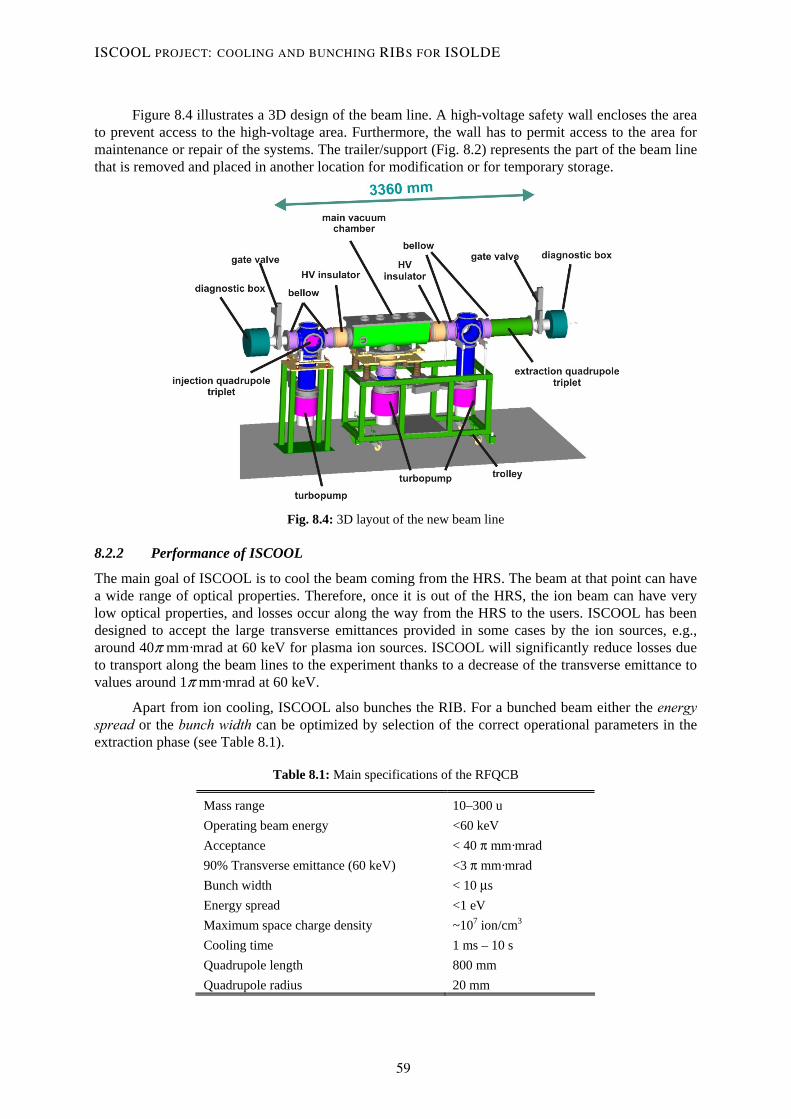
Figure 8.4 illustrates a 3D design of the beam line. A high-voltage safety wall encloses the area to prevent access to the high-voltage area. Furthermore, the wall has to permit access to the area for maintenance or repair of the systems. The trailer/support (Fig. 8.2) represents the part of the beam line that is removed and placed in another location for modification or for temporary storage.
Fig. 8.4: 3D layout of the new beam line
8.2.2 Performance of ISCOOL
The main goal of ISCOOL is to cool the beam coming from the HRS. The beam at that point can have a wide range of optical properties. Therefore, once it is out of the HRS, the ion beam can have very low optical properties, and losses occur along the way from the HRS to the users. ISCOOL has been designed to accept the large transverse emittances provided in some cases by the ion sources, e.g., around 40π mm·mrad at 60 keV for plasma ion sources. ISCOOL will significantly reduce losses due to transport along the beam lines to the experiment thanks to a decrease of the transverse emittance to values around 1π mm·mrad at 60 keV.
Apart from ion cooling, ISCOOL also bunches the RIB. For a bunched beam either the energy spread or the bunch width can be optimized by selection of the correct operational parameters in the extraction phase (see Table 8.1).
Table 8.1: Main specifications of the RFQCB
Mass range 10–300 u Operating beam energy <60 keV Acceptance < 40 π mm·mrad 90% Transverse emittance (60 keV) <3 π mm·mrad Bunch width < 10 μs Energy spread <1 eV Maximum space charge density ~107 ion/cm3 Cooling time 1 ms – 10 s Quadrupole length 800 mm Quadrupole radius 20 mm
ISCOOL PROJECT: COOLING AND BUNCHING RIBS FOR ISOLDE
59
8.2.3 Modifications of ISOLDE operation
8.2.3.1 New time structure of the HRS
The implementation of the RFQCB after the HRS will give ISOLDE a new time structure. The extraction optics of the RFQCB will become the new starting point for ISOLDE beam optics. The reason is that the optics of the beam released by ISCOOL, mainly the transverse emittance, does not depend on the type of beam entering the cooler. Moreover, the capacity of ISCOOL to convert the quasi-continuous ISOLDE beam [1] into a bunched beam links the timing of the system to that of the HRS front-end. The new timing at ISOLDE will look much as presented in Fig. 8.5.
Fig. 8.5: New time structure for ISOLDE HRS
ISOLDE HV corresponds to the signal sent to the high-voltage power supply of the HRS front-end platform. As explained in Ref. [1], the voltage drops just 35 μs before the impact from the Proton Synchrotron Booster (PSB) and returns to its initial value (normally 60 kV) 5 ms afterwards. Once the beam is produced at the ion source and accelerated to the corresponding energy, the RIB that is transported to the users can be selected by using the BEAM GATE signal. With the BEAM GATE it is possible to choose the best moment to capture the RIB and to kick-start the beam at any time. In Fig. 8.5, high values of the signal BEAM GATE indicate the time when the device is opened and the beam is transported. The BEAM GATE signal transforms the ISOLDE beam into a quasi-continuous beam with bunches of 100 ms width every 1.2 s.
The new capabilities provided by ISCOOL are based on signals sent to the axial electrodes whose main function is to trap, bunch, and extract the beam. The signal RFQ END PLATE corresponds to the potential of the last axial electrode of the trap and determines the time that the beam is collected in the trap. Once the potential of the last electrode is decreased, the bunch of ions accumulated is expelled and accelerated by the extraction optics up to the desired beam energy. The potential of the last axial electrode is decreased for a period which ensures that the bunch is completely released. At the same time, ions that have not been trapped are prevented from exiting the trap, thereby avoiding an increase of the time width of the bunch.
If the time spread of the bunch needs decreasing, one of the axial electrodes placed in the last part of the trap structure can be used to ‘kick out’ the beam (signal RFQ SEGMENT 21). The signal RFQ SEGMENT 21 shows the behaviour. When the potential of the end plate is switched off, the potential of one of the last segments can be increased, provoking a reduction of the time spread of the bunch but also an increase in the energy spread. This happens because the ions that are farthest from the exit hole, when the voltage of the end plate is switched down, will have more kinetic energy as a result of the increase in the potential of one of the last segments.
On the other hand, some changes in the present beam gates will have to be made. On account of constraints in the length of the beam line, the user’s beam gate placed in the ISOLDE beam line has to be removed. Hence only one beam will be left just before the HRS magnets.
IVAN PODADERA ALISEDA
60

8.2.3.2 Removal of the users beam gate
Nowadays, there are two beam gates at ISOLDE to stop the beam: one before the mass separators and controlled by the operators and another after the mass separators which can be controlled by the users. The beam section where ISCOOL will be installed (see Fig. 8.1) contains the users beam gate. The function of this device is that the user can block out whenever the RIB is released from the separator to the experiment. Because of the installation of ISCOOL and the length constraints, this device had to be removed. Nevertheless the users will still be able to control the beam in the same way as before, although the device controlled will be the beam gate before the mass separators (the only one remaining).
8.3 Technical design of ISCOOL
8.3.1 Optics system
The main goal of the ISCOOL project is to improve the optics of the ISOLDE beam line. The device is considered a new starting point for the optics of ISOLDE, so a lot of care has to be taken in the design of the optical parts. In the following section there is a general description of the deceleration (injection), cooling and bunching, and acceleration (extraction) parts.
8.3.1.1 Injection into the RFQCB
The injection of the ion beam into the RFQCB is a crucial point of the device. It is important to avoid losses caused by ions hitting the electrodes or too energetic ions colliding with the buffer gas. The ISOLDE beam is normally transported at 60 keV and because the injection energy into the quadrupole has to be around 100 eV, a deceleration system is required. The system chosen (Fig. 8.6) is one that uses two injection electrodes that, combined with the injection plate of the quadrupole cavity, ensure an efficient injection of all the ISOLDE beams. To test the geometry some simulations in SIMION were done by T. Eronen. The simulations showed that, using the following voltages: 54 kV for the first electrode and 55 kV for the second electrode, the beam could be fully injected into the RFQCB without losses. The voltage of the injection plate of the quadrupole cavity allows control of the injection energy of the ions into the RFQCB. Setting the injection plate voltage to 59.9 kV, the injection energy of the ions into the gas will be 100 eV (design value).
Fig. 8.6: Layout of the injection optics for ISCOOL
ISCOOL PROJECT: COOLING AND BUNCHING RIBS FOR ISOLDE
61

8.3.1.2 Beam cooling process
The reduction of the emittance due to the cooling process inside the RFQCB depends only on the temperature of the buffer gas and not on the kind of beam that is being cooled. Therefore, one can say that the beam is ‘losing its memory’ in the cooler and that the extraction of the beam from ISCOOL becomes the new starting point of the optics at ISOLDE-HRS.
Fig. 8.7: Transverse emittance for two ion beams in thermal equilibrium with the buffer gas. The right-hand figure shows a beam with longitudinal velocity component (from Ref. [9]).
Figure 8.7 shows the action diagram (x,vx) simulated with SIMION [10] for two ion beams in equilibrium with the buffer gas that is already cooled. The right-hand figure corresponds to a beam in equilibrium with the buffer gas but with a longitudinal velocity component due to an axial electric field applied along the axis of the quadrupole. The left-hand figure is for an ion beam without an axial electric field applied.
During the cooling process, it is important to confine the ions in the axis of the quadrupole while they are colliding with the buffer gas. The confinement is done by the RF quadrupole electric field created by the quadrupolar rods. The RF field applied to the rods is controlled by an RF amplifier which can vary the amplitude and the frequency of the RF electric field. The goal is to assure the pseudopotential well in the transverse plane and the stability of the transverse ion motion. This means fixing the Mathieu parameter q at around 0.5. The mathematical expression is expressed as:
RF2 2
0 RF
4QVqmr
=Ω
, (8.1)
where Q is the charge of the ion, RFV is the RF amplitude (0 to peak), m the mass of the ion, 0r the characteristic radius of the quadrupole defined as half of the distance between opposite rods, and RFΩ the RF angular frequency. For different types of RIBs, q will change according to variations in the mass of the ions. Therefore, modifications either in RFV or RFΩ have to be done in order to keep the ion beam motion stable inside the trap. As shown in Table 8.1, the range of operation masses for ISCOOL is from 10 u to 300 u. Table 8.2 shows the operational values for the RF amplifier.
IVAN PODADERA ALISEDA
62

Frequency f represents the frequency of RF field ( )RF 2 .fπΩ = D is the so-called pseudopotential well depth, expressed in [V] by:
RF
4qVD = . (8.2)
Table 8.2: Frequency and voltage amplitude of RF applied to the quadrupole for different ion mass values
m [amu]
f [MHz]
VRF (0-peak) [V]
q D [V]
10 0.80 130 0.50 16.13 20 0.60 147.5 0.50 18.46 50 0.42 180 0.50 22.44
100 0.30 185 0.50 23.23 120 0.28 192.5 0.50 24.07 140 0.26 192.5 0.50 23.92 160 0.24 190 0.50 23.93 180 0.22 180 0.50 22.72 200 0.21 180 0.50 22.44 220 0.21 200 0.50 25.19 240 0.20 195 0.50 24.20 250 0.20 200 0.49 24.44
Figure 8.8 shows the optimized frequency and amplitude of the RF that should be applied to the
quadrupole rods for different ion mass values. The optimization values are shown in Table 8.2.
0
50
100
150
200
250
0.00 0.20 0.40 0.60 0.80 1.00
f [MHz]
V RF
(0-p
eak)
[V]
1020
50100200
250
Fig. 8.8: Plot of the optimized frequency and voltage amplitude of RF for different ion masses
Figure 8.9 shows the stop cooling distance dependent on the buffer gas pressure and the entry energy of the ions inside the trap. Using this distance it is possible to calculate the length of the quadrupole.
ISCOOL PROJECT: COOLING AND BUNCHING RIBS FOR ISOLDE
63

Fig. 8.9: Cooling distance of ions inside the RFQCB (from Ref. [9]). E is the entry energy of the ions in the buffer gas, m the ion beam mass and M the buffer gas ion mass.
8.3.1.3 Bunching and extraction to the ISOLDE beam line
Once the beam has been cooled inside the RFQCB, it has to be bunched (when desired) and accelerated again to 60 keV to be transported to the experiments. As in the case of the injection system, the extraction is made of two electrodes, but their geometry is completely different from that of the injection electrodes, see Fig. 8.10.
Fig. 8.10: Layout of the extraction optics for ISCOOL
The beam extraction system was optimized using the SIMION code for different ions. An example of the extraction of a bunch of 100 cesium ions is shown in Fig. 8.11. The 90% transverse emittance at 60 keV is reduced in both phase spaces to about 1 π mm · mrad and the bunch width is only around 4 µs. More information about the simulation conditions can be found in Ref. [7].
IVAN PODADERA ALISEDA
64

Fig. 8.11: Simulations with SIMION of transverse phase spaces (top), beam size (bottom left) and time of flight (bottom right) of cesium ions. The ellipse encloses 90% of the ions.
The bunch process is done before the acceleration using the last axial electrodes of the structure. For an experiment that needs a small time spread (e.g., a collinear laser spectroscopy experiment) the bunch can be extracted using the push-and-pull procedure (see Fig. 8.12). It consists in simultaneously increasing the voltage of one of the last axial electrodes of the RFQCB and decreasing the voltage of the extraction plate. With this procedure, time spread is reduced but energy spread is increased. If the energy spread needs to be optimized, then a normal extraction procedure—lowering the extraction plate voltage—is used.
Fig. 8.12: Ion extraction procedures from an RFQCB: smooth extraction (left) and push–pull extraction (right)
8.3.2 Mechanical system
The main features of the mechanical design are
– Separation of the electrodes creating the axial electric field (axial electrodes) and the electrodes creating the quadrupole RF electric field (RF electrodes).
– Great flexibility to optimize the axial electric field in a first test phase and during normal operation.
ISCOOL PROJECT: COOLING AND BUNCHING RIBS FOR ISOLDE
65

– Easy to set up, modify, repair, and remove.
– Bake-out optimized.
Figure 8.13 shows the design of the inner structure of the RFQCB [11]. In the figure, half of the quadrupole is shown. The axial electrodes are separated by ceramic insulators. The right part of the figure is the injection side of the cooler. It can be seen that the first and last electrodes are more segmented since it is necessary to have better control of the field in these regions. The structure is made of stacked, variable-depth electrodes separated by electric isolators. The entire package is supported and stiffened by the quadrupole rods and enclosed by the injection and the extraction plates.
Fig. 8.13: Section of the mechanical structure of the RFQCB (left) and transverse cut of the assembly (right)
In Fig. 8.14 axial electrodes of different lengths are shown. Longer ones are placed in the centre of the quadrupole where the gradient of the potential is smaller. In the injection region(s) and above all in the extraction regions, shorter electrodes are used to enable very precise modification of the shape of the potential depending on the users’ requirements.
Fig. 8.14: Geometry and picture of the axial electrodes with different lengths
IVAN PODADERA ALISEDA
66

All the electrodes (axial and quadrupole rods) are made of stainless steel and electrically isolated by ceramic spacers made of alumina (Al2O3). Differential potentials of around 1 kV can be supplied. The electrical connections to the electrodes are made with very small plugs that can be connected and disconnected easily.
Two more electrodes in each side, the so-called injection and extraction electrodes are supported by an electrical insulator of the main vacuum chamber. The distances between these electrodes are fixed, but some metallic spacers can be added to vary the distance by a few millimetres. In addition, ground electrodes on the injection and extraction sides can be moved a few millimetres to optimize the optics.
ISCOOL is placed above a trailer that allows easy removal from the beam line. To make changes, the cover of the main chamber can be lifted by a crane, but a lot of care has to be taken to assure that all the injection and extraction electrodes have been removed beforehand.
8.3.3 Vacuum system
The RFQCB works continuously with a flow of buffer gas entering the quadrupole chamber. The pressure inside the chamber, around 0.1 mbar for helium, has to be down to 10–7 mbar at the ISOLDE beam line. The transition is made through a differential pumping system of three turbo molecular pumps (see Fig. 8.15). The first one pumps the main chamber, while the other two pump the injection and extraction parts, respectively. Differential pumping between the three sections is achieved by the use of small holes for the injection and extraction plates of the quadrupole cavity. In the first step, the pressure is decreased from the pressure in the quadrupole cavity, around 0.1 mbar, to the pressure in the main chamber, around 10–3 mbar. The second step is by the holes of the last injection electrode and the first extraction electrode. The pressure is decreased from 10–2 mbar, up to around 10–5 mbar either in the extraction or injection regions. Finally, the last step to obtain the 10–7 mbar standard at the ISOLDE beam line is carried out by the ground injection and extraction electrodes. The turbo molecular pumps used are: a 1650 l/s in the main chamber (TP1), and two 1100 l/s, one for the injection (TP2) and one for the extraction side (TP3). When the RFQCB is removed from the beam line and just a straight beam line is placed, only the injection pump remains in place. The whole beam line is closed by two main valves on both sides making a new vacuum section.
Fig. 8.15: Schematic layout of the vacuum system of the RFQCB (only the main components are represented)
ISCOOL PROJECT: COOLING AND BUNCHING RIBS FOR ISOLDE
67

8.3.3.1 Buffer gas
To cool the ion beam, the inner chamber is filled with a buffer gas. The gas chosen must have a high chemical stability and a very low mass (only beams with ions of mass higher than the buffer gas mass can be cooled). Helium fulfils both requirements and looks the best choice. To minimize the losses due to impurities inside the trap [3], helium of maximum purity will be used with a percentage of helium 99.9999% (He grade 6.0). Furthermore, a purification system will be added to decrease the impurities to a level below 10 ppb. The gas flow will be regulated to control the gas pressure inside the chamber. The gas bottle will be placed on a high-voltage platform to avoid problems with gas flow along high-voltage insulators. The gas will enter the main chamber through one of the flanges of the top cover using a gas feedthrough and is electrically insulated before entering the RFQCB chamber.
The gas throughput of ISCOOL was estimated to be around 2–3 mbar·l/s as a function of the diameter of the holes at the injection and extraction plates. The operation time of ISCOOL can be calculated either in a more conservative (and probably realistic) way with the complete running period of ISOLDE (around 30 weeks), or only with the running period of the HRS that is half of the total time (15 weeks). Therefore, the estimated running time of ISCOOL varies from 210 days to 105 days of operation per year. For big bottles of helium (50 l and 200 bar), the duration of the gas will vary from 40 days (6 weeks) for a big throughput (3 mbar·l/s) to 65 days (10 weeks) for a low throughput (2 mbar·l/s).
8.3.4 Electronics system
ISCOOL is a high-voltage device that has to operate at the same voltage as the HRS front-end. The electronics providing the high voltage are placed at ground level in a separate rack. This gives the HV to ISCOOL and to an isolated platform supporting the rack with all the DC and RF electronics for ISCOOL and the gas bottle. The 220 V for the electronics at the HV platform are supplied through an isolation transformer of the same type as used in the ISOLDE front-ends to ensure replacement in case of problems.
8.3.4.1 DC electronics
Thanks to the use of the axial electrodes, the electronics to apply the voltage to the electrodes of the RFQCB can be separated: the axial electrodes receive the DC component and the quadrupole rods the RF component. The DC component has to be applied to all the axial electrodes. The number of electrodes can be varied but the starting point is 25. Voltage to the electrodes is supplied by standard ISOLDE DC power supplies modified for 1 kV (DC24-D3500) with an accuracy higher than 0.1%. The last axial electrodes require a fast variation of the voltage to release the bunch inside the trap. To assure a good stabilization of the voltage in such a short period (~10–8 s) [2], the voltage for the electrodes is provided by two different power supplies and a fast switch controlling which power supply provides the voltage to the electrode. In addition, the voltage of the two injection electrodes (with voltages around 50–60 kV) are provided by two standard power supplies. The voltage of the first one is provided by a FUG HCN 7E-20000 NEG (20 kV), and the second one by a FUG HCN 7E-12500 NEG (12.5 kV). In the extraction process two other power supplies are used for the extraction electrodes. One ISOLDE standard DC24-D3500 modified for 1 kV, and another FUG HCN 7E-20000 NEG, for the second extraction electrode. In all the cases the voltages applied are negative as the power supplies are placed in a high-voltage platform at 60 kV.
8.3.4.2 RF amplifier
An RF electric field must be applied to the quadrupole rods in order to obtain the alternative quadrupole field that confines the beam. Here the magnitudes (frequency and amplitude) of the electric field are very low and no commercial amplifiers for that purpose are available on the market. The magnitudes required for the ISCOOL RF amplifier can be observed in Table 8.2. In Table 8.3 the
IVAN PODADERA ALISEDA
68

frequency and amplitude ranges coming from the magnitudes required are specified. A push–pull oscillator has been developed by Klaus Rudolph and supplies the RF field to the electrodes. The system allows the independent setting of the amplitude and frequency of the RF.
Table 8.3: Magnitudes of the RF amplifier for ISCOOL
Frequency range 100 kHz – 1.5 MHz
Amplitude range (0-to-peak) 100–250 V
8.3.4.3 High voltage
The whole of RFQCB works on a high-voltage platform that has to be linked to the extraction voltage of the HRS front-end. Usually the energy of the RIBs at ISOLDE is 60 keV but the voltage can vary depending on different front-end conditions, e.g., vacuum problems can limit the operation voltage to lower voltages. The high voltage is supplied by a power supply FUG HCN 140–6500. Two situations can switch off the high-voltage power supply automatically. A problem in the vacuum system (e.g., pressure too high in the beam line or breakdown of some of the pumps) would open a microswitch. An entry into the ground cage or the electronics cage would open the corresponding microswitch.
8.3.5 Integration in the ISOLDE control system
ISCOOL is fully integrated into the ISOLDE control system, which means it can be controlled and optimized from the ISOLDE control room. The parameters that serve to optimize the optics and the cooling and bunching processes can be varied on-line. Moreover, the vacuum system is integrated as another vacuum section of ISOLDE. To sum up, the main points to be controlled on-line and modified are
– Control of the HV (scaling all the voltages automatically in consequence).
– Control of the parameters of ISCOOL. In two different ways: a first one visible to the user, where, by modifying the mass required and the bunch extraction parameters, the beam is automatically extracted; another way that allows a change to more low-level parameters such as the frequency and the amplitude of the RF field, or the voltages of all the electrodes creating the DC field.
An easy and rapid integration of ISCOOL into the ISOLDE control system is assured thanks to the use of standard components (PLCs), most already being used at ISOLDE. A more complete description of the present ISOLDE control system can be found in Ref. [12].
8.4 Polarized beams from a gas-filled RFQ trap
Establishing a nuclear polarization or alignment with laser light can be simple and is a well-understood process. When a laser of know polarization is tuned to an atomic transition frequency, the atom is resonantly excited and absorbs the polarized angular momentum carried by the laser photon. The hyperfine interaction allows the absorbed angular momentum to be shared between the nuclear and atomic spins. After the atom decays, there is a net increase in the nuclear polarization. If the decay returns the atom to its original level, the cycle be repeated and, for certain optical pumping schemes, nuclear polarizations close to 100% can be achieved.
Polarized ions can be produced in this way inside an ion source but the polarization is difficult to preserve because of the nuclear or atomic spin precessions that occur in the magnetic fields of the mass separator. It is far better to induce the polarization after mass-separation since there are only electrostatic elements in the subsequent delivery line. This is exactly how the beta-NMR experiments on COLLAPS have worked for selected systems, applying optical pumping in the collinear-beam geometry.
ISCOOL PROJECT: COOLING AND BUNCHING RIBS FOR ISOLDE
69

A more general approach is offered by the new ISCOOL. The ions may be trapped for some hundreds of milliseconds in a small volume near the trap exit, diffusing in the low-pressure helium buffer gas. This is an ideal environment for producing laser-induced nuclear polarizations. Nuclear spin relaxation rates of some atomic species in noble gases are extremely slow—hours rather than seconds. A laser beam, aligned along the axis of the cooler can illuminate the entire ensemble of trapped ions with an interaction time that is three or four orders of magnitude longer than is possible in the collinear-beam geometry. High polarizations could be achieved with modest laser powers.
There are a limited number of elements that could be laser-polarized using a single laser colour on a transition from the ionic ground state. The optimum scheme for a particular element may require pumping on a transition from a metastable state. In such cases, several laser frequencies would be required. Overlapping such beams in the trapping region is straightforward.
Initial studies of optical pumping in an ion cooler have been carried out at the IGISOL facility, Jyväskylä [13]. In this case the laser light was provided by pulsed titanium-sapphire lasers with frequency-doubling. The interest here was to transfer the ion population to particular metastable states required for an experiment downstream of the cooler. In these cases the large pumping effects saturated at modest laser powers (30 mW). Continuous-wave lasers would be equally effective. ISOLDE offers a broad range of lasers suitable for this application, whether it is the high-repetition-rate RILIS lasers or CW lasers owned by experimental groups.
8.5 Status of the project
At present, the complete ISCOOL assembly is being tested in a dedicated setup [14] constructed in the off-line laboratory, see Fig. 8.16. The mechanical components were assembled and aligned without problems, see Fig. 8.17. The electronics and control systems have been successfully integrated. First tests of the vacuum, high-voltage and low-voltage supplies are positive and tests with a surface-ion source are in progress.
Fig. 8.16: Picture of the test bench of ISCOOL at the ISOLDE off-line laboratory
IVAN PODADERA ALISEDA
70

Fig. 8.17: Picture of the ISCOOL assembly
9 Acknowledgements I would like to acknowledge my supervisors, Ari Jokinen and Mats Lindroos for all the support they have given me in all parts of the project. I also thank the ISOLDE target, technical and physics group for the nice work environment and all the support given during the development of the project. In particular, I would like to mention Jacques Pier-Amory and Nicolas Chritin who have made the mechanical design possible. I would like to thank Ludwig Maximilans University, Munich for support in the mechanical area and for the electronics manufacturing. In addition, I would like to thank CSNSM, particularly Dave Lunney and Jean-François Kepinski, for help in the construction of the test bench and manufacture of ISCOOL. I also acknowledge the support of the University of Mainz in the manufacturing phase. The project would not have been feasible without the manpower and grant support from the Department of Nuclear Physics of the University of Manchester, their support was essential. Finally, I would like to thank Pierre Delahaye, Ermanno Barbero, Tuomas Tallinen and Ernesto Mané for finishing the assembly and the off-line setup.
References [1] E. Kugler, The ISOLDE facility, Hyperfine Interact. 129 (2000) 23–42. [2] D. Rodriguez, An RFQ for accumulation and cooling of heavy radionuclides at SHIPTRAP and
high precision mass measurements on unstable Kr isotopes at ISOLTRAP, PhD Thesis, Universidad de Valencia, Spain (2003).
[3] A. Nieminen, Manipulation of low-energy radioactive ion beams with an RFQ cooler; application to collinear laser spectroscopy, PhD Thesis, University of Jyväskylä, Finland (2002).
[4] F. Herfurth, A new ion beam cooler and buncher for ISOLTRAP and mass measurements of radioactive argon isotopes, PhD Thesis, Rupertus Carola University of Heidelberg, Germany (2001).
[5] J. Billowes, Laser spectroscopy of radioisotopes and isomers, Nucl. Phys. A 682 (2001) 206c–213c.
[6] A. Jokinen et al., RFQ-cooler for low-energy radioactive ions at ISOLDE, Nucl. Instrum. Methods B 204 (2003) 86–89.
ISCOOL PROJECT: COOLING AND BUNCHING RIBS FOR ISOLDE
71

[7] I. Podadera Aliseda, New developments on preparation of cooled and bunched Radioactive Ion Beams at ISOL facilities: the ISCOOL project and the rotating wall cooling, PhD Thesis, Universitat Politècnica de Catalunya, Spain (2006).
[8] I. Podadera, RFQ cooler and buncher (and beam line associated), CERN-AB-NOTE-2004-062, Geneva, Switzerland.
[9] M. Petersson, A Monte Carlo method for the simulation of buffer gas cooling inside a radio frequency quadrupole, Masters Thesis, Linköping University, IFM (2002).
[10] D.A. Dahl, SIMION for the personal computer in reflection, Int. J. Mass Spectrom. 200 (2000) 3.
[11] I. Podadera et al., Design of a second generation RFQ Ion cooler and buncher (RFQCB) for ISOLDE, Nucl. Phys. A 746 (2004) 647–650.
[12] O. C. Jonsson, F. Locci, G. Mornacchi, ISOLDE Front-end study, CERN-I2k-Note-11(Spec.). [13] A. Nieminen et al., On-line ion cooling and bunching for collinear laser spectroscopy, Phys.
Rev. Lett. 88 (2002) 094801. [14] I. Podadera et al., Preparation of cooled and bunched beams at ISOLDE, Eur. Phys. J. A 25
Suppl. 1 (2005) 743–744.
IVAN PODADERA ALISEDA
72

9 REX-ISOLDE low-energy stage Fredrik Wenander
9.1 Introduction
The REX-ISOLDE low-energy stage prepares the radioactive ions produced at ISOLDE for acceleration in a compact LINAC to energies up to 3 MeV per nucleon [1]. It consists of a Penning trap (REXTRAP), a charge breeder (REXEBIS), and an achromatic A/q separator of the Nier spectrometer type. The charge breeding efficiency depends critically on the quality of the injected beam, i.e., its longitudinal and radial emittances. The purpose of the trap is to collect and cool the radioactive ions delivered by ISOLDE before they are sent in bunches into the EBIS. Within the trapping area the ion motions are damped by the combined effect of collisions with a buffer gas (He, Ne or Ar) and a transverse RF excitation at the ion cyclotron frequency. In the EBIS, the ions are charge-bred into charge states fulfilling the requirements of the subsequent injection into the LINAC, i.e., 3 ≤ A/q ≤ 4.5. Thereafter the mass separator selects the charge state of interest. The typical cycle time is made up of 20 ms trapping followed by 20 ms charge breeding. For ions heavier than mass 40 longer breeding times can be needed. Until now, the longest breeding time with radioactive ions was 198 ms for 142Xe. Routinely, an overall efficiency for the REX-ISOLDE low-energy stage between some per cent and 10% is obtained. A detailed description of the beam preparation can be found in the CERN Report describing the REX-ISOLDE facility [2].
9.2 Motivation for breeder upgrade
Several factors can limit the efficiency of the beam preparation, for instance high beam intensities and breeding of heavy elements. These are also the two main reasons for an upgrade of the low-energy stage as described below.
9.2.1 Charge breeding of heavier ions with maintained short breeding time
With an upgrade of the LINAC energy the Coulomb barrier can be reached, and transfer reactions carried out, for heavier elements. Because of the unfavourable Z/A ratio and the higher number of shells that has to be depleted from electrons for heavier elements, the charge-breeding time becomes longer. The present breeder is designed for A < 50. To reach the required A/q for A > 100, breeding times longer than 100 ms are required. Long breeding times have several negative aspects, for example:
– Decay losses inside trap and EBIS, particularly for short-lived elements.
– Dead-time losses in the experimental detectors when the breeding repetition rate is low.
– Space charge saturation in the Penning trap as the trap has to collect 1+ charged ions during the long breeding time.
The way to maintain a short breeding time is to increase the electron beam current density inside the EBIS. As the attained charge state is proportional to the breeding time multiplied by the electron current density, we conclude that the electron beam density has to be increased from a present measured value of ~100 A/cm2 to at least 500 A/cm2, a value that is feasible in an EBIS. In addition, losses occur in the breeder for heavier elements since the electron beam potential of the modest electron beam current in the REXEBIS is not sufficient to keep the highly charged ions confined when they become heated by electron–ion collision. To counteract this, an increased electron beam current is required.
73

9.2.2 Increased radioactive beam intensities
With HIE-ISOLDE the proton intensity on the primary target will be increased as well as the radioactive yield production. Then, for high yield isotopes the space charge limitation inside the Penning trap (and eventually the EBIS) may become a limitation. The present Penning trap–EBIS arrangement is limited to approximately 1.3·108 ions/pulse by the space charge limitation in the Penning trap; at 50 Hz that corresponds to 1 nA. However, even at some ten pA from ISOLDE, space charge effects can prevent a proper cooling of the ion cloud inside REXTRAP. The injection efficiency into the EBIS then suffers from a lower beam quality. If the current is even larger (>100 pA), the space charge can also inhibit the trapping fields and losses might occur in the trap. In conclusion, an increased space charge capacity of the low energy stage is called for.
9.2.3 Upgrading the existing REXEBIS
The quickest and most cost effective approach would be to upgrade the electron beam of the existing REXEBIS. In fact, there is already an ongoing programme investigating the possibilities (see further down), but even if fully successful it would only partly resolve the issues mentioned above. For instance, the relatively low solenoidal magnetic field (2 T instead of 5–6 T for high performing EBIS devices) makes the launching and compression of a high-current electron beam difficult due to the Brillouin limit. Secondly, the REXTRAP would still be necessary for bunching and cooling of the ISOLDE beam, thus still limiting high-current beams. Finally, the inherent fragility and lack of modularity of the REXEBIS would remain.
9.3 RHIC EBIS or PHOENIX ECRIS
It is important to stress that the buncher–breeder part in the REX-ISOLDE post-accelerator scheme should not become ‘an experiment in the experiment’. It can lead to long set-up times and low reliability, which reduces the useful beam time to the users, and in addition calls for extensive manpower for the operation. We therefore advocate relatively straightforward, and well-proven, machine concepts and avoid a number of suggestions as to how, for example, the efficiency and the charge state distribution of the breeder can be improved by special and ion-beam case-specific manipulations. Which of the two solutions presented below will be preferred will be decided upon after the evaluation period.
9.3.1 RHIC EBIS solution
An attractive solution would be to replace the REXEBIS with a charge breeder similar to the RHIC EBIS [3]. This has a high electron beam current density and very high current so both the charge state/breeding time and intensity problems could be addressed. It could be installed at the same position as the REXEBIS and connect to the beam transfer line from the trap and to the mass separator. Thus, the modifications of the existing systems would be minimal. The idea would be to copy the RHIC EBIS to a very large extent and benefit from the thorough R&D that has gone into this device. Most of the performances of the RHIC EBIS have already been proven with the TestEBIS [4], see Fig. 9.1, which is a shorter version and serves as a test stand.
The TestEBIS runs with an electron beam current of 10 A, to be compared with a normal operation current of 200–300 mA for the REXEBIS. The electron energy is 20 keV, which is sufficient for ionizing all elements to A/q < 4. With a trap length of 0.7 m, more than 1.5·109 Au32+ ions have been extracted from one pulse. The current density in full field is > 500 A/cm2, which produces Au32+ ions within 35 ms (experimental value). To breed the extreme case of uranium to 55+ takes 200 ms, while Xe31+ is reached in only 50 ms (theoretical values). The RHIC EBIS, which is going to have double the trap length and electron beam current, will have an even more impressive breeding performance.
FREDRIK WENANDER
74

Fig. 9.1: The RHIC TestEBIS setup at BNL
To make full use of the large breeding capacity of a RHIC-type EBIS the current-limiting Penning trap has to be bypassed. With the bunching and trapping switched off and the trap on ground potential, and in the absence of buffer gas but with magnetic field present, it should be possible to transport close to 100% of the beam through the REXTRAP1. The necessary improvement of the transverse phase space could be carried out in the RFQ cooler [5] to be installed after the HRS magnets. The cooler can work in continuous mode and should be capable of handling 10 nA beams. The injection into the EBIS then has to be continuous, which could lead to a reduced efficiency. Nevertheless, an efficiency of 4% in one charge state for continuous injection has already been shown in the REXEBIS, and with the large current and current density in a RHIC EBIS higher values should be attainable. For lower beam intensities (<100 pA) the Penning trap and RHIC EBIS are used in series with bunched operation as at present.
The striking features of the RHIC EBIS as charge breeder are its fast breeding and large space-charge capacity. In addition, it is modular with the gun, trapping and collector regions vacuum-separated. Electron gun interventions can therefore be carried out separately and this should increase the reliability and up-time. A different, larger cathode than for the REXEBIS is used with longer lifetime. The larger electron beam current should also lead to an enlarged ion-injection acceptance.
A few remarks and questions have to be posed. For example, the higher ion beam acceptance of the device also means that the ion beam emittance will be larger than for the REXEBIS, typically 30 π·mm·mrad at 20 kV. This emittance can be accepted by the RFQ cavity, but one still has to verify the transmission through the separator with beam simulations. Moreover, the energy spread of the extracted beam is large, around 1.5 keV · q for self-extraction (~50 µs), so a slow extraction (ms) might have to be used in order to control the energy spread. The high electron beam current could also lead to higher residual gas peaks unless the vacuum is kept under control. Finally, the continuous injection mode should be further experimentally verified for this system, as it inherently has a lower efficiency than for the pulsed injection. In connection with this, the efficiency, emittance and current limitation of the RFQ cooler should be verified.
1 In fact, 75% transmission was obtained with the trap at a voltage similar to that of the ion source.
REX-ISOLDE LOW-ENERGY STAGE
75

9.3.2 ECRIS as charge breeder injector for the REX LINAC
At ISOLDE, there exists a second charge breeding device, the PHOENIX ECRIS charge booster [6]. The ECRIS works at 14 GHz radiofrequency, with permanent magnets and normal coils, and is designed to allow ion injection. Currently it is installed in the experimental hall at the GHM beam line, Fig. 9.2.
Fig. 9.2: Phoenix ECRIS ion source installed at the GHM beam line at ISOLDE
The main advantage of an ECRIS charge breeder is its large space-charge capacity and its operation without a preparatory buncher/cooler, which would allow for a high current throughput. In continuous wave mode the ECRIS can support injected beams of several μA. In pulsed mode 2 × 10¹² charges per pulse have been demonstrated. Its ability to operate in continuous wave mode would also make full use of a superconducting LINAC and reduce the event pile-up in the experimental detectors associated with pulsed beams. Finally, its operation is simpler than for the combined trap–EBIS system.
The PHOENIX ECRIS, currently being evaluated as charge breeder at a dedicated setup in the ISOLDE hall, could be installed at the side of the REXTRAP/REXEBIS system for injection in parallel into the REX LINAC. For low ion intensities and high purity beam requests, the EBIS would be used, while for high intensities the ECRIS would feed the LINAC. The ECRIS should be installed at the present position of the solid-state experiment ASPIC and be connected to the REX LINAC via a magnetic and electrostatic spectrometer (already available, but not installed) similar to the REX mass separator. Using such a separator, mass and energy selections can be performed and the high residual-gas contamination be suppressed to a large extent. A movable bender directs the beam into the REX beam line. The emittance of the extracted beam from the ECRIS is smaller than the acceptance of the RFQ. Using afterglow, an extraction time of ~5 ms can be achieved. With a confinement time of 70–200 ms, the duty cycle for the LINAC falls within the present specifications (<10%). However, with a mass-to-charge ratio between 4 and 8 after breeding, the REX LINAC needs to be modified as it is designed for A/q < 4.5. The proposal would be to introduce a stripper foil for the heavier masses (typically A > 80) at the 1.2 MeV/u energy, that is after the IH structure, with a 10–20% transmission for the selected charge state.
FREDRIK WENANDER
76

The high A/q inside the RFQ and IH structure calls for modification of these accelerating structures. Exchange of the drift tube structures and increased cooling due to a higher acceleration voltage and higher RF power are required. A design similar to the injector for UNILAC at GSI could be used, limiting the effort to production of the structures. The RF frequency can be maintained, but the RFQ, buncher, and IH amplifiers have to be upgraded for the higher power level. Also the lenses of the matching section and the inner tank triplet inside the IH structure have to be upgraded as they are not specified for such a high A/q value. After the IH structure a box containing a stripper foil unit has to be added. As such an upgrade may entail a shift in axial position of certain LINAC elements as the stripper box is added for example, the upgrade should occur at the same time as the major upgrade of the LINAC.
Apart from the moderate A/q produced in an ECRIS, a number of other issues remain to be clarified. For instance, until now the recorded breeding efficiency for afterglow operation is only a couple of per cent. The breeder also exhibits difficulties in breeding elements lighter than A = 40. The large extracted stable beam originating from the residual gases amounts to several nanoamperes over the complete mass spectrum and often swamps the radioactive peaks. Finally, the confinement time for the ions in the plasma can in many cases exceed 100 ms which can lead to decay losses for short-lived ions. Several of these issues are under investigation in the programme Advanced charge breeding of radioactive isotopes within EURONS [7] and in Beam Preparation within EURISOL [8].
9.4 Development projects on the existing setup
Apart from the two upgrade scenarios suggested above, several less resource intensive development projects are being pursued on the present setup. Some have already started. The different R&D projects can be grouped into three categories: efficiency improvements of the different elements; electron gun development; and beam purity and beam optics enhancements. In addition, we are examining alternative uses for the ECRIS charge breeder. A summary of the status and needs of the different projects follows.
9.4.1 Improving the overall efficiency of REX-ISOLDE
9.4.1.1 Improving the trap efficiency
During the design study of REXTRAP, simulations of the ion injection, trapping and cooling processes were undertaken. A trapping efficiency close to 100% was expected. Experimentally 50–60% has been obtained for beams of intensity smaller than 10 pA, even less for higher intensities. Two possible reasons for the limited efficiency have been pointed out. Firstly, the magnetic mirror effect makes the injection from ISOLDE quite difficult, and on the injection side the ions may already be reflected before they enter the trapping region. Secondly, the ion-cooling method may not be strong enough to compress the ion cloud so it can exit the trap through the last collimator without a fraction being lost. A careful re-analysis of the beam injection conditions and a modification of the internal structure could improve the situation. By varying the beam focus and the diameter of the entrance and exit diaphragms, the losses could perhaps be reduced.
9.4.1.2 Narrowing the charge state distribution in the EBIS
Within the EURONS and EURISOL studies, two different means of narrowing the charge state distribution in the EBIS, and thereby increasing the number of particles in the peak charge state, will be investigated. Currently, a maximum of 25–30% can be obtained in the peak charge state. The first makes use of the large gap in ionization energy at the shell closure of atomic ions. By adjusting the electron beam energy accurately just below the ionization potential of a shell closure electron, a large fraction of the ions can end up in a single charge state. This is a specific case, and a suitable A/q value cannot always be found. The second method utilizes the dielectronic recombination resonance. The
REX-ISOLDE LOW-ENERGY STAGE
77

electron beam energy is adjusted to energies which enhance the dielectronic resonance cross-section for the dedicated ion species. In this way the recombination rate counteracts the ionization rate and stops the ionization at a certain charge state. This latter should be first tested at Heidelberg MPI-K before being possibly implemented at REX-ISOLDE. Both methods require an electron beam with an adjustable and in many cases low energy, which makes it cumbersome for the REX-ISOLDE, as the space-charge capacity will be low due to the perveance limit.
9.4.2 Electron gun development
The performance of an EBIS charge breeding system relies mainly on its electron optical system and thus on the electron source used. With two different approaches, the post anode gun and the high compression gun, the electron beam performance issue is addressed [9].
9.4.2.1 Post anode gun
The post anode gun, which should improve the beam quality and reduce the losses of electrons on electrodes, is a modification of the present gun. If successful it will yield a ~5 keV 0.5 A ripple-free beam. The beam scalloping present in the actual gun might be responsible for the beam losses limiting the operation to below 350 mA. Additionally, the beam radius minima might act as local ion traps, which reduce the ion extraction efficiency. A common way to reduce this ripple without major changes in other beam parameters is resonance focusing using a post anode at a high positive voltage. This has been implemented mechanically, but the commissioning and the optimization remain.
9.4.2.2 New high-compression gun
The design of a completely new gun making use of electrostatic and magnetic compression has begun. The gun should reach a current density of 400 A/cm2, more than three times the current density in the present system, and has a density compression of 300. To reach this value it is no longer possible to make use only of the magnetic compression with the present 2 T solenoid because of the Brillouin limitation. That means additional electrostatic compression is required. With a larger emitting surface and lower emission current density the cathode heating can be kept low, leading to an increased lifetime. Another goal is to store and charge-breed more ions in one cycle. For this reason the converging gun was designed to deliver a higher electron current of 1 A. This increases the trap capability by at least a factor 1.6 even at the higher beam energy of 10 keV. A beam simulation of a preliminary design is presented in Fig. 9.3. It turns out to be mechanically difficult to shape the magnetic field so it fulfils proper launching conditions for the electron beam from the gun, so further investigations are needed. The success of the project is uncertain.
Fig. 9.3: Beam simulation of a preliminary design for the high-compression gun
FREDRIK WENANDER
78

9.4.3 Beam purity and higher beam quality
The purity of the accelerated beam is often a critical issue. After the beam preparation at the trap and EBIS, two types of contaminants may be present. The first one is isobaric isotopes coming from ISOLDE, not separated out in the ISOLDE mass separator. The second one is the multicharged ions of similar A/q ratio originating from the residual gas inside the EBIS. The resolving power of the separator, (A/q)/Δ(A/q) ≈ 150, usually gives the possibility of choosing a charge state of interest not superimposed on a residual gas peak in the mass spectrum and thus a pure beam is delivered to the experiment. Nevertheless, in some cases a completely contamination-free beam is not attainable, particularly on a sub 0.1 pA level. In worst cases the beam is composed mainly of unwanted species.
9.4.3.1 Suppressing the isobaric contaminants from ISOLDE
From its intrinsic features the trap can be used as a high resolving mass separator. For example, the ISOLTRAP experiment has demonstrated that a resolving power of about 105 could be achieved in the preparatory trap. In 2005 we started a project to evaluate whether a similar resolving power can be attained in the REXTRAP and thereby the isobaric contaminations from ISOLDE could be reduced. However, certain limitations inherent to this separation method need to be studied in detail. Apart from possible space-charge effects, the required time of the RF excitation used for the separation is proportional to the resolving power. This becomes a limitation for short-lived nuclides. Secondly, a high resolving power requires a low buffer gas pressure. This may be a limitation for the trap efficiency. A modification of the internal trap structure and an improvement of the differential pumping scheme are most likely required. Preliminary results reveal that a mass resolution of 104 is attainable, see Fig. 9.4.
Fig. 9.4: A cyclotron resonance curve with a mass resolution of ~10 000 for 39K+ ions at low buffer gas pressure and RF excitation amplitude
9.4.3.2 Molecular beams
To suppress known contaminations from the ISOLDE target-ion source unit, it is in certain cases possible to inject into REXTRAP molecules rather than atomic ions. According to their chemical properties, the radioactive elements produced by the proton bombardment can combine with different impurities present in the target-ion source system to a molecule. The radioactive ion of interest is then moved away in the mass spectrum from the contamination. This method, the so-called molecular sideband extraction, has recently been used with 70SeCO+ molecules for the Coulomb excitation of Se nuclides with REX-ISOLDE [10]. In this way it was possible to suppress the contamination of 70Ge+ ions.
REX-ISOLDE LOW-ENERGY STAGE
79

Within REXTRAP, according to the voltages applied on the electrodes, the molecules could either be dissociated or kept intact. Figure 9.5 shows different time-of-flight spectra corresponding to these two schemes. If the molecule is kept intact inside the trap, the breaking occurs inside the EBIS. Systematic testing and efficiency measurements are needed to verify this method for different molecules, as the optimum trap settings are dependent on the electronegativity of the ion, for example. The optimization of this method would benefit from radioactive beam identification after the trap (see below).
Fig. 9.5: Time-of-flight spectra of the beam ejected from the trap after injection and cooling of SeCO+ molecules
9.4.3.3 Improvement of the vacuum system
The beam purity at the experimental station after acceleration through REX-ISOLDE is in most cases of utmost importance. An uncontrolled stable beam contamination distorts the results from Coulomb excitation and neutron transfer. Therefore, the suppression of residual gas contamination in the EBIS beam is important, and can be increased by coating the interior of the drift tubes and the electron collector with non-evaporable getter material. The major source of the stable impurities (C, N, and O) is the poor vacuum in the mass separator which has to be addressed. An improved vacuum in this section also reduces the electron recombination; this means the transmission efficiency for heavy, highly charged ions is increased. Further improvements involve a complete isolation of the roughing vacuum system for the trap from the rest of the low-energy stage beam lines, as it has been observed that the buffer gas of the trap can be transmitted to the EBIS backwards via the roughing pumping circuit.
9.4.4 Cooling techniques in charge breeders
Different ion–ion cooling methods are to be studied in the EURONS and EURISOL frameworks. They aim to improve the transverse emittance of the extracted beam from the different charge breeders. In the simplest form some cooling can be achieved by introducing a cooling gas into the EBIS. A more advanced scheme entails injection of the radioactive ions into a trapping region already partially filled with pre-injected buffer ions and different injection–trapping–extraction schemes [11]. Although the implementation of such techniques is not straightforward, with the current REXEBIS setup it is a
FREDRIK WENANDER
80

future open possibility. A new electrode structure would have to be designed, and a 1+ injection source and line added.
9.4.5 Comparison between Penning trap and RFQ cooler
An RFQ cooler buncher with high capacity will be in use at ISOLDE in the near future. Its beam cooling performance should then be compared to that of the Penning trap REXTRAP. The space-charge limitation, the time needed for beam cooling, and the emittance reduction are of primary interest.
9.4.6 Tape station for beam identification
Apart from suppression of unwanted beam contaminations, the identification of the charge bred beam is of utmost importance. Different beam diagnostics tools such as Faraday cups, beam profile and time-of-flight devices are installed at the trap and EBIS. After REXTRAP it is already possible to measure time-of-flight spectra of the cold extracted beam on a multichannel plate, and the beam composition can be determined to a certain extent. However, the present beam diagnostics system does not allow for a distinction between stable and radioactive beams. The identification can only be performed after acceleration at the experimental station. Thus, it would be beneficial to install a tape station with a complete detection system after the REX mass separator. In this way, the beam composition can be established before being injected into the LINAC and the functioning of the low-energy part can be assured. An electrostatic bender arrangement installed after the mass slit and before the RFQ quadrupoles would be necessary to deflect the beam 90° from the beam line onto the tape station.
9.5 Charge breeding ECRIS for beam purification and ion energy boosting
In case the charge breeding ECRIS is not used as an alternative breeder for the REX-ISOLDE LINAC, it could be used for boosting the ion beam energy for solid-state and nuclear astrophysics experiments. The ECRIS can also be used for improvement of the purity of beams. The charge states will develop differently for different elements. By injecting a radioactive mixture of originally the same A/q ratio into the ECRIS, it is then possible to minimize the A/q ratios overlap of the different elements. A subsequent separation of the charge-bred beam significantly improves the beam purity. This has already been proved with neutron-rich argon beams separated from a radioactive krypton contamination [12].
For many applications, particularly in solid-state or nuclear astrophysics, the beams available directly from the ISOLDE separators are too low in energy and the beams from REX-ISOLDE too high. The lowest beam energy from REX is 300 keV/u and the ISOLDE beam energy is between 20 and 60 keV for 1+ ions. A way to reach the intermediate energy could be to connect the charge breeding ECRIS to a high-voltage platform [13]. With a high-voltage platform, operating at a voltage around –300 kV, installed after the ECRIS, total ion energies of 360 · q keV are reachable. The high space charge capability of the ECRIS makes this particularly suitable for high-intensity, solid-state implantations. The PHOENIX is mainly efficient for slightly heavier elements, that is A > 25, and the reachable A/q limits the energy to ~50 keV/u. The existing HV platform could be moved to a position after the GHM and ECRIS, and be located 3 m above the floor to allow for an energy analyser after the separator magnet. This option presents very few complications, as space at the necessary position is available with little relocation effort. Apart from the general work on the ECRIS already mentioned, a beam line with focusing possibilities to the platform has to be produced.
Whether the DARESBURY/ISOLDE’s PHOENIX ECRIS is used for REX injection or HV platform feeding, a few common upgrades are needed. For instance, the vacuum has to be consolidated and standardized, and the control system upgraded. The magnetic separator has to be combined with an energy analyser to suppress the high level of beam contaminations. Such a separator has already
REX-ISOLDE LOW-ENERGY STAGE
81

been purchased, but the installation remains. Moreover, a complete radioactive beam diagnostics system including a tape station and multichannel analyser is desirable. Miscellaneous borrowed power supplies should also be complemented. A local ion source in front of the ECRIS would facilitate the injection tests as one would not then be dependent solely on an ion beam delivered from ISOLDE. Finally, the commissioning tests have to be finished and stable working points established.
References [1] D. Habs et al., Nucl. Instrum. Meth. B139 (1998) 128–135. [2] The REX-ISOLDE Facility: Design and Commissioning Report, F. Ames et al., CERN-2005-
009. [3] Electron beam ion source pre-injector project (EBIS) conceptual design report, J. Alessi et al.,
BNL-73700-2005-IR. [4] E. Beebe, J. Phys.: Conference Series, 2004, vol. 1, pp. 167–76. [5] Chapter 8 of this report. [6] P. Delahaye et al., Rev. Sci. Instrum. 77 03B105 (2006). [7] http://www.ha.physik.uni-muenchen.de/jra03cb/ [8] http://www.eurisol.org/site01/index.php [9] K. Allinger, Electron gun design for improved electron optics at the REXEBIS charge breeder,
Diploma thesis, LMU Munich (2006). [10] P. Delahaye et al., Euro. Phys. J. A, 25 (2005) 739–741. [11] R. Becker and O. Kester, J. Phys. Conf. Ser. 2 (2004) 20–27. [12] L. Weissman et al., Nucl. Instrum. Meth. A556 (2006) 31–37. [13] H. Haas, CERN-AB-Note-2004-034.
FREDRIK WENANDER
82

10 REX-ISOLDE LINAC upgrades: normal-conducting option Thomas Sieber and Didier Voulot
10.1 The IH 9-gap resonator
An increased REX-ISOLDE energy of approximately 3 MeV/u allows studies of nuclear reactions up to mass A = 85 on deuterium targets. A beam energy above 5 MeV/u would be suitable for masses with A > 150. Therefore an energy upgrade of the REX-LINAC in order to increase the maximum particle energy at the target has been started. It is foreseen to raise the beam energy in two steps to 5.4 MeV/u by maintaining the beam quality.
A schematic of the REX-ISOLDE LINAC for the first upgrade step is shown in Fig. 10.1. In order to reach 3.0 MeV/u the simplest solution was to include a 9-gap IH cavity operating at 202.56 MHz. Owing to the delay of final permission to run FRM II, the prototype for the Munich accelerator for Fission Fragments (MAFF) [1], IH 7-gap resonator was modified to an IH 9-gap cavity [2]. The resonator has been installed in the REX beam line and it was conditioned successfully to a power level of 90 kW. First stable and radioactive beams with A/q = 3.5 have been accelerated to 3.0 MeV/u [3].
1.2 MeV/u0.3 MeV/u 1.55 MeV/u 2.2 MeV/u 2.5-3.0 MeV/u
RFQ diag diagIH1 7gap1
re-buncher 9gap
IH7gap37gap2
Fig. 10.1: Structure of the REX-ISOLDE LINAC of the first upgrade to 3 MeV/u
10.1.1 Modification of a MAFF IH 7-gap resonator
For the MAFF-LINAC at the Munich High Flux Reactor FRM II, a more efficient 7-gap structure compared to the split ring resonators of REX-ISOLDE was required for energy variation. Hence the 7-gap structure has been designed as an IH structure. Owing to the higher shunt impedance of IH structures a higher resonator voltage in combination with a very compact design can be achieved. Since the MAFF 7-gap resonator should be used for acceleration as well as for deceleration, the cell length was kept constant. Based on the fact that the beam energy at MAFF will be varied between 3.7 MeV/u and 5.9 MeV/u, a cell length of 74 mm was chosen, which corresponds to a design speed of β = 0.1. This resulted in a total length of 518 mm for the seven cells. The inner tank length therefore is 520 mm and the overall outside length is 646 mm.
In the first design for the REX 3MeV/u upgrade, it was foreseen to change the MAFF resonator from a 7-gap to a 9-gap resonator—keeping a constant cell length, corresponding to 2.5 MeV/u synchronous particle energy. Nine gaps were necessary to match the reduced cell length for the lower injection energy of 2.2 MeV/u instead of 3.7 MeV/u. Low-level measurements have been carried out to determine Q-values and shunt impedance (Table 10.1) of both the 7- and 9-gap set-ups.
Before installation at REX, the resonator was tested at the Munich tandem accelerator. At a high-energy beam line of the MLL a test bench for high power and beam measurements was installed.
83

Here it was possible to obtain momentum spectra of a dc beam at different amplifier power and spectra for beam pulses at different phases, using a 70° bending magnet positioned behind the resonator tank. The dc-beam spectra from the tandem were used to determine the effective shunt impedance.
Table 10.1: Specifications of the 7- and 9-gap IH cavity
7-gap 9-gap
Cell length [mm] 74 55
Gap length [mm] 24 22–26
Drift tube length [mm] 50 32
Drift tube diameter [mm] 20/26 16/22
Max. A/q 6.3 4.5
Synchronous particle ß 0.1 0.073
Shunt impedance [MΩ/m] (low level measurements)
129 218
Q (measured) 9800 10 100
A O5+ beam at 2.2, 2.25 and 2.3 MeV/u was used to test the ability of the 9-gap IH structure to post-accelerate at power levels from 5 to 70 kW. An energy spectrum is shown for 70 kW RF power in Fig. 10.2. The tandem peak has been used for energy calibration. The drift tube structure was adjusted at that moment with constant cell lengths of 55 mm.
0,00
1,00
2,00
3,00
4,00
5,00
6,00
2,00 2,20 2,40 2,60 2,80 3,00 3,20 3,40
beam energy [MeV/u]
beam
cur
rent
[a.u
.]
primary beam energy
Accelerated beamfrom the 9-gap
Fig. 10.2: Accelerated beam from the 9-gap resonator with equidistant gaps
The measured effective shunt impedance (Fig. 10.3) shows changes with the RF power level. This corresponds to small values of the TTF below 0.8, which is a result of the constant cell length, designed for 2.5 MeV/u synchronous particle energy. Therefore a higher injection energy led to higher effective shunt impedances also shown in Fig. 10.3. However, the curves definitely show saturation at values around 140 MΩ/m, which corresponds to a TTF ≤ 0.8. For that reason the drift tube structure
THOMAS SIEBER AND DIDIER VOULOT
84

had to be installed according to the βλ/2 velocity profile, otherwise the required energy gain for REX-ISOLDE would not have been possible.
Fig. 10.3: Effective shunt impedance of the 9-gap resonator for different injection energies
With MAFIA the gap voltage distribution has been calculated for the constant cell length and the adjusted velocity profile (increasing cell length). Taking that distribution shown in Fig. 10.4 into account, beam dynamic calculations delivered a TTF of 0.87 and an effective shunt impedance of 165 MΩ/m, which would be sufficient to reach 3.0 MeV/u at REX-ISOLDE at 90 kW RF power for a beam with A/q = 3.5.
0,00E+00
2,00E-02
4,00E-02
6,00E-02
8,00E-02
1,00E-01
1,20E-01
1,40E-01
0 2 4 6 8 10gap number
rela
tive
volta
ge
gap voltage constantcell lengthgap voltage adjusted
Fig. 10.4: Adjustment of the gap voltage distribution
Table 10.2 shows the final geometry of the 9-gap resonator after changing to a βλ/2 structure with a fixed velocity profile. Figure 10.5 shows the power resonator during the installation in the REX-ISOLDE beam line.
REX-ISOLDE LINAC UPGRADES: NORMAL-CONDUCTING OPTION
85

Table 10.2: Specifications of the final version of the 9-gap IH cavity
IH 9-gap Frequency [MHz] 202.56 Outer tank length [mm] 676 Inner tank length [mm] 520 Half-shell radius [mm] 145 Cell length [mm] 38.5–58.5 Gap length [mm] 19–27 Drift tube length [mm] 32 Drift tube diameter in./out. [mm] 16/22 Maximum RF-power [kw] 100 Duty cycle [%] 10 Kilpatrick 1.5 Shunt impedance (pert.) [mΩ/m] 218 Q0 10 100
Fig. 10.5: Open, 202.56 MHz, IH 9-gap resonator installed at REX
THOMAS SIEBER AND DIDIER VOULOT
86

10.1.2 Particle dynamics
To compensate for the RF defocusing in the 9-gap accelerator, a magnetic triplet lens MQT5b was added to the bender section, named — following the REX naming scheme — BEN.MQ40 (x-foc.), BEN.MQ50 (y-foc.), BENMQ60 (x-foc.). The lens was placed between the resonator and diagnostic box 4. Regarding its gradients, apertures etc., it is identical to the triplet (IHS.MQ90, IHS.MQ100, IHS.MQ110) behind the IH structure.
The input for the LORASR simulations was delivered by the original LINAC design calculations for the 7-gap resonators, which were verified in detail during the commissioning phase of REX-ISOLDE [4]. The main goal of the calculations (after having once fixed the drift tube geometry) was to find out to what extent the structure is still energy variable, even if it has a design for a fixed input and output energy. Owing to the short length and the small number of gaps as well as the relatively high injection energy, one can expect that the beam quality and transmission after the 9-gap resonator are much less sensitive to changes in the accelerating voltage than is the case in long IH structures at lower energies.
The design injection energy produced by the 7-gap resonators is 2.25 MeV/u at a phase spread of ± 15° (after 1.3 m drift) and at an energy spread of ± 0.45%. Transversely, the beam is injected with an emittance of εn,x,y = 1.4 π mm mrad in both planes convergent, whereby only slightly converging beams led to the best transmission. Figure 10.6 shows the input and output emittances derived from the calculations. Although the drift tube inner diameter had decreased to 16 mm, the acceptance is still two times larger than the emittance of a beam, which fills the full RFQ acceptance.
-5 -4 -3 -2 -1 0 1 2 3 4 5-15
-10
-5
0
5
10
15εnorm,in,out = 1.4 π mm mrad
x'[m
rad]
x[mm]
x-Input x-Output
-7 -6 -5 -4 -3 -2 -1 0 1 2 3 4 5 6 7-15
-10
-5
0
5
10
15εnorm,in,out = 1.4 π mm mrad
y'[m
rad]
y[mm]
y-Input y-Output
Fig. 10.6: Transverse emittances of the 9-gap resonator from LORASR
To test the energy variation, the resonator voltage was changed in steps according to the measurements at different RF-power levels. The spectra in Figure 10.7 show that the transmission as well as the energy spread stays in a reasonable range down to an output energy of 2.56 MeV/u. With this result (which could be verified during the measurements shown below) the REX accelerator becomes continuously energy-variable over a range from 0.8 MeV/u to 3 MeV/u.
The calculated transit time factors in the fifth gap—which is taken here as a reference—always stay between 0.855 and 0.865. The good flexibility in output energy of the accelerator allows a wider range of mass-to-charge ratios to be available at energies around 3.0 MeV/u which is only limited by the currently maximum available RF power. With an RF power level limited to 90 kW, the maximum A/q at 3.0 MeV/u is A/q = 3.5. Thus, during the first runs with radioactive ions, compromises could be found, like, for example, accelerating 76Zn20+ ions (A/q = 3.8) at 90 kW to ~2.9 MeV/u. Table 10.3 shows the calculated parameters of the 9-gap resonator for regular operation at 3 MeV/u and for the variable energy.
REX-ISOLDE LINAC UPGRADES: NORMAL-CONDUCTING OPTION
87

-35 -30 -25 -20 -15 -10 -5 0 5 10 15 200
20
40
60
80
100
120
140
160
90 kW2.98 MeV/u
No.
of P
artic
les
Energy Spread (keV)-35 -30 -25 -20 -15 -10 -5 0 5 10 15 20
0
20
40
60
80
100
120
140
160
75 kW2.92 MeV/u
No.
of P
artic
les
Energy Spread (keV)
-35 -30 -25 -20 -15 -10 -5 0 5 10 15 200
20
40
60
80
100
120
140
160
30 kW2.68 MeV/u
No.
of P
artic
les
Energy Spread (keV)
-35 -30 -25 -20 -15 -10 -5 0 5 10 15 200
20
40
60
80
100
120
140
160
45 kW2.76 MeV/u
No.
of P
artic
les
Energy Spread (keV)-35 -30 -25 -20 -15 -10 -5 0 5 10 15 20
0
20
40
60
80
100
120
140
160
60 kW2.84 MeV/u
No.
of P
artic
les
Energy Spread (keV)
-35 -30 -25 -20 -15 -10 -5 0 5 10 15 200
20
40
60
80
100
120
140
160
15 kW2.56 MeV/u
No.
of P
artic
les
Energy Spread (keV)
Fig. 10.7: Energy spectra at different acceleration voltages
Table 10.3: Design parameters of the 9-gap IH cavity
IH 9-gap Input energy [mev/u] 2.2
Output energy [mev/u] 2.55–3.0
Energy spread [%] 1.0–1.6
Phase spread [°] 25
Transmission [%] 100
TTF on axis in gap No. 5 (2.55–3.0 MeV/u)
0.855–0.866
Maximum A/q (90 kW) 3.5
Radial acceptance αx,y,norm [π mm mrad] 1.4
THOMAS SIEBER AND DIDIER VOULOT
88

From the low-level measurements and LORASR calculations for the IH structure an effective shunt impedance of 163 MΩ/m was expected. An energy gain of 0.75 MeV/u requires for ions with A/q = 3.5 an effective acceleration voltage of 2.63 MV, which corresponds at the given shunt impedance and structure length to an RF power of 85 kW. We therefore performed the tests with a N4+ residual gas beam from the REXEBIS. The injected current was in the range of 50 pA in the beginning and went down to ~10 pA because of the slits in front of the energy spectrometer, which were used to reduce the emittance influence on the energy spectra. Figure 10.8 shows the measured spectra.
2.1 2.2 2.3 2.4 2.5 2.6 2.7 2.8 2.9 3.00
1
2
3
4
5
6
7
8
9
10
11
12
90 kW75 kW60 kW
45 kW30 kW
15 kW
InjectedBeam
Bea
m C
urre
nt [p
A]
Beam Energy [MeV/u]
Fig. 10.8: Energy spectra measured with a A/q = 3.5 beam
The measured final energies were in good agreement with the calculations. The decrease of the beam current at higher energies occurs because the beam transport was optimized for a parallel 2.25 MeV/u beam through the spectrometer instead of a convergent injection into the 9-gap. With an optimized injection and a beam transport scaled to the different energies, the transmission was close to 100%.
The energy peaks at lower power levels show a tail towards the low energy side, which might be the result of a slightly wrong injection phase. However, the FWHM of the peaks corresponds remarkably well to the design calculations.
Calculating the effective shunt impedance for an effective acceleration voltage of 2.63 MV at 90 kW gives a value of ηeff = 154 MΩ/m. With an average transit time factor of 0.865 we derive a shunt impedance of η = 205 MΩ/m. If the decrease of the shunt impedance at higher power levels due to the heating of the resonator is taken into account, this value fits nicely to the η = 218 MΩ/m from perturbation measurements.
10.2 Future developments and upgrades
10.2.1 REX-ISOLDE LINAC energy upgrade to 5.4 MeV/u
A major change of the LINAC structure will be required in order to reach energies of 5.4 MeV/u. With respect to cost efficiency and available manpower the following upgrade scheme (Fig. 10.9) has been proposed:
REX-ISOLDE LINAC UPGRADES: NORMAL-CONDUCTING OPTION
89

The three 101.28 MHz 7-gap resonators have to be replaced by an additional 1.85 m IH cavity at 101.28 MHz, a 202.56 MHz 28-gap structure and finally three IH 7-gap resonators (of which one is currently operated as a 9-gap resonator).
1.2 MeV/u0.3 MeV/u 2.3 MeV/u 4.0 MeV/u 3.1 - 5.4 MeV/u2.3 - 3.1 MeV/u
diagdiagdiagIH1 IH27gap IH1
7gap IH2
7gap IH3IH3
50 kW 90 kW 90 kW 90 kW280 kW 90 kW
101.28 MHz 202.56 MHz Fig. 10.9: Upgrade scenario for REX-ISOLDE for an energy range from 2.3 to 5.4 MeV/u (to be compared to Fig. 10.1)
The new 101.28 MHz IH structure will inject the beam at 2.3 MeV/u into the 28-gap 202.56 MHz IH structure. The 28-gap cavity will raise the energy to 4 MeV/u which requires 7.65 MV effective acceleration voltage for ions with A/q = 4.5. With an effective shunt impedance of 160 MΩ/m, an RF power of 280 kW would be sufficient giving enough safety margin for stable operation.
With the following three 202.56 MHz 7-gap resonators of the MAFF type, the beam energy can be varied now in the range between 3.1–5.4 MeV/u. For energies below 3.1 MeV/u, one of the IH 7-gap resonators would have to be re-modified to a 9-gap, switching back to the present conditions (Fig. 10.1). Because of the simple mechanical design of the small IH cavities, this modification is not a big effort and should be possible for a dedicated set of experiments at lower energies.
The phase matching of the beam from the new 101.28 MHz IH structure towards the 28-gap resonator is critical, so a rebuncher cavity must be installed, which would anyway be advantageous for injection into the 9-gap (energies below 3.1 MeV/u), furthermore a second rebuncher section would allow the installation of a diagnostic box in front of IH3.
The beam dynamics design of the 28-gap cavity and the beam transport towards the target regions is completed. The cavity design of the resonator structure is shown in Fig. 10.10.
Fig. 10.10: Cavity design of the 202.56 MHz, 28-gap IH resonator
THOMAS SIEBER AND DIDIER VOULOT
90

As pointed out above, the proposed energy upgrade requires production of four new IH cavities. On the amplifier side, the situation is much more relaxed. Here the idea is to modify two of the former spiral 7-gap amplifiers to 202.56 MHz (for RF supply of two of the new IH 7-gap resonators), and to use a spare 1 MW final stage of CERN Linac2 at lower RF power (280 kW) but increased duty cycle (~3%–10%, depending on the availability of tubes) for the 28-gap resonator. Table 10.4 shows the RF requirements at one glance.
Table 10.4: RF-requirements for the 5.4 MeV/u upgrade
IH Tank No. Frequency [MHz]
Length [m]
ηeff [MW/m]
PRF [kW]
E. Gain [MeV/u]
Veff [MV]
Amplifier
1 101.28 1.5 235 50 0.9 4.1 IH 1
2 101.28 1.85 190 90 1.1 4.8 7-gap1
3 202.56 1.65 160 280 1.9 8.6 Linac3
4 202.56 0.5 100 90 0.45 2.1 IH 9-gap
5 202.56 0.5 100 90 0.45 2.1 7-gap2, mod.
6 202.56 0.5 100 90 0.45 2.1 7-gap3, mod.
A cost estimation has been worked out for the complete upgrade, listed in Table 10.5. The costs are in the range 1.5 M€. Since a lead tunnel and possible rebuncher cavities/amplifiers were not taken into account, 2 M€ might be a more realistic value.
Table 10.5: Cost estimation for the 5.4 MeV/u upgrade (k€)
IH2 IH3 IH 7-gap1 IH 7-gap2 IH 7-gap3 Price of components
RF amplifier 0 230 200 200 0 630
Low level RF modules + SIMATIC, crates
0 20 20 20 0 60
Electronics (vacuum, control, SIMATIC, pcs, adcs, dacs, Profibus)
0 20 20 20 0 60
Vacuum system (valves, gauges, pumps)
40 40 20 20 10 130
Tuning plungers, structure 10 15 10 10 5 50
Resonator tank (material and production
150 150 90 90 0 480
Copper plating (tank, structure) 15 20 15 15 0 65
Support stands 5 5 5 5 5 25
Magnetic lenses+power supply 50 50 50 50 0 200
Price of the structures 270 550 430 430 20 1700
REX-ISOLDE LINAC UPGRADES: NORMAL-CONDUCTING OPTION
91

References: [1] D. Habs et al., Nucl. Instrum. and Meth. B 204 (2003) 739. [2] O. Kester et al., A short IH cavity for the energy variation of radioactive ion beams, Proc. 8th
European Particle Accelerator Conf. (EPAC2002), Paris, 2002, Eds. T. Garvey et al. (EPS, Geneva, 2002), p. 915.
[3] T. Sieber et al., Tests and first experiments with the new REX-ISOLDE 200 MHz IH structure, Proceedings of the LINAC2004, 2004, Lübeck, Germany.
[4] S. Emhofer et al., Commissioning results of the REX-ISOLDE linac, PAC’2003, Portland, Oregon, USA, 2003, Eds. J. Chew, P. Lucas, S. Weber (IEEE, Piscataway, 2003), p. 2869.
THOMAS SIEBER AND DIDIER VOULOT
92

11 REX-ISOLDE LINAC energy upgrade: superconducting option Matteo Pasini
11.1 Introduction
The development of the physics programme for the REX-ISOLDE [1] facility demands an upgrade in energy and beam quality. In order to meet the energy specifications while maintaining at the same time the transverse and the longitudinal beam quality, we propose a superconducting LINAC based on quarter wave resonators which can be installed downstream of the present LINAC and will eventually replace some of the existing accelerating structure. The energy upgrade will happen in three stages; in the first stage the final energy will be limited to 5.5 MeV/u with an energy variability between 2 and 5.5 MeV/u. In the second stage the final energy will be incremented up to 10 MeV/u, and in the final stage the present low-energy section from 1.2 MeV/u will be replaced with superconducting cavities. The final stage will allow deceleration and transportation of the beam to energies lower than 1.2 MeV/u thereby increasing the possible uses of the machine.
Currently, the REX LINAC delivers beams with a mass-to-charge ratio of 3 / 4.5A q≤ ≤ at a final energy of 3 MeV/u by means of a combination of several normal-conducting structures. After the charge breeding the first acceleration stage is provided by a 101.28 MHz 4-rod RFQ which brings the beam from an energy of 5 keV/u up to 300 keV/u. The beam is then rebunched into the first 101.28 MHz IH tank which increases the energy to 1.2 MeV/u. Three split ring cavities are used to give further acceleration to 2.2 MeV/u, then a 202.58 MHz 9-gap IH-type cavity is used to boost and to vary the energy between 2 3E≤ ≤ MeV/u. Figure 11.1 shows the scheme of the present LINAC.
Fig. 11.1: Scheme of the REX-ISOLDE accelerator
11.2 Superconducting cavities
Fig. 11.2: Model of the RF quarter-wave cavities used for the LINAC simulations. On the left the cavity is represented with the electric field, on the right the magnetic field is shown.
93

We have chosen two-gap quarter-wave resonators as building element of the LINAC. The reduced number of gaps assures both a very high flexibility in terms of velocity acceptance and at the same time a small number of different cavity types necessary to cover the whole energy range. The energy range between 1.2 MeV/u and 10 MeV/u corresponds to a reduced velocity β between 5.1% and 14.5%. Energy of 5.5 MeV/u corresponds to a reduced velocity β = 10.8%. A first design attempted to define a geometry that could cover the velocity range required in the first stage. Figure 11.2 shows the model used for calculating the RF parameters. The cavity on the left will cover the energy gain between 1.2 and 5.5 MeV/u while the cavity on the right is designed for the higher energy section.
The first stage cavity parameters are given in Table 11.1.
Table 11.1: Cavity design parameter for the first stage scenario
No. gaps 2
β0 (%) 7.55
f (MHz) 101.28
β0λ/2 (mm) 111.74
λ/4 (mm) 740
Inner conductor diameter (mm) 60
Outer conductor diameter (mm) 180
Mechanical length (mm) 240
Gap length (mm) 40
Beam aperture diameter (mm) 20
For the second stage of the upgrade a high-beta cavity was designed. The optimized geometry is listed in Table 11.2.
Table 11.2: Cavity design parameter for the second stage scenario
No. gaps 2
β0 (%) 12.14
f (MHz) 101.28
β0λ /2 (mm) 179.67
λ/4 (mm) 740
Inner conductor diameter (mm) 90
Outer conductor diameter (mm) 300
Mechanical length (mm) 360
Gap length (mm) 85
Beam aperture diameter (mm) 20
MATTEO PASINI
94

Figure 11.3 shows the acceleration efficiency as a function of the reduced velocity for the two cavity designs.
0.06 0.08 0.10 0.12 0.14β
0.600
0.650
0.700
0.750
0.800
0.850
0.900
Tran
sit T
ime
Fact
or
Fig 11.3: Transit time factor of the two cavities as a function of the reduced velocity β
The RF cavities should give 6 MV/m as an effective accelerating gradient (E0T) with a power dissipation less then 7 W. The active lengths are 180 mm for the low-beta cavity and 300 mm for the high-beta one. This means a total of 1.08 MV and 1.8 MV of voltage gain, respectively, at the optimum velocity. From the transit time factor curve it is possible to calculate the energy for different masses. Figure 11.4 shows the final energy of beams with different A/q as a function of the cavity number.
Fig. 11.4: Beam energy as a function of the cavity number for different masses (i.e., A/q)
REX-ISOLDE LINAC ENERGY UPGRADE: SUPERCONDUCTING OPTION
95

Table 11.3 shows the derived parameters for both the geometries.
Table 11.3: RF parameters of the cavity
Low-β cavity High-β cavity
U/Ea [J/(MV/m)2] 0.0278 0.257
Ep/Ea (#) 5.4 7.2
Hp/Ea [Oe/MV/m] 106 128
Rsh/Q (Ohm) 519.5 545.5
Q0 at 6 MV/m at 7 W 3.2 × 10⁸ 4.7 × 10⁸
TTF max 0.9 0.88
11.3 Superconducting technology
For the quarter-wave cavity there are two different types of technology that can be used for the production of the cavity itself. The first one is based on sheets of 3 mm of high grade niobium. The shape can be obtained by deep-drawing, rolling, hydro-forming etc. and all the parts are electron-beam welded. An external vessel is also made in order to contain the liquid helium. This technology is in general referred to as bulk niobium.
The other technology is based on a copper cavity where a layer of a few microns of niobium is deposited via a sputtering technique. In this case only the internal conductor is cooled directly by liquid helium since the excellent thermal conductivity of the copper assures a homogeneous temperature distribution in the cavity. This technology is in general referred to as sputtered niobium.
From the RF point of view the performance of the cavities built with the two technologies is very similar [2]; high gradients are achievable in both cases with the only noticeable difference being that mechanical stability and hence RF stability is much higher in the sputtered cavities. On the other hand, the technologies for building bulk niobium cavities are already available in industry while the sputtering technology for this kind of geometry is available in only a few laboratories (INFN-LNL, Beijing University). Figure 11.5 shows an example of the two technologies available for superconducting quarter-wave cavities.
Fig. 11.5: Photographs of the cavities made with the two technologies. The bulk niobium [3] at left and the sputtered niobium at right [4].
MATTEO PASINI
96

11.4 LINAC lattice
The roadmap of the LINAC design was to make the machine as compact as possible in order to save more space for the experiments. In general, for reasons of economy one would aim to install as many cavities as possible per cryostat; the number of cavities is limited by the transverse optics; hence if one chooses to install focusing lenses inside the cryostat, the limitation disappears. We have chosen to install five cavities per cryostat in order to establish a compromise between the economics and the complexity/difficulty of building a long cryostat. Another aspect was to reduce the distance between accelerating cavities, in order to increase the longitudinal acceptance. This is the key parameter to keep the longitudinal emittance growth small in the presence of a large initial emittance, > 4π keV/u ns and a small synchronous phase φs = −20 deg. The choice of superconducting solenoids seems to provide a good compromise between the beam dynamics requirements, the ease of tuning, and the increased complexity of the cryostat.
Two different cryomodule layouts have now been specified (see Fig. 11.6), one for each type of cavity. The internal cryostat layout is kept constant to reduce the cost of the design of different cryostats. Diagnostic boxes are positioned between cryomodules at the waist position in the transverse dynamics.
Fig. 11.6: Proposed cryomodule layout for the two different sections of the Rex LINAC energy up-grade
REX-ISOLDE LINAC ENERGY UPGRADE: SUPERCONDUCTING OPTION
97

11.5 Beam dynamics studies
The accelerator beam dynamics were simulated using the multiparticle code LANA [5]. The simulations included only the accelerating part of the superconducting LINAC. The matching from the upstream normal-conducting section has been calculated with TRACE3D [6]. Thus far we have considered a ‘square field’ distribution for the cavities as well for the solenoids, so the dipole component due to the magnetic field on the beam axis has not been taken into account. Likewise, misalignment of solenoids and cavities were not considered. Beam dynamics simulations have been performed only for the complete installation so as to demonstrate the full energy variability of the superconducting machine. Input emittances are εt = 0.3 π mm mrad for the transverse plane and εl = 4.5 π keV/u ns for the longitudinal one.
The results of first-order simulations show that the emittance growth is always below 10% both in the transverse and longitudinal plane. The actual growth is located only in the first cryomodule, so a dedicated lattice can be applied at low energy. The simulations show also that it is possible to use the superconducting cavities as de- or re-bunchers, avoiding the installation of other cavities. The longitudinal beam quality can be controlled very precisely increasing at the same time the quality of the experiment.
Figure 11.7 gives an example of the beam dynamic calculation for the case of A/q = 4.5 and full acceleration. Figure 11.8 gives the particle distribution in the three planes at the injection and exit of the LINAC.
Fig. 11.7: Summary of the beam dynamics calculation of the REX energy upgrade for beams with A/q = 4.5. Beam parameters are shown as a function of length; from the top are shown the energy increase, the transverse (x,y) emittance growth (initial emittance was εt = 0.3π µm), the longitudinal emittance growth (initial emittance was εl = 4.6π keV/u ns) and lastly, the envelopes x,y.
MATTEO PASINI
98

Fig. 11.8: (a), (b), (c) show the phase space portraits in the horizontal, vertical and longitudinal plane at the injection of the superconducting LINAC. Figures (d), (e) and (f) show the phase space at the exit (case with A/q = 4.5, Ef = 10 MeV/u).
11.6 Installation layout
The new extension hall provides an additional space of around 23 × 17 m. The magnetic rigidity for a beam of 10 MeV/u with A/q = 4.5 is about 2 Tm, and in order to optimize the space availability, large bending angles are necessary. Figure 11.9 shows a first design of the transport line to the experimental stations. At present three beam-lines are requested, leaving about seven meters from the internal wall to the extension of the accelerator. In the present scenario, beam measurement lines should be common to the transport line to the experiment. This implies also some flexibility from the optics so that, for example, an achromatic section can be used as energy spectrometer. As for the cryogenic services, the cold box can be installed in the new extension hall attached to the concrete shielding blocks that protect mostly from the high-energy X-rays. (Should there be a lack of space, lead panels could be used.) In this way the static losses due to the distribution line are reduced. Helium tank Dewar and compressors need to be installed outside the building and they would require a surface of about 60−70 m2. As for the RF amplifiers and for the power supply, they would be put in the air-conditioned room where five 101.28 MHz and one 202.58 tube amplifiers are now running.
REX-ISOLDE LINAC ENERGY UPGRADE: SUPERCONDUCTING OPTION
99

Fig. 11.9: Layout of the present installation with the foreseen beam lines in the experimental hall
Figure 11.10 shows the complete second stage for the energy upgrade, i.e., the SC LINAC starts at 1.2 MeV/u and the final energy is 10 MeV/u. The required number of cavities is 30 to be installed in 6 cryostats. This solution protrudes 3.2 m into the new experimental hall.
Fig. 11.10: Layout of the full installation for the SC LINAC from 1.2 to 10 MeV/u
MATTEO PASINI
100

References [1] A. Mengoni, F. Kappeler and E. Gonzales Romero (Eds.), n TOF-Ph2, CERN-INTC-2005-21,
(2005). [2] A. Facco, Low and medium beta SC cavities, Proc. EPAC 2004 Paris, France. [3] www.lns.cornell.edu/public/SRF2005/talks/monday/MoP06 talk srf2005.pdf [4] www.lns.cornell.edu/public/SRF2005/talks/monday/MoP04 talk srf2005.pdf [5] D. Gorelov and P. Ostromov, Application of LANA code for design of ion LINAC, Proc. of
EPAC 1996, Sitges, e-proc1271. [6] K.R. Crandall et al., Trace 3-D Documentation, LA-UR-97-886.
REX-ISOLDE LINAC ENERGY UPGRADE: SUPERCONDUCTING OPTION
101