organized by: pranab saha and anita b. carey sae ...pages.mtu.edu/~mrao/sae_presentation.pdf ·...
TRANSCRIPT

Acoustical Materials WorkshopAcoustical Materials Workshop
Organized by:Organized by:Pranab Saha and Anita B. CareyPranab Saha and Anita B. Carey
SAE Acoustical Materials CommitteeSAE Acoustical Materials Committee
2003 SAE NVC
Presentation Feature This EveningPresentation Feature This Evening
•• Basics of Acoustical MaterialsBasics of Acoustical Materials -- Barry R. Barry R. WyermanWyerman
•• Test Methods for Determining Performance of Test Methods for Determining Performance of Acoustical MaterialsAcoustical Materials -- Peggy Peggy HoultHoult
•• Predicting the Performance of Acoustical MaterialsPredicting the Performance of Acoustical Materials --Jerome E. ManningJerome E. Manning
Acoustical Materials Workshop

MaterialsMaterials
Barrier
Absorber Damper
Acoustical Materials Workshop

Basics of Acoustical MaterialsBasics of Acoustical Materials
Barry R. Barry R. WyermanWyermanLear CorporationLear Corporation

What is an Acoustical Material?What is an Acoustical Material?An acoustical material is any material that reduces noise and viAn acoustical material is any material that reduces noise and vibration bration 4 different materials are commonly used to control automotive no4 different materials are commonly used to control automotive noise and ise and
vibrationvibration
Each material performs a special function to reduce noise or vibEach material performs a special function to reduce noise or vibration
NoiseNoise VibrationVibration
Barrier IsolationIsolation
AbsorptionAbsorption DampingDamping
Reflected Transmitted
IncidentDissipated
InputVibration
OutputVibration
EnergyDissipated
InputVibration
TransmittedVibration
Reflected
IncidentDissipated
ration
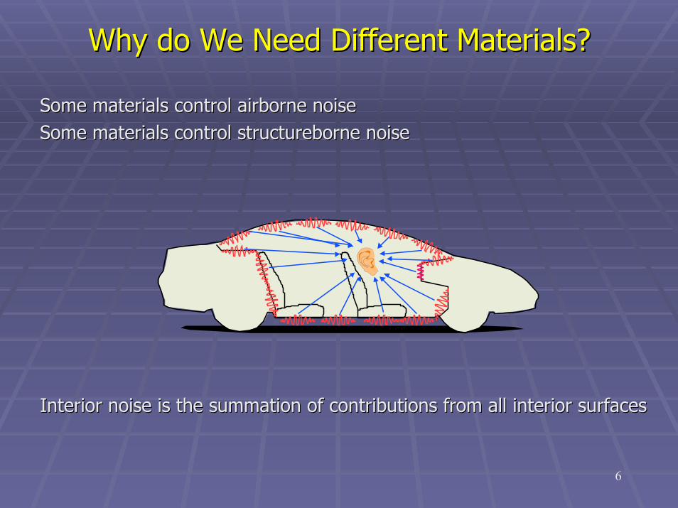
Why do We Need Different Materials?Why do We Need Different Materials?
Some materials control airborne noiseSome materials control airborne noiseSome materials control structureborne noiseSome materials control structureborne noise
Interior noise is the summation of contributions from all interiInterior noise is the summation of contributions from all interior surfacesor surfaces
6

How are NVH Materials Used?How are NVH Materials Used?
Materials are converted into products applied throughout the vehMaterials are converted into products applied throughout the vehicleicle
DoorDoorTrimTrimSideSide
CowlCowlUpperUpperCowlCowl
HoodHood
DashDashOuterOuter
DashDashInnerInner
CarpetCarpet
Carpet/VinylCarpet/VinylUnderlaymentUnderlayment
ThrowThrow--ininMatsMats
Rear SeatRear SeatBottomBottom
HeatHeat--BondableBondableDamperDamper
Rear SeatRear SeatStrainerStrainer RearRear
WheelhouseWheelhouse
TrunkTrunkFloorFloor
PressurePressure--SensitiveSensitiveDamperDamper
TrunkTrunkTrimTrim
PackagePackageTrayTray
Rear PillarRear PillarTrimTrim
RearRearQuarterQuarterTrimTrim
= Damper= Damper = Insulator= Insulator = Absorber= Absorber = Insulator & Absorber= Insulator & Absorber
HeadlinerHeadlinerDoorDoorTrimTrimSideSide
CowlCowlUpperUpperCowlCowl
HoodHood
DashDashOuterOuter
DashDashInnerInner
CarpetCarpet
Carpet/VinylCarpet/VinylUnderlaymentUnderlayment
ThrowThrow--ininMatsMats
Rear SeatRear SeatBottomBottom
HeatHeat--BondableBondableDamperDamper
Rear SeatRear SeatStrainerStrainer RearRear
WheelhouseWheelhouse
TrunkTrunkFloorFloor
PressurePressure--SensitiveSensitiveDamperDamper
TrunkTrunkTrimTrim
PackagePackageTrayTray
Rear PillarRear PillarTrimTrim
RearRearQuarterQuarterTrimTrim
= Damper= Damper = Insulator= Insulator = Absorber= Absorber = Insulator & Absorber= Insulator & Absorber
HeadlinerHeadliner

What is a Sound Absorber?What is a Sound Absorber?
A sound absorber controls (or minimizes) the amount of sound refA sound absorber controls (or minimizes) the amount of sound reflected from lected from a surfacea surface
The effectiveness of a sound absorber is measured by the The effectiveness of a sound absorber is measured by the sound absorption sound absorption coefficientcoefficient which is the ratio of sound energy absorbed by a material which is the ratio of sound energy absorbed by a material surface to the sound energy incident upon the surfacesurface to the sound energy incident upon the surface
surfacethat onincident energy acousticsurfaceaby absorbedenergy acoustic
=α
The sound absorption coefficient ranges from The sound absorption coefficient ranges from 0% to 100% and varies with frequency, 0% to 100% and varies with frequency,
based on the material propertiesbased on the material properties
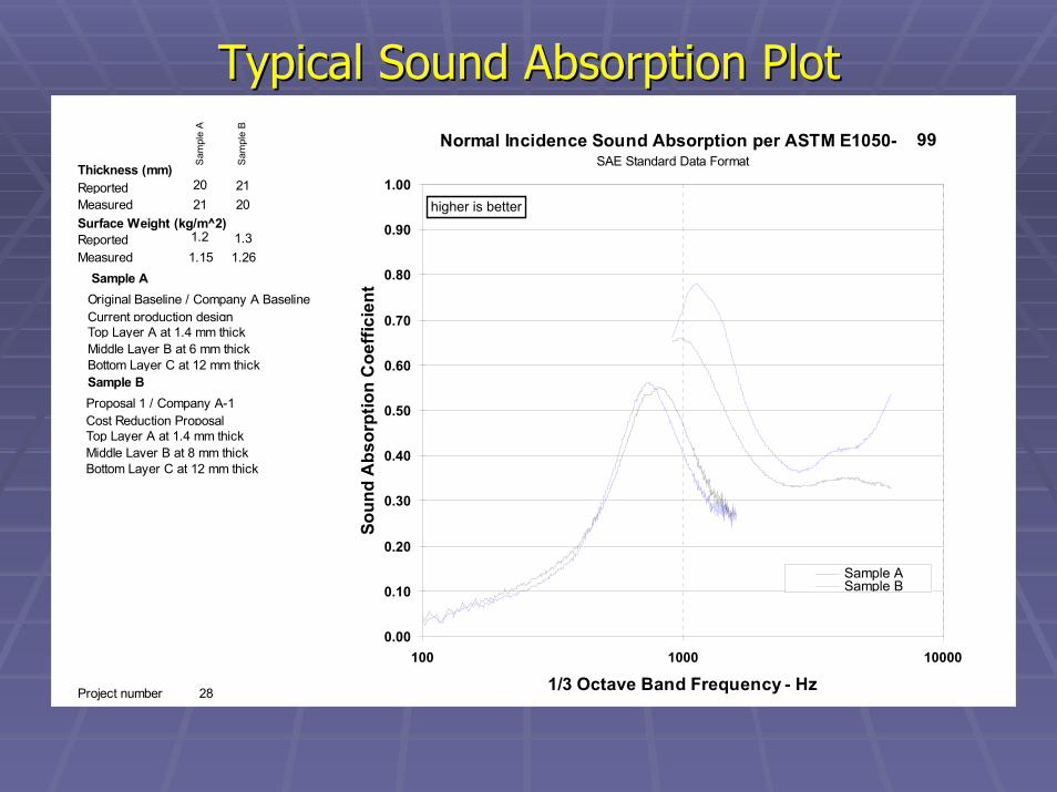
Typical Sound Absorption PlotTypical Sound Absorption Plot
0.00
0.10
0.20
0.30
0.40
0.50
0.60
0.70
0.80
0.90
1.00
100 1000 10000
1/3 Octave Band Frequency - Hz
Soun
d A
bsor
ptio
n C
oeffi
cien
t
Sample ASample B
Normal Incidence Sound Absorption per ASTM E1050-
higher is better
Original Baseline / Company A BaselineCurrent production designTop Layer A at 1.4 mm thick
Sample A
Project number 28
SAE Standard Data Format
Middle Layer B at 6 mm thickBottom Layer C at 12 mm thick
Proposal 1 / Company A-1Cost Reduction ProposalTop Layer A at 1.4 mm thick
Sample B
Middle Layer B at 8 mm thickBottom Layer C at 12 mm thick
MeasuredReported
Sam
ple
A
Sam
ple
B
20202121
MeasuredReported 1.2
1.261.151.3
Surface Weight (kg/m^2)
Thickness (mm)
99

Absorption dissipates noise once it has entered the vehicleAbsorption dissipates noise once it has entered the vehicle
The mechanism of sound absorption is thermal and viscous dissipaThe mechanism of sound absorption is thermal and viscous dissipation tion of sound energy passing through the materialof sound energy passing through the material
A sound absorber reduces reflected/reverberant sound but not theA sound absorber reduces reflected/reverberant sound but not thedirect sound to the receiverdirect sound to the receiver
How does Sound Absorption Contribute to How does Sound Absorption Contribute to Vehicle Noise Control?Vehicle Noise Control?

What Characteristics of Materials make them Absorptive?
Effective sound absorbers are usually porous, with performance iEffective sound absorbers are usually porous, with performance increasing ncreasing with thicknesswith thickness. . Important material properties include the following:Important material properties include the following:
••PorosityPorosity is the percent open area within the material is the percent open area within the material -- it allows the sound it allows the sound waves to propagate into the materialwaves to propagate into the material
••TortuosityTortuosity is the property that prevents direct flow through the materialis the property that prevents direct flow through the material
••Flow ResistanceFlow Resistance is the result of porosity,is the result of porosity, tortuositytortuosity, and cell structure of a , and cell structure of a material and is often a good measure of how absorptive a materiamaterial and is often a good measure of how absorptive a material will be.l will be.
In general, smaller fiber diameters or In general, smaller fiber diameters or smaller cell sizes create higher smaller cell sizes create higher
viscous drag and increase the flow viscous drag and increase the flow resistanceresistance
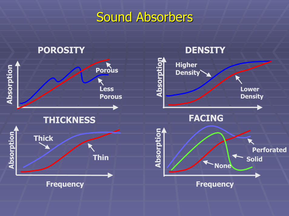
Sound AbsorbersSound Absorbers
DENSITY
Abs
orpt
ion
Lower Density
Higher Density
Frequency
THICKNESS
Abs
orpt
ion
Thin
Thick
Frequency
Abs
orpt
ion
SolidNone
Perforated
FACING
Porous
POROSITY
Less Porous
Abs
orpt
ion

Sound AbsorbersSound AbsorbersTypical sound absorbing materialsTypical sound absorbing materials
•• Fibers Fibers -- recycled cotton, glass fibers, thermoplastic fibersrecycled cotton, glass fibers, thermoplastic fibers•• Foams Foams -- open cell polyurethanesopen cell polyurethanes•• Membrane absorbers Membrane absorbers -- light weight membranes for tuned light weight membranes for tuned
performance over a specific frequency rangeperformance over a specific frequency range•• Hybrid constructions Hybrid constructions --
•• 1/4 wavelength cavities for high performance over a narrow 1/4 wavelength cavities for high performance over a narrow frequency bandfrequency band
•• dual density constructions for a balance of absorption and dual density constructions for a balance of absorption and transmission losstransmission loss
•• Micro denier fibers Micro denier fibers -- porous materials with high internal surface porous materials with high internal surface areaarea
Sound absorbing productsSound absorbing products•• Engine side treatments, headliners, floor systems, dash Engine side treatments, headliners, floor systems, dash
insulatorsinsulators
What is a Sound Barrier?What is a Sound Barrier?
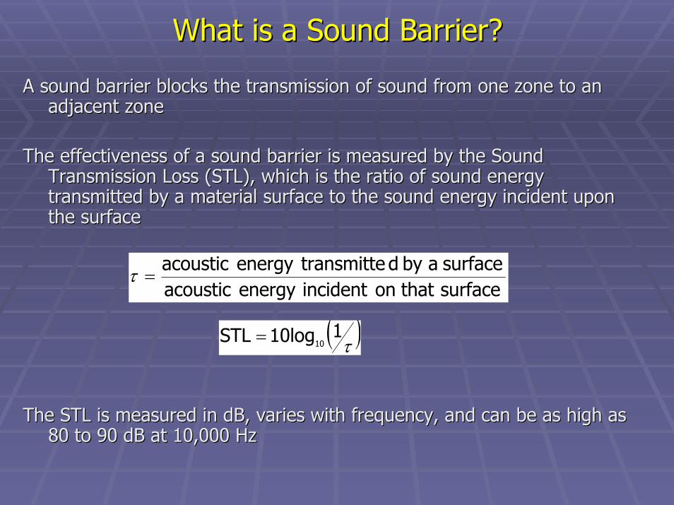
A sound barrier blocks the transmission of sound from one zone tA sound barrier blocks the transmission of sound from one zone to an o an adjacent zoneadjacent zone
The effectiveness of a sound barrier is measured by the Sound The effectiveness of a sound barrier is measured by the Sound Transmission Loss (STL), which is the ratio of sound energy Transmission Loss (STL), which is the ratio of sound energy transmitted by a material surface to the sound energy incident utransmitted by a material surface to the sound energy incident upon pon the surfacethe surface
The STL is measured in dB, varies with frequency, and can be as The STL is measured in dB, varies with frequency, and can be as high as high as 80 to 90 dB at 10,000 Hz
surfacethat onincident energy acousticsurfaceaby dtransmitteenergy acoustic
=τ
( )τ110log STL 10=
80 to 90 dB at 10,000 Hz
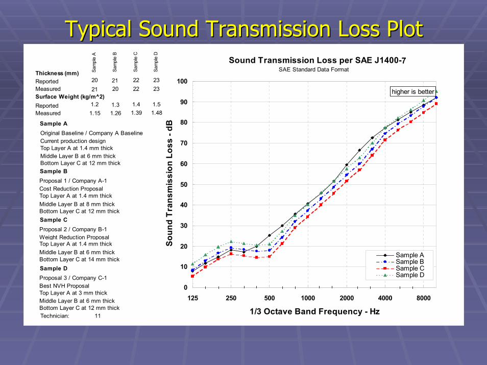
Typical Sound Transmission Loss PlotTypical Sound Transmission Loss Plot
0
10
20
30
40
50
60
70
80
90
100
125 250 500 1000 2000 4000 8000
1/3 Octave Band Frequency - Hz
Soun
d Tr
ansm
issi
on L
oss
- dB
Sample ASample BSample CSample D
Sound Transmission Loss per SAE J1400-
higher is better
Original Baseline / Company A BaselineCurrent production designTop Layer A at 1.4 mm thick
Sample A
Technician: 11
SAE Standard Data Format
Middle Layer B at 6 mm thickBottom Layer C at 12 mm thick
Proposal 1 / Company A-1Cost Reduction ProposalTop Layer A at 1.4 mm thick
Sample B
Middle Layer B at 8 mm thickBottom Layer C at 12 mm thick
Proposal 2 / Company B-1Weight Reduction ProposalTop Layer A at 1.4 mm thick
Sample C
Middle Layer B at 6 mm thickBottom Layer C at 14 mm thick
Proposal 3 / Company C-1Best NVH ProposalTop Layer A at 3 mm thick
Sample D
Middle Layer B at 6 mm thickBottom Layer C at 12 mm thick
MeasuredReported
Sam
ple
A
Sam
ple
B
Sam
ple
C
Sam
ple
D
2023222021232221
MeasuredReported 1.2
1.481.391.261.151.51.41.3
Surface Weight (kg/m^2)
Thickness (mm)
7

How does STL Contribute to Vehicle Noise Control?How does STL Contribute to Vehicle Noise Control?
••STL prevents noise from entering the vehicle, by acting as a barSTL prevents noise from entering the vehicle, by acting as a barrier. rier.
••The mass of the material prevents incident sound waves from beinThe mass of the material prevents incident sound waves from being g transmitted through the material, and minimizes the propagation transmitted through the material, and minimizes the propagation of of sound waves to the other side sound waves to the other side
••This equation is called the (single wall) mass law equation This equation is called the (single wall) mass law equation
STL = 20 logSTL = 20 log1010 ((fwfw) ) -- 4747
Where: f is frequency, HzWhere: f is frequency, Hzw is surface density, kg/m^2w is surface density, kg/m^2

What Characteristics of Materials make them What Characteristics of Materials make them Effective Barriers to Noise?Effective Barriers to Noise?
NonNon--porousporous materials provide an impervious barrier for sound materials provide an impervious barrier for sound transmission. transmission.
MassiveMassive materials with greater surface density more effectively block materials with greater surface density more effectively block transmission of sound waves striking the surface.transmission of sound waves striking the surface.
LimpLimp materials prevent resonance effects. A limp material is relatimaterials prevent resonance effects. A limp material is relatively vely free offree of resonancesresonances (while a stiff material may ring like a bell!)(while a stiff material may ring like a bell!)
Double wallDouble wall mass systems with a mass systems with a decoupler decoupler between mass layers are between mass layers are more effective than a single mass layer of the same weightmore effective than a single mass layer of the same weight

Sound Transmission Loss of Single Wall and Sound Transmission Loss of Single Wall and Double Wall ConstructionsDouble Wall Constructions
Wave Coincidence & Stiffness ControlledRegions
Frequency
Stiffness &ResonanceControlledRegions
Mass Controlled Region
Soun
d Tr
ansm
issi
on L
oss
(dB)
fc
Resonance
Double Wall (mass=2m)12 to 18 dB/Octave
fdw
Single Wall (mass=m)

Sound BarriersSound BarriersThe best sound barriers have high mass per surface area and inclThe best sound barriers have high mass per surface area and include a ude a
decouplerdecoupler between the mass layersbetween the mass layers
Typical barrier materialsTypical barrier materials•• Thermoplastic barriers with fillers (high mass per surface area)Thermoplastic barriers with fillers (high mass per surface area)•• Barriers with fiber or foam Barriers with fiber or foam decouplersdecouplers•• Fiber/mastic/fiber constructionsFiber/mastic/fiber constructions•• Lightweight impervious membranes Lightweight impervious membranes
Barrier productsBarrier products•• Floor systems, dash insulators, cavity sealers Floor systems, dash insulators, cavity sealers

When is a Sound Barrier not a Barrier?When is a Sound Barrier not a Barrier?
Holes in a barrier or gaps at edges can significantly reduce TL Holes in a barrier or gaps at edges can significantly reduce TL performanceperformance
When holes are present, other materials can provide an offset toWhen holes are present, other materials can provide an offset to the leak the leak •• Design solutions Design solutions -- boots, sealing, improved fitboots, sealing, improved fit•• Light weight barriers with high sound absorption
Transmission Loss with Leaks
0
5
10
15
20
25
30
35
40
0 10 20 30 40
Original transmission loss
Resu
lting
tran
smis
sion
loss
0% leaks0.1% leaks0.25% leaks0.5% leaks1.0% leaks
Light weight barriers with high sound absorption
What is a Damping Material?What is a Damping Material?
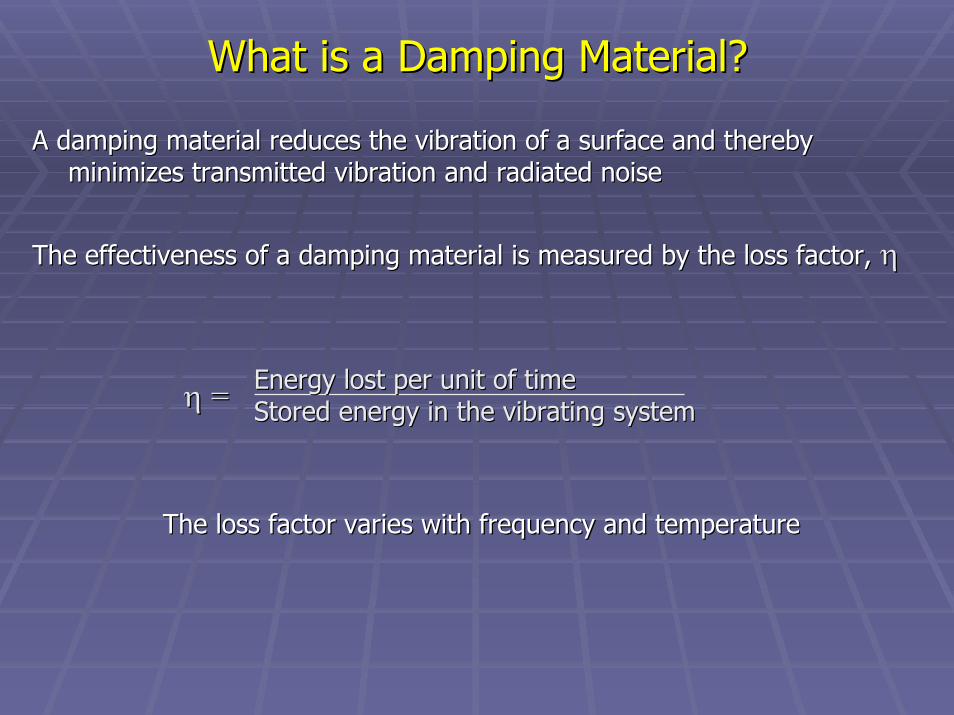
A damping material reduces the vibration of a surface and therebA damping material reduces the vibration of a surface and thereby y minimizes transmitted vibration and radiated noiseminimizes transmitted vibration and radiated noise
The effectiveness of a damping material is measured by the loss The effectiveness of a damping material is measured by the loss factor, factor, ηη
The loss factor varies with frequency and temperatureThe loss factor varies wit
Energy lost per unit of timeEnergy lost per unit of timeStored energy in the vibrating systemStored energy in the vibrating systemηη ==
h frequency and temperature
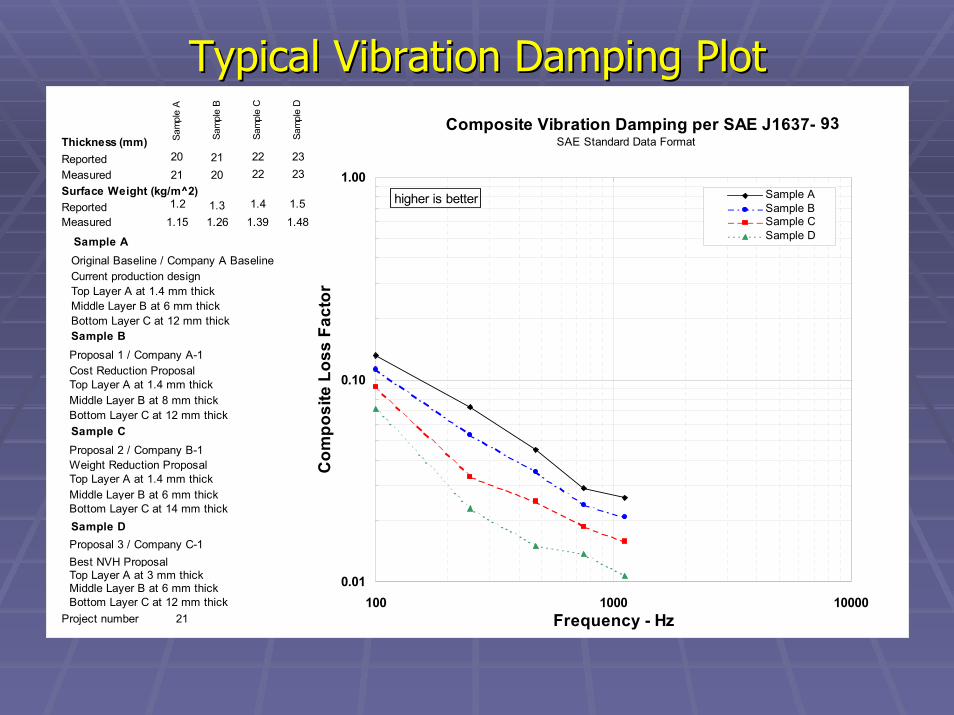
Typical Vibration Damping PlotTypical Vibration Damping PlotComposite Vibration Damping per SAE J1637-
0.01
0.10
1.00
100 1000 10000Frequency - Hz
Com
posi
te L
oss
Fact
or
Sample ASample BSample CSample D
higher is better
Original Baseline / Company A BaselineCurrent production designTop Layer A at 1.4 mm thick
Sample A
Project number 21
Middle Layer B at 6 mm thickBottom Layer C at 12 mm thick
Proposal 1 / Company A-1Cost Reduction ProposalTop Layer A at 1.4 mm thick
Sample B
Middle Layer B at 8 mm thickBottom Layer C at 12 mm thick
Proposal 2 / Company B-1Weight Reduction ProposalTop Layer A at 1.4 mm thick
Sample C
Middle Layer B at 6 mm thickBottom Layer C at 14 mm thick
Proposal 3 / Company C-1Best NVH ProposalTop Layer A at 3 mm thick
Sample D
Middle Layer B at 6 mm thickBottom Layer C at 12 mm thick
MeasuredReported
Sam
ple
A
Sam
ple
B
Sam
ple
C
Sam
ple
D
2023222021232221
MeasuredReported 1.2
1.481.391.261.151.51.41.3
Surface Weight (kg/m^2)
Thickness (mm)93
SAE Standard Data Format
How does Damping Contribute to How does Damping Contribute to Vehicle Noise Reduction?Vehicle Noise Reduction?
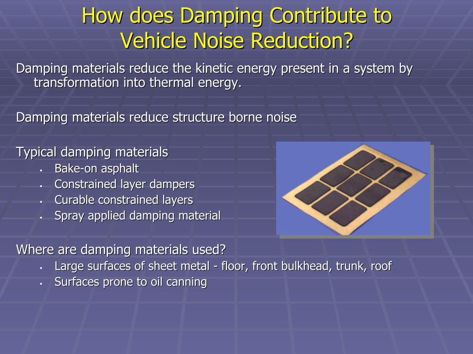
Damping materials reduce the kinetic energy present in a system Damping materials reduce the kinetic energy present in a system by by transformation into thermal energy. transformation into thermal energy.
Damping materials reduce structure borne noiseDamping materials reduce structure borne noise
Typical damping materials Typical damping materials •• BakeBake--on asphalton asphalt•• Constrained layer dampersConstrained layer dampers•• Curable constrained layersCurable constrained layers•• Spray applied damping materialSpray applied damping material
Where are damping materials used?Where are damping materials used?•• Large surfaces of sheet metal Large surfaces of sheet metal -- floor, front bulkhead, trunk, rooffloor, front bulkhead, trunk, roof•• Surfaces prone to oil canning Surfaces prone to oil canning

What is a Vibration Isolator?What is a Vibration Isolator?
A vibration isolator reduces the vibration energy transmitted thA vibration isolator reduces the vibration energy transmitted through a rough a systemsystem
The effectiveness of a vibration isolator is measured by the traThe effectiveness of a vibration isolator is measured by the transmissibility nsmissibility ratio, which ranges from 0 to 10 or more, depending on frequencyratio, which ranges from 0 to 10 or more, depending on frequency
Isolation must be analyzed with respect to the natural vibrationIsolation must be analyzed with respect to the natural vibration or or resonance of the spring/mass system.resonance of the spring/mass system.

Vibration IsolationVibration Isolation
Vibration Transmissibility
0
1
2
3
4
5
0 1 2 3 4
Frequency Ratio
Tans
mis
sibi
lity
Rat
ior = 0.0r = 0.2r = 0.3r = 0.9
Resonance occurs where the frequency ratio is 1.0 Resonance occurs where the frequency ratio is 1.0 Isolation in the resonance region requires dampingIsolation in the resonance region requires damping

How does Vibration Isolation Contribute to How does Vibration Isolation Contribute to Vehicle Noise Control?Vehicle Noise Control?
Vibration isolators reduce structureborne vibration which can prVibration isolators reduce structureborne vibration which can propagate opagate throughout the vehicle and be converted into noise when a vibratthroughout the vehicle and be converted into noise when a vibrating ing surface becomes an efficient radiating panel surface becomes an efficient radiating panel
Isolation requires soft springs to lower the resonant frequency Isolation requires soft springs to lower the resonant frequency and allow and allow operation above the area of resonanceoperation above the area of resonance
Most isolators have a compliant element (spring) and a damper (iMost isolators have a compliant element (spring) and a damper (internal nternal losses or separate damper)losses or separate damper)

Vibration IsolatorsVibration Isolators
Typical vibration isolatorsTypical vibration isolators•• SpringsSprings•• Springs with dampersSprings with dampers•• ElastomericElastomeric mountsmounts•• Fluid filled mountsFluid filled mounts•• SwitchableSwitchable dampersdampers•• Semi active systemsSemi active systems
Vibration isolator productsVibration isolator products•• Engine mountsEngine mounts•• Suspension mountsSuspension mounts•• Body mountsBody mounts
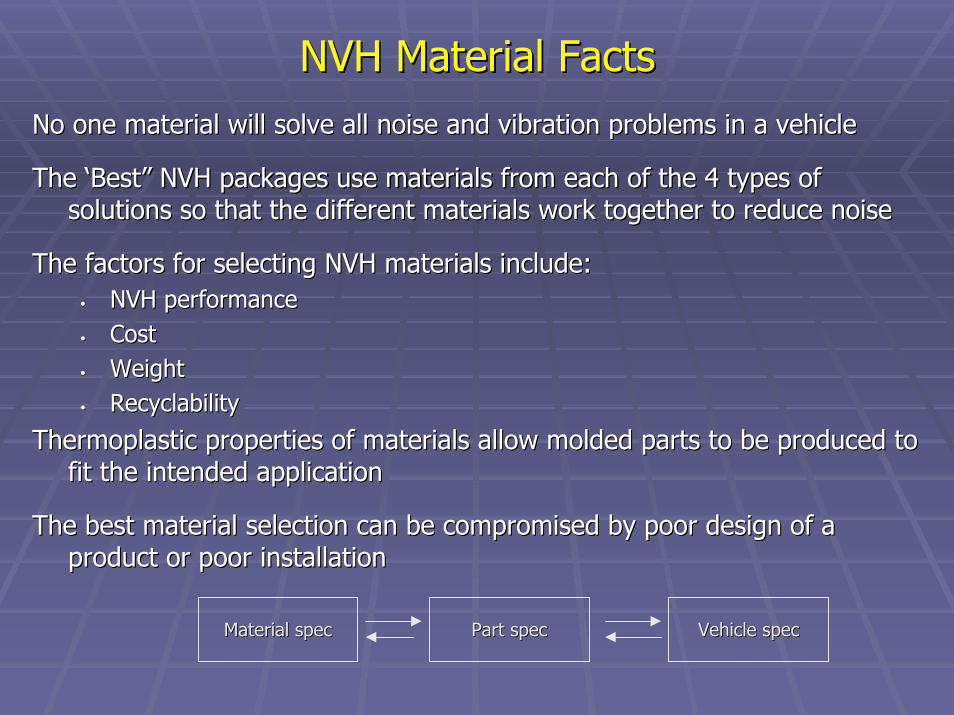
NVH Material FactsNVH Material FactsNo one material will solve all noise and vibration problems in aNo one material will solve all noise and vibration problems in a vehiclevehicle
The ‘Best” NVH packages use materials from each of the 4 types oThe ‘Best” NVH packages use materials from each of the 4 types of f solutions so that the different materials work together to reducsolutions so that the different materials work together to reduce noisee noise
The factors for selecting NVH materials include:The factors for selecting NVH materials include:•• NVH performance NVH performance •• CostCost•• WeightWeight•• RecyclabilityRecyclability
Thermoplastic properties of materials allow molded parts to be pThermoplastic properties of materials allow molded parts to be produced to roduced to fit the intended applicationfit the intended application
The best material selection can be compromised by poor design ofThe best material selection can be compromised by poor design of a a product or poor installationproduct or poor installation
Material specMaterial spec Part specPart spec Vehicle specVehicle spec

Acoustical Material DevelopmentAcoustical Material Development
New technology under development includes:New technology under development includes:
•• Sound absorbers with tunable frequency responseSound absorbers with tunable frequency response
•• Barriers with tunable transmission lossBarriers with tunable transmission loss
•• Hybrid, lightweight materials with a balance of sound absorptionHybrid, lightweight materials with a balance of sound absorption and and transmission losstransmission loss
•• Damping materials with extended temperature rangeDamping materials with extended temperature range
•• Adaptable or SemiAdaptable or Semi--active vibration systemsactive vibration systems
•• Active noise and vibration reduction systemsActive noise and vibration reduction systems
NVH Material QuestionsNVH Material Questions
How do we evaluate the performance of acoustical materials?
This is the subject of Part II
Test Methods for Determining Performance Test Methods for Determining Performance of Acoustical Materialsof Acoustical Materials
Peggy Hoult

Test Methods for Determining Test Methods for Determining Performance of Acoustical MaterialsPerformance of Acoustical Materials
Peggy HoultPeggy HoultRieter Automotive North America, Inc.Rieter Automotive North America, Inc.

What NVH Issues does the Vehicle Exhibit?What NVH Issues does the Vehicle Exhibit?
How do we determine what those issues are?How do we determine what those issues are?
•• By means of a vehicle test.By means of a vehicle test.
How do we know what materials will work in the vehicle to How do we know what materials will work in the vehicle to resolve the NVH issues?resolve the NVH issues?
•• We test the vehicle and we test the materials.We test the vehicle and we test the materials.
Tire/Road
Powertrain
HVAC
Traffic
Exhaust
Wind

Test MethodsTest MethodsAbsorptionAbsorption
What are the different types of measured absorption?What are the different types of measured absorption?
Normal incidence absorption Normal incidence absorption -- impedance tubeimpedance tube•• Test specifications:Test specifications: ASTM C384ASTM C384
ASTM E1050ASTM E1050
Random incidence absorption Random incidence absorption -- reverberation room (large reverberation room (large or small)or small)
•• Test specifications:Test specifications: ASTM C423ASTM C423
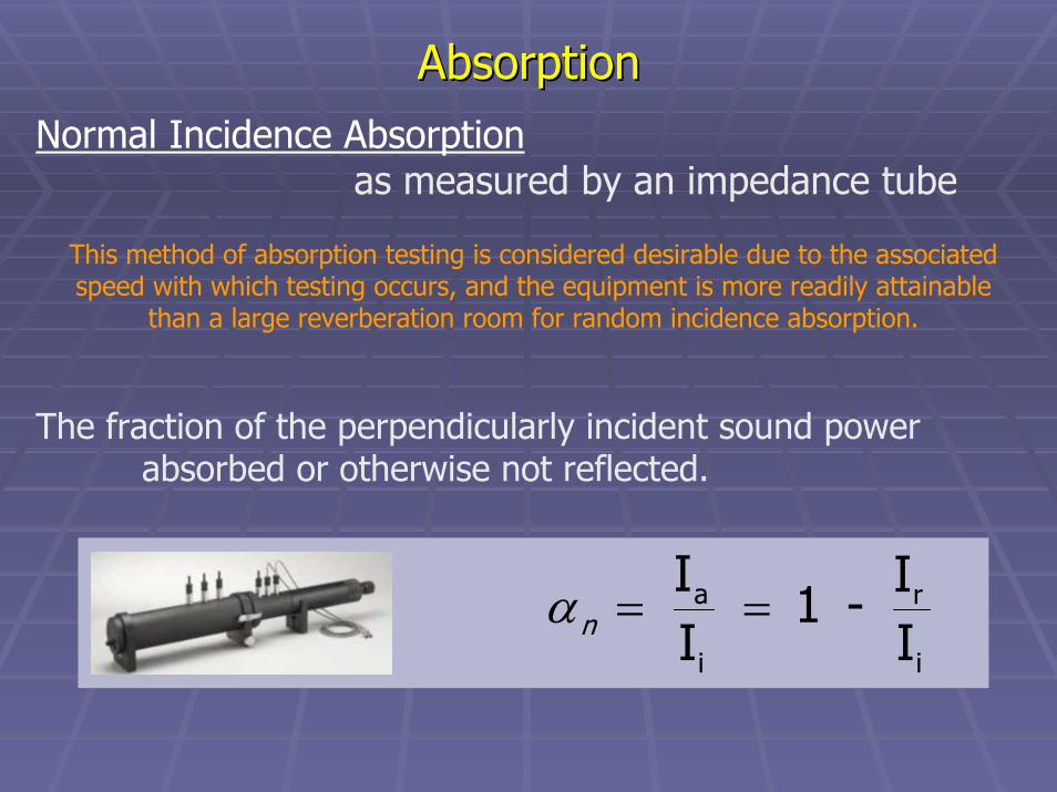
AbsorptionAbsorptionNormal Incidence Absorption
as measured by an impedance tube
This method of absorption testing is considered desirable due to the associatedspeed with which testing occurs, and the equipment is more readily attainable
than a large reverberation room for random incidence absorption.
The fraction of the perpendicularly incident sound powerabsorbed or otherwise not reflected.
i
r
i
a
II - 1
II
==nα

ASTM C384 Test Method
Normal Incidence AbsorptionNormal Incidence Absorption
A plane wave traveling in one direction down a tube is reflected back bythe test sample and produces a standing wave along which pressure ismeasured.
Procedure:Test sample is placed at one end of tube against massive metal reflector. Generate electronically a pure tone at opposite end. Move the microphone to measure maximum and minimum pressures in tube. Compute normal incidence.
( )2minmax
minmax
PPP4P
+=nα
Normal Incidence AbsorptionNormal Incidence Absorption
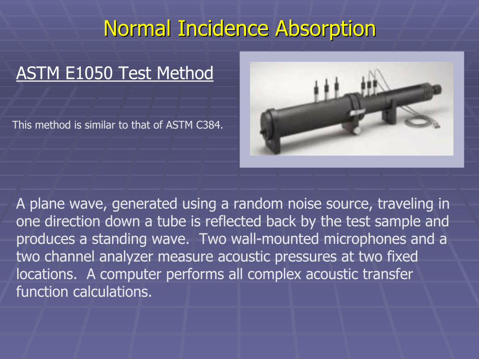
ASTM E1050 Test Method
This method is similar to that of ASTM C384.
A plane wave, generated using a random noise source, traveling in one direction down a tube is reflected back by the test sample and produces a standing wave. Two wall-mounted microphones and a two channel analyzer measure acoustic pressures at two fixed locations. A computer performs all complex acoustic transfer function calculations.
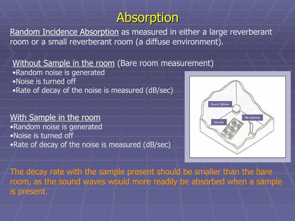
AbsorptionAbsorptionRandom Incidence Absorption as measured in either a large reverberant room or a small reverberant room (a diffuse environment).
Without Sample in the room (Bare room measurement)•Random noise is generated•Noise is turned off•Rate of decay of the noise is measured (dB/sec)
With Sample in the room•Random noise is generated•Noise is turned off•Rate of decay of the noise is measured (dB/sec)
The decay rate with the sample present should be smaller than the bare room, as the sound waves would more readily be absorbed when a sample is present.

Random Incidence AbsorptionRandom Incidence Absorption
Absorption of the room (with or without sample) is calculated by:
Time
Dec
ibel ∆ t
∆ dB
Decay Rate = ∆ dB∆ tdB/sec decay, of RateD
m/sec sound, of Speedcm room, ionreverberat of VolumeV
Sabins metric absorption SoundAwhere
cVD0.921A
3
===
=
=
If the sound absorption of the empty room is A1 and the room with the sample is A2 (metric Sabins), the sound absorption coefficient of the test sample is given by:
( )2
12
m sample, the of area surface S
SAA
=
−=α

AbsorptionAbsorption
Cautions/Advisories:
• Environmental conditions impact measurement results (humidity, temperature, barometric pressure)
• Room architecture (non-diffuse)• Sample size and fit (appropriate for room size)• Sample orientation (too close to reflective surface)• Air gaps (additional absorption due to air)• Edge effects (increasing absorptive area)• Different results are generated from different facilities• Flow resistance as one guide to understanding material absorption
characteristic of materials and components

AbsorptionAbsorption
SAE Round Robin Study of Small Sample Reverberation Room
SAE Acoustical Materials Committee is conducting a study of absorptionperformance of different sized reverberation rooms with the objectiveof standardization of small sample room testing.
ASTM C423 was developed initially for non-automotive applicationswhere the specimen size was significantly larger.
The associated frequency ranges and sample sizes of smaller reverberationrooms are components of this study.

What are the Different Types of Measured What are the Different Types of Measured Sound Transmission Loss (STL)?Sound Transmission Loss (STL)?
•SAE J1400 Method
•ASTM E90 Method
•Sound Intensity Method
In all cases:
STL = 10 log ( 1 / τ )where τ = Sound Transmission Coefficient : the fraction of the airborne sound power incident on a partition that is transmitted by the partition and radiated to the other side.

Sound Transmission LossSound Transmission LossSound Transmission Loss as measured by the SAE J1400 method:
SAE J1400 – Laboratory Measurement of the Airborne Sound Barrier Performance of Automotive Materials and Assemblies
STL measurements incorporate a diffuse reverberant source room, an hemi-anechoic receiving room, and a test specimen between.
Reference Sample (homogeneous limp panel)
•Random noise is generated•SPL is measured in source room and anechoic receiving room
Test Specimen
•Random noise is generated•SPL is measured in source room and anechoic receiving room

Sound Transmission LossSound Transmission Loss
SAE J1400
STL(reference) = 20 log W + 20 log f - 47 (dB)
W = Surface Weight (kg/m2)f = Center Frequency (Hz)
CF = MNR(reference) - STL(reference)
C F = Correlation Factor (relevant to test opening and room conditions)MNR = Measured Noise Reduction
STL(specimen) = MNR(specimen) - CF
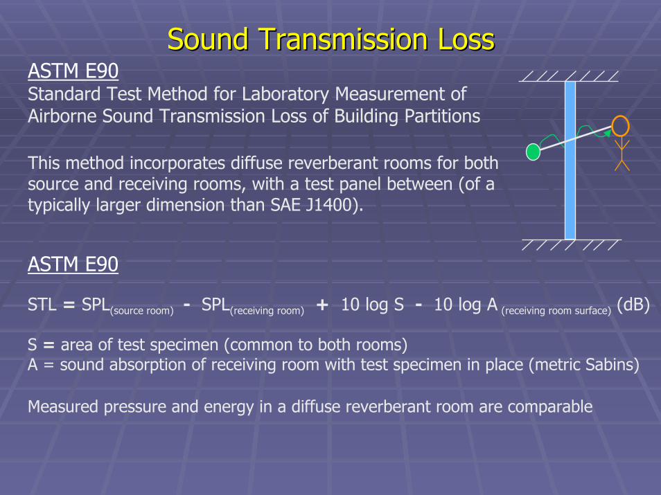
Sound Transmission LossSound Transmission LossASTM E90Standard Test Method for Laboratory Measurement ofAirborne Sound Transmission Loss of Building Partitions
ASTM E90
STL = SPL(source room) - SPL(receiving room) + 10 log S - 10 log A (receiving room surface) (dB)
S = area of test specimen (common to both rooms)A = sound absorption of receiving room with test specimen in place (metric Sabins)
Measured pressure and energy in a diffuse reverberant room are comparable
This method incorporates diffuse reverberant rooms for both source and receiving rooms, with a test panel between (of a typically larger dimension than SAE J1400).
Sound Transmission LossSound Transmission Loss
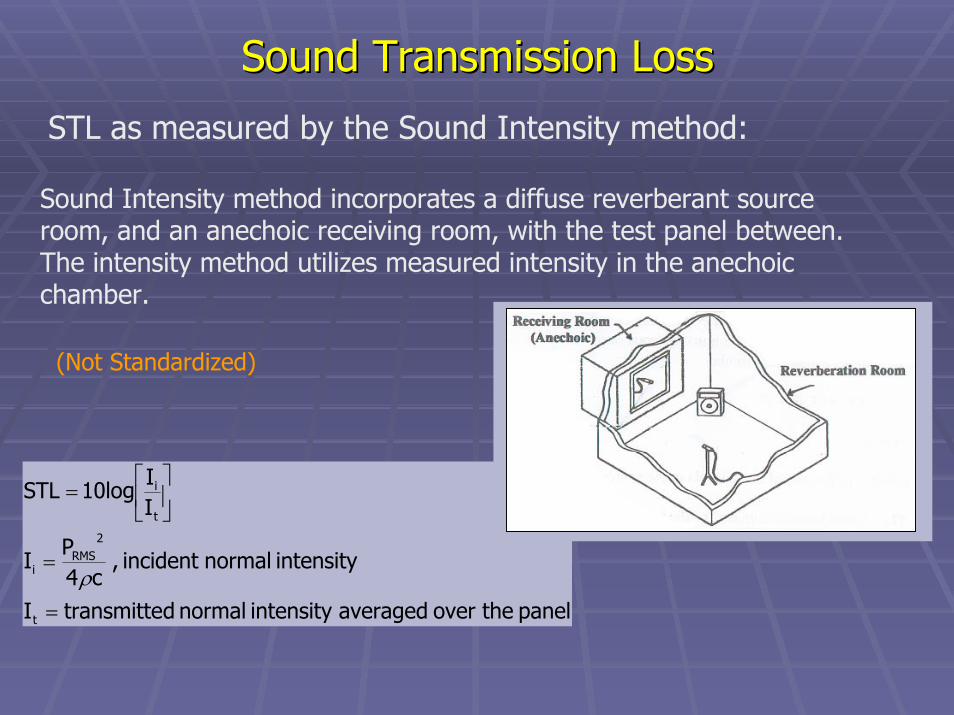
STL as measured by the Sound Intensity method:
Sound Intensity method incorporates a diffuse reverberant sourceroom, and an anechoic receiving room, with the test panel between. The intensity method utilizes measured intensity in the anechoicchamber.
panel theover averagedintensity normal dtransmitte I
intensity normalincident , c4
PI
II
10log STL
t
2RMS
i
t
i
=
=
=
ρ
(Not Standardized)

Sound Transmission LossSound Transmission Loss
Cautions/Advisories:
• Sealing• Holes• Air gaps• Edge• Importance of appropriate sample sizes and fit• Environmental conditions:
• Temperature, humidity, barometric pressure• Room considerations• Sample orientation

Sound Transmission LossSound Transmission Loss
0
10
20
30
40
50
60
70
80
90
125 250 500 1000 2000 4000 8000
1/3 Octave Band Frequency - Hz
Soun
d Tr
ansm
issi
on L
oss
-dB
Sample ASample B
Sound Transmission Loss per SAE J1400-90Effect of Leakage on STL
higher is better
Double wall sample - everything Normal1a
Test A Description
Same Double wall sample - no frame no 4a
Test B Description
Test C Description
Test D Description
MeasuredReported
Sample A
Sample B
0 0
MeasuredReportedMass (kg)
Thickness (mm)

Sound Transmission LossSound Transmission LossInsertion Loss and Noise Reduction ≠ Sound Transmission Loss
Insertion LossThe difference in sound pressure levels measured at a receiverlocation with and without the sound package treatment in place.
Noise ReductionThe difference in sound pressure levels measured on the source side and the receiver side of a sound package treatment (i.e. P-over-P).
Neither are Standardized
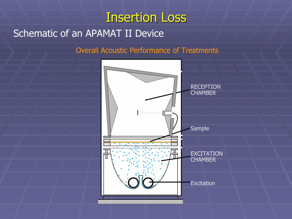
Insertion LossInsertion LossSchematic of an APAMAT II Device
Overall Acoustic Performance of Treatments
Excitation
EXCITATIONCHAMBER
Sample
RECEPTIONCHAMBER

Insertion LossInsertion LossSchematic of an Acoustic Gravelometer
Ball Loading Trough
Glass Balls
Source Chamber
Test Sample
Receiving Camber (Anechoic)
Microphone
Sample Clamping Frame

Damping loss factor (η) is the measure by which the amount of damping is determined. The loss factor is the ratio of the dissipated energy of the system to the entire energy of the system.
η = ∆f/fc
How are damping metrics communicated?DampingDamping
Damping Broadens Response Spikes
Frequency
Response
fc
3 dB
∆f
Half Power Technique
A higher loss factor (η > 0.1) means better damping

DampingDampingHow is the damping loss factor measured?
SAE J1637 MethodLaboratory Measurement of the Composite Vibration Damping Properties of Materials on a Supporting Steel Bar
ASTM E756 MethodStandard Test Method for Measuring Vibration-Damping Properties of Materials
NOTE: SAE J1637 method prescribes the measuring of the composite loss factor,whereas ASTM E756 is for the measurement of the independent material.
SAE J1637 was developed after ASTM E756, but specifies the bar material, size, and mounting conditions which impact the results of the test.
x Different Oberst bars provide different loss factor results o

DampingDampingMeasuring Material Damping Properties
SAE J1637 ASTM E756
Oberst Bar
Steel Bar
Motion Transducer Damping
Material
Exciter Transducer
•Excite the damped bar at ...•Particular modes of vibration•Temperatures of interest
•Determine the resonant frequency
•Measure the lower and upper frequencies (3 dB down from resonant frequency)
•Calculate Damping Loss Factor η = ∆f/fc
•Repeat for other modes and temperatures of interest

DampingDampingSchematic of an RTC III Test Fixture (Rayonnement des Toles de Carrosserie)
Radiation of Body Sheetmetal
Non-Standardized
EXCITER
PANELACCEL.
FRAMEACCEL.
MICROPHONE
Performance of treatments regarding structure-borneexcitation
Flat, Beaded and Curved
plates

DampingDampingSchematic of another Schematic of another Panel Vibration Test RigVibration Test Rig
Non-Standardized
Accelerometer Test Panel
Frame
Shaker

Vibration IsolationVibration IsolationTest Fixture Used for Vibration Isolation Measurements
Non-StandardizedAccelerometers
Holding PlateLoading Plate
Test Sample
Shaker
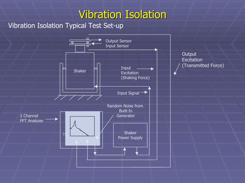
ShakerPower Supply
Random Noise from Built-In
Generator
InputExcitation(Shaking Force)
Input Signal
Output SensorInput Sensor
x x
TRf
2 ChannelFFT Analyzer
OutputExcitation(Transmitted Force)
Shaker
Vibration Isolation Typical Test Set-upVibration IsolationVibration Isolation
NVH Material QuestionsNVH Material Questions
How can materials and data show benefits in the vehicle application?
This is the subject of Part III
Predicting the Performance of Acoustical MaterialsJerome E. Manning
Predicting the Performance of Predicting the Performance of Acoustical MaterialsAcoustical Materials
Jerome E. ManningJerome E. Manning
Cambridge Collaborative, Inc.Cambridge Collaborative, Inc.

Why Bother to PredictWhy Bother to Predict
Mathematical models allow performance and cost goals to be Mathematical models allow performance and cost goals to be reached without expensive vehicle tests.reached without expensive vehicle tests.
“What If” studies can be conducted easily and quickly.“What If” studies can be conducted easily and quickly.
Optimum designs can be achieved.Optimum designs can be achieved.

ChallengeChallenge
•• Can we predict vehicle noise using mathematical models?Can we predict vehicle noise using mathematical models?
•• What acoustical material properties do we need to What acoustical material properties do we need to measure?measure?
•• What accuracy is expected?What accuracy is expected?
•• How should these models be used?How should these models be used?

Vehicle Noise SourcesVehicle Noise Sources
Wind noise
Engine noiseExhaust noise
Road noise
The sound package reduces noise inside the vehicle by using The sound package reduces noise inside the vehicle by using acoustical materials to increase sound absorption and decrease acoustical materials to increase sound absorption and decrease sound transmission.sound transmission.
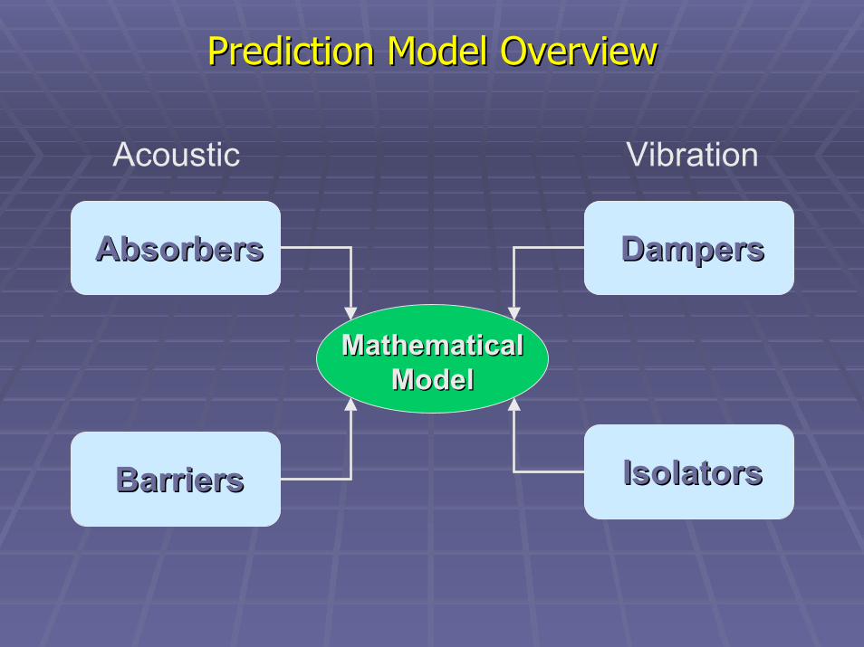
VibrationAcoustic
Prediction Model OverviewPrediction Model Overview
Mathematical Mathematical ModelModel
AbsorbersAbsorbers
BarriersBarriers
DampersDampers
IsolatorsIsolators

Prediction Technique OverviewPrediction Technique Overview
Finite Element / Boundary Element AnalysisFinite Element / Boundary Element Analysis
Low frequencies Low frequencies -- below ~200 Hz for vehicle NVHbelow ~200 Hz for vehicle NVHDifficult to model damping and absorptionDifficult to model damping and absorption
Statistical Energy AnalysisStatistical Energy AnalysisHigh frequencies High frequencies -- above ~200 Hz for vehicle NVHabove ~200 Hz for vehicle NVHProvides only a statistical estimate of responseProvides only a statistical estimate of response
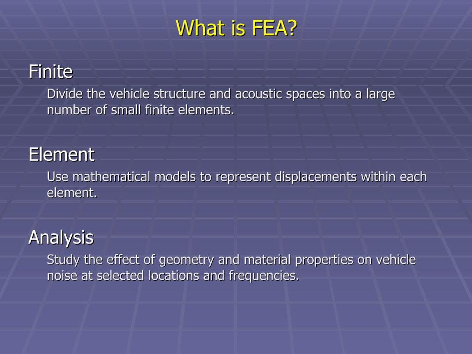
FiniteFiniteDivide the vehicle structure and acoustic spaces into a large Divide the vehicle structure and acoustic spaces into a large number of small finite elements.number of small finite elements.
ElementElementUse mathematical models to represent displacements within each Use mathematical models to represent displacements within each element.element.
AnalysisAnalysisStudy the effect of geometry and material properties on vehicle Study the effect of geometry and material properties on vehicle noise at selected locations and frequencies.noise at selected locations and frequencies.
What is FEA?What is FEA?

StatisticalStatisticalTTake a statistical approach to the description of systems and theake a statistical approach to the description of systems and their ir dynamic properties.dynamic properties.
EnergyEnergyFFollow the flow of structural and acoustic energy through the ollow the flow of structural and acoustic energy through the system.system.
AnalysisAnalysisProvide a framework for the study of dynamical systems.Provide a framework for the study of dynamical systems.
What is SEA?What is SEA?
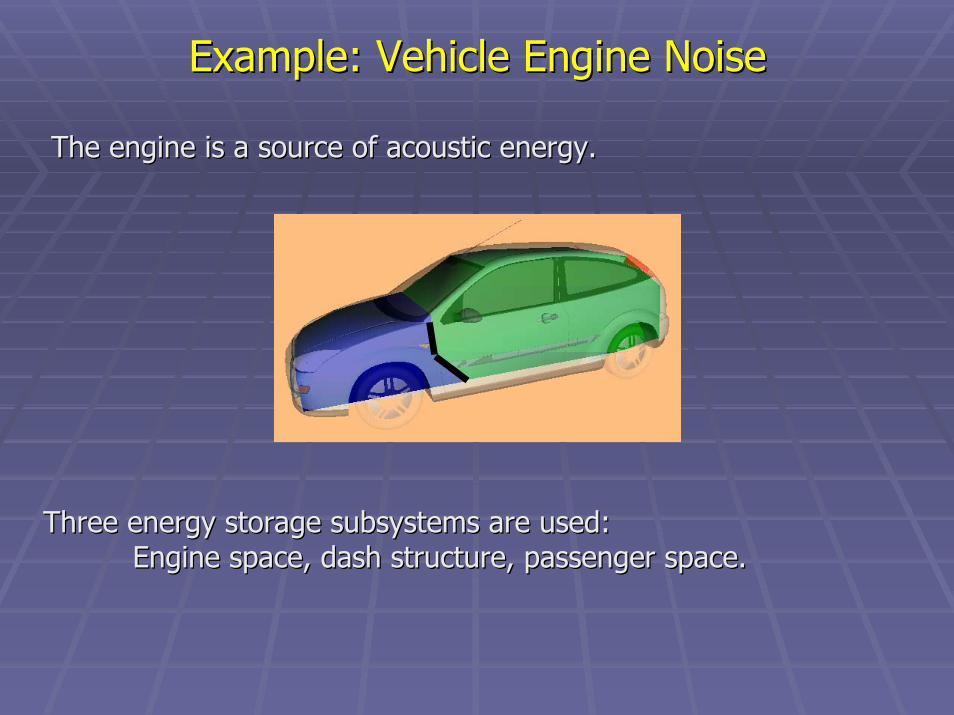
The engine is a source of acoustic energy.The engine is a source of acoustic energy.
Example: Vehicle Engine NoiseExample: Vehicle Engine Noise
Three energy storage subsystems are used: Three energy storage subsystems are used: Engine space, dash structure, passenger space.Engine space, dash structure, passenger space.
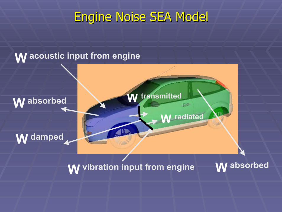
Engine Noise SEA ModelEngine Noise SEA Model
W acoustic input from engine
W transmittedW absorbed
W radiated
W damped
W absorbedW vibration input from engine

SEA Power BalanceSEA Power Balance
acoustic power acoustic power radiated by engine
Passenger Passenger SpaceSpace
power dissipated power dissipated by interior sound by interior sound
packagepackage
Engine Engine SpaceSpace
power dissipated power dissipated by hood linerby hood liner
radiated by engine
Dash Dash StructureStructure
vibration power vibration power through engine through engine
mountsmounts
power dissipated power dissipated by vibration by vibration treatmenttreatment

acousticabsorptiono
diss EV4AcW α
=
SEA Acoustic Energy DissipationSEA Acoustic Energy Dissipation
The absorption coefficient, The absorption coefficient, aa, controls the dissipation of acoustic , controls the dissipation of acoustic energy in an acoustic space.energy in an acoustic space.

SEA Vibration Energy DissipationSEA Vibration Energy Dissipation
The damping loss factor, The damping loss factor, ηη, controls the dissipation , controls the dissipation of vibration energy of a structure.of vibration energy of a structure.
vibrationdampingdiss EW ωη=

SEA Coupling Loss FactorsSEA Coupling Loss Factors
The coupling factor, The coupling factor, ηη, controls the power flow between , controls the power flow between connected subsystems.connected subsystems.
rs;rsr;strans EEW ωη−ωη=
The coupling factor is related to the transmission coefficient, The coupling factor is related to the transmission coefficient, t,t,and the transmission loss, TLand the transmission loss, TL..
τ
ω
=ηs
r;ssr;s V4
Sc
τ=
1log10TL 10

Power Balance for engine compartment, ePower Balance for engine compartment, e
Set of Linear SEA EquationsSet of Linear SEA Equations
( ) inputepe;pde;dep;ed;ee W1EEE
ω=η−η−η+η+η
Power Balance for dash structure, dPower Balance for dash structure, d
( ) inputdpd;ped;edp;de;dd W1EEE
ω=η−η−η+η+η
Power Balance for passenger space, pPower Balance for passenger space, p
( ) 0EEE ep;edp;dpe;pd;pp =η−η−η+η+η
SEA Model AccuracySEA Model Accuracy
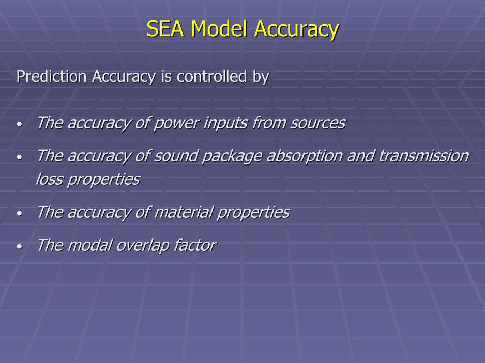
Prediction Accuracy is controlled byPrediction Accuracy is controlled by
•• The accuracy of power inputs from sourcesThe accuracy of power inputs from sources
•• The accuracy of sound package absorption and transmission The accuracy of sound package absorption and transmission loss propertiesloss properties
•• The accuracy of material propertiesThe accuracy of material properties
•• The modal overlap factorThe modal overlap factor
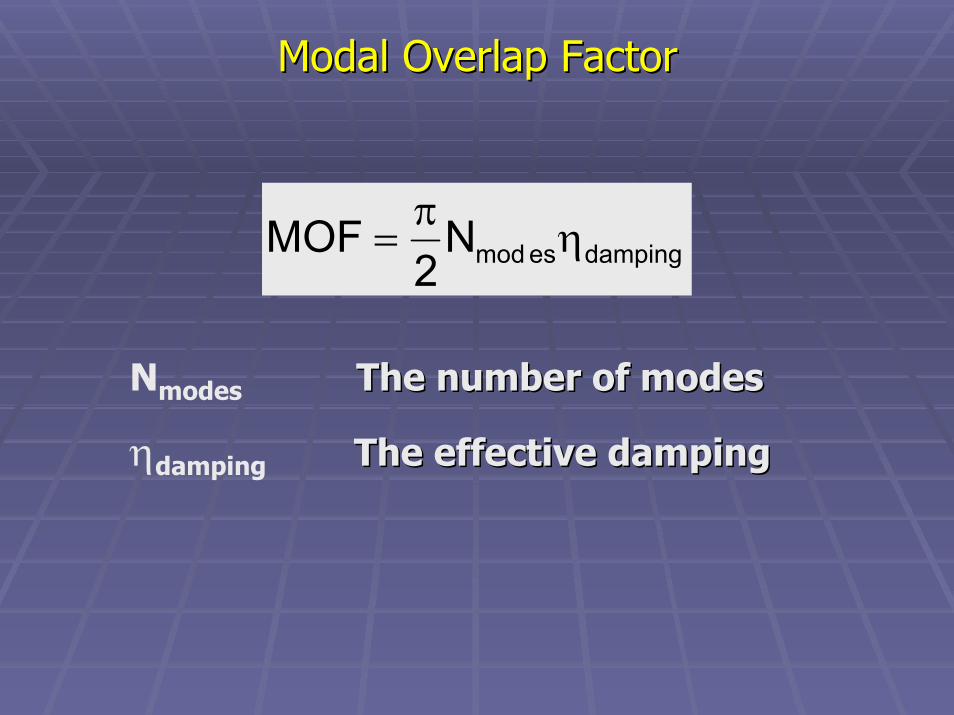
Modal Overlap FactorModal Overlap Factor
dampingesmodN2
MOF ηπ
=
Nmodes The number of modesThe number of modes
ηdamping The effective dampingThe effective damping

Vehicle Floor SEA SubsystemsVehicle Floor SEA Subsystems
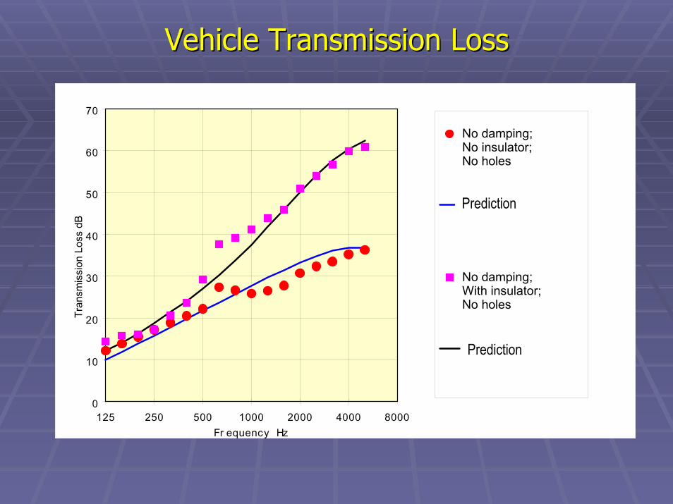
0
10
20
30
40
50
60
70
125 250 500 1000 2000 4000 8000Fr equency Hz
Tran
smis
sion
Los
s dB
No damping; No insulator; No holes
SEAM Prediction
No damping; With insulator; No holes
SEAM Prediction
Vehicle Transmission LossVehicle Transmission Loss
Prediction
Prediction

0
10
20
30
40
50
60
70
125 250 500 1000 2000 4000 8000Fr equency Hz
Tran
smis
sion
Los
s dB
No damping; With insulator; No holes
SEAM Prediction
No damping; With insulator; With holes;
SEAM Prediction
Prediction
Prediction
Effect of Penetrations (Holes)Effect of Penetrations (Holes)

Model Development TimeModel Development Time
•• Simple SEA models to predict component sound Simple SEA models to predict component sound transmission loss.transmission loss.
•• Models to predict airborne noise.Models to predict airborne noise.
•• Complete vehicle models with both airborne and structureComplete vehicle models with both airborne and structure--borne noise paths.borne noise paths.
1 to 3 days
3 to 4 weeks
2 to 3 months

ConclusionsConclusions
•• We can predict vehicle noise using mathematical We can predict vehicle noise using mathematical SEA models.SEA models.
•• Accurate prediction requires accurate Accurate prediction requires accurate measurement of acoustical material properties.measurement of acoustical material properties.
•• Accuracy of 3 dB in 1/3 octave bands is expected.Accuracy of 3 dB in 1/3 octave bands is expected.
•• Models are best used for parameter studies.Models are best used for parameter studies.

ChallengeChallenge
•• Do results from material measurements correlate Do results from material measurements correlate with results from component and vehicle with results from component and vehicle measurements?measurements?
•• If not, can we explain why?If not, can we explain why?
Acoustical
Materials Workshop