origami based mechanical metamaterials - … · origami based mechanical metamaterials cheng lv 1,...
TRANSCRIPT

See discussions, stats, and author profiles for this publication at: https://www.researchgate.net/publication/264644526
Origami based Mechanical Metamaterials
Article in Scientific Reports · August 2014
DOI: 10.1038/srep05979 · Source: PubMed
CITATIONS
89
READS
737
5 authors, including:
Some of the authors of this publication are also working on these related projects:
economy View project
Cheng lv
Arizona State University
11 PUBLICATIONS 224 CITATIONS
SEE PROFILE
Deepakshyam Krishnaraju
Arizona State University
2 PUBLICATIONS 222 CITATIONS
SEE PROFILE
Hongyu Yu
Arizona State University
106 PUBLICATIONS 1,533 CITATIONS
SEE PROFILE
Hanqing Jiang
Arizona State University
140 PUBLICATIONS 6,737 CITATIONS
SEE PROFILE
All content following this page was uploaded by Hanqing Jiang on 22 September 2014.
The user has requested enhancement of the downloaded file.
Origami based MechanicalMetamaterialsCheng Lv1, Deepakshyam Krishnaraju1, Goran Konjevod1, Hongyu Yu2 & Hanqing Jiang1
1School for Engineering of Matter, Transport and Energy, Arizona State University, Tempe, AZ 85287 (USA), 2School of Earth andSpace Exploration, School of Electrical, Computer and Energy Engineering, Arizona State University, Tempe, AZ 85287 (USA).
We describe mechanical metamaterials created by folding flat sheets in the tradition of origami, the art ofpaper folding, and study them in terms of their basic geometric and stiffness properties, as well as loadbearing capability. A periodic Miura-ori pattern and a non-periodic Ron Resch pattern were studied.Unexceptional coexistence of positive and negative Poisson’s ratio was reported for Miura-ori pattern,which are consistent with the interesting shear behavior and infinity bulk modulus of the same pattern.Unusually strong load bearing capability of the Ron Resch pattern was found and attributed to the uniqueway of folding. This work paves the way to the study of intriguing properties of origami structures asmechanical metamaterials.
Mechanical metamaterials, the man-made materials with mechanical properties mainly defined by theirstructures instead of the properties of each component, recently have attracted great attention1–4.Origami, creating three-dimensional (3D) structures from two-dimensional (2D) sheets through a
process of folding along creases, provides an interesting source for designing mechanical metamaterials andhas been transformed by mathematicians, scientists, and engineers to utilize the folded objects’ deformability andcompactness in applications ranging from space exploration (e.g., a foldable telescope lens5), to automotive safety(e.g., airbags6), biomedical devices (e.g., heart stent7), and extremely foldable and stretchable electronics8,9.Notable progress has been made in the area of origami theory including tree theory10 and its correspondingcomputer program11, folding along creases12–14, and geometric mechanics of a periodic origami pattern15. Amongclasses of origami patterns, a particular one, namely rigid origami, in which the faces between the creases remainrigid during folding/unfolding and only the creases deform, is different from most origami patterns that requirefaces bending or partial crumpling to make many-step folds. Idealized rigid origami possesses one of the mostobvious advantages of origami in terms of deformation, i.e., the deformation is completely realized by the folding/unfolding at the creases and does not involve any deformation at the rigid faces4. The geometric characteristics,such as the necessary condition around a single vertex for rigid origami16,17 have been studied, and a computersimulator for rigid origami18 exists. There have also been made limited efforts to study the structural character-istics of one particular rigid origami, namely Miura-ori19, as a mechanical metamaterial, with the main focus onthe negative Poisson’s ratio15,20, though these properties can be more rigorously examined. It is noticed that theexisting studies are mainly focused on periodic origami patterns (e.g., Miura-ori); however, non-periodic origamipatterns as mechanical metamaterials have not gained attention yet, partially due to the difficulties in theoreticalanalysis and modeling. To span a much wider spectrum of using rigid origami as mechanical metamaterials, wereport a systematic study of two rigid origami folding patterns, not only the periodic Miura-ori but also a non-periodic Ron Resch folding21 using combined analytical and numerical approaches. Specifically, we rigorouslyaddress the commonly mistaken in-plane Poisson’s ratio of Miura-ori, which was believed to be always negativebut we show here that it can be positive as well, and its physical interpretation. The ubiquitous non-localinteractions between vertices of rigid origami patterns are captured through a non-local finite element approachand the compressive buckling resistance of a Ron Resch tube is studied, which inspires a theoretical andexperimental study of the load bearing capability of the Ron Resch pattern. The result witnesses the superb loadbearing capability of this Ron Resch pattern. Based on the approaches in this paper, mechanical properties ofdifferent rigid origami patterns, both periodic and non-periodic ones, can be readily studied.
ResultsUnit cell and the whole pattern of a Miura-ori. Figure 1a illustrates a Miura-ori (n1, n2) in its folded state,containing n1 (511) vertices in x1 direction and n2 (511) vertices in x2 direction, with x3 as the out-of-plane
OPEN
SUBJECT AREAS:THEORY AND
COMPUTATION
MECHANICAL ENGINEERING
Received19 May 2014
Accepted14 July 2014
Published7 August 2014
Correspondence andrequests for materials
should be addressed toH.J. (hanqing.jiang@
asu.edu)
SCIENTIFIC REPORTS | 4 : 5979 | DOI: 10.1038/srep05979 1
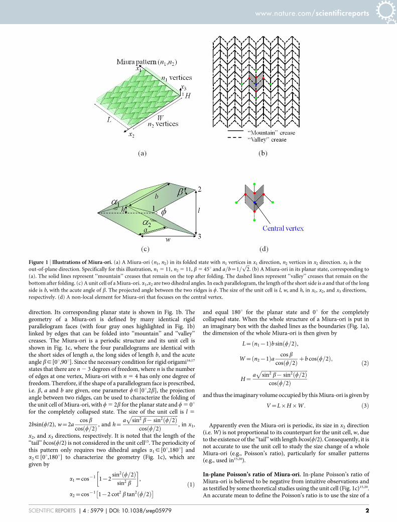
direction. Its corresponding planar state is shown in Fig. 1b. Thegeometry of a Miura-ori is defined by many identical rigidparallelogram faces (with four gray ones highlighted in Fig. 1b)linked by edges that can be folded into ‘‘mountain’’ and ‘‘valley’’creases. The Miura-ori is a periodic structure and its unit cell isshown in Fig. 1c, where the four parallelograms are identical withthe short sides of length a, the long sides of length b, and the acuteangle bg[0u,90u]. Since the necessary condition for rigid origami16,17
states that there are n 2 3 degrees of freedom, where n is the numberof edges at one vertex, Miura-ori with n 5 4 has only one degree offreedom. Therefore, if the shape of a parallelogram face is prescribed,i.e. b, a and b are given, one parameter wg[0u,2b], the projectionangle between two ridges, can be used to characterize the folding ofthe unit cell of Miura-ori, with w 5 2b for the planar state and w 5 0ufor the completely collapsed state. The size of the unit cell is l 5
2bsin(w/2), w~2acos b
cos w=2ð Þ , and h~affiffiffiffiffiffiffiffiffiffiffiffiffiffiffiffiffiffiffiffiffiffiffiffiffiffiffiffiffiffiffiffiffiffiffiffisin2 b{ sin2 w=2ð Þ
pcos w=2ð Þ , in x1,
x2, and x3 directions, respectively. It is noted that the length of the‘‘tail’’ bcos(w/2) is not considered in the unit cell15. The periodicity ofthis pattern only requires two dihedral angles a1g[0u,180u] anda2g[0u,180u] to characterize the geometry (Fig. 1c), which aregiven by
a1~cos{1 1{2sin2 w=2ð Þ
sin2 b
� �,
a2~cos{1 1{2 cot2 b tan2 w=2ð Þ� � ð1Þ
and equal 180u for the planar state and 0u for the completelycollapsed state. When the whole structure of a Miura-ori is put inan imaginary box with the dashed lines as the boundaries (Fig. 1a),the dimension of the whole Miura-ori is then given by
L~ n1{1ð Þb sin w=2ð Þ,
W~ n2{1ð Þa cos b
cos w=2ð Þzb cos w=2ð Þ;
H~affiffiffiffiffiffiffiffiffiffiffiffiffiffiffiffiffiffiffiffiffiffiffiffiffiffiffiffiffiffiffiffiffiffiffiffisin2 b{ sin2 w=2ð Þ
pcos w=2ð Þ
ð2Þ
and thus the imaginary volume occupied by this Miura-ori is given by
V~L|H|W: ð3Þ
Apparently even the Miura-ori is periodic, its size in x2 direction(i.e. W) is not proportional to its counterpart for the unit cell, w, dueto the existence of the ‘‘tail’’ with length bcos(w/2). Consequently, it isnot accurate to use the unit cell to study the size change of a wholeMiura-ori (e.g., Poisson’s ratio), particularly for smaller patterns(e.g., used in15,20).
In-plane Poisson’s ratio of Miura-ori. In-plane Poisson’s ratio ofMiura-ori is believed to be negative from intuitive observations andas testified by some theoretical studies using the unit cell (Fig. 1c)15,20.An accurate mean to define the Poisson’s ratio is to use the size of a
Figure 1 | Illustrations of Miura-ori. (a) A Miura-ori (n1, n2) in its folded state with n1 vertices in x1 direction, n2 vertices in x2 direction. x3 is the
out-of-plane direction. Specifically for this illustration, n1 5 11, n2 5 11, b 5 45u and a=b~1=ffiffiffi2p
. (b) A Miura-ori in its planar state, corresponding to
(a). The solid lines represent ‘‘mountain’’ creases that remain on the top after folding. The dashed lines represent ‘‘valley’’ creases that remain on the
bottom after folding. (c) A unit cell of a Miura-ori. a1,a2 are two dihedral angles. In each parallelogram, the length of the short side is a and that of the long
side is b, with the acute angle of b. The projected angle between the two ridges is w. The size of the unit cell is l, w, and h, in x1, x2, and x3 directions,
respectively. (d) A non-local element for Miura-ori that focuses on the central vertex.
www.nature.com/scientificreports
SCIENTIFIC REPORTS | 4 : 5979 | DOI: 10.1038/srep05979 2
whole Miura-ori, instead of using the unit cell. Specifically, the in-
plane Poisson’s ratio n12 is defined as n12~{e11
e22
����e22?0
, where
e11~dLL
and e22~dWW
are the infinitesimal strains in x1- and x2-
directions, respectively. Using equation (2), the in-plane Poisson’sratio n12 is obtained as
n12~{ cot2 w=2ð Þ n2{1ð Þg cos bz cos2 w=2ð Þn2{1ð Þg cos b{ cos2 w=2ð Þ , ð4Þ
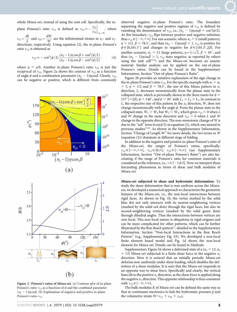
where g 5 a/b. Another in-plane Poisson’s ratio n21 is just thereciprocal of n12. Figure 2a shows the contour of n12 as a functionof angle w and a combination parameter (n2 2 1)gcosb. Clearly, n12
can be negative or positive, which is different from commonly
observed negative in-plane Poisson’s ratio. The boundaryseparating the negative and positive regimes of n12 is defined byvanishing the denominator of n12, i.e., (n2 2 1)gcosb 5 cos2(w/2).At this boundary, n12 flips between positive and negative infinities;thus n12g[2‘,1‘]. For one scenario, where n2 5 5 (small pattern),g 5 1/2, b 5 78.5u, and thus (n2 2 1)gcosb , 1, n12 is positive forwg[0,101.5u] and changes to negative for wg[101.5u,2b]. Foranother scenario, n2 5 13 (large pattern), g~1=
ffiffiffi2p
, b 5 45u, andthus (n2 2 1)gcosb . 1, n12 stays negative, as reported by othersusing the unit cell15,20; and the Miura-ori becomes an auxeticmaterial. Similar analysis can be applied on the out-of-planePoisson’s ratios. Details can be found in the SupplementaryInformation, Section ‘‘Out-of-plane Poisson’s Ratio’’.
Figure 2b provides an intuitive explanation of the sign change inthe in-plane Poisson’s ratio n12. For the specific example with n1 5 n2
5 5, g 5 1/2 and b 5 78.5u, the size of this Miura pattern in x1
direction, L, decreases monotonically from the planar state to thecollapsed state, which is pictorially shown in the three insets for w 5
157u(52b), w 5 140u, and w 5 20u with L1 . L2 . L3. In contrast toL, the respective size of this pattern in the x2 direction, W, does notchange monotonically with the angle w. From the planar state to thecollapsed state, W1 . W2 but W2 , W3, which gives n12 , 0 when Land W change in the same direction and n12 . 0 when L and Wchange in the opposite direction. The non-monotonic change of W isdue to the ‘‘tail’’ term bcos(w/2) in equation (2), which was missed inprevious studies15,20. As shown in the Supplementary Information,Section ‘‘Change of Length W’’ for more details, the two terms in W(equation (2)) dominate at different stage of folding.
In addition to the negative and positive in-plane Poisson’s ratio ofthe Miura-ori, the ranges of Poisson’s ratios, specifically,n12g[2‘,1‘], n13g[0,‘], n23g[2‘,‘] (see SupplementaryInformation, Section ‘‘Out-of-plane Poisson’s Ratio’’) are also fas-cinating if the range of Poisson’s ratio for common materials isconsidered as the reference, i.e., ng[21,0.5]. Now we interpret thesefascinating phenomena in terms of shear and bulk modulus ofMiura-ori.
Miura-ori subjected to shear and hydrostatic deformation. Tostudy the shear deformation that is non-uniform across the Miura-ori, we developed a numerical approach to characterize the geometricfeatures of the Miura-ori, i.e., the non-local interactions betweenrigid faces. As shown in Fig. 1b, the vertex marked by the solidblue dot not only interacts with its nearest-neighboring vertices(marked by the solid red dots) through the rigid faces, but also itssecond-neighboring vertices (marked by the solid green dots)through dihedral angles. Thus the interactions between vertices arenon-local. This non-local nature is ubiquitous in rigid origami andcan be more complicated for other patterns, which can be furtherillustrated by the Ron Resch pattern21, detailed in the SupplementaryInformation, Section ‘‘Non-local Interactions in the Ron ReschPattern’’ (e.g., Supplementary Fig. S3). We developed a non-localfinite element based model and Fig. 1d shows the non-localelement for Miura-ori. Details can be found in Methods.
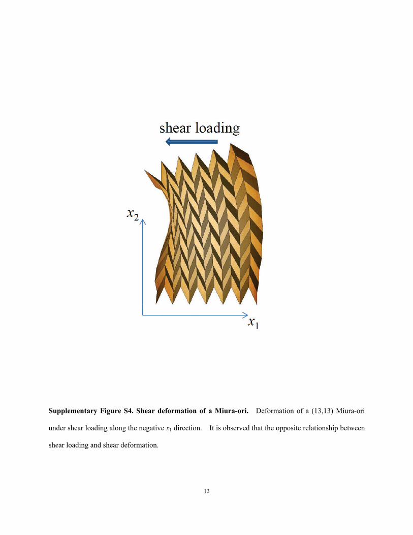
Supplementary Figure S4 shows a deformed state of a (n1 5 13, n2
5 13) Miura-ori subjected to a finite shear force in the negative x1
direction. Here it is noticed that an initially periodic Miura-orideforms non-uniformly under shear loading, which disables the def-inition of a shear modulus. It is seen that the Miura-ori responds inan opposite way to shear force. Specifically and clearly, the verticallines tilt to the positive x1 direction, as the shear force is applied alongthe negative x1 direction. This opposite relationship is thus consistentwith n12g[2‘,1‘].
The bulk modulus K of Miura-ori can be defined the same way asthat in continuum mechanics to link the hydrostatic pressure p andthe volumetric strain h(5e11 1 e22 1 e33),
Figure 2 | Poisson’s ratios of Miura-ori. (a) Contour plot of in-plane
Poisson’s ratio n12 as a function of w and the combined parameter
(n2 2 1)gcosb. (b) Explanation of negative and positive in-plane
Poisson’s ratio n12.
www.nature.com/scientificreports
SCIENTIFIC REPORTS | 4 : 5979 | DOI: 10.1038/srep05979 3
1K
~h
p
����p~0
, ð5Þ
Using the principle of superposition (details given in the Supple-mentary Information, Section ‘‘Bulk Modulus of Miura-ori’’), thebulk modulus K is given by
1K
~1{n21{n31
E11z
1{n12{n32
E22z
1{n13{n23
E33, ð6Þ
where E11~ds11
de11
����de11~0
, E22~ds22
de22
����de22~0
, E33~ds33
de33
����de33~0
are the
tangential moduli of the stress-strain curve. Using the work conjug-
ate relation, stresses are expressed as s11~LWtot
Le11, s22~
LWtot
Le22,
s33~LWtot
Le33, where Wtot 5 Utot/V is the elastic energy density with
Utot given by Supplementary Eq. S2 and V given by equation (3). Asshown in the Supplementary Information, Section ‘‘Range of Tensileand Bulk Modulus’’ for details, the tensile (E11, E22, E33) and bulkmoduli (K) have a wide range of variation and some of them varyfrom 0 to infinity, such as K.
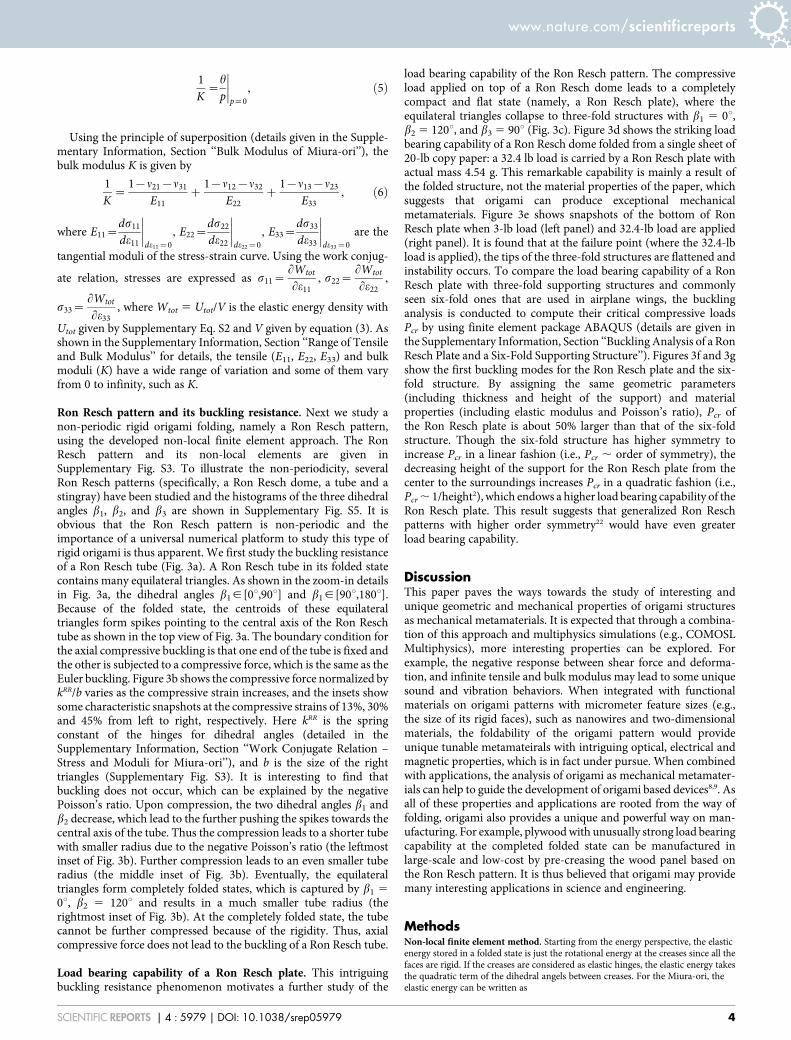
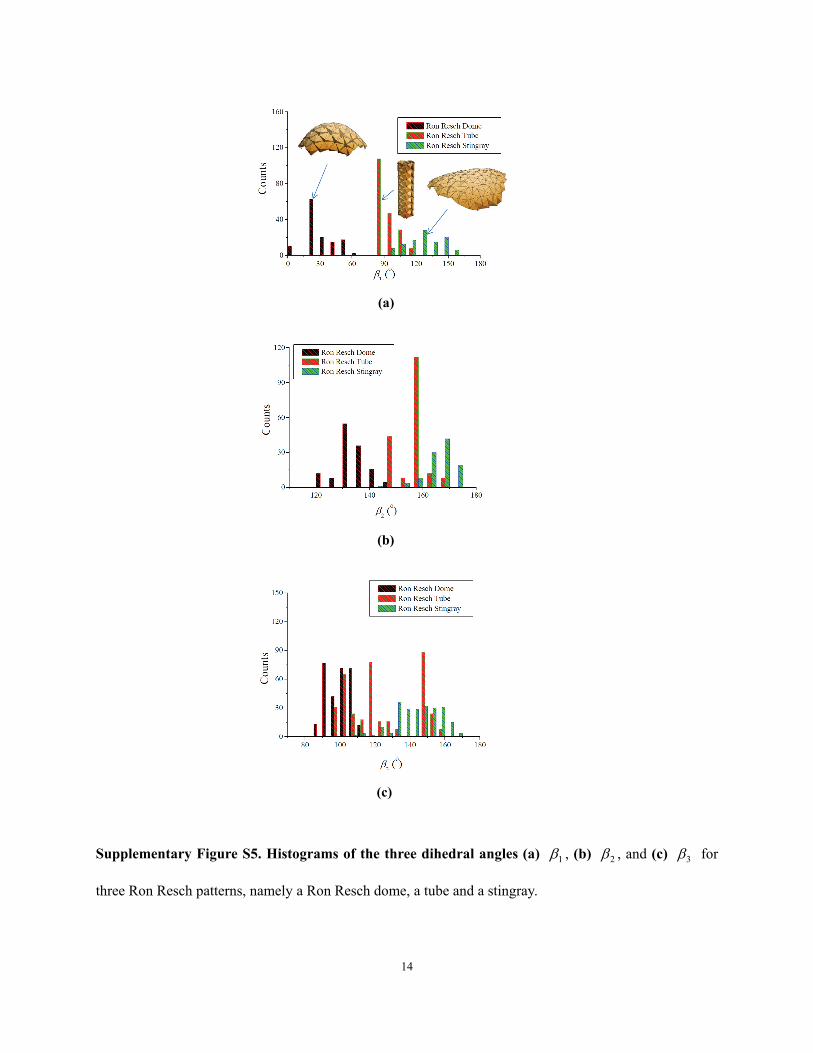
Ron Resch pattern and its buckling resistance. Next we study anon-periodic rigid origami folding, namely a Ron Resch pattern,using the developed non-local finite element approach. The RonResch pattern and its non-local elements are given inSupplementary Fig. S3. To illustrate the non-periodicity, severalRon Resch patterns (specifically, a Ron Resch dome, a tube and astingray) have been studied and the histograms of the three dihedralangles b1, b2, and b3 are shown in Supplementary Fig. S5. It isobvious that the Ron Resch pattern is non-periodic and theimportance of a universal numerical platform to study this type ofrigid origami is thus apparent. We first study the buckling resistanceof a Ron Resch tube (Fig. 3a). A Ron Resch tube in its folded statecontains many equilateral triangles. As shown in the zoom-in detailsin Fig. 3a, the dihedral angles b1g[0u,90u] and b1g[90u,180u].Because of the folded state, the centroids of these equilateraltriangles form spikes pointing to the central axis of the Ron Reschtube as shown in the top view of Fig. 3a. The boundary condition forthe axial compressive buckling is that one end of the tube is fixed andthe other is subjected to a compressive force, which is the same as theEuler buckling. Figure 3b shows the compressive force normalized bykRR/b varies as the compressive strain increases, and the insets showsome characteristic snapshots at the compressive strains of 13%, 30%and 45% from left to right, respectively. Here kRR is the springconstant of the hinges for dihedral angles (detailed in theSupplementary Information, Section ‘‘Work Conjugate Relation –Stress and Moduli for Miura-ori’’), and b is the size of the righttriangles (Supplementary Fig. S3). It is interesting to find thatbuckling does not occur, which can be explained by the negativePoisson’s ratio. Upon compression, the two dihedral angles b1 andb2 decrease, which lead to the further pushing the spikes towards thecentral axis of the tube. Thus the compression leads to a shorter tubewith smaller radius due to the negative Poisson’s ratio (the leftmostinset of Fig. 3b). Further compression leads to an even smaller tuberadius (the middle inset of Fig. 3b). Eventually, the equilateraltriangles form completely folded states, which is captured by b1 5
0u, b2 5 120u and results in a much smaller tube radius (therightmost inset of Fig. 3b). At the completely folded state, the tubecannot be further compressed because of the rigidity. Thus, axialcompressive force does not lead to the buckling of a Ron Resch tube.
Load bearing capability of a Ron Resch plate. This intriguingbuckling resistance phenomenon motivates a further study of the
load bearing capability of the Ron Resch pattern. The compressiveload applied on top of a Ron Resch dome leads to a completelycompact and flat state (namely, a Ron Resch plate), where theequilateral triangles collapse to three-fold structures with b1 5 0u,b2 5 120u, and b3 5 90u (Fig. 3c). Figure 3d shows the striking loadbearing capability of a Ron Resch dome folded from a single sheet of20-lb copy paper: a 32.4 lb load is carried by a Ron Resch plate withactual mass 4.54 g. This remarkable capability is mainly a result ofthe folded structure, not the material properties of the paper, whichsuggests that origami can produce exceptional mechanicalmetamaterials. Figure 3e shows snapshots of the bottom of RonResch plate when 3-lb load (left panel) and 32.4-lb load are applied(right panel). It is found that at the failure point (where the 32.4-lbload is applied), the tips of the three-fold structures are flattened andinstability occurs. To compare the load bearing capability of a RonResch plate with three-fold supporting structures and commonlyseen six-fold ones that are used in airplane wings, the bucklinganalysis is conducted to compute their critical compressive loadsPcr by using finite element package ABAQUS (details are given inthe Supplementary Information, Section ‘‘Buckling Analysis of a RonResch Plate and a Six-Fold Supporting Structure’’). Figures 3f and 3gshow the first buckling modes for the Ron Resch plate and the six-fold structure. By assigning the same geometric parameters(including thickness and height of the support) and materialproperties (including elastic modulus and Poisson’s ratio), Pcr ofthe Ron Resch plate is about 50% larger than that of the six-foldstructure. Though the six-fold structure has higher symmetry toincrease Pcr in a linear fashion (i.e., Pcr , order of symmetry), thedecreasing height of the support for the Ron Resch plate from thecenter to the surroundings increases Pcr in a quadratic fashion (i.e.,Pcr , 1/height2), which endows a higher load bearing capability of theRon Resch plate. This result suggests that generalized Ron Reschpatterns with higher order symmetry22 would have even greaterload bearing capability.
DiscussionThis paper paves the ways towards the study of interesting andunique geometric and mechanical properties of origami structuresas mechanical metamaterials. It is expected that through a combina-tion of this approach and multiphysics simulations (e.g., COMOSLMultiphysics), more interesting properties can be explored. Forexample, the negative response between shear force and deforma-tion, and infinite tensile and bulk modulus may lead to some uniquesound and vibration behaviors. When integrated with functionalmaterials on origami patterns with micrometer feature sizes (e.g.,the size of its rigid faces), such as nanowires and two-dimensionalmaterials, the foldability of the origami pattern would provideunique tunable metamateirals with intriguing optical, electrical andmagnetic properties, which is in fact under pursue. When combinedwith applications, the analysis of origami as mechanical metamater-ials can help to guide the development of origami based devices8,9. Asall of these properties and applications are rooted from the way offolding, origami also provides a unique and powerful way on man-ufacturing. For example, plywood with unusually strong load bearingcapability at the completed folded state can be manufactured inlarge-scale and low-cost by pre-creasing the wood panel based onthe Ron Resch pattern. It is thus believed that origami may providemany interesting applications in science and engineering.
MethodsNon-local finite element method. Starting from the energy perspective, the elasticenergy stored in a folded state is just the rotational energy at the creases since all thefaces are rigid. If the creases are considered as elastic hinges, the elastic energy takesthe quadratic term of the dihedral angels between creases. For the Miura-ori, theelastic energy can be written as
www.nature.com/scientificreports
SCIENTIFIC REPORTS | 4 : 5979 | DOI: 10.1038/srep05979 4
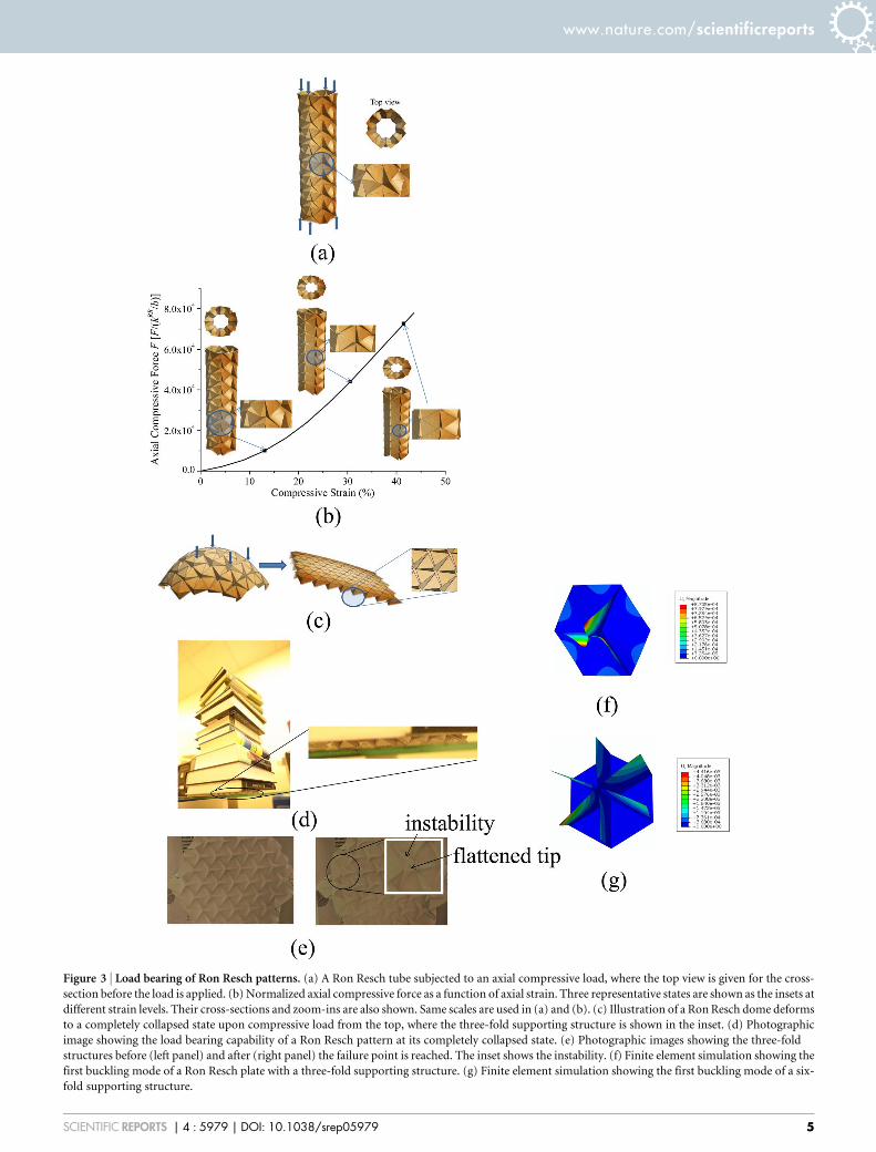
Figure 3 | Load bearing of Ron Resch patterns. (a) A Ron Resch tube subjected to an axial compressive load, where the top view is given for the cross-
section before the load is applied. (b) Normalized axial compressive force as a function of axial strain. Three representative states are shown as the insets at
different strain levels. Their cross-sections and zoom-ins are also shown. Same scales are used in (a) and (b). (c) Illustration of a Ron Resch dome deforms
to a completely collapsed state upon compressive load from the top, where the three-fold supporting structure is shown in the inset. (d) Photographic
image showing the load bearing capability of a Ron Resch pattern at its completely collapsed state. (e) Photographic images showing the three-fold
structures before (left panel) and after (right panel) the failure point is reached. The inset shows the instability. (f) Finite element simulation showing the
first buckling mode of a Ron Resch plate with a three-fold supporting structure. (g) Finite element simulation showing the first buckling mode of a six-
fold supporting structure.
www.nature.com/scientificreports
SCIENTIFIC REPORTS | 4 : 5979 | DOI: 10.1038/srep05979 5
Utotal~X
a1
12
kMo1 a1{a1,eq� 2
zX
a2
12
kMo2 a2{a2,eq� 2
, ð7Þ
where kMo1 and kMo
2 are the spring constants of the hinges for dihedral angles a1 and a2
for Miura-ori (superscript ‘‘Mo’’), respectively; a1,eq and a2,eq are the correspondingdihedral angles for a1 and a2 at the undeformed state (or equivalently, just foldedstate); the summation runs over all dihedral angles. Similarly, the elastic energy can bereadily constructed for the Ron Resch pattern,
Utotal~X
b1
12
kRR1 b1{b1,eq
�2zX
b2
12
kRR2 b2{b2,eq
�2
zX
b3
12
kRR3 b3{b3,eq
�2,
ð8Þ
where the superscript ‘‘RR’’ denotes the Ron Resch pattern and the subscripts have asimilar meaning as explained for the Miura-ori. It is reasonable to takekMo
1 ~kMo2 ~kMo , and kRR
1 ~kRR2 ~kRR
3 ~kRR , for paper folding (although in mostmachine-made papers, the fibers tend to run in one direction and so the hingeconstants for edges running in different directions will be different).
Because the dihedral angles are completely determined by the coordinates ofvertices in rigid origami, the elastic energy can also be expressed as a function ofcoordinates of vertices, i.e., Utotal 5 Utotal(x), where x~ x1,x2, � � � ,xNð ÞT and xi is theposition of a vertex i, and N is the total number of the vertices. When the external load�Fi is applied at vertex i, the total potential energy is Ptotal xð Þ~Utotal{
Xi
�Fi:xi . The
equilibrium state of a rigid origami corresponds to a state of minimum energy and canbe given by
LPtotal
Lx~0, ð9Þ
which needs to be solved to reach the equilibrium state of a rigid origami. There aremany approaches that can be utilized to solve Supplementary Eq. S3, such as theconjugate gradient method and steepest descent method that just use the first deri-vatives of Ptotal, or the finite element method that uses both the first derivative (as the
non-equilibrium force P~{LPtotal
Lx) and the second derivatives (as the stiffness
matrix K~L2Ptotal
LxLx) of Ptotal. The governing equation for the finite element method
is
K:u~P, ð10Þ
where u 5 x 2 x(0) is the displacement of the vertices with x(0) as the initial position ofthe vertices. For nonlinear systems, equation (10) is solved iteratively until theequilibrium characterized by the vanishing non-equilibrium force P 5 0. For discretevertices in rigid origami that has a great deal of similarity with atomic systems, thefinite element method has been extended to capture the non-local interactions23,24.
There are two aspects to consider when the finite element method is used. Firstly, tocalculate the non-equilibrium force P and stiffness matrix K, the elastic energy Utotal
needs to be explicitly written as a function of vertex coordinates, which is detailed inthe Supplementary Information, Section ‘‘Nonlinearity of the Elastic Energy withrespect to the Coordinates of Vertices’’. Therefore, iteration is needed. Secondly, non-local elements are required to capture the non-local interactions within a singleelement. For example, those nine vertices marked by blue, red and green dots inFig. 1d form one non-local element for the Miura-ori, focusing on the central vertexmarked by the blue dot. Similar non-local elements (i.e., all solid circles and opencircles in Supplementary Fig. S3) are constructed for the Ron Resch pattern, as shownin Supplementary Fig. S3. It may be noticed that the definition of non-local elementsdepends on specific rigid origami patterns and in each pattern different elements areformed for different types of vertices. These non-local elements are implemented inthe commercial finite element package, ABAQUS, via its user defined elements(UEL).
1. Bertoldi, K., Reis, P. M., Willshaw, S. & Mullin, T. Negative Poisson’s ratiobehavior induced by an elastic instability. Adv. Mater. 22, 361–366 (2010).
2. Kadic, M., Buckmann, T., Stenger, N., Thiel, M. & Wegener, M. On thepracticability of pentamode mechanical metamaterials. Appl. Phys. Lett. 100,191901 (2012).
3. Lee, J. et al. A mechanical metamaterial made from a DNA hydrogel. Nat.Nanotechnol. 7, 816–820 (2012).
4. Zheng, X. et al. Ultralight, ultrastiff mechanical metamaterials. Science 344,1373–1377 (2014).
5. Gardner, J. P. et al. The James Webb space telescope. Space Sci. Rev. 123, 485–606(2006).
6. Cromvik, C. & Eriksson, K. Airbag folding based on origami mathematics(Chalmers University of Technology, Goteborg, 2006).
7. Kuribayashi, K. et al. Self-deployable origami stent grafts as a biomedicalapplication of Ni-rich TiNi shape memory alloy foil. Mater. Sci. Eng. A-Struct.Mater. Prop. Microstruct. Process. 419, 131–137 (2006).
8. Tang, R. et al. Origami-enabled deformable silicon solar cells. Appl. Phys. Lett.104, 083501 (2014).
9. Song, Z. et al. Origami lithium-ion batteries. Nat. Commun. 5, 3140; doi: 10.1038/ncomms4140 (2014).
10. Lang, R. J. Origami design secrets, 2nd edn (CRC Press, Boca Raton, 2011).11. Lang, R. J. A computational algorithm for origami design. In: Proc. 12th Annual
ACM Symp. on Computational Geometry 98–105 (1996).12. Cerda, E. & Mahadevan, L. Confined developable elastic surfaces: cylinders, cones
and the Elastica. Proc R Soc A-Math. Phys. Eng. Sci. 461, 671–700 (2005).13. Dias, M. A. & Santangelo, C. D. The shape and mechanics of curved fold origami
structures. Europhys. Lett. 100, 54005 (2012).14. Dias, M. A., Dudte, L. H., Mahadevan, L. & Santangelo, C. D. Geometric
mechanics of curved crease origami. Phys. Rev. Lett. 109, 114301 (2012).15. Wei, Z. Y., Guo, Z. V., Dudte, L., Liang, H. Y. & Mahadevan, L. Geometric
mechanics of periodic pleated origami. Phys. Rev. Lett. 110, 215501 (2013).16. Belcastro, S.-M. & Hull, T. C. Modeling the folding of paper into three dimensions
using affine transformations. Linear Algebra Appl. 348, 273–282 (2002).17. Belcastro, S.-M. & Hull, T. C. Origami 3 (A K Peters/CRC Press, Natick, 2002).18. Tachi, T. Simulation of rigid origami. In: Origami 4, Proceedings of 4OSME: 4th
International Conference on Origami Science, Mathematics and Education (ed(edsLang, R. J.) (2009).
19. Miura, K. Method of packaging and deployment of large membranes in space(Institute of Space and Astronomical Sciences, Tokyo, 1985).
20. Schenk, M. & Guest, S. D. Geometry of Miura-folded metamaterials. Proc. Natl.Acad. Sci. U S A 110, 3276–3281 (2013).
21. Resch, R. D., inventor & Resch, R. D., assignee. Self-supporting structural unithaving a series of repetitious geometrical modules. United States patent US3,407,558. 1968 Oct 29.
22. Tachi, T. Designing freeform origami tessellations by generalizing Resch’spatterns. J. Mech. Design 135, 111006 (2013).
23. Liu, B., Huang, Y., Jiang, H., Qu, S. & Hwang, K. C. The atomic-scale finite elementmethod. Comput. Meth. Appl. Mech. Eng. 193, 1849–1864 (2004).
24. Liu, B., Jiang, H., Huang, Y., Qu, S., Yu, M. F. & Hwang, K. C. Atomic-scale finiteelement method in multiscale computation with applications to carbonnanotubes. Phys. Rev. B 72, 035435 (2005).
AcknowledgmentsWe acknowledge the seed grant support from the Office of Associate Dean for Research atIra A. Fulton School of Engineering, and Office of Knowledge Enterprise and Development,Arizona State University.
Author contributionsC.L., D.K. and H.J. carried out and designed experiments and analysis. C.L., D.K. and H.J.wrote the paper. C.L., D.K., G.K., H.Y. and H.J. commented on the paper.
Additional informationSupplementary information accompanies this paper at http://www.nature.com/scientificreports
Competing financial interests: The authors declare no competing financial interests.
How to cite this article: Lv, C., Krishnaraju, D., Konjevod, G., Yu, H. & Jiang, H. Origamibased Mechanical Metamaterials. Sci. Rep. 4, 5979; DOI:10.1038/srep05979 (2014).
This work is licensed under a Creative Commons Attribution-NonCommercial-ShareAlike 4.0 International License. The images or other third party material in thisarticle are included in the article’s Creative Commons license, unless indicatedotherwise in the credit line; if the material is not included under the CreativeCommons license, users will need to obtain permission from the license holderin order to reproduce the material. To view a copy of this license, visit http://creativecommons.org/licenses/by-nc-sa/4.0/
www.nature.com/scientificreports
SCIENTIFIC REPORTS | 4 : 5979 | DOI: 10.1038/srep05979 6
1
Supplementary Information
for
Origami based Mechanical Metamaterials
By Cheng Lv, Deepakshyam Krishnaraju, Goran Konjevod, Hongyu Yu, and Hanqing Jiang*
[*] Prof. H. Jiang, C. Lv, D. Krishnaraju, Dr. G. Konjevod
School for Engineering of Matter, Transport and Energy
Arizona State University, Tempe, AZ 85287 (USA)
E-mail: [email protected]
[*] Prof. H. Yu
School of Earth and Space Exploration
School of Electrical, Computer and Energy Engineering
Arizona State University, Tempe, AZ 85287 (USA)
2
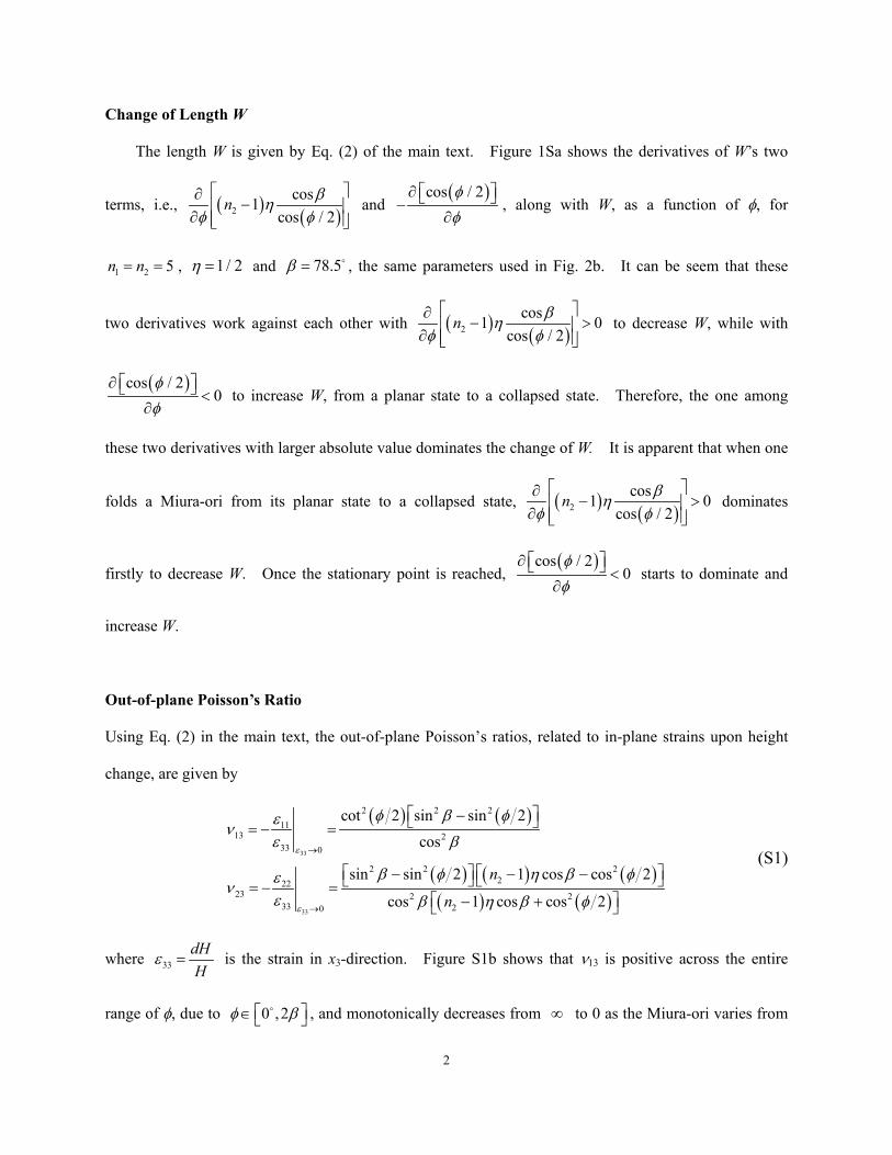
Change of Length W
The length W is given by Eq. (2) of the main text. Figure 1Sa shows the derivatives of W’s two
terms, i.e., ( ) ( )2cos1
cos / 2n βη
φ φ ∂
− ∂
and ( )cos / 2φφ
∂ −∂
, along with W, as a function of φ, for
1 2 5n n= = , 1 / 2η = and 78.5β = , the same parameters used in Fig. 2b. It can be seem that these
two derivatives work against each other with ( ) ( )2cos1 0
cos / 2n βη
φ φ ∂
− > ∂
to decrease W, while with
( )cos / 20
φφ
∂ <∂
to increase W, from a planar state to a collapsed state. Therefore, the one among
these two derivatives with larger absolute value dominates the change of W. It is apparent that when one
folds a Miura-ori from its planar state to a collapsed state, ( ) ( )2cos1 0
cos / 2n βη
φ φ ∂
− > ∂
dominates
firstly to decrease W. Once the stationary point is reached, ( )cos / 2
0φφ
∂ <∂
starts to dominate and
increase W.
Out-of-plane Poisson’s Ratio
Using Eq. (2) in the main text, the out-of-plane Poisson’s ratios, related to in-plane strains upon height
change, are given by
( ) ( )
( ) ( ) ( )( ) ( )
33
33
2 2 211
13 233 0
2 2 2222
23 2 233 20
cot 2 sin sin 2cos
sin sin 2 1 cos cos 2
cos 1 cos cos 2
n
n
ε
ε
φ β φενε β
β φ η β φενε β η β φ
→
→
− = − =
− − − = − = − +
(S1)
where 33dHH
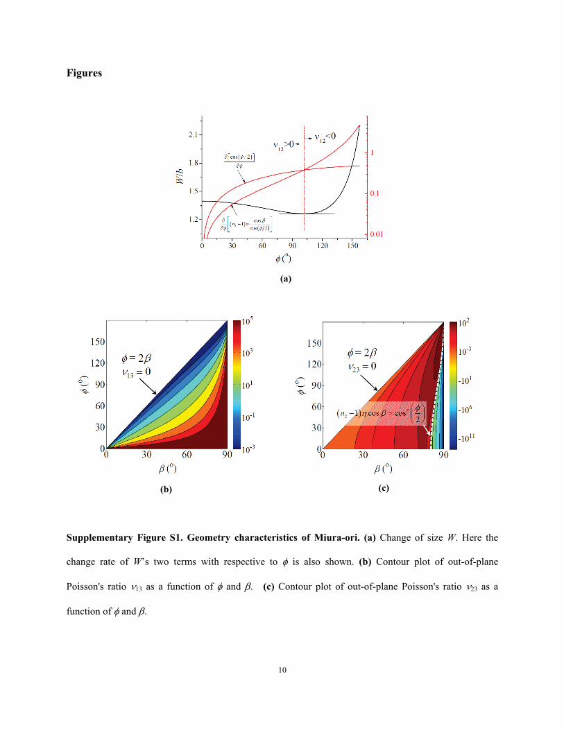
ε = is the strain in x3-direction. Figure S1b shows that ν13 is positive across the entire
range of φ, due to 0 ,2φ β ∈ , and monotonically decreases from ∞ to 0 as the Miura-ori varies from

3
its completely collapsed state ( 0φ = ) to the planar state ( 2φ β= ), i.e., [ ]13 0,ν ∈ ∞ . For an extreme
case when 90β → or 0φ → , 13ν →∞ . Figure S1c shows ν23 for 2 13n = and 0.5η = . It is
observed that 23ν can be both negative and positive, separated by a boundary defined by
( ) ( )22 1 cos cos 2n η β φ− = which is shown as the white dashed line. Figure S1c also shows that
[ ]23 ,ν ∈ −∞ ∞ .
Nonlinearity of the Elastic Energy with respect to the Coordinates of Vertices
Depending on the type of rigid origami and the number of dihedral angles per unit cell, the elastic
energy can be always expressed by
( )2
,1
12
n
i
T
total i i i eqi
U kα
α α=
= −∑∑ , (S2)
where ik are the stiffness constants of the dihedral angles iα with ,i eqα as the equilibrium angle, and
nT is the number of types of dihedral angles. To obtain the stiffness matrix K and non-equilibrium
force P, we need to express totalU in terms of the coordinates of vertices.
Considering the case of Miura-ori where nT =2, the two dihedral angles are given as
( )
( )
21
1 2
1 2 22
sin 2cos 1 2
sin
cos 1 2cot tan 2
φα
β
α β φ
−
−
= −
= −
, (S3)
where φ is the projection angle between two ridges. 0 ,90β ∈ and 0 ,2φ β ∈
. Using the
distances between the three vertices 1, 2, 3 (Fig. 1c) that form this angle, φ can be determined by using
the cosine rule,
2 2 2
1 12 13 23
12 13
cos2
R R RR R
φ − + −=
, (S4)
4
where ijR is the distance between vertices i and j.
By combining Eqs. (S2) to (S4), a relationship between the elastic energy and the coordinates of
vertices can be obtained. Clearly, this relationship is nonlinear, i.e., totalU is nonlinear with respect to
the coordinates of vertices.
Bulk Modulus of Miura-ori
The bulk modulus K of Miura-ori can be defined by
0
1
pK pθ
=
= , (S5)
where p is the hydrostatic pressure. Using the principle of superposition, when only ( )11p σ= is
applied and 22 33 0σ σ= = , we have ( )21 31 111θ ν ν ε= − − , where 11σ , 22σ 33σ are normal stresses in
x1, x2, and x3 directions, respectively. Using a similar approach for 22σ and 33σ , the bulk modulus K
is given by ( ) ( ) ( ) 3311 2221 31 12 32 13 23
11 22 33
1 1 1 1K
εε εν ν ν ν ν νσ σ σ
= − − + − − + − − , where 11 22 33 pσ σ σ= = = .
For vanishing nominal stress 11 22 33 0σ σ σ= = → , the tensile moduli are given by
11 22 33
3311 22
11 11 22 22 33 330 0 0
1 1 1, ,E E Eσ σ σ
εε εσ σ σ
= = =
= = = . (S6)
Thus the bulk modulus K is given by
21 31 12 32 13 23
11 22 33
1 1 11K E E E
ν ν ν ν ν ν− − − − − −= + + . (S7)
Here the tensile moduli are the tangential moduli of the stress-strain curve, i.e.,
11 22 33
3311 2211 22 33
11 22 330 0 0
, , d d d
dd dE E Ed d dε ε ε
σσ σε ε ε
= = =
= = = .
5
Work Conjugate Relation – Stress and Moduli for Miura-ori
The elastic energy density totW for a (n1, n2) Miura-ori is given by
( )( ) ( ) ( )( ) ( )2 2
1 2 1 1 1, 1 2 2 2 2,1 12 1 1 22 2
Mo Moeq eq
tot
n n k n n kW
V
α α α α− − − + − − −= , (S8)
where
( ) ( )( ) ( ) ( ) ( )2 2 2
1 22
sin 21 1 cos cos 2 sin sin 2
cos 2V n ab n a b
φβ φ β φ
φ = − − + − (S9)
is the volume of this (n1, n2) Miura-ori. The work conjugate relation provides stress by taking
derivatives of totW with respect to strains, i.e.,
11 22 3311 22 33
, , .tot tot totW W Wσ σ σ
ε ε ε∂ ∂ ∂
= = =∂ ∂ ∂
(S10)
Since the Miura-ori is a periodic structure and for a given Miura-ori (i.e., fixed (n1, n2), a, b, and β), the
deformation can be solely determined by a single parameter φ, these derivatives can be implemented by
taking derivatives with respect to φ, i.e.,
11 22 3311 22 33
/ / /, , ./ / /
tot tot totW W Wφ φ φσ σ σ
ε φ ε φ ε φ∂ ∂ ∂ ∂ ∂ ∂
= = =∂ ∂ ∂ ∂ ∂ ∂
(S11)
The strains are explicitly given by
( )
( ) ( ) ( )( ) ( )
( ) ( )( ) ( )
11
22
22 22
2
33 2 2
1 2cot 2
tan 2 1 cos cos 22 1 cos cos 2
tan 2 cos2 sin sin 2
dL dL
n a bdW dW n a b
dH dH
ε φ φ
φ β φε φ
β φ
φ βε φ
β φ
= =
− −= =
− +
= = − −
. (S12)
Thus the stresses are obtained as
6
( )
( ) ( ) ( )( ) ( )
( ) ( )
11
22
22 22
2 2
33 2
2 tan / 2
2cot / 2 1 cos cos / 21 cos cos / 2
2cot / 2 sin sin / 2
cos
Vn a b
V n a b
φσ κ
φ β φσ κ
β φ
φ β φσ κ
β
=
− +=
− −
− = −
, (S13)
where
( )( ) ( ) ( )( )
( )( ) ( )( ) ( )
1 2 1 1 1, 2 2
1 2 2 2 2, 2 2
cos / 22 1
sin sin / 2
cos1 2cos / 2 sin sin / 2
Moeq
Moeq tot
n n k
dVn n k Wd
φκ α α
β φ
βα αφφ β φ
= − − −−
+ − − − −−
. (S14)
The moduli are given by
11
22
33
11 1111
11 110 0
22 2222
22 220 0
33 3333
33 330 0
//
//
//
d
d
d
d d dEd d d
d d dEd d d
d d dEd d d
ε φ
ε φ
ε φ
σ σ φε ε φ
σ σ φε ε φ
σ σ φε ε φ
= =
= =
= =
= =
= =
= =
. (S15)
Implementation of Eq. (S15) leads to
( )
( ) ( ) ( )( ) ( )
( ) ( )
211 2
2222
22 2 22
22 2 2
33 2 4
tan 2
1 cos cos 2cot 2
1 cos cos 2
cot 2 sin sin 2cos
Mo
Mo
Mo
kEab
nkEab n
kEab
ζ φξ
η β φζ φξ η β φ
φ β φζξ β
=
− +=
− −
− =
(S16)
where ( )( ) ( ) ( )( )4 21 2 1 24 2 1 cos 2 1 2 cosn n n nζ φ β = − − + − − and
( ) ( ) ( ) ( ) ( ) 3 22 2 21 21 sin 2 1 cos cos 2 sin sin 2n nξ φ η β φ β φ = − − + − . Here Mok is the spring
constant of the hinges for dihedral angles for Miura-ori.
7
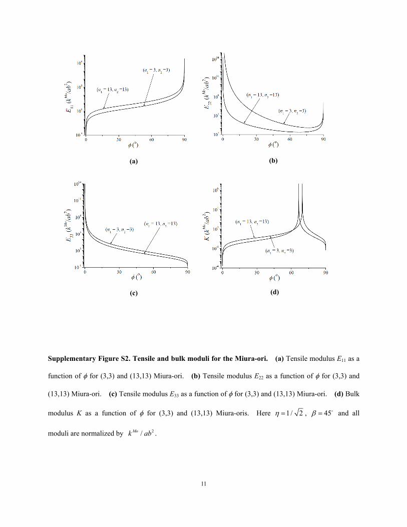
Range of Tensile and Bulk Modulus
Given that [ ]1 3,n ∈ ∞ , [ ]2 3,n ∈ ∞ , and 0 ,2φ β ∈ , [ ]11 0,E ∈ ∞ with 0 for the completely
collapsed state ( 0φ = ) and ∞ for the planar state ( 2φ β= ), [ ]33 0,E ∈ ∞ with 0 for the planar state
( 2φ β= ) and ∞ for the completely collapsed state ( 0φ = ). E22 varies from a finite positive value
(depending on n1, n2, and φ) to ∞ at both the planar and completely collapsed states. Figures S2a-c show
the tensile moduli 11E , 22E , and 33E normalized by 2/Mok ab as a function of φ for a few
representative n1 and n2, and 1 / 2η = , 45β = . Above discussed trends are observed.
Now we study the bulk modulus using Eq. (S7). Since some extreme values (e.g., 0, ∞, and −∞ )
present in either tensile moduli or Poisson's ratios, it is interesting to study the extreme values of K. At
0φ → , 21 31
11
1Eν ν− −
→∞ , 12 32
22
1 0Eν ν− −
→ , and 13 23
33
1 0Eν ν− −
→ , thus the bulk modulus 0K → .
At 2φ β→ , 21 31
11
1 0Eν ν− −
→ , 12 32
22
1 0Eν ν− −
→ , and 13 23
33
1Eν ν− −
→∞ , thus the bulk modulus
0K → . Another interesting point is at a particular state (φ) for the prescribed n1, n2 and β, the right
hand of Eq. (S7) vanishes, which provides an infinity bulk modulus. The vanishing of the right hand of
Eq. (S7) is determined by the numerators, specifically 21 311 ν ν− − , 12 321 ν ν− − , and 13 231 ν ν− − , and
again the condition of vanishing these three terms is given by their numerators. Based on Eq. (4) in the
main text and Eq. (S1), the numerators of 21 311 ν ν− − , 12 321 ν ν− − , and 13 231 ν ν− − happen to be
identical,
( ) ( )( )
( ) ( )( ) ( )
6 4 2
2 3 32 2
2cos 2 cos 2 1 cos
1 cos 2 cos cos 2 1 cosn n
φ φ β
η φ β β η β
− +
+ − + − −. (S17)
The vanishing of the expression (S17) provides a particular state of folding characterized by the angle φ
and dependent on n2 to reach an infinity bulk modulus. Figure S2d shows the bulk modulus K
8
normalized by 2/Mok ab as a function of φ for a few representative n1 and n2, and 1 / 2η = , 45β = ,
where the signature of changing from 0 to ∞ and then 0 is represented.
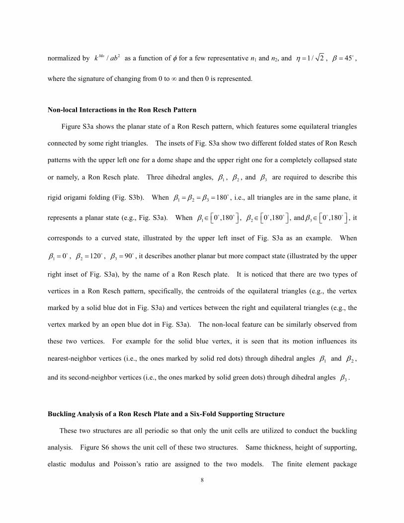
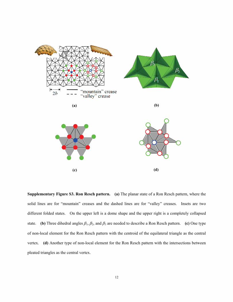
Non-local Interactions in the Ron Resch Pattern
Figure S3a shows the planar state of a Ron Resch pattern, which features some equilateral triangles
connected by some right triangles. The insets of Fig. S3a show two different folded states of Ron Resch
patterns with the upper left one for a dome shape and the upper right one for a completely collapsed state
or namely, a Ron Resch plate. Three dihedral angles, 1β , 2β , and 3β are required to describe this
rigid origami folding (Fig. S3b). When 1 2 3 180β β β= = = , i.e., all triangles are in the same plane, it
represents a planar state (e.g., Fig. S3a). When 1 0 ,180β ∈ , 2 0 ,180β ∈
, and 3 0 ,180β ∈ , it
corresponds to a curved state, illustrated by the upper left inset of Fig. S3a as an example. When
1 0β = , 2 120β = , 3 90β = , it describes another planar but more compact state (illustrated by the upper
right inset of Fig. S3a), by the name of a Ron Resch plate. It is noticed that there are two types of
vertices in a Ron Resch pattern, specifically, the centroids of the equilateral triangles (e.g., the vertex
marked by a solid blue dot in Fig. S3a) and vertices between the right and equilateral triangles (e.g., the
vertex marked by an open blue dot in Fig. S3a). The non-local feature can be similarly observed from
these two vertices. For example for the solid blue vertex, it is seen that its motion influences its
nearest-neighbor vertices (i.e., the ones marked by solid red dots) through dihedral angles 1β and 2β ,
and its second-neighbor vertices (i.e., the ones marked by solid green dots) through dihedral angles 3β .
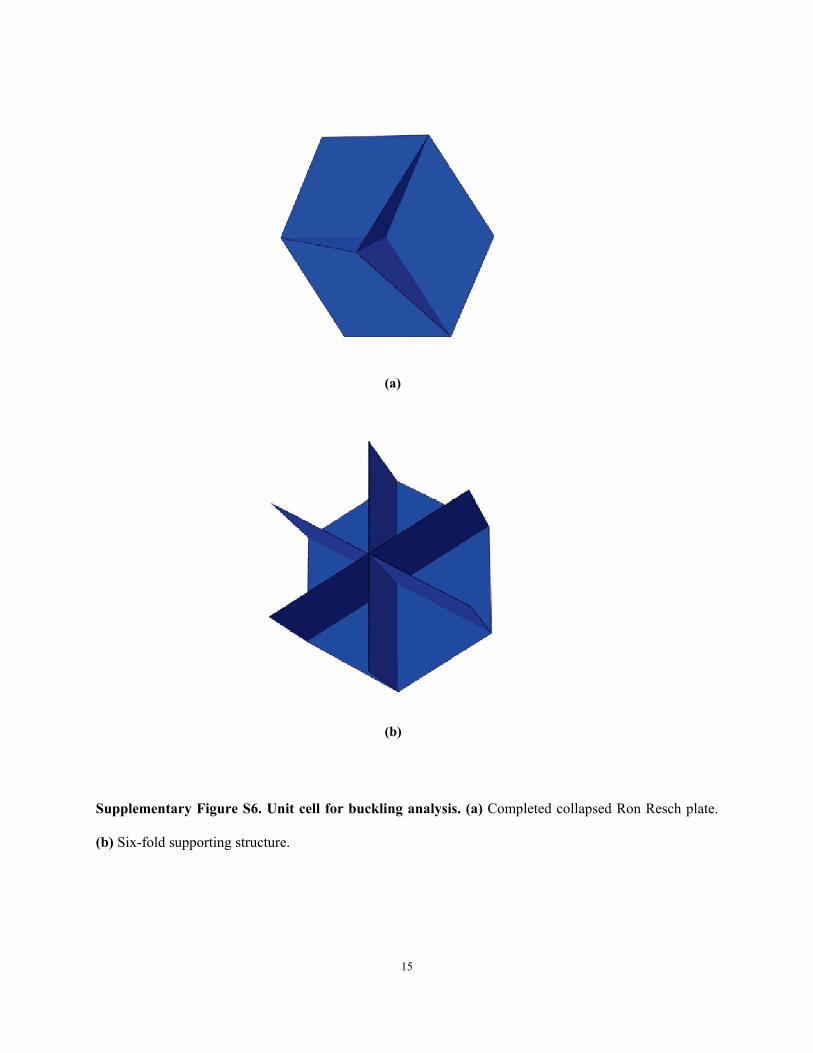
Buckling Analysis of a Ron Resch Plate and a Six-Fold Supporting Structure
These two structures are all periodic so that only the unit cells are utilized to conduct the buckling
analysis. Figure S6 shows the unit cell of these two structures. Same thickness, height of supporting,
elastic modulus and Poisson’s ratio are assigned to the two models. The finite element package
9
ABAQUS is used, where the eigenvalues of the different modes can be calculated by using the built-in
buckling module. Critical load then can be obtained by using
th thi i
crP Pλ= (S18)
where thi
crP is the critical load for the ith mode, P is the infinitesimal load applied in the simulation,
thiλ is the ith eigenvalue. For the Ron Resch plate, 284,258 R3 (3-node triangular shell) elements are
used, with the fixed displacement boundary conditions along the in-plane directions of the plate and the
spike. Contact at the spike between the ground plane and the Ron Resch plate is considered. A very
small concentrated load is applied at the centroid of the plate. For the six-fold supporting structure,
249,268 S4 (4-node doubly curved shell) elements are used. Same boundary conditions and loads are
applied. The cross-sectional properties and material properties of these two structures are the same.
Here only the first buckling mode is concerned. The buckling analysis shows that the critical load for
the Ron Resch plate is 57% higher than that for the six-fold supporting structure.
10
Figures
Supplementary Figure S1. Geometry characteristics of Miura-ori. (a) Change of size W. Here the
change rate of W’s two terms with respective to φ is also shown. (b) Contour plot of out-of-plane
Poisson's ratio ν13 as a function of φ and β. (c) Contour plot of out-of-plane Poisson's ratio ν23 as a
function of φ and β.
(a)
(b) (c)
11
Supplementary Figure S2. Tensile and bulk moduli for the Miura-ori. (a) Tensile modulus E11 as a
function of φ for (3,3) and (13,13) Miura-ori. (b) Tensile modulus E22 as a function of φ for (3,3) and
(13,13) Miura-ori. (c) Tensile modulus E33 as a function of φ for (3,3) and (13,13) Miura-ori. (d) Bulk
modulus K as a function of φ for (3,3) and (13,13) Miura-oris. Here 1 / 2η = , 45β = and all
moduli are normalized by 2/Mok ab .
(a) (b)
(c) (d)
12
Supplementary Figure S3. Ron Resch pattern. (a) The planar state of a Ron Resch pattern, where the
solid lines are for “mountain” creases and the dashed lines are for “valley” creases. Insets are two
different folded states. On the upper left is a dome shape and the upper right is a completely collapsed
state. (b) Three dihedral angles β1, β2, and β3 are needed to describe a Ron Resch pattern. (c) One type
of non-local element for the Ron Resch pattern with the centroid of the equilateral triangle as the central
vertex. (d) Another type of non-local element for the Ron Resch pattern with the intersections between
pleated triangles as the central vertex.
(a) (b)
(c) (d)
13
Supplementary Figure S4. Shear deformation of a Miura-ori. Deformation of a (13,13) Miura-ori
under shear loading along the negative x1 direction. It is observed that the opposite relationship between
shear loading and shear deformation.
14
Supplementary Figure S5. Histograms of the three dihedral angles (a) 1β , (b) 2β , and (c) 3β for
three Ron Resch patterns, namely a Ron Resch dome, a tube and a stingray.
(a)
(b)
(c)
15
Supplementary Figure S6. Unit cell for buckling analysis. (a) Completed collapsed Ron Resch plate.
(b) Six-fold supporting structure.
(a)
(b)
16
References
1. B. Liu, Y. Huang, H. Jiang, S. Qu, K. C. Hwang, Computer Methods in Applied Mechanics and Engineering 193, 1849 (2004).
2. B. Liu et al., Physical Review B 72, 8 (Jul, 2005).
View publication statsView publication stats