origami spyglass design feasibility for economic and ... spyglass... · origami spyglass design...
TRANSCRIPT

Origami Spyglass Design Feasibility for Economic and
Educational Advancement in Lesoit, Tanzania
Dominic McGonegal, Dwayne Codding, Badah Badah,
Mohammad Alzaid, Mosab Alfailakawi
EGR 476C – Engineering Design
Instructor: Dianne McDonnell
Ashwija Reddy Korenda
Department of Mechanical Engineering
Northern Arizona University
Flagstaff, AZ 86011
2
Executive Summary:
The focus of this project is to present the community of Lesoit, Tanzania with a product
whose main function is to help facilitate economic and educational development within the
community. This product is to be an origami spyglass incorporated into an educational booklet
which focuses on wildlife education. The spyglass is intended to be assembled from a single pre-
cut page of the booklet and folded into the three-dimensional scope to be used for viewing the
local wildlife that is described within the booklet. A lesson plan will also be created in addition
to the booklets to ensure more of a mentorship-type environment, which has been shown to
increase student interest and reduce student dropout rates. This design is to be constructed in
such a way that the women in the village of Lesoit will be able to manufacture these booklets and
market them to nearby other communities boost their local economy. The design is also intended
to be modified for tourism applications as well, since recent studies have shown that the tourist
population and spending has increased by 122% and $27.5 million respectively.
The manufacturing process of these booklet will involve a laser cutting printer to speed
the process of cutting pages for the housing of the spyglass, as well as a clear-resin 3D printer
that will be used to develop lenses for the spyglass. These production options have proven to be
the simplest, most cost effective, and versatile products compared to processes which would use
recycled materials and plastic/glass molding techniques. To meet the power need of the
manufacturing machinery, the Maasai community will need to set up a small workspace in the
nearby city of Arusha. After production is completed, sets may be brought back to the village to
assemble and distribute the booklets.
After initial prototype testing, the Tri-Hex design is the best rigid structure so far that
offers several contact points for lens attachment. This design is constructed from a single sheet of
paper with minimal cuts, meaning the space between the lenses has minimal interference from
ambient light. Future plans for mechanical testing will determine if the product needs to be
reinforced through supplemental supports like an internal truss system.
Future plans for the project will include coordinating with other school departments to
allow for outsourcing of specialized tasks such as graphic design, business planning, and lesson
plan design. Testing and redesign of the spyglass will also be conducted in future iterations of
this product.

3
Acknowledgements:
● Dr. Dianne McDonnell
● Ashwija Korenda
● Evalyne Long’arwa
● Dr. Christopher Mann
● Todd Rossman
● Jon Helleson
● Sharna Beahm

4
1 TABLE OF CONTENTS
2 Background .............................................................................................................................. 6
2.1 Technical .......................................................................................................................... 6
2.2 Cultural ............................................................................................................................. 6
2.3 Problem Statement and Objectives .................................................................................. 7
3 Spyglass Design ....................................................................................................................... 8
3.1 Options for Manufacturing ............................................................................................... 8
3.2 Design............................................................................................................................... 9
3.2.1 Educational Booklet .................................................................................................. 9
3.2.2 Paper Housing ........................................................................................................... 9
3.2.3 3D Printed Lenses ..................................................................................................... 9
4 Lens Calculations .................................................................................................................. 10
5 Housing Designs and Prototyping ......................................................................................... 12
5.1 Housing Designs ............................................................................................................ 12
5.2 Fastening Designs .......................................................................................................... 14
5.3 Design Selection for Prototype Phase ............................................................................ 15
5.4 Prototyping ..................................................................................................................... 15
5.4.1 Material Performance Comparison ......................................................................... 19
5.4.2 Fastener Design and Performance .......................................................................... 20
5.4.3 Results and Recommendations ............................................................................... 21
6 Business Model...................................................................................................................... 21
6.1 Operation Guide ............................................................................................................. 21
6.2 SWOT Analysis.............................................................................................................. 22
7 Recommendations ................................................................................................................. 23
8 Future Work ........................................................................................................................... 23
9 Conclusion ............................................................................................................................. 28
10 References .......................................................................................................................... 29
11 Appendices ......................................................................................................................... 29

5
List of Figures:
List of Tables:

6
2 BACKGROUND
2.1 TECHNICAL FIGURE 1: Foldscope Microscope Design
A research team at Stanford University had designed the Foldscope, a low cost, durable
design for a microscope that could be implemented in third world countries. The product made
education and real-world health applications to be both affordable and attainable in communities
that otherwise could not afford attaining and maintaining lab equipment [FOLDSCOPE].
The foldscope design inspired this capstone project, where a low cost, optics education
tool could be created through simple assemblies of paper products. However, instead of focusing
solely on educational benefits for the community, our project aims to design an easy-to-
manufacture product that could be assembled in a third world country in order to facilitate
economic growth for the community.
The original foldscope design is a microscope that is made out of paper and small lenses
that can be assembled in multiple configurations depending on the application. Similar to the
foldscope, we would apply elements of optics to create an education tool, though we would
pursue a spyglass design instead of a microscope. Our product will be designed to be assembled
from pre-cut paper housing designs that can be folded into a rigid body with secured lenses.
In addition to creating a paper spyglass, the project plan is to incorporate the spyglass into
an educational booklet focused on wildlife education in order to reduce dropout rates and
increase interest in the region. If the village of Lesoit would like more economic opportunities,
the educational design could be adapted to more lucrative applications like tourism. The
foldscope design is the basis of our project, but we are taking the idea and applying it to a
different field of education while also allowing the involved communities to build income by
marketing this product.
2.2 CULTURAL
The Maasai people in Tanzania have rural communities such as Lesoit Village where
education and professional opportunities are limited for women. These limitations exist through
several barriers within the culture, geography, and economy in these communities. These barriers
prevent female students from pursuing higher education and professional opportunities for fields
in Science, Technology, Engineering, and Mathematics (STEM). There is a need for creating
accessible education for young children in rural communities and providing an improved outlook
for Maasai women in the job market.
Maasai culture in Tanzania is driven by gender roles that place limitations on the education
and professional development of women. These limitations often take the form of expectations
such as chores and financial burdens that are exclusive to women in most households. This

7
cultural outlook has an impact on young Maasai girls as households are less likely to invest in
schooling or training for females [A. ELLIS].
Household chores for Maasai women that consume large amounts of time and energy can
range from gathering firewood and water to processing food crops and taking care of the sick.
These responsibilities are barriers for business oriented women that are seeking to earn a living
wage. These barriers are even harsher when there are children involved as opportunities for
daycare are expensive.
Any women that manage to earn a wage tend to earn 3.5 times less than men, regardless of
qualifications. In spite of this, the bulk of household expenses are proportionally affected by how
much is earned by women in a household [A. ELLIS].
Common factors that prevent young students from pursuing opportunities in schooling and
training tend to be related to economics and geography. Many rural communities have a single
school available which can be physically distant for some families. This distance can serve as a
deterrent for children that walk to school. Additionally, low income households face difficult
financial decisions that impact access to education. Expenses related to education create a strain
for these families. Children sometimes drop out from school to cut these expenses while being
put to work to help support their families [ALARMING DROPOUT RATES].
These geographic and economic barriers create a need for affordable education that can be
accessible to low income households in rural communities. This need is emphasized for female
students as cultural norms reduce opportunities for young girls and have professional impacts for
Maasai women.
2.3 PROBLEM STATEMENT AND OBJECTIVES
The education system in Tanzania should prepare students for technical careers in STEM,
regardless of gender or economic background. Additionally, the women of Tanzania should have
professional opportunities to earn income in a workplace that is compatible with cultural norms
in their community. Designs for academic tools should offer affordable accessibility to education
beyond the existing opportunities found in rural schools. Designs should also take advantage of
the Tourism industry to offer new products and souvenirs that would impact the local economy.
However, the current education system faces dropout rates throughout all levels of primary
school, going as high as a 7% drop out rate for the graduating 5th grade class of 2009 [2]. The
cultural norms currently place a higher value in educating young boys instead of girls as grown
women are defined by household responsibilities instead of professional development. Current
job markets offer women work in agriculture and unpaid labor with a higher frequency while
men have better opportunities in pursuing manufacturing and other technical jobs [1]. These
current trends show that less resources are invested in a viable workforce than can be found in
Maasai women.
By introducing manufacturing technologies such as 3D printing and a laser cutting printer,
new job opportunities can be introduced for rural families. Sustainable business opportunities

8
can then rely on these manufacturing technologies as well as the local Tourism attractions.
Proposed designs for new academic tools can then be formed locally, offering better costs to
schools and rural families. These solutions can improve educational resources, reduce dropout
rates, and increase career opportunities for women.
3 SPYGLASS DESIGN
3.1 OPTIONS FOR MANUFACTURING
Many different materials and manufacturing processes were researched to determine the
best methods for both lens and housing production. Lens molding was the first manufacturing
process to be ruled out during the research phase due to the amount of high precision post-
processing that had to be done to obtain usable lenses [CITE TEKRON?]. Recycled materials
were also the first to be ruled out because of the number of contaminants in both recycled glass
and plastics [5 (from GP)]. Since these materials and processes were not usable for the spyglass
application, research focused on the possibility of 3D printing lenses which led to the discovery
of the Form 1+ printer. This printer uses a specific laser printing process that allows for up to 4
times the resolution of heated filament 3D printers and also has the capability of printing using a
clear, acrylic resin [FORMLABS].
Figure 2: Form 1+ 3D Printer
As of now, this 3D printer is the best option for lens manufacturing, although the village
of Lesoit does not have electrical energy available, so the printer would have to be used in a
small workspace in the nearby city Arusha. The housing production research started by looking
at the foldscope production equipment, which was an industrial sized laser cutting printer. Since
this project is focused more around creating a pilot business and up-scaling in the future, the
industrial capabilities were unnecessary. Looking toward more personal laser cutting printers, the
Glowforge printer was found and was determined to be the best option due to its size, price, ease
of use, and versatility.
Figure 3: Glowforge Laser Cutting Printer
The Glowforge has the capability of cutting through other materials like leather which
would also allow the local women to use this equipment to produce more retail products in the
future [CITE GLOWFORGE]. After researching other local production methods in Tanzania, it
was determined that the Form 1+ and the Glowforge printers are the most feasible approach at
this point.

9
3.2 DESIGN
3.2.1 Educational Booklet
As mentioned earlier, the spyglass design this project is focused around is to be
contained in an educational booklet based on local wildlife. This booklet will house
information on a variety of wildlife that is known to inhabit the regions applicable to the
region where the booklets are being produced. It is planned that the engineering
department will partner with NAU art and education departments to develop this booklet
and provide meaningful information as well as interesting and accurate artistic
representations of the animals discussed. The spyglass is to be installed in the back of the
booklet, where the housing can be removed from a single page and one of the final pages
is cut to safely carry the 3D printed lenses.
3.2.2 Paper Housing
The main function of the spyglass housing is to provide a sturdy, durable structure
for the 3D printed lenses. The housing is also to be cut from a single page of the booklet
and perforated to make the intended folds easy to reproduce by any child 8 years of age
or older. These criteria are applied to the housing prototype testing, outlined later in the
report, in which a final design is chosen based on its performance in these fields.
3.2.3 3D Printed Lenses
The lenses are the most crucial part of the spyglass assembly simply because they
are what provides the magnification needed to examine wildlife from a distance. The
proposed magnification of the spyglass is to be between 10 and 20 times magnification.
This range will allow for the determination of the focal point of the lenses and provide
the dimensions required to run optical simulations in the Zmax program and test different
magnification values.

10
4 LENS CALCULATIONS
The team chose the Galilean telescope because it is easy to construct and build, so the kids
could build it by their own. Because the focal point is going to be the eye itself, it will help us
with the calculation.
Figure 1: Galilean telescope [1]
Galilean telescope has two lenses one is convex which is going to be in the front of the
telescope, and the other one is concave, it is going to in the back of the telescope as shown
in figure 1 above[1]. The lens sets on the either side of the telescope such that the focal point of
the eyepiece lens is the same as the focal point for the objective. The Galilean telescope was
determined as the first telescope can be expand the range of magnification, and it has more the
3x magnification. A thing considered to be a problem or a disadvantage of the Galilean telescope
that it has a small field of view [2].
In order to design a lens we need to assume some value, the team came up with some
values as the length of the telescope and magnification.
The team used three equations in order the design the lens theoretically [3,4].
1/f=(n-1)(1/r1-1/r2)
This equation is the focal length equation, and it is only applied for one lens, where
f : The focal length
n : The material refractive index.
r1 : The outer radius of curvature.
r2 : The inner radius of curvature.
For the material refractive index for photopolymer which is the material provided from
the 3D printer.
L= fo+fe
This the length of telescope equation, where

11
L : The length of the telescope.
fo : The focal length of the objective lens.
fe : The focal length of the eyepiece lens.
This equation allows us to determine the focal length of the objective and the focal lens
of the eyepiece lens.
M= -fo/fe
This equation is the magnification equation, M represents the magnification, and this
equation allows us too to determine the focal length of the objective lens and the focal
length of the eyepiece lens.
The table below shows the values the team chose for the length of the telescope and for the
magnification, and it shows the values after the team did the calculations.
Table 1: values predicted and calculated for designing the lens
Lens Properties Current values
Material Refractive Index (n) 1.514 [5]
Length of Spyglass (L) 15 cm (chosen)
Magnification (M) 10x (chosen)
Objective Lens Focal Length (Fo) 16.67 cm
Eyepiece Lens Focal Length (Fe) -1.67 cm

12
5 HOUSING DESIGNS AND PROTOTYPING
5.1 HOUSING DESIGNS Square Cross-Section
This design was created with the intention of keeping the assembly and blueprint design
as simple as possible. The design’s simplicity would allow for young students to assemble the
spyglass with minimal or no help from the class teacher. It would also help the women who are
responsible for manufacturing to learn how it was designed and facilitate the creation of their
own designs/modifications for the spyglass product.
As seen in the figure below, the housing is a simple, tapered rectangular prism. This
shape requires only three main folds and can be secured using paper tabs, which are shown in the
Solidworks rendering of the housing.
Figure 1: Square Cross-Section Solidworks Model
Tri-Hex Cross-Section
The ‘Tri-Hex’ design focuses more on the structural integrity of the housing more than
simplicity. Having a triangular prism for the exterior and a hexagonal interior creates a type of
truss system which would resist deformation or crushing and provide better lens protection.
Unlike the square cross-section design, this design will require many more fastening points in
order to keep the hexagonal interior from shifting inside the triangular body and provide the
needed structural support.
Theoretically, any of the fastening methods covered in the next section could be used to
secure this housing. The method that appears to be the simplest however, is the folding tab
method which was designed specifically for this housing model. This method would require a

13
total of six tabs, three for each end of the spyglass, and would allow for a stable link between the
two cross-sections without obstructing the view inside of the hexagonal lens housing.
Figure 2: Tri-Hex Cross-Section Solidworks Model
Accordion Design
As seen from the next figure, this design proved to be a rough concept of a possible
design direction. The main consideration for this concept was the ability to adjust the distance
between the lenses to modify the focus of the image. It was decided that the assembly would be
too difficult to carry on with, although the idea of focus compensation is important to this project
and will need to be address when the final prototype is developed.
Figure 3: Accordion Concept Physical Model

14
Circular Cross-Section
This design was the only of the four physical models to require the use of tape to achieve
the desired shape, although, like the accordion concept, this also addressed the possibility of
changing distance between the lenses to adjust focus. Because the circular shape does not
provide an easy method for securing lenses to the body, this design was excluded from the
candidates to move on to the prototyping phase.
Figure 4: Circular Cross-Section Design Physical Model
5.2 FASTENING DESIGNS Single Tab
The single tab method is the simplest of the four methods that were introduced. The
method uses a single tab which runs the length of housing and effectively secures only the ends
of the housing. The disadvantage to this design is that the housing will be free to warp and bend
throughout the mid-section due to a lack of contact points. This method would be ideal with
extremely rigid paper, but the multi-tab design solves this problem by using many smaller tabs to
create a higher number of contact points.
Multi-Tab
The multi-tab method uses the same concept as the single tab design and applies the
technique with many smaller tabs along the fastening edge. This method creates a strong edge
with many contact points which prevent bending or warping along the distance of the housing.
This fastening method is expected to be used in the final product because of its simplicity and
functionality.
Hook-Tab
Hook-tabs are also a good fastening option because they provide the most contact area
between the tab and the housing, better supporting the fastening corner. The disadvantage to this
method is that there is a large gap that allows for light to enter through the fastening edge which
could obscure the view of the user.
15
Folding Tab
The folding tabs were introduced after the prototyping phase, but have been added here
because they are theoretically the most viable option for securing the Tri-Hex design easily.
These tabs would protrude from each end of the hexagonal body along the axial planes which are
in contact with the triangular planes. They are designed to fold at each end of the housing and
securing the hexagonal body to the triangular with tabs that will be inserted into the small
triangular spaces in each corner. This allows for rigid body using no adhesives and the tabs do
not penetrate the interior lens housing so there is not view obstruction.
5.3 DESIGN SELECTION FOR PROTOTYPE PHASE The final designs chosen for prototyping are the square and Tri-Hex cross-section designs
based on their simplicity and structural integrity, respectively. These designs will also be tested
using the multi-tab and folding tab techniques to determine the difference in difficulty to
assemble. Of these two designs, the Tri-Hex design is expected to be the final product because it
is the most structurally sound and the fastening method does not penetrate the portion of the
housing containing the lenses. If simplicity is the ultimate goal for the product then the square
cross-section design is expected to be the optimal choice because of the ease of design and
assembly which also benefit the students as well as the manufacturers.
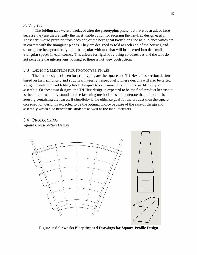
5.4 PROTOTYPING Square Cross-Section Design
Figure 1: Solidworks Blueprint and Drawings for Square-Profile Design

16
The square-cross section design focuses on making a simple, easy to assemble housing
whose blueprint can fit on a single page. As shown above, the housing is a tapered, rectangular
prism based around the dimensions of the lenses, which are 2cm and 4cm in diameter, as well as
a chosen housing length of 10cm.
Figure 2: Square Cross-Section Construction Prototypes
The physical model of this design proved that the housing construction is the simpler of
the two designs tested. The design requires only 3 main folds and fastens along a single edge,
which made for quick, simple assembly. A main drawback to this assembly, and possible future
problem for the project, is that any fastening method used for this design penetrates the viewing
space and could obstruct the light moving through the telescope.
Due to the design’s simplicity, the housing is not a rigid body without the lenses acting as
supports inside the assembly. The housing alone is simple to collapse and will fold flat along the
two folds which are opposite each other. A proposed idea to fix this design in the future is to
create some sort of 3D printed support structure to fit inside the housing to increase rigidity, as
simply using a thicker paper will not solve the problem.
Much of this design’s durability is determined directly by the paper used in construction.
The structure is easy to bend and manipulate, allowing for the housing to deform even when the
lenses are inserted, meaning dropping the housing could seriously impair its function. Using
thicker paper would help to prevent this issue, but this design is relatively fragile compared to
the Tri-Hex.

17
‘Tri-Hex’ Design
Figure 3: Solidworks Blueprint and Drawings for ‘Tri-Hex’ Design
The Tri-Hex design is the more robust design out of the two that were tested. As shown
above, the exterior of the housing is a tapered, triangular prism, which provides better rigidity to
the overall structure. Using the triangular profile prevents the assembly from folding flat when
crushed, like the rectangular design, offering better lens protection. A hexagonal cylinder is used
to reinforce the triangular exoskeleton and allow more points of contact to secure the lenses
within the housing.

18
Figure 4: Tri-Hex Construction Prototypes
The physical prototype of the Tri-Hex method revealed that this design assembly is
slightly more complicated than the square design, simply because of the increased number of
folds and fastening points. With the fastening methods proposed, there is no single step in the
assembly that is more complicated than those of the square design.. Using a laser printer to create
perforations along fold lines is expected to keep the assembly process simple and comparable to
the square method and minimize any confusion that the added steps may create.
Although this design is still simple, it has proven to be a much more rigid structure than
that of the square prototype. The hexagonal shape enclosed within the triangular exterior acts as
a truss system, preventing the triangle’s faces from collapsing. The triangular shape also secures
the hexagonal interior and prevents any deformation. Of the two designs, this is the most
promising for structure. Using this design would eliminate the need to investigate the use of 3D
printed supports, saving on material costs.
The design durability depends on the type of paper used, but the construction allows for a
substantial amount of torsional and crushing forces without permanently damaging the housing.
The triangular exterior also acts as a safety measure when the scope is dropped, the design
allows for the housing to be damaged without as high a risk of lens damage. Using thicker paper
for the housing as well as adjusting the cuts of the triangular exterior may allow for greater lens
security, increasing overall durability.

19
5.4.1 Material Performance Comparison
Table2: Material Comparison
Paper
Type
Pricing [1] Weight
(per ream)
Stiffness Durability Construction
Difficulty
Printing
paper
$10.29 20-32 lb Low Low Medium
67lb
Weight
$12.99 67 lb Medium Medium Low
110lb
Weight
$14.19 110 lb Medium Medium Low
As shown in the table above, the three construction materials that were tested were copy
paper, 67lb weight paper, and 110lb weight paper. Of the three tested, the copy paper was the
weakest material, while the 67lb and 110lb papers were nearly identical. It was observed that the
110lb paper held a better fold than that of the 67lb paper, which is the main differentiating factor
between the two. Although, since the two weighted papers are nearly identical in performance,
the 67lb paper would be the most feasible option due to its price per ream. If the housing is
required to be stronger in the future, it is recommended that the paper weight be more than
doubled to exhibit any noticeable difference. At this time, it has been decided that the
mechanical and elementary class testing done next semester will be done with 67lb paper.

20
5.4.2 Fastener Design and Performance
Single Tab
The single tab method was the simplest of the three fastening designs that were tested
during the prototyping phase, although it offered little structural benefit. Due to the fact that the
only two contact points between the tab and the connecting edge of the housing were at each end
of the assembly, the fastener edge of the housing could warp easily. It was determined that more
contact points must be needed to maintain a strong fastening edge, which led to the design of the
multi-tab method below.
FIgure 5: Single Tab Blueprint
Multi-Tab
The multi-tab method is currently the most promising fastening method. The increased
number of contact points creates a strong fastening edge that is still simple to assemble. Of the
three methods tested, this method performed the best and is expected to be used in the assembly
of the final product with some minor changes to the tabs to greater simplify the construction
process.
Figure 6: Multi-Tab Blueprint

21
Hook Tabs
Hook tabs are a possible solution for the fastening of the hexagonal and triangular bodies
in the Tri-Hex design, but are not practical for the square design compared to the multi-tab
method. When tested with the square design, because the cuts on the fastening edge of the
housing have to be offset to the hooks, there were large openings along the fastening edge which
would allow for light to penetrate into the lens space. Since the lenses we will be creating will
not be perfectly clear, this could create glare and obstruct the viewer’s vision. Because the
hexagon assembly is completely contained within the triangular exterior however, this could be
used to fasten parts of the Tri-Hex housing if it proves to be more feasible for the final assembly.
Figure 7: Hook Tab Blueprint
5.4.3 Results and Recommendations Of the two main designs tested, the Tri-Hex design is recommended as the final design to
carry through to next semester’s mechanical testing. This decision is based on the fact that the
Tri-Hex model was much more structurally sound and offered a greater durability due to its
structure. It is expected that the fastening points on the Tri-Hex assembly will all be multi-tab
connections, however the Tri-Hex model has the capability of utilizing the hook method if that is
determined to be the best solution. Finally, if the mechanical testing proves that the housing is
not strong enough to serve an adequate lifetime, then a stronger paper must be selected and
tested as well and should be approximately 200lb paper for a noticeable difference in
performance.
6 BUSINESS MODEL
6.1 OPERATION GUIDE The expected labor force for this business would include a couple people operating the
manufacturing machinery and the rest accommodating for post processing and transportation
needs. A single person should be able to operate the 3D printer at any given part of the day and
at least one person would be needed for the laser cutting printer. The bulk of the labor force

22
would likely be assigned to polishing printed lenses and assembling the educational booklets.
Such a labor force would be estimated based on the amount of printing machines attained. For
every 3D printer, we would expect 2 to 3 employees would be needed for the polishing process.
Similarly, for every laser cutting printer, we would expect 2 to 3 employees would be needed to
assemble the booklets. This booklet assembly would include the binding of pages as well as the
inclusion of polished lenses and pop out parts for the foldscope. Labor force devoted to shipping
would depend on the resulting production volume, the amount of demand, and the frequency of
travel.
6.2 SWOT ANALYSIS Table #: SWOT analysis
I
N
T
E
R
N
A
L
STRENGTHS
It’s dependent project that pay itself.
Creation of new jobs.
Economic growth in rural
communities.
Unique technology in the area (3D
printer) offers products that can’t be
easily replicated.
WEAKNESSES
Limited manufacturing
technologies impact production
volume.
Retrieving new materials are
subject to shipping and handling
expenses.
High need for training the people
how to build the foldscope
CAD software training needed
before printer can be utilized
beyond the creation of lenses for
the foldscope.
E
X
T
E
R
N
A
L
OPPORTUNITIES
Local Tourism offers a market to sell
new products to.
Untapped job force of Maasai women
that are seeking additional income.
Valuable assets are provided at the
expense of NAU, not the business.
Initial designs provided by NAU
engineering students.
Supplemental products like the
educational booklet will be designed
by NAU students from specialized
departments.
THREATS
Weak economy in rural
communities limits the market.
Cultural norms value having
women in the household instead of
workforce.
Resources limited to Arusha and
surrounding communities.
Transportation is heavily dependant
on the existing infrastructure.

23
7 RECOMMENDATIONS
Our current recommendation for the design project is to use the Tri-Hex design to build the
spyglass housing. This design has a rigid triangular structure and will have the advantage of
being an easy to assemble product. Unlike other designs, the Tri-Hex design meets requirements
of securing space between the lenses that doesn’t allow for ambient light.
8 FUTURE WORK
For manufacturing in Tanzania, there will be a need for a workshop to manufacture the
booklets. This workspace will provide a safe environment for the workers and prevent any kind
of theft that could affect the production and job security for this product. Future coordination
with business students will help us design an ideal work environment that will offer high
productivity and ideal working conditions for the female workforce. We expect to implement a
product tracking and reporting system to prevent any type of complacency in the work.
For next semester, we expect to further develop the lens dimensions, which in turn determine the
housing dimensions. Our priority for next semester is to finalize these calculations. Further tasks
will include design for the educational booklet through outsourcing with complimentary
departments at NAU.

24
8.1 FALL SCHEDULE
Key Tasks Allocated Time
(days)
Deadline
Team
Member
Assignment
Interdepartmental Outreach MILESTONE Aug 30th -
Education (Lesson Plan): Make an
appointment with the education
department to discuss the project and
lessons we want to use in it
5
Badah
Graphic Design (Housing): Contact the
graphic design department to discuss
the housing design
5
Dominic
Business (Business Plan): Contact the
business department to discuss the
business plan
5
Mohammad
DeMiguel (Schedule Testing dates):
Contact the teachers from the school
department to discuss the design
testing
5
Dwayne
Prototype 1 MILESTONE Sept 6th -
Paper Housing Design: Finish the
housing design prototype
3
Badah
Laser Cutting (3rd party): Buy the
cutting printer from Glowforge
2
Mosab
Assembly Testing at DeMiguel: Test
the prototype in the local school
2
Dwayne
Lens Calculations: Finalize the lens
calculations and dimensions
Dominic
Presentation 1 MILESTONE Sept 20th -
Design Summary: Summarize the
design and be ready to present it
2
Mosab
Environmental Analysis: An
environmental analysis is to be done
for the product and presented
3
Dominic

25
DeMiguel Results: Present the
prototype testing results from the local
school
6
Dwayne
Testing (Plan Update): The prototype
design testing results
5
Badah
Outreach Summary 2
Mohammad
Paper 1 (Prototyping) MILESTONE Sept 27th -
Load Bearing testing: Report about the
load testing results
2
Mohammad
Twisting Testing: Report about the
twisting testing
2
Mosab
Bending Testing: Report about the
bending testing
2
Dominic
Sweat, Dirt, Water (Nature Testing):
Report about the nature testing
4
Badah
Prototype 2 MILESTONE Oct 11th -
Paper Housing Redesign: Fix what was
wrong in Prototype 1
4
Dominic
Durability Testing at DeMiguel: Test
prototype 2 in the local school after
adding the improvements
Badah
SolidWorks Lens Design: Create
digital graphic sketch of the lens using
solidworks software to
Dwayne
3D Printer Testing: test the 3D printer
for the lenses
6
Mohammad
Presentation 2 MILESTONE Oct 18th -
Prototype Testing Results: (test the
prototype and make sure its work.
1
Mosab
DeMiguel Results: let the children test
the project.
1
Dwayne

26
Lesson Plan Update: finishing the
lessons that we want to include in the
booklet
2
Badah
Graphic Design Update: get the design
for the booklet done from one of the
students in that department.
1
Dominic
Business Plan Update: Update the
business plan and insert it into the
powerpoint
1
Mohammad
Paper 2 (Schedule of Materials) MILESTONE Oct 25th -
Material Costs: get the cost for the
materials for the stable store or online.
4
Mosab
Projected Labor Costs:Research about
the labore cost and mak a table and
options.
4
Dwayne
Installation and Shipping Costs: figure
out the total price with the shipping.
3
Mohammad
Presentation 3 (Practice for final) MILESTONE Nov 15th -
Background and Problem Statement:
doing the introduction for the practice
presentation.
1
Badah
Design Summary (Final): describe the
final design.
1
Dominic
Manufacturing Summary: Present the
manufacturing process
1
Dwayne
Business Model Update: update the
business model and put it in a good
format
1
Mosab
Lesson Plan Summary: summarized
the lesson plan and apply them into the
booklet.
1
Mohammad
Future Recommendations: make a
recommendation for our future project
so people can work on it and improve
it in the future.
1
Badah

27
Final Report MILESTONE Nov 29th -
Design and Test Summary:
summarized the design and write up
the description.
1/2
Dwayne
Final Business Model 1/2
Mosab
Final Economic and Environmental
Analysis
1
Badah
Final Product MILESTONE Dec 1st -
Final Graphic Design Update: take the
final design from one student from that
department.
Dwayne
Laser Cutting (3rd party): work on the
lenses and print them via the 3D
printer.
Mohammad
3D Printing (Final Lenses): print the
lens and get it done for the final
design.
Dominic
Assembly (Scope and Lesson Plan):
make sure everything is good and
work.
Mosab
UGRADS MILESTONE Dec 2nd -
Final Editing of Presentation: format
the final presentation and make it
ready to present.
Dominic

28
9 CONCLUSION
The design of a low cost education tool can be achieved through the addition of laser cutting and
3D printing technology. The selection of the Form 1+ printer is largely based on the high
resolution that is achievable through this technology. The Glowforge laser cutter is beneficial in
cutting down assembly time and offers lucrative opportunities for the community to create
souvenirs from paper and leather products. The final product will consist of an educational
booklet which will contain a precut assembly of a spyglass housing with attachable lenses. This
product will be provided in an alternate format to accommodate the tourism industry as well as
the classroom. Package offers for schools will include a supplemental lesson plan that will
encourage the development of STEM topics through wildlife education. Final housing design is a
Tri-Hex cross-section design until future testing calls for reinforcement or new design
considerations. Future plans will include outsourcing with other school departments for
specialized tasks such as graphic design, business planning, and lesson plan design.

29
10 REFERENCES
LENS CALCULATION REFERENCES
[1]"Refractive Telescopes", Hyperphysics.phy-astr.gsu.edu, 2016. [Online]. Available:
http://hyperphysics.phy-astr.gsu.edu/hbase/geoopt/teles.html. [Accessed: 24- Apr- 2016].
[2]"Making a Galilean Telescope", Galileo.rice.edu, 2016. [Online]. Available:
http://galileo.rice.edu/lib/student_work/astronomy96/mtelescope.html. [Accessed: 06- May-
2016].
[3]"Telescope Equations", Rocketmime.com, 2016. [Online]. Available:
http://www.rocketmime.com/astronomy/Telescope/telescope_eqn.html#Intro. [Accessed: 28-
Apr- 2016].
[4]"Radii of curvature for lenses", YouTube, 2016. [Online]. Available:
https://www.youtube.com/watch?v=vSOdNf0Oh-Q. [Accessed: 28- Apr- 2016].
[5]"Somos® WaterShed XC 11122", Somos, 2015. [Online]. Available:
http://www.dsm.com/content/dam/dsm/somos/en_US/documents/Brand-Status-Sell-
Sheets/English-Letter/Somos%20WaterShed%20XC%2011122%20SS-PDS%20Letter.pdf.
[Accessed: 28- Apr- 2016]. [Accessed: 24- Apr- 2016].
11 APPENDICES