original assembly instructions – english turbocharger ... · turbocharger / a100-m radial...
TRANSCRIPT

Turbocharger / A100-M radialOriginal assembly instructions – English
This document is valid for the A100-M series:
A150-M, A155-M
PurposeThe assembly instructions explain how the ABB turbocharger is fitted to the engine correctly and without any health and safety risks.
Target groupThe assembly instructions are intended for engineers and mechanics responsible for fitting the turbocharger on the engine.
A100-M turbochargerMore power, less fuel
ASSEMBLY INSTRUCTIONS
Turbocharger / A100-M radialOriginal assembly instructions – English
—


Assembly Instructions / A150-M.. - A155-M..Table of contents
© Copyright 2017 ABB. All rights reserved. HZTL455311P0006_EN Revision A November 2017
Assembly Instructions1 Introduction............................................................................................................ 21.1 Purpose of the assembly instructions....................................................................... 21.2 Definition of target group ........................................................................................... 21.3 Symbols, definitions...................................................................................................... 21.4 Definition of warning, caution, note.......................................................................... 31.5 Definition of mandatory signs ................................................................................... 41.6 Definition of pictograms............................................................................................. 4
2 Safety ...................................................................................................................... 52.1 Introduction .................................................................................................................... 52.2 Lifting of loads .............................................................................................................. 62.3 Occupational safety ...................................................................................................... 7
3 Weight and transportation of the turbocharger ............................................. 10
4 Installing the turbocharger.................................................................................. 114.1 Inserting gaskets ......................................................................................................... 114.2 Placing the turbocharger on the bracket ................................................................ 124.3 Fastening the turbocharger with a clamping nut ................................................. 144.4 Connecting the turbocharger.................................................................................... 164.5 Attaching the support ................................................................................................ 16
5 Storage of new turbochargers and spare parts .............................................. 17
6 Further information............................................................................................. 20

Assembly Instructions / A150-M.. - A155-M..1 Introduction / 1.1 Purpose of the assembly instructions
© Copyright 2017 ABB. All rights reserved. HZTL455311P0006_EN Revision A November 2017
1 Introduction
1.1 Purpose of the assembly instructionsThe assembly instructions explain how the ABB turbocharger is fitted to the engine correctlyand without any health and safety risks. This element of the documentation is supplied withthe product, as is required for partly completed machinery in accordance with machinery dir-ective 2006/42EC.
The assembly instructions are a complement to and expansion of existing national regula-tions for occupational safety, accident prevention and environmental protection.
1.2 Definition of target groupThe assembly instructions are intended for engineers and mechanics responsible for fittingthe turbocharger on the engine. Basic mechanical training is a prerequisite.
All persons who are involved in the transportation and installation of the turbocharger haveread and understood the assembly instructions.
1.3 Symbols, definitions
Symbols
The following symbols are used in this document:
u Indicates an action step.
1. Indicates a numbered action step.
¡ Indicates a list.
[➙ ] Refers to a page number
The trademarks of outside companies are used in this document. These are marked with the® symbol.
Design variants
This document is valid for different design variants of turbochargers. There may be sectionsand descriptions of components that are not relevant for a specific turbocharger variant.
ABB Turbocharging Service Stations will be happy to provide information about questionsregarding a design variant (see "Contact Information" on our website www.abb.com/tur-bocharging).
Accuracy of illustrations
The illustrations in this document are general in nature and intended for ease of understand-ing. Differences in detail are therefore possible.
Pag
e 2
/ 21

Assembly Instructions / A150-M.. - A155-M..1 Introduction / 1.4 Definition of warning, caution, note
© Copyright 2017 ABB. All rights reserved. HZTL455311P0006_EN Revision A November 2017
ABB Turbo Systems
ABB Turbo Systems Ltd is identified as ABB Turbo Systems in this document.
Official service stations of ABB Turbo Systems
Official service stations are identified in this document as ABB Turbocharging Service Sta-tions. They are regularly audited and certified by ABB Turbo Systems. See "Contact Informa-tion" on our website at www.abb.com/turbocharging.
1.4 Definition of warning, caution, note
WARNINGDefinition of WarningNon-compliance or inaccurate compliance with working or operating in-structions indicated by this symbol and the word WARNING can lead to seri-ous injuries to personnel and even to fatal accidents.
u Warning signs must always be observed.
CAUTIONDefinition of CautionNon-compliance or inaccurate compliance with working or operating in-structions indicated by this symbol and the word CAUTION can lead to seri-ous damage to engine or property with grave consequences.
u Caution signs must always be observed.
NOTICENoteThe note provides advice which facilitates the work.
Pag
e 3
/ 21

Assembly Instructions / A150-M.. - A155-M..1 Introduction / 1.5 Definition of mandatory signs
© Copyright 2017 ABB. All rights reserved. HZTL455311P0006_EN Revision A November 2017
1.5 Definition of mandatory signs
To be worn at all timesProtective clothing Safety footwear to protect
against mechanical hazard andrisk of falling
Table 1: Personal protective equipment to be worn at all times
To be worn specific to the respective taskSafety glasses Safety goggles
Safety gloves to protectagainst- Mechanical hazard- Chemical hazard- Thermal hazard
Respiratory mask to protectagainst- Dusts- Gases
Safety helmet Ear protection
Table 2: Personal protective equipment to be worn specific to the respective task
1.6 Definition of pictogramsThe following pictograms can occur in this document. These point out actions that must betaken in accordance with the meaning of the relevant pictogram.
Pictogram Meaning Pictogram MeaningTighten with specified torque Oil free, grease free and dry
Tighten over specified tighteningangle
Affix
Hand-tight, tighten without tools Measure
Oil Note
Apply screw locking paste (e.g.Loctite)
Visually inspect
Apply high-temperature grease See document
Apply other paste in accordancewith specifications
Dispose of in an environmentallycompatible, professional way andin compliance with locally applic-able regulations.
Table 3: Definition of pictograms
Pag
e 4
/ 21

Assembly Instructions / A150-M.. - A155-M..2 Safety / 2.1 Introduction
© Copyright 2017 ABB. All rights reserved. HZTL455311P0006_EN Revision A November 2017
2 Safety
2.1 Introduction
State of the art
Turbochargers manufactured by ABB Turbo Systems are state of the art and comply with therespective health and safety standards in effect at the time the turbocharger was built. Thisensures safe operation of the turbocharger.
CE conformity information
ABB turbochargers comply with the Machinery Directive 2006/42/EC and are partly com-pleted machinery as defined by Article 2 g.
Residual risks
Nevertheless, there may be some residual risks during operation of and work on the tur-bocharger which:
¡ Are caused by the turbocharger itself or its accessories.
¡ Are caused by the operating equipment used or supplies and materials.
¡ Are a consequence of insufficient compliance with safety instructions.
All of the instructions contained within this chapter must be followed when working on theturbocharger.
Responsibility of the operating company
In awareness of its responsibility, the operating company must ensure that only authorisedpersonnel work on the turbocharger, who:
¡ Correspond to the target group (see Definition of target group →2).
¡ Are versed in the general and locally applicable regulations for occupational safety andaccident prevention
¡ Are equipped with the prescribed personal protective equipment
¡ Have been instructed in the use of the turbocharger.
The safety-conscious work of the personnel and adherence to the assembly instructionsmust be checked periodically.
Suitable working materials and personal protective equipment must be kept in a perfectcondition.
Pag
e 5
/ 21

Assembly Instructions / A150-M.. - A155-M..2 Safety / 2.2 Lifting of loads
© Copyright 2017 ABB. All rights reserved. HZTL455311P0006_EN Revision A November 2017
2.2 Lifting of loads
WARNINGSuspended loadsLoads that are not attached according to regulations can cause injury topersonnel or fatal accidents.
u Loads must always be fastened to properly functional lifting gear with asufficient load limit.
u Pay attention to the correct attachment of loads on the crane hook.
u People must not stand beneath suspended loads.
Wear safety gloves to protect against mechanical hazards.
Wear safety helmet.
Fig. 1: Attachment of loads on the crane hook
Fig. 2: Attachment angle
If there are two or more suspension points, the attachment angle of 45° must not be ex-ceeded. This prevents excessive loading due to diagonal pull.
u Use a suitable edge guard if there are sharp edges.
u The assembly devices must be completely screwed in and must not unscrew during use.
u Use assembly devices only for the described applications.
Pag
e 6
/ 21
Assembly Instructions / A150-M.. - A155-M..2 Safety / 2.3 Occupational safety
© Copyright 2017 ABB. All rights reserved. HZTL455311P0006_EN Revision A November 2017
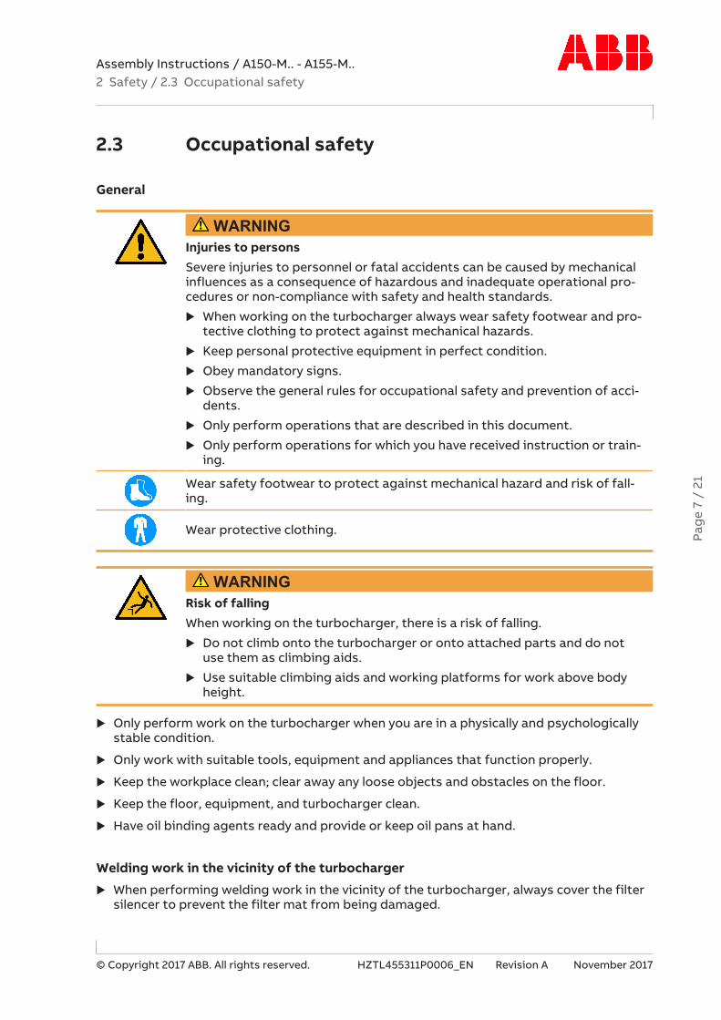
2.3 Occupational safety
General
WARNINGInjuries to personsSevere injuries to personnel or fatal accidents can be caused by mechanicalinfluences as a consequence of hazardous and inadequate operational pro-cedures or non-compliance with safety and health standards.
u When working on the turbocharger always wear safety footwear and pro-tective clothing to protect against mechanical hazards.
u Keep personal protective equipment in perfect condition.
u Obey mandatory signs.
u Observe the general rules for occupational safety and prevention of acci-dents.
u Only perform operations that are described in this document.
u Only perform operations for which you have received instruction or train-ing.
Wear safety footwear to protect against mechanical hazard and risk of fall-ing.
Wear protective clothing.
WARNINGRisk of fallingWhen working on the turbocharger, there is a risk of falling.
u Do not climb onto the turbocharger or onto attached parts and do notuse them as climbing aids.
u Use suitable climbing aids and working platforms for work above bodyheight.
u Only perform work on the turbocharger when you are in a physically and psychologicallystable condition.
u Only work with suitable tools, equipment and appliances that function properly.
u Keep the workplace clean; clear away any loose objects and obstacles on the floor.
u Keep the floor, equipment, and turbocharger clean.
u Have oil binding agents ready and provide or keep oil pans at hand.
Welding work in the vicinity of the turbocharger
u When performing welding work in the vicinity of the turbocharger, always cover the filtersilencer to prevent the filter mat from being damaged.
Pag
e 7
/ 21

Assembly Instructions / A150-M.. - A155-M..2 Safety / 2.3 Occupational safety
© Copyright 2017 ABB. All rights reserved. HZTL455311P0006_EN Revision A November 2017
u Keep flammable objects and substances out of the vicinity of flying sparks.
u Cover all connections on the turbocharger so that no foreign objects can enter the tur-bocharger.
u Wear personal protective equipment (PPE) for welding operations.
Mechanical hazards when working on the turbocharger
WARNINGPhysical hazards due to rotating partsThe rotor can rotate due to the stack draught alone. Contact with rotatingparts can cause severe injury.
u Secure rotor against turning.
WARNINGMechanical hazardSevere injuries to personnel or fatal accidents can be caused by mechanicalinfluences as a consequence of hazardous and inadequate operational pro-cedures.
u Observe the general rules for occupational safety and prevention of acci-dents.
u Ensure workplace safety.
u Only perform operations that are described in this chapter.
u Only perform operations for which you have previously received instruc-tion or training.
Hazards due to operating materials and supplies
Operating materials and supplies can include: Oils, greases, coolants, cleaning agents andsolvents, acids or similar substances.
Pag
e 8
/ 21

Assembly Instructions / A150-M.. - A155-M..2 Safety / 2.3 Occupational safety
© Copyright 2017 ABB. All rights reserved. HZTL455311P0006_EN Revision A November 2017
WARNINGHandling operating materials and suppliesSwallowing or inhaling vapours of operating materials and supplies or con-tact with them may be harmful to health. Flammable and combustible oper-ating materials and supplies can catch fire or resulting vapours can lead toan explosion.
u Do not breathe in these substances and avoid contact with the skin.
u Ensure proper ventilation.
u Observe the information in the material safety data sheet for the operat-ing materials and supplies.
u Comply with local legislation.
Wear safety goggles.
Wear safety gloves to protect against mechanical hazards.
Wear a respiratory mask to protect against gases.
Pag
e 9
/ 21

Assembly Instructions / A150-M.. - A155-M..3 Weight and transportation of the turbocharger /
© Copyright 2017 ABB. All rights reserved. HZTL455311P0006_EN Revision A November 2017
3 Weight and transportation of theturbocharger
Lifting gear with a sufficient load limit must be used for installing the turbocharger. The fol-lowing weight specification applies to the heaviest variant possible. Depending on the spe-cification, the weight specified on the rating plate may be lower than the standard valuespecified here.
Fig. 3: Suspension of complete turbocharger unit
A Complete turbocharger unit without gas outlet casingB Complete turbocharger unit with gas outlet casing
Product Weights [kg]A150-M 1200A155-M 1800Table 4: Weights of turbocharger A150-M.. – A155-M..
Pag
e 10
/ 2
1

Assembly Instructions / A150-M.. - A155-M..4 Installing the turbocharger / 4.1 Inserting gaskets
© Copyright 2017 ABB. All rights reserved. HZTL455311P0006_EN Revision A November 2017
4 Installing the turbocharger
4.1 Inserting gaskets
CAUTIONInserting the gasketsGaskets that are forgotten, damaged or improperly inserted will lead to oilleaks.
u Always use new gaskets and insert them carefully into the slot.
The necessary sealing is performed by O-rings which are located in the slots of the bearingcasing. The O-rings are supplied with the turbocharger.
Fig. 4: Inserting the gasket
42001 Bearing casing 01 Oil supply42200 O-ring 02 Oil drain42195 O-ring
Pag
e 11
/ 2
1

Assembly Instructions / A150-M.. - A155-M..4 Installing the turbocharger / 4.2 Placing the turbocharger on thebracket
© Copyright 2017 ABB. All rights reserved. HZTL455311P0006_EN Revision A November 2017
4.2 Placing the turbocharger on the bracket
Fig. 5: Fitting the turbocharger 1
Step A – Preparing the fixing screws
1. Insert expansion bush (42190) into bearing casing.
2. Screw the clamping nut (42201) flush onto the threaded rod (42191). The hexagon of thethread screw is at the top.
3. Place the thrust washer (01) of the clamping nut on the expansion bush and, with theclamping nut screwed on, guide the threaded rod through the thrust washer, expansionbush and bearing casing.
Step B – Preparing the positioning
u Screw the centering bush (42193) flush onto the threaded rod from below.
u Clean the surface of the bracket, the bearing casing, the centering bush and the centeringholes in the bracket.
u Make sure that the covers of the oil connections are removed.
u Make sure that the position of the oil inlet of the bracket matches the oil inlet hole in thebearing casing.
u Make sure that the O-rings are placed correctly in the slots.
Pag
e 12
/ 2
1

Assembly Instructions / A150-M.. - A155-M..4 Installing the turbocharger / 4.2 Placing the turbocharger on thebracket
© Copyright 2017 ABB. All rights reserved. HZTL455311P0006_EN Revision A November 2017
Fig. 6: Fitting the turbocharger 2
Product Dimension X Dimension LA150 112 ±2 mm 52 ±2 mmA155 144 ±2 mm 72 ±2 mmTable 5: Fitting the turbocharger, dimensions X, L
Step C – Aligning the turbocharger on the bracket
1. Lightly lubricate the hole, into which the centering bush (42193) is inserted, with screwgrease.
2. Position threaded rod with centering bush in the bracket.
3. Insert centering bush into bracket until the stop is reached.
4. Carefully lower turbocharger onto bracket and position using the centering bushes(42193) located in the bracket.
5. Check value x.
u If value x is not reached, the turbocharger must be lifted up from the bracket and re-aligned.
Step D – Fixing the threaded rod in place in the bracket
u Using the hexagon, screw the threaded rod into the bracket up to value L.
u If value L is not reached or the threaded rod jams while being screwed in, the threadedrod must be loosened by no more than ½ revolution (this will loosen the centering bushwhich may have jammed the rod). Then continue screwing in the threaded rod.
u If value L is not reached, undo the screw connection, carefully take the turbocharger offthe bracket and repeat the procedure starting with Step A.
u Observe the instructions for fastening the turbocharger with clamping nuts (see chapterFastening the turbocharger with a clamping nut →14).
Pag
e 13
/ 2
1

Assembly Instructions / A150-M.. - A155-M..4 Installing the turbocharger / 4.3 Fastening the turbocharger with aclamping nut
© Copyright 2017 ABB. All rights reserved. HZTL455311P0006_EN Revision A November 2017
4.3 Fastening the turbocharger with a clamping nut
Preparations for tightening the clamping nut
CAUTIONDo not clean pressure screws (04)The pressure screws are equipped with a permanent sliding layer that mustnot be removed.
Do neither clean nor lubricate the pressure screws. In case of non-compli-ance, it cannot be ensured that the necessary tension force is reached.
u Do not clean pressure screws.
u Do not lubricate pressure screws.
In order to correctly fit the clamping nuts, the pressure screws (04) must not protrude fromthe clamping nuts (03) in the direction of the thrust washer (02).
u Make sure the pressure screws do not protrude in the direction of the thrust washer.
Fig. 7: Preparing the clamping nut for the tightening procedure
1. Clean the thread of the bolt (01) and the contact surface.
2. Lightly oil the bolt thread.
3. Position the thrust washer (02) in place.
4. Tighten clamping nut (03) by hand.
5. Unscrew clamping nut (03) by ¼ of a turn (90°).
The distance between the thrust washer and the clamping nut is now about 1 mm.
Pag
e 14
/ 2
1

Assembly Instructions / A150-M.. - A155-M..4 Installing the turbocharger / 4.3 Fastening the turbocharger with aclamping nut
© Copyright 2017 ABB. All rights reserved. HZTL455311P0006_EN Revision A November 2017
Tightening pressure screws
Fig. 8: Tightening pressure screws
Torque-controlled tighteningProduct Fixing screw [mm] Tightening torques [Nm]A150 M30 45A155 M36 85Table 6: Pressure screw tightening torques
1. Screw in pressure screws crosswise by hand until reaching the stop.
2. Tighten pressure screws crosswise to 50 % of the tightening torque specified in thetable.
3. Tighten pressure screws crosswise to 100 % of the tightening torque specified in thetable.
4. Work in a circle to tighten all pressure screws to 100 % of the tightening torque specifiedin the table.
5. Tighten pressure screws to 100 % in 5 … 7 rounds until the required residual tighteningangle of < 20° is achieved.
Pag
e 15
/ 2
1

Assembly Instructions / A150-M.. - A155-M..4 Installing the turbocharger / 4.4 Connecting the turbocharger
© Copyright 2017 ABB. All rights reserved. HZTL455311P0006_EN Revision A November 2017
4.4 Connecting the turbochargeru Connect cable to speed sensor (86515).
u Connect all gas, water and air lines according to the instructions of the enginebuilder.
Version with compressor wheel cooling
CAUTIONFailure of compressor wheel coolingAny prolonged failure of the compressor wheel cooling will shorten the re-placement interval of the compressor wheel.
u Make sure there is an uninterrupted supply of cooling air during opera-tion.
Fig. 9: Connecting the compressor cooling air intake
u Remove the screw plug on the connection for the compressor wheel cooling (06) and fitthe cooling air line.
4.5 Attaching the support
Fig. 10: Attaching the support
u If present: Attach support (61301) to engine support or to a connecting piece.
Pag
e 16
/ 2
1

Assembly Instructions / A150-M.. - A155-M..5 Storage of new turbochargers and spare parts /
© Copyright 2017 ABB. All rights reserved. HZTL455311P0006_EN Revision A November 2017
5 Storage of new turbochargers andspare parts
Storage of new turbochargers and spare parts for up to 6 months
New turbochargers and spare parts can be stored in their closed packages for 6 monthsfrom the date of delivery without additional mothballing measures, indicated by the VCI la-bel on the package.
Fig. 11: Volatile Corrosion Inhibitor (VCI)
Only dry rooms with 40...70 % atmospheric humidity, in which no water condensation canform, are suitable as storage locations.
Storage of new turbochargers and spare parts for more than 6 months
WARNINGHealth protection when handling VCIVCI products are not hazardous in terms of the Ordinance on HazardousSubstances. Nevertheless, the following points must be observed whenhandling VCI:
u Observe information in material safety data sheet
u Ensure proper space ventilation.
u Do not eat, drink or store food at the workplace while working with VCI.
u Clean hands and face after working with VCI.
u For more information, see www.branopac.com.
Wear safety gloves to protect against mechanical hazards.
Every 6 months, the following mothballing measures are required:
u Open package.
u Remove VCI corrosion protection emitter from package and replace with a new VCI corro-sion protection emitter of the same kind. New VCI corrosion protection emitters can beobtained from www.branopac.com.
u Old VCI corrosion protection emitters must be disposed of in an environmentally compat-ible, professional way and in compliance with locally applicable regulations.
u Close package. The more tightly the package is sealed, the longer the protection dura-tion.
Pag
e 17
/ 2
1

Assembly Instructions / A150-M.. - A155-M..5 Storage of new turbochargers and spare parts /
© Copyright 2017 ABB. All rights reserved. HZTL455311P0006_EN Revision A November 2017
Long-term storage of replacement turbochargers or spare parts
The turbochargers or cartridge groups will be prepared for long-term storage if requested inthe purchase order. The package is equipped with a hygrometer (see illustration).
Fig. 12: Package with hygrometer
Every 6 months, the following measures are required:
u Check the hygrometer (02) in the sight-glass. There is an opening (01) in the woodencrate to enable you to perform this check. If the 70% indicator field has changed colour,the maximum admissible atmospheric humidity has been exceeded. In this case, the tur-bocharger or cartridge group must be checked and repackaged by an ABB TurbochargingService Station.
u Check the package for damage. If the package is damaged, the turbocharger or cartridgegroup must be checked and repackaged by an ABB Turbocharging Service Station.
After every 3 years, the following steps must be carried out by an ABB Turbocharging ServiceStation:
¡ Checking the component
¡ Replacing the desiccant
¡ Repackaging the component.
NOTICEReplacement components which are ready for operationIf the 70% field of the hygrometer (02) has not changed colour and the pack-age is not damaged, the replacement turbocharger or replacement cartridgegroup can be put into operation without previously having been checked byan ABB Turbocharging Service Station.
Unpackaging replacement turbochargers or spare parts
Once the material has been unpackaged from the VCI package, the corrosion protection isno longer effective.
To prevent condensation, the temperature of the package contents must be the same as theambient temperature.
Pag
e 18
/ 2
1

Assembly Instructions / A150-M.. - A155-M..5 Storage of new turbochargers and spare parts /
© Copyright 2017 ABB. All rights reserved. HZTL455311P0006_EN Revision A November 2017
Pag
e 19
/ 2
1

Assembly Instructions / A150-M.. - A155-M..6 Further information /
© Copyright 2017 ABB. All rights reserved. HZTL455311P0006_EN Revision A November 2017
6 Further informationThe Operation Manual must be observed with regard to commissioning, operation, mainten-ance and ordering spare parts.
NOTICEOperation ManualThe Operation Manual for the turbocharger with the relevant serial numberis available online on our website www.abb.com/turbocharging.
Fig. 13: Serial number of the turbocharger on the rating plate
One rating plate (01) each is attached on the left and the right side of the turbocharger bear-ing casing.
1. Read the serial number (02) on the rating plate (01) of the turbocharger.
u The Operation Manual can be found online in accordance with the details on the followingpage.
Pag
e 20
/ 2
1

Assembly Instructions / A150-M.. - A155-M..6 Further information /
© Copyright 2017 ABB. All rights reserved. HZTL455311P0006_EN Revision A November 2017
Fig. 14: Finding the Operation Manual online
Pag
e 21
/ 2
1

Operation Manual / Contact information
Further information
Find your local service team on our website (see section “contact us“ / “Contact information”).
Find and download the Operation Manual of your product on our website (see “Need product information” / “Operating instructions“).
© Copyright 2017 ABB. All rights reserved.
ABB Turbo Systems LtdBruggerstrasse 71 aCH-5401 Baden/ SwitzerlandPhone: +41 58 585 7777Fax: +41 58 585 5144E-mail: [email protected]
www.abb.com/turbocharging
Visit our website by scanning the QR code.
HZT
L455
311P
0006