original betriebsanleitung original instruction manual · 2019-09-27 · directive machines...
TRANSCRIPT

DNSR-2R Original Betriebsanleitung
Original Instruction Manual
wir sind sicherheit. we are safety

DNSR-2R Original Betriebsanleitung Original Instruction Manual
Stand 13.03.2018 Seite 2 von 16 Date 2018-03-13 Page 2 of 16

DNSR-2R Original Betriebsanleitung Original Instruction Manual
Stand 13.03.2018 Seite 3 von 16 Date 2018-03-13 Page 3 of 16
EU-Konformitätserklärung EU declaration of conformity Dichiarazione di conformità UE Dichiarazione di conformità UE Declaración UE de conformidad
Die nachfolgend aufgeführten Produkte sind konform mit den Anforderungen der folgenden Richtlinien The beneath listed products are in conformity with the requirements of the following directives Les produits mentionés ci-dessous sont conformes aux exigences imposées par les directives suivantes I prodotti sotto elencati sono conformi alle direttive sotto riportate Los productos listados a continuación son conforme a los requisitos de las siguientes directivas
Maschinenrichtlinie 2006/42/EG EMV Richtlinie 2014/30/EU RoHS-Richtlinie 2011/65/EU Machinery directive 2006/42/EC EMC Directive 2014/30/EU RoHS Directive 2011/65/EU Directive Machines 2006/42/CE Directive de CEM 2014/30/UE Directive de RoHS 2011/65/UE Direttiva Macchine 2006/42/CE Direttiva EMV 2014/30/UE Direttiva RoHS 2011/65/UE Directiva de máquinas 2006/42/CE Directiva CEM 2014/30/UE Directiva RoHS 2011/65/UE
Folgende Normen sind angewandt: a • EN 55011: 2009+A1: 2010, EN 61326-1: 2006-05 (Klasse B) Following standards are used: b • DIN EN 60947-5-1: Teil 5.1 Les normes suivantes sont appliquées: • SO DIN EN 13849-1/ Teil 1/ Funktionsart 1, 2 und 3 Kategorie 3, PLd
Funktionsart 4 und 4A: Kategorie 1, PLc Vengono applicate le seguenti norme: c • DIN EN ISO 13849-2 Se utilizan los siguientes estándares: d •
Zusatzanforderung: Supplementary requirements:
GS-ET-20 DIN EN ISO 9001: 2015/ DQS, Frankfurt, Reg.-Nr.:67542-01
Bezeichnung der Bauteile Descrizione dei componenti DNSR2R2 Not-Halt Relais Description of components Descripción de componente Emergency stop relay Description des composants
EG-Baumusterprüfbescheinigung EC-Type Test certificate ET 16095 vom 04.07.2016 ET 16095 from2016.07.04
Notifizierte Stelle Organismo notificato Fachausschuss für Elektrotechnik,
Prüf- und Zertifizierungsstelle Köln, Germany Europäisch notifizierte Stelle - Kenn-Nummer 0340,
Notified body Organismo notificado Organisme notifié
Bevollmächtigte Person für die Erstellung dieser Unterlagen
Authorized person for the issue of this document
Dirar Najib Esslinger Str. 84/ 72649 Wolfschlugen/ Germany
Wolfschlugen, 13. März 2018
Dirar Najib Geschäftsführer/ CEO

DNSR-2R Original Betriebsanleitung Original Instruction Manual
Stand 13.03.2018 Seite 4 von 16 Date 2018-03-13 Page 4 of 16
Inhaltsverzeichnis Contents Bestimmungsgemäße Verwendung: 5 Intended purpose: 5 Zertifizierungsdaten 5 Certificate data 5 Sicherheitsbestimmungen 6 Safety regulations 6 Wichtiger Hinweis und Validierung 7 Important notes and validation 7 Verwendung 33SR02 / 33SR03, 33SR04 8 Usage 33SR02 / 33SR03, 33SR04 8 Funktionsart 1 8 Function mode 1 8 Funktionsart 2 9 Function mode 2 9 Funktionsart 3 9 Function mode 3 9 Funktionsart 4 10 Function mode 4 10 Schaltzustandsanzeige 10 Switching status display 10 Betriebsart 4A 11 Function mode 4A 11 Schaltzustandsanzeige 12 Switching status display 12 Technische Daten 13 Technical data 14 Kontaktlebensdauer 13 Contact life 14 Abmessungen 15 Dimension 15 Einbau 15 Fitting 15 Ausbau 15 Remove 15
DNSR-2R Original Betriebsanleitung Original Instruction Manual
Stand 13.03.2018 Seite 5 von 16 Date 2018-03-13 Page 5 of 16
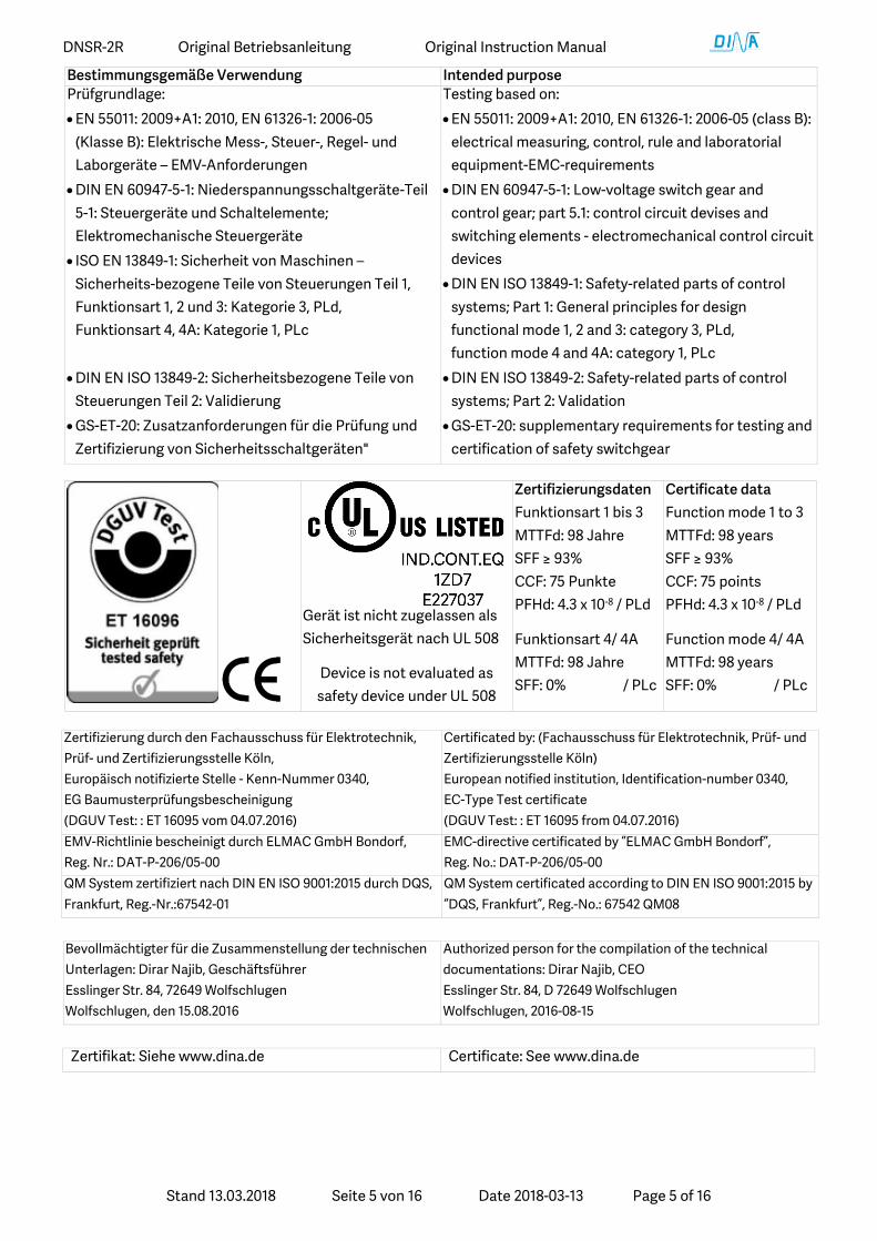
Bestimmungsgemäße Verwendung Intended purpose Prüfgrundlage: • EN 55011: 2009+A1: 2010, EN 61326-1: 2006-05
(Klasse B): Elektrische Mess-, Steuer-, Regel- und Laborgeräte – EMV-Anforderungen
• DIN EN 60947-5-1: Niederspannungsschaltgeräte-Teil 5-1: Steuergeräte und Schaltelemente; Elektromechanische Steuergeräte
• ISO EN 13849-1: Sicherheit von Maschinen – Sicherheits-bezogene Teile von Steuerungen Teil 1, Funktionsart 1, 2 und 3: Kategorie 3, PLd, Funktionsart 4, 4A: Kategorie 1, PLc
• DIN EN ISO 13849-2: Sicherheitsbezogene Teile von Steuerungen Teil 2: Validierung
• GS-ET-20: Zusatzanforderungen für die Prüfung und Zertifizierung von Sicherheitsschaltgeräten"
Testing based on: • EN 55011: 2009+A1: 2010, EN 61326-1: 2006-05 (class B):
electrical measuring, control, rule and laboratorial equipment-EMC-requirements
• DIN EN 60947-5-1: Low-voltage switch gear and control gear; part 5.1: control circuit devises and switching elements - electromechanical control circuit devices
• DIN EN ISO 13849-1: Safety-related parts of control systems; Part 1: General principles for design functional mode 1, 2 and 3: category 3, PLd, function mode 4 and 4A: category 1, PLc
• DIN EN ISO 13849-2: Safety-related parts of control systems; Part 2: Validation
• GS-ET-20: supplementary requirements for testing and certification of safety switchgear
Gerät ist nicht zugelassen als Sicherheitsgerät nach UL 508
Device is not evaluated as safety device under UL 508
Zertifizierungsdaten Funktionsart 1 bis 3 MTTFd: 98 Jahre SFF ≥ 93% CCF: 75 Punkte PFHd: 4.3 x 10⁻⁸ / PLd
Funktionsart 4/ 4A MTTFd: 98 Jahre SFF: 0% / PLc
Certificate data Function mode 1 to 3 MTTFd: 98 years SFF ≥ 93% CCF: 75 points PFHd: 4.3 x 10⁻⁸ / PLd
Function mode 4/ 4A MTTFd: 98 years SFF: 0% / PLc
Zertifizierung durch den Fachausschuss für Elektrotechnik, Prüf- und Zertifizierungsstelle Köln, Europäisch notifizierte Stelle - Kenn-Nummer 0340, EG Baumusterprüfungsbescheinigung (DGUV Test: : ET 16095 vom 04.07.2016)
Certificated by: (Fachausschuss für Elektrotechnik, Prüf- und Zertifizierungsstelle Köln) European notified institution, Identification-number 0340, EC-Type Test certificate (DGUV Test: : ET 16095 from 04.07.2016)
EMV-Richtlinie bescheinigt durch ELMAC GmbH Bondorf, Reg. Nr.: DAT-P-206/05-00
EMC-directive certificated by “ELMAC GmbH Bondorf”, Reg. No.: DAT-P-206/05-00
QM System zertifiziert nach DIN EN ISO 9001:2015 durch DQS, Frankfurt, Reg.-Nr.:67542-01
QM System certificated according to DIN EN ISO 9001:2015 by “DQS, Frankfurt”, Reg.-No.: 67542 QM08
Bevollmächtigter für die Zusammenstellung der technischen Unterlagen: Dirar Najib, Geschäftsführer Esslinger Str. 84, 72649 Wolfschlugen Wolfschlugen, den 15.08.2016
Authorized person for the compilation of the technical documentations: Dirar Najib, CEO Esslinger Str. 84, D 72649 Wolfschlugen Wolfschlugen, 2016-08-15
Zertifikat: Siehe www.dina.de Certificate: See www.dina.de

DNSR-2R Original Betriebsanleitung Original Instruction Manual
Stand 13.03.2018 Seite 6 von 16 Date 2018-03-13 Page 6 of 16
Sicherheitsbestimmungen • Das Gerät darf nur von einer Elektrofachkraft oder
unterwiesenen Personen installiert und in Betrieb genommen
werden, die mit dieser Betriebsanleitung und den geltenden
Vorschriften über Arbeitssicherheit und Unfallverhütung
vertraut sind.
• Beachten Sie die VDE- sowie die örtlichen Vorschriften,
insbesondere hinsichtlich der Schutzmaßnahmen.
• Halten Sie beim Transport, der Lagerung und im Betrieb die
Bedingungen nach EN 60068-2-6, 04/95 ein.
• Werden die Vorschriften nicht beachtet, kann Tod, schwere
Körperverletzungen oder hoher Sachschaden die Folge sein.
• Bei Not-Halt Anwendungen muss der automatische
Wiederanlauf der Maschine verhindert werden.
• Durch eigenmächtige Umbauten erlischt jegliche
Gewährleistung. Es können dadurch Gefahren entstehen, die
zu hohen Sachschaden, schweren Verletzungen oder sogar
zum Tod führen.
• Montieren Sie das Gerät in einen Schaltschrank; Staub und
Feuchtigkeit können sonst zu Beeinträchtigungen der
Funktionen führen. Der Einbau in einem Schaltschrank ist
zwingend.
• Sorgen Sie an allen Ausgangskontakten bei kapazitiven und
induktiven Lasten für eine ausreichende Schutzbeschaltung.
• Das Gerät ist unter Berücksichtigung der nach DIN EN 50274,
VDE 0660-514 geforderten Abstände einzubauen.
• Während des Betriebes stehen Schaltgeräte unter gefährlicher
Spannung. Schutzabdeckungen dürfen nicht entfernt werden.
• Wechseln Sie das Gerät aus nach dem ersten Fehlerfall und
entsorgen Sie es sachgerecht nach Ablauf der Lebensdauer!
• Bewahren Sie diese Produktinformation auf!
Safety regulations • The unit may only be installed and operated by those who
are qualified electrical engineers or have received sufficient
training and are familiar with both these instructions and
the current regulations for safety at work and accident
prevention.
• Follow VDE, EN as well as local regulations especially as
regards preventative measures!
• Transport, storage and operating conditions should all stick
to EN 60068-2-1, 2-2.
• Ignoring the safety regulations can lead to death, serious
injury or cause considerable damage!
• In emergency stop applications must ensure that the
machine cannot start up again automatically!
• Any guarantee is void following unauthorised
modifications. This can lead to death, serious injury or
cause considerable damage!
• The unit should be mounted in a cabinet with a protection
class of IP54. Otherwise dampness and dust could lead to
functional impairment. The installation in a control cabinet
is imperative.
• Adequate fuse protection must be provided on all output
contacts especially with capacitive and inductive loads.
• The unit must be installed following the specification of DIN
EN 50274, VDE 0660-514 regarding the required distances.
• During operation, parts of the electronic switchgear carry
high voltage. The protective covers must not be removed.
• The device must be replaced after the first malfunction and
properly disposed after reaches the end of it service life.
• Keep the operating instructions!

DNSR-2R Original Betriebsanleitung Original Instruction Manual
Stand 13.03.2018 Seite 7 von 16 Date 2018-03-13 Page 7 of 16
Wichtiger Hinweis und Validierung Important notes and validation • Das hier beschriebene Produkt wurde entwickelt, um
als Teil eines Gesamtsystems sicherheitsgerichtete
Funktionen zu übernehmen.
• Das Gesamtsystem wird durch Sensoren, Auswerte-,
Melde-einheiten sowie Konzepte für sichere
Abschaltungen gebildet.
• Es liegt im Verantwortungsbereich des Herstellers einer
Anlage oder Maschine die korrekte Gesamtfunktion
sicherzustellen.
• Der Hersteller der Anlage/Maschine ist verpflichtet, die
Wirksamkeit des implementierten Sicherheitskonzepts
innerhalb des Gesamtsystems zu prüfen und zu
dokumentieren.
• Dieser Nachweis ist nach jeglicher Modifikation am
Sicherheitskonzept bzw. Sicherheitsparametern erneut
zu erbringen.
• DINA Elektronik GmbH ist nicht in der Lage, alle
Eigenschaften eines Gesamtsystems, das nicht durch
DINA konzipiert wurde, zu garantieren.
• DINA Elektronik GmbH übernimmt auch keine Haftung
für Empfehlungen, die durch die nachfolgende
Beschreibung gegeben bzw. impliziert werden.
• Auf Grund der nachfolgenden Beschreibung können
keine neuen, über die allgemeinen Lieferbedingungen
der DINA Elektronik GmbH hinausgehenden Garantie-,
Gewährleistungs- oder Haftungsansprüche abgeleitet
werden.
• Zur Vermeidung von EMV-Störgrößen müssen die
physikalischen Umgebungs- und Betriebsbedingungen
am Einbauort des Produkts dem Abschnitt EMV der
DIN EN 60204-1 entsprechen.
• The product described here was developed to
perform safety related functions as part of a
complete system.
• The complete system consists of sensors, evaluation
and message units as well as concepts for safe
shutdowns.
• It is the responsibility of the manufacturer of a
system or machine to ensure the proper overall
function.
• The manufacturer of the system is required to test
and to document the effectiveness of the
implemented safety concept within the complete
system.
• This verification is to be performed after every
modification to the safety concept or to safety
parameters.
• DINA Elektronik is not in the position to guarantee
the properties a complete system that was not
designed by DINA.
• DINA Elektronik GmbH also accepts no liability for
recommendations that are given or implied by the
following description.
• No new guarantee, warranty or liability claims that
extend beyond DINA's general delivery conditions
can be derived on the basis of the following
description.
• To avoid EMC disturbances, the physical
environmental and operating conditions at the
installation location of the product must comply
with section EMC of DIN EN 60204-1.

DNSR-2R Original Betriebsanleitung Original Instruction Manual
Stand 13.03.2018 Seite 8 von 16 Date 2018-03-13 Page 8 of 16
Verwendung 33SR02 / 33SR03/ 33SR04 • Das Not-Halt Relais DNSR-2R ist vorgesehen zur
Stilllegung von Bearbeitungsmaschinen beim Auftreten von Gefahren.
• Die Kontakte sind als NO ausgeführt. • Die Kontakte 14, 24 und 24, 34 sind potential-
gebunden an 24V DC, andere sind potenzialfrei. • Sie sind so zu verwenden, dass die vorgesehene Not-
Halt Funktion ausgeführt wird. • DNSR-2R ist geeignet für Sicherheitskreisen nach
VDE 0113 Teil 1. • Abhängig von der DNSR-2R Version ist maximal
Kategorie 3 / PLd nach DIN EN ISO 13849-1 zu erreichen.
• DNSR-2R ist in einem 22.5mm Kunststoffgehäuse zum Einbau auf einer 35mm Norm Hutschiene vorgesehen.
• Bei allen Betriebsarten wird die Zeit werkseitig eingestellt
• Ein- und Ausgänge werden auf Plausibilität geprüft. • Ein Anschlussplan ist seitlich auf dem Gerät.
Usage 33SR02 / 33SR03/ 33SR04 • The emergency stop relay DNSR-2R is designated for
the shutdown of machining centre in the event of danger.
• All contacts are NO. • The contacts 14, 24 and 24, 34 are potential closed to
24V DC the others are potential free. • They are used to cause the designated emergency
stop function. • DNSR-2R proper for safety circuit according to
VDE 0113 part 1 • Depending of the version of DNSR-2R maximal
category 3 / PLd according to DIN EN ISO 13849-1 can be reached.
• DNSR-2R is mounted in a 22.5 mm plastic housing to be installed on a 35mm standard rail.
• The time delay for all function modes is ex works adjusted.
• The In- and outputs are checked for plausibility. • A connection plan is on the side of the unit.
Eigenschaften Features 33SR02 2 Diagnose Kontakte 1 Kontakt unverzögert 1 Kontakt rückfallverzögert Funktionsart 1 Kategorie 3, PLd
33SR03 2 Diagnose Kontakte 2 Kontakte rückfallverzögert Funktionsart 3 Kategorie 3, PLd
33SR02 2 diagnostics contacts 1 contacts undelayed 1 off delayed contact Functional mode 1 Category 3, PLd
33SR03 2 diagnostics contacts 2 off delayed contact Functional mode 3 Category 3, PLd
Funktionsart 1 • Diese Funktion ist ein einkanaliger Not-Halt Kreis mit
einem Start S12 und Quitt Kreis S34. • Beide Kreise werden über interne Spannung
15V an S11 und S33 angesteuert. • S11 ist geschaltet zu S12 und S33 zu S34 über Not-Halt
und Quitt Taster. • Nach dem Abschalten von S34 schließen alle
Kontakte. • Bei Unterbrechung von S12 schalten die Kontakte 24,
34 und 13-14 sofort ab. • Der Kontakt 47-48 öffnen rückfallverzögert. • Ein- und Ausgänge werden auf Plausibilität geprüft.
Functional mode 1 • This function is one channel emergency stop circuit
with a start S12 and quit circuit S34. • Both circuits are controlled via an internal voltage 15V
at S11 and S33. • S11 is switched on to S12 and S33 to S34 via the button
emergency stop and quit. • After the switching off of S34 all contacts are
immediately closed. • After the switching off of S12 the contacts 24, 34 and
13-14 open immediately. • The contact 47-48 will switch off delayed. • The In- and outputs are checked for plausibility.
Schema Schematic Betriebsart 1 Function mode 1
12 3 4 5 6 7 8
13 14 15 16
A1A2 24 34 S11 S12 S33 S34
15V 15V
ID-No: 33SR0213 14 47 48
13-1424 + 34
S12
S34
47-48 t

DNSR-2R Original Betriebsanleitung Original Instruction Manual
Stand 13.03.2018 Seite 9 von 16 Date 2018-03-13 Page 9 of 16
Funktionsart 2 • 2 Start (S12, S22) und 2 Quitt Kreise (S34, S44) sind
verfügbar. • Steuerung der Kreise erfolgt über interne Spannung
15V an S11, S33, 12V an S21, S43. • S11 ist geschaltet zu S12, S33 zu S34, S21 zu S22 und
S43 zu S44 über Not-Halt und Quitt Taster. • Nach Abschalten von S34 und S44 schließen alle
Kontakte sofort. • Wird S12 oder S12 und S22 getrennt, schalten die
Kontakte 14 und 24 sofort ab. • 37-38 und 47-48 schalten rückfallverzögert ab.
Functional mode 2 • 2 start (S12, S22) and 2 quit circuits (S34, S44) are
available. • The circuits control happens via internal voltage 15V
at S11 and S33, 12V at S21 and S43. • S11 is switched on to S12, S33 to S34, S21 to S22 and
S43 to S44 via emergency stop and quit button. • After switching off of S34, S44 all contacts close
directly. • After the switching off of S12 or S12 and S22 the
contacts 14 and 24 open immediately. • The contacts 37-38 and 47-48 switch off delayed.
Schema Schematic Betriebsart 2 Function mode 2
12 3 4 5 6 7 8
13 14 15 16
A1A2 14 24 S11 S12 S33 S34
15V 15VID-No: 33SR04
37 38 47 481211109
12V 12V
S21 S22 S43 S44
14+2437-38
S12+S22
S34+S44
47-48 t
Funktionsart 3 • 2 Start (S12, S22) und 1 Quitt Kreis (S34) sind
verfügbar. • Die Kreise werden über interne Spannung 15V an S11
und S33, 12V an S21 angesteuert. • S11 ist geschaltet zu S12, S33 zu S34 und S21 zu S22
über den Not-Halt und Quitt Taster. • Nach dem Abschalten von S34 schließen alle
Kontakte sofort. • Wird S12 oder S12 und S22 abgeschaltet, schalten die
Kontakte 14 und 24 sofort ab. • Die Kontakte 37-38, 47-48 schalten rückfallverzögert
ab. • Die Rückfallzeit wird intern eingestellt.
Functional mode 3 • 2 start circuits (S12, S22) and one quit (S34) are
available. • The circuits are controlled with internal voltage 15V at
S11 and S33, 12V at S21. • S11 is switched on to S12, S33 to S34 and S21 to S22 via
the emergency stop and button quit. • After switching off of S34 all contacts close
directly. • After the switching off of S12 or S12 and S22 the
contacts 14 and 24 open immediately. • The contacts 37-38 and 47-48 will switch off delayed.
• The time is adjusted internal.
Funktionsarten 1, 2 und 3: Kategorie 3, PLd Function modes 1, 2 and 3: category 3, PLd
Schema Schematic Betriebsart 3 Function mode 3
12 3 4 5 6
13 14 15 16
A1A2 14 24 S11 S12
15VID-No: 33SR03
37 38 47 481211109
12V
S21 S22
7 8S33 S34
15V
14+2437-38
S12+S22
S34
47-48 t

DNSR-2R Original Betriebsanleitung Original Instruction Manual
Stand 13.03.2018 Seite 10 von 16 Date 2018-03-13 Page 10 of 16
Funktionsart 4
• Diese Funktion hat 2 getrennte Steuerkreise jeweils
mit einem Start S12 und Quitt S34 kreis bzw. S22, S44.
• Die Kreise werden über interne Spannung 15V an S11
und S33, 12V an S21 und S43 angesteuert.
• S11 ist zu S12, S33 zu S34, S21 zu S22 und S43 zu S44
über den Not-Halt und Quitt Taster geschaltet.
• Nach dem Abschalten von S34 schließen die
Kontakte 14 und 37-38 sofort.
• Nach abschalten von S12 öffnet 14 sofort,
37-38 rückfallverzögert.
• Nach Abschalten von S44 schließen 24 und 47-48.
• 24 öffnet sofort und 47-48 rückfallverzögert, wenn S22
potentialfrei wird.
• Funktionsart 4 erreicht die Kategorie 1, PLc
Functional mode 4
• This function has 2 separate control circuits each
with one start S12, S22 and one quit S34, S44 circuit.
• The circuits are controlled with internal voltage 15V
at S11 and S33, 12V at S21 and S43.
• S11 is switched on to S12, S33 to S34, S21 to S22 and
S43 to S44 via the emergency stop and quit button.
• After switching off of S34 the contacts 14, 37-38
close directly.
• After a switching off of S12, 14 open directly.
37-38 off delayed.
• After a switching off of S44 24 and 47-48 close.
• 24 open immediately after the switching off of S22.
The contact 47-48 will switch off delayed.
• Function mode 4 enables the category 1, PLc
Schema Schematic Betriebsart 4 Function mode 4
12 3 4 5 6 7 8
13 14 15 16
A1A2 14 24 S11 S12 S33 S34
15V 15VID-No: 33SR04
37 38 47 481211109
12V 12V
S21 S22 S43 S44
14+2437-38
S12+S22
S34+S44
47-48 t
Schaltzustandsanzeige und Anmerkung
• Betriebsspannung eingeschaltet: LED ON leuchtet.
• Kreis 1 ist unterbrochen, Zeit läuft ab: LED K1 blinkt
• Kreis 2 ist unterbrochen, Zeit läuft ab: LED K2 blinkt
• K1, K2 leuchten bei richtiger Ansteuerung und aktiven
Kontakten.
• Zur Quittierung beide Start Kreise unterbrochen.
• Beide Kreise innerhalb 1s aktiv oder offen sein.
Switching status display and remark
• Power supply ON: LED ON illuminates
• Circuit 1 is switching off time is running out: LED K1 is
flashing
• Circuit 2 is switching off time is running out: LED K2 is
flashing
• Both LED illuminate with proper input signal and
closed contacts.
• To quit both start circuits have to be switched off.
• Both circuits have to be during 1s active or open.

DNSR-2R Original Betriebsanleitung Original Instruction Manual
Stand 13.03.2018 Seite 11 von 16 Date 2018-03-13 Page 11 of 16
Betriebsart 4A bei ID-No.: 33SR10, 33SR11, 33SR12 für Functional mode 4A with ID-No.: 33SR10, 33SR11, 33SR12 • Diese Betriebsart hat 2 getrennte Steuerkreise.
• Jeder Steuerkreis verfügt über einen Startkreis (S12)
bzw. (S22).
• Ansteuerung der Kreise über interne 15V an S11 und
12V an S21.
• S11 ist zu S12; S21 zu S22 über Steuertasten
geschaltet.
• ID-No. 33SR10: 37-38 und 45-48 (1.5s) Verzögerung
• ID-No. 33SR12: 37-28 (1.5s), 45-48 (50s) Verzögerung
• Wird S12 gegen S11 geschaltet, schließen die
Kontakt 14 und 37-38.
• Der Kontakt 14 öffnet sofort; 37-38 rückfallverzögert,
wenn S12 von S11 getrennt wird.
• Wird S22 zu S21 geschaltet, schließt der Kontakt 24
sofort und 45-48 anzugsverzögert.
• 24 und 45-48 öffnen sofort, wenn S22 von S21
getrennt wird.
• ID-No. 33SR11: 37/38 und 47/48 (15s) Rückfallzeit
• Wird S12 zu S11 geschaltet schließen die Kontakt 14
und 37-38 sofort.
• 14 öffnet sofort; 37-38 rückfallverzögert, wenn S12
von S11 getrennt wird.
• Wird S22 gegen S21 geschaltet schließen die
Kontakt 24 und 47-48 sofort. 24 öffnet sofort;
• 47-48 rückfallverzögert, wenn S22 von S21 getrennt
wird.
• This function has 2 separate control circuits
• Each control circuit has one start circuit S12
respectively S22.
• The circuits are controlled via internal voltage 15V at
S11, 12V at S21.
• S11 is switched on to S12, S21 to S22 via the control
button.
• ID-No. 33SR10: 37-38 and 45-48 (1.5s) delay time
• ID-No. 33SR12: 37-28 (1.5s), 45-48 (50s) delay time
• After the switching on of S12 to S11 the contact 14 and
37-38 closed.
• After the switching off of S12 of S11 the contacts 14
opens directly; 37-38 is off delayed.
• After the switching on of S22 to S21 the contact 24
closed directly and 45-48 is ON delayed.
• After a switching off of S12 of S11 the contacts 24 and
45-48 open directly.
• ID-No. 33SR11: 37/38 and 47/48 (15s) OFF delayed
• After the switching on of S12 to S11 the contact 14 and
37-38 closed.
• After the switching off of S12 to S11 the contacts 14
opens directly; 37-38 is off delayed.
• After the switching on S22 to 12V the contact 24 and
47-48 closed directly.
• After the switching off S12 to S11 the contacts 24 open;
47-48 is off delayed.
Schema Schematic Betriebsart 4A Function mode 4A
12 3 4 5 6 7 8
13 14 15 16
A1A2 14 24 S11 S12
15VID-No: 33SR10/ 12
37 38 45 481211109
12V
S21 S22PLc
14+24
37-38
S12+S22
47-48
t
t

DNSR-2R Original Betriebsanleitung Original Instruction Manual
Stand 13.03.2018 Seite 12 von 16 Date 2018-03-13 Page 12 of 16
Schema Schematic Betriebsart 4A Function mode 4A
12 3 4 5 6 7 8
13 14 15 16
A1A2 14 24 S11 S12
15VID-No: 33SR11
37 38 47 481211109
12V
S21 S22
14+2437-38
S12+S22
47-48 t
Schaltzustandsanzeige:
ON: Betriebsspannung
K1: Kontakt 14, 37-38
K2: Kontakt 24, 45-48 bzw. 24, 47-48
Switching status display
ON: Power supply
K1: contact 14 and 37-38
K2: contact 24 and 45-48 respectively 24 and 47-48
Die Ausgangskontakte 14 und 24 sind Diagnose
Kontakte für interne Fehler bzw. externe Ansteuerung
mit einem ungeeignetem Potential.
The output contact 14 and 24 are diagnostics contacts
for internal failure or an external control with
inappropriate potential.

DNSR-2R Original Betriebsanleitung Original Instruction Manual
Stand 13.03.2018 Seite 13 von 16 Date 2018-03-13 Page 13 of 16
Technische Daten Allgemeine technische Daten Betriebsspannung 24VDC +/- 10% Stromaufnahme ca. 40mA in Ruhestellung, ca. 70mA in Wirkstellung Sicherung Intern PTC Sicherung 200mA Betriebstemperatur / Lagertemperatur -10°C bis +60°C / -40°C bis +80°C Rüttelfestigkeit Sinus 10–50 Hz, 0,35mm, 10 Zyklen, 1 Oktave /min Maximaler Anschlussquerschnitt 1,5mm² mit Aderendhülsen Anzugsmoment bei Schraubklemme 05-06 Nm Anschlussdraht 60/75°C Kupfer Gehäusematerial Polyamid PA nicht verstärkt Schutzart Für Schaltschrankeinbau ≥ IP 54, Klemmen IP20 Technische Daten der Eingänge S12, S34 15V ± 0.5V intern an S11, S33 Prüfung gegen fremde Spannung S22, S44 12V ± 0.5V intern an S21, S43 Prüfung gegen fremde Spannung Technische Daten der Kontaktausgänge ID-No.: 33SR02, 33SR03, 33SR10, 33SR11, 33SR12 Potentialgebundene Kontakte 14, 24 und 34 (NO) minimal: 3mA, maximal: 0,5A aus Geräte Betriebsspannung Potentialfreie Kontakte Minimal: 10mA, maximal: 6A, Kontaktabsicherung 5A träge Schaltvermögen nach IEC/EN 60947-4-1 AC1: 230V / 6A, DC1: 24V / 6A, 100 000 Schaltspiele
Nach IEC/EN 60947-5-1 AC15: 230V/ 3A, 70.000 Schaltspiele, DC13: 24V/ 4A, 40.000 Schaltspiele
Mechanische Lebensdauer > 20 x 106 Schaltspiele Kontaktwerkstoff AgNi10 Maximale Schaltspiele 360 Zyklen/h bei max. Schaltstrom AC15+ DC13 Ansprechzeit, Rückfallzeit Typisch 10ms, Typisch 6ms Technische Daten der Kontaktausgänge ID-No.: 33SR20 Schaltstrom der Kontakte 15-16 und 25-26 Minimal 3mA, maximal 0.5A, Kontaktabsicherung 3A träge Schaltvermögen 17-18, 27-28 nach IEC/EN 60947-4-1
AC1: 250V/3A, DC1: 30V/3A, 150.000 Schaltspiele, Kontaktabsicherung 3A träge
Schaltvermögen nach IEC/EN 60947-5-1 AC15: 250V/ 0.2A, DC13: 30V/ 0.2A, 1 000.000 Schaltspiele Schaltvermögen nach IEC/EN 60947-5-1 AC15: 250V/ 1A, DC13: 30V/ 1A, 150.000 Schaltspiele Mechanische Lebensdauer > 20 x 106 Schaltspiele Ansprechzeit/ Rückfallzeit Typisch 10ms / Typisch 6ms Kontaktwerkstoff AgNi10 Maximale Schaltspiele 360 Zyklen/h bei max. Schaltstrom AC15 + DC13 Bemessungsisolationsspannung 17-18 und 27-28: 250V AC, 15-16 und 25-26: 30V Bemessungsisolationsspannung 250V AC, nicht für die Kontakte 14, 24, 34, 15-16 und 25-26 Stoßspannungsfestigkeit Verschmutzungsgrad 2 4KV, nicht für die Kontakte 14, 24, 34, 15-16 und 25-26
Kontaktlebensdauer
4 61053210.50.40.30.1 0.2
710
610
510
104Scha
ltspi
ele
/ Sw
itchi
ng c
ycle
s
Schaltstrom (A) / Switching current (A)
DC1: 24V
AC15 : 230V
AC1: 230V
DC13: 24V

DNSR-2R Original Betriebsanleitung Original Instruction Manual
Stand 13.03.2018 Seite 14 von 16 Date 2018-03-13 Page 14 of 16
Technical data General technical data Power supply 24VDC +/- 10% Current drain ca. 40mA relay off, ca. 70mA relay on Fuse Internal PTC fuse 200mA Operating temperature/ Storage temperature -10°C to +60°C / 40°C to +80°C Vibration resistance Sin 10 – 50 Hz, 0,35mm, 10 cycles, 1 Octave /min Maximal cable cross section 1,5 mm² with wire end sleeve Tightening torque with screw terminal 0,5-06 Nm Connection wire 60/75°C copper Housing material Polyamide PA non-reinforced Protection class Installation in a closed cabinet with ≥ IP54, terminals: IP20 Rated Isolation voltage 250V AC not for the contacts 14, 24, 34, 15-16 and 25-26 Technical data of inputs S12, S34 15V ± 0.5V, internal at S11, S33 test against other voltage S22, S44 12V ± 0.5V, internal at S21, S43 test against other voltage Technical data contact outputs ID-No.: 33SR02, 33SR03, 33SR10, 33SR11, 33SR12 Contacts closed to power supply, 14, 24 and 34 (NO) Minimal: 3mA, maximal: 0,5A from the power supply of the unit
Potential free contacts Minimal: 10mA, maximal: 6A, contact fuse 5A slow Switch current according to IEC/EN 60947-4-1 AC1: 230V / 6A, DC1: 24V / 6A, 100.000 cycles According to IEC/EN 60947-5-1 AC15: 230V/ 3A, 70.000 cycles, DC13: 24V/ 4A, 40.000cycles Mechanical life > 20 x 106 cycles Contact material AgNi10 Maximal cycles 360 cycles/h with maximal switching current AC15+ DC13 Reaction time / Drop out time Typical 10ms / Typical 6ms Technical data of the contact outputs ID-No.: 33SR20 Switch current; contacts 15-16 and 25-26 Minimal 3mA, maximal 0.5A, fuse 3A slow Switch current; contacts 17-18, 27-28 according to IEC/EN 60947-4-1 AC1: 250V/ 3A, DC1: 30V / 3A, 150.000 cycles
Switch current according to IEC/EN 60947-5-1 AC15: 250V/ 0.2A, DC13: 30V/ 0.2A, 1.000.000 cycles Switch current according to IEC/EN 60947-5-1 AC15: 250V/ 1A, DC13: 30V/ 1A, 150.000 cycles Mechanical life > 20 x 106 cycles Reaction time / Drop out time Typical 10ms / Typical 6ms Maximal cycles 360 cycles/h with maximal switch current AC15 + DC13 Contact material AgNi10 Isolation voltage 17-18 and 27-28: 250V AC, 15-16 and 25-26: 30V Impulse withstand voltage pollution degree 2 environment 4KV, not for the contacts 14, 24, 34, 15-16 and 25-26
Contact life
4 61053210.50.40.30.1 0.2
710
610
510
104Scha
ltspi
ele
/ Sw
itchi
ng c
ycle
s
Schaltstrom (A) / Switching current (A)
DC1: 24V
AC15 : 230V
AC1: 230V
DC13: 24V

DNSR-2R Original Betriebsanleitung Original Instruction Manual
Stand 13.03.2018 Seite 15 von 16 Date 2018-03-13 Page 15 of 16
Abmessungen Dimension
99
114
22.5
Einbau Fitting Ausbau Remove
70-75mm70-75mm(1)
(2) (3)

DNSR-2R Original Betriebsanleitung Original Instruction Manual
Stand 13.03.2018 Seite 16 von 16 Date 2018-03-13 Page 16 of 16
Wir sind Sicherheit We are safety. DINA Elektronik GmbH Esslinger Str. 84 D72649 Wolfschlugen Phone +49 7022 95170 Fax +49 7022 9517-710 [email protected] www.dina.de