original operating instructions - odfjell · 2 elevator links pn 134046-d - revision: 07 2016-05...
TRANSCRIPT

Man
ual P
N 1
3404
6-D
Rev
isio
n: 0
7, 2
016
-05
Operating Instructions • Pipe-Handling-Equipment • Hoisting Equipment
Forum B + V Oil Tools GmbH
Elevator Links
Elevator Links Connector*
Elevator Links Extension
Operating InstructionsOriginal Operating Instructions
*Patent Pending

2 Elevator Links PN 134046-D - Revision: 07 2016-05
Operating Instructions
Revision historyVersion Date Author Changes
00 2013-10 B+VOT ROK Updated Version, New Layout Elevator Links (Rev.: 009) HE, Elevator Links Connector (554106-D Rev.: 002), and Elevator Links Extension (New) YI
01 2014-01 B+VOT ROK VE/AG/MH
Initial Release
02 2014-03 B+VOT ROK,, MH Product Update
03 2014-04 Forum B + V Oil Tools, ROK, MH Product name changed
04 2014-05 Forum B + V Oil Tools, ROK, MH Rework of Part PN234000, Installation checklist added
05 2014-11 Forum B + V Oil Tools, ROK, MH Design Change for Links Connector
06 2015-10 Forum B + V Oil Tools, ROK, MH Company Name Change 1500t link added
07 2016-05 Forum B + V Oil Tools, ROK, MH Re-Design Links Connector
Document Approval
Version Author Eng. Check Appoval Check
07 Forum B + V Oil Tools MH 04/2016
Forum B + V Oil Tools FS 05/2016
Forum B + V Oil Tools
© Copyright 2016
All rights reserved at:
Forum B + V Oil Tools GmbH
D-20457 Hamburg (Germany)
Hermann-Blohm-Strasse 2
fon: +49-40 37 02 26 855
fax: +49-40-37 02 26 896
The copyright protection claimed includes all forms and matters of copyrighted material and information now allowed by statutory or judicial law or hereinafter granted.
All product names and product numbers mentioned in this publication are trademarks of Forum B + V Oil Tools GmbH. Other company brands and product names may be trademarks or registered trademarks of the respective companies and are also acknowledged.
All data in this manual takes place using best knowledge. Depending on ongoing technical improvements (ISO 9001), the Forum B + V Oil Tools GmbH reserves the right to make alterations to the design and specifications without notice. The values specified in this manual represent the nominal value of a unit produced in series. The values in individual units may have slight differences.
Only with written consent from Forum B + V Oil Tools GmbH the contents of this Instructions may be passed on to third persons. Especially procedure descriptions and explanations are not to be passed on to third persons.
Copying or multiplying for internal use is permitted.
We are grateful for suggestions and critic regarding this documentation or the product itself.
Printed in Germany.

32016-05 PN 134046-D - Revision: 07 Elevator Links
Operating Instructions
DES
CRI
PTIO
NSA
FETY
INST
ALL
ATI
ON
OPE
RA
TIO
NIN
SPEK
TIO
N /
MA
INTE
NA
NC
ESE
RVIC
EST
OR
AG
EA
PPEN
DIX
5 SERVICE 405.1 Malfunction 405.2 Repair 405.2.1 Repair by Customer 40
5.2.2 Repair by Manufacturer 40
5.2.3 Securing Screws with Nord Lock washers 40
5.3 Drawing, Parts List and Spare Parts 415.3.1 Contact to Parts Department 41
5.3.2 554150 Link Connector 42
5.3.3 Link Extension 43
6 INSPECTION / MAINTENANCE 466.1 Lubrication 476.1.1 Lubrication steps 47
6.1.2 Lubrication Points Elevator Link Extension 47
6.1.3 Lubrication Intervals 47
6.2 Inspections 486.2.1 Inspection of Hydraulic Equipment 48
6.2.2 Inspection Following Critical Loads 48
6.2.3 Inspection Following Removal 48
6.3 Inspection Categories 496.3.1 Inspection Category I 49
6.3.2 Inspection Category II 49
6.3.3 Inspection Category III 49
6.3.4 Inspection Category IV 49
6.4 Inspection Intervals and inspection tasks 506.4.1 Measuring of wear 52
6.4.2 Wear table Elevator Links 53
6.4.3 Wear table Elevator Links Connector 54
6.4.4 Wear table Elevator Links Extension 54
6.4.5 Critical area overview 55
6.5 Cleaning 576.5.1 Time of Cleaning 57
6.5.2 Procedure and Cleaning Agents 57
7 STORAGE / DISPOSAL 607.1 Storage 607.1.1 Short-term Storage after Use and for Less Than Three Months 60
7.1.2 Long-term Storage for More Than Three Months 60
7.2 Disposal 617.3 List of Service Products Used 61
8 APPENDIX 64A. Sample of EC Declaration of Conformity 65B. Third Party Documents 67I Nord Lock Washer (excerpt from Third Party Product information) 67
II Data-sheet Grease 72
III Data-sheet RUD VRSF 76
Table of contents
A. GENERAL 5I Basic Information 5II Intended Use 5III Improper Use 5IV Warranty and Liability 6V Obligations of the Operating Company 7VI Safety Symbols 9VII Personal Protective Equipment (PPE) 10VIII Conformity 11IX Contact Forum B + V Oil Tools worldwide 11X Information on the Forum B + V Oil Tools homepage 12
1 DESCRIPTION 141.1 Operation manual content 141.2 Technical Data 151.2.1 Elevator Links 15
1.2.2 Elevator Link Extension 17
1.2.3 Elevator Link Connector 18
1.3 Optional Accessories 191.4 Recommended Lubricants 191.5 Operational Environment 201.6 Machine Markings 20
2 SAFETY 222.1 General Safety Precautions 222.2 Safety Equipment 222.3 Safety Precautions 222.4 Operating Manual and Machine 232.5 Organizational Measures 232.6 Safety Precaution against Remaining Hazards 242.6.1 Danger of Pinching/Crushing 24
2.6.2 Human Error 25
2.7 Accidents, Fire 25
3 TRANSPORT / SETUP 283.1 Delivery 283.1.1 Scope of Delivery 28
3.1.2 Unpacking and Disposal of Packing Material 28
3.1.3 Intermediate Storage 28
3.2 Transport 293.2.1 Weights 30
3.2.2 Transport to Installation Site 30
3.3 Setup 30
4 COMMISSIONING AND OPERATION 324.1 Commissioning 324.1.1 Initial operation 32
4.1.1.1 Mounting the Elevator Links 33
4.1.1.2 Mounting Elevator Links to the Top Drive System (Hook) 33
4.1.1.3 Mounting the Elevator Link Extension to the Elevator Links 34
4.1.1.4 Mounting the Elevator Link Connectors to the Elevator Links 35
4.1.2 Installation Checklists 37
4.1.3 Installation Checklist Links Extension 37
4.1.4 Installation Checklist Link Connector 37
4.2 Operation 38

4 Elevator Links PN 134046-D - Revision: 07 2016-05
Operating Instructions
DESC
RIPTION
SAFETY
INSTA
LLATIO
NO
PERA
TION
INSPEC
TION
/ M
AIN
TENA
NC
ESERV
ICE
STOR
AG
EA
PPEND
IX
Table of contents
52016-05 PN 134046-D - Revision: 07 Elevator Links
Operating Instructions
GEN
ERA
L
A. General
I Basic Information
This operation manual refers to the Elevator Links (hereinafter called Links) from Forum B + V Oil Tools for use on oil platforms and oil drilling ships.
This operating manual is covering the Elevator Links extensions and Elevator Links connectors which are effective in conjunction with the use of the Forum B + V Oil Tools Links.
The permissible range of the Links is specified in the technical data (see „Technical Data“ on page 15).
This operating manual is intended for the operator of the Links. It is intended to ensure safe operation and must be read carefully and kept where it is accessible for Links) users at all times.
This operating manual contains all information on safe and proper operation of the Links. Observance of these instructions is the prerequisite for safe operation.
In addition it is necessary to observe all applicable national and local regulations, e.g. accident prevention regulations and environmental regulations as well as the company’s own internal safety regulations.
For installation, maintenance and repair work and proper training of the operating personnel Forum B + V Oil Tools recommends requesting service from Forum B + V Oil Tools itself.
II Intended Use
The Forum B + V Oil Tools Links are designed to be used for vertical lifting and holding elevators. The Links conduces as an association between the Top Drive and the elevators. The load capacity is limited in vertical direction only. The load capacity of the Links is not given in general for tilting of the links up to a defined degree. The load capacity has to be calculated as changed depending on the Links length and tilting degree. The utilisation of the Links is only allowed for the intended use.
The load capacity for certain operations can be calculated on request. If no load capacity for tilting the Links is given the tilting of the Links is prohibited. An abuse through tilting the Links , in this sense, can cause dangerous situations. The use is allowed only for the vertical holding of elevators. Details given in chapter „Technical Data“ on page 15 must be respected.
Additionally the intended use covers the compliance and observance of all procedures and safety notes of this manual as well as performing all necessary maintenance work in the given intervals.
INFOIn this documentation the abbreviation t and the word tons are used to describe short tons. If the metric ton is referred it will explicit be named in the text.
(1 tons = 2000 lb = 907,18474 kg)
III Improper Use
INFOImproper use of the machine releases Forum B + V Oil Tools from any liability for personal injury or property damage resulting therefrom.
Only the intended use of the Links is allowed. Always observe the specifications in chapter „Technical Data“ on page 15.
The following is specifically prohibited:
- Increasing the load limit of the Links
- Every use of the Links which is not intended.
Moreover operation of the Links is prohibited under the following conditions:
- When the machine or parts thereof are damaged or when the additional equipment is not installed properly.
- When protective or safety equipment is damaged, unusable, improperly installed or not present.
- When the Links are not operating properly.
- When humans or foreign objects or personnel are located in the hazard area of the Links.
- When conversions or modifications have been performed without previous, written approval by Forum B + V Oil Tools.
- When tools not approved by Forum B + V Oil Tools are used.
- When the prescribed maintenance intervals have been exceeded.
- When replacement parts not approved by Forum B + V Oil Tools are used.
- When repair or service work has been performed on the machine by companies not authorized by Forum B + V Oil Tools.
Observe also the chapter “Guarantee and Liability”

6 Elevator Links PN 134046-D - Revision: 07 2016-05
Operating Instructions
GEN
ERA
L
- Impermissible structural modifications;
- Use of replacement parts not approved by Forum B + V Oil Tools ;
- Normal wear or insufficient inspection of components subject to wear;
- External effects or force majeure.
- Greasing the Elevator Links with other greases as recommended by Forum B + V Oil Tools
INFOAny structural modification to the machine by the operating company requires previous written approval by Forum B + V Oil Tools . Failure to obtain such approval voids the warranty as well as the declaration of conformity and releases Forum B + V Oil Tools from any product liability.
Following modifications or installation of optional equipment all safety equipment must be reinstalled and checked by the operator for proper function.
IV Warranty and Liability
Liability
The technical information, data and instructions for operation contained in this operating manual correspond to the status at the time of print and are provided according to the best of our knowledge in consideration of our previous experience and know-how.
We reserve all rights to make technical modifications within the scope of technical development of the Elevator Links treated in this operating manual. Claims or entitlements cannot be deduced or derived from information, illustrations and descriptions in this operating manual.
Forum B + V Oil Tools is liable for all warranty obligations made within the scope of the contract for any faults or omissions on our part, excluding further claims. Claims for damages suffered are excluded regardless of the legal grounds.
Translations are complete according to best knowledge. We cannot assume any liability for translation errors, even when the translation was accomplished at our order. Only the original text is binding.
The descriptions and illustrations do not necessarily reflect the scope of delivery or any parts orders. The drawings and illustrations are not to scale.
Warranty
Forum B + V Oil Tools general terms of purchase and delivery apply. Purchasers recognize these conditions on the day the contract is signed at the latest.
The terms and duration of Forum B + V Oil Tools warranty are specified in the sales documents as well as the order confirmation. These will be submitted to the operating company as information at the time the contract is signed at the latest.
The manufacturer assumes no warranty whatsoever for damage or interruptions in operation resulting from failure to observe the operating instructions.
The operating manual is to be supplemented by the operating company with operating instructions based on existing national regulations on accident and environmental protection, including information on supervisory and reporting obligations taking into consideration operating peculiarities, e.g. in regard to work organization.
Warranty claims, complaints within the scope of the guarantee and liability for personal injury and property damage are excluded, when such result from any of the following causes:
- Any use other then intended;
- Improper installation, operation, maintenance or repair;
- Operation with defective safety equipment or improperly attached or non-operational safety or protective equipment or devices;
- Failure to observe the instructions in the operating manual regarding safe conduct;

72016-05 PN 134046-D - Revision: 07 Elevator Links
Operating Instructions
GEN
ERA
L
Requirements for Operator
Basic knowledge of safe handling and use of the Links includes knowledge of the general safety precautions.
Ensure that the Elevator Links is operated only in compliance with the general safety precautions and other instructions in this manual.
Training
The operating company is obligated to organize and hold regular training to ensure that all personnel involved with transporting, installing, operating and/or servicing the Links is familiar with the required procedures and safety precautions.
Minimum Qualifications
All work on the machine requires special knowledge and qualifications on the part of the operating personnel.
All personnel working on Links must have the following qualifications:
- Personal suitability for the work performed.
- Suitable qualifications for the work performed.
- Familiarity with the safety equipment and its function.
- Familiarity with this operating manual - particularly the safety precautions - and all chapters relevant for the work to be performed.
- Familiarity with the elementary instructions on operating safety and accident prevention.
In general all employees must have one of the following minimum qualifications:
- Technical training for independent work on the Elevator Links.
- Sufficient qualifications for working on the Elevator Links under supervision and at the instructions of a trained specialist.
V Obligations of the Operating Company
Planning and Checking Safety Measures
The obligation of the operating company to due diligence includes planning safety measures and supervising their observance.
All personnel performing work on or with the Links must be trained by the operating company for the work performed on the Links.
The personnel must have read and understood the operating manual.
Minimizing Risk of Injury
The following principles apply to minimize the risk of injury:
• Ensure that work on the Links is performed only by qualified personnel.
• The personnel must be authorized for such work by the operating company.
• The personnel must wear the prescribed protective equipment.
• Procedures, competencies and responsibilities must be clearly defined and established in the area of the Links. Proper behaviour in the event of a malfunction must be clear for everyone. The personnel must be given regular training.
• All WARNING signs and information on the Links must be complete and easily legible. For this purpose WARNING signs and information are to be cleaned regularly and replaced as required.
Trouble-free Operation
The following principles apply for trouble-free operation:
• Keep the complete operating manual at the location where the Links is in operation where it is easily accessible for everyone and in an easily legible condition.
• Use the Links exclusively for its intended purpose.
• Use the Links only when it is in a perfect operating state.
• Before starting work, check to ensure that it is in a safe operating state and functioning properly.
8 Elevator Links PN 134046-D - Revision: 07 2016-05
Operating Instructions
GEN
ERA
L
User Groups
This operating manual is subdivided into the following user groups:
Personnel Qualifications
Operating personnel Sufficiently trained in
Functional procedures on the machine
Operating procedures
Knowledge:
Competency and responsibility in regard to the work to be performed
Behaviour in emergencies
Service personnel Sound knowledge of
Mechanics
Hydraulics
Electrical engineering
Authorizations (according to standards of safety engineering):
Starting up machines
Grounding machines
Marking of machines
Sound knowledge of installation and operation of the Elevator Links.
Special Technical Knowledge
The following work should be performed only by specially trained personnel:
Work Performed
Qualifications
Work on hydraulic system
Special knowledge and experience with work on hydraulic systems.
Work on mechanical parts
Personnel qualified or trained in industrial mechanics; work is to be performed only under supervision and on instructions of a person qualified according to generally accepted codes of practice in industrial mechanics.

92016-05 PN 134046-D - Revision: 07 Elevator Links
Operating Instructions
GEN
ERA
L
Preliminary Safety Precautions
Safety precautions are given in the preceding form at the beginning of complete chapters or sections. They apply for the entire chapter or the entire subsequent section.
Safety Precautions Relevant for Action
If a safety precaution applies only for one single action or a short series of actions, it is integrated into the text preceding the possible hazard point.
For example:
1. Attach hoisting gear to eye bolts in cover.
CAUTION Danger of pinching/crushing hands! The cover can fall shut when the retainer is not engaged. Never open the cover by hand.
2. Open the cover with a crane and suitable hoisting gear.
3. Unscrew the M10 bolts on the hydraulic assembly with a 17 mm box wrench.
4. .
Instructions for Safe Procedure
Special work steps to ensure Safe Procedure are depicted as follows (example):
Safe Procedure5. Shut off machine.
6. Disconnect supply lines.
7. Attach machine to crane.
8. .
VI Safety Symbols
The safety precautions in this document contain standardized depictions and symbols. Four hazard classes are distinguished depending on the probability of occurrence and severity of the consequences.
Selection of the WARNING category depends on the probability of occurrence and the possible extent of damage.
NOTE
Situations which could result in damage to the machine or its surroundings or to tools are distinguished in this manner, supplemented, where applicable, by a pictograph.
CAUTIONIndication of recognizable hazard for humans or possible property damage.
Failure to observe can lead to reversible injuries or property damage!
The symbol as specified in ANSI Z535.6 emphasizes the cause.
Measures for avoiding are listed.
WARNINGIndication of recognizable hazard for humans.
Failure to observe can lead to irreversible injuries!
The symbol as specified in ANSI Z535.6 emphasizes the cause.
Measures for avoiding are listed.
DANGERIndication of imminent hazard for humans.
Failure to observe can lead to irreversible or lethal injuries!
The symbol as specified in ANSI Z535.6 emphasizes the cause.
Measures for avoiding are listed.

10 Elevator Links PN 134046-D - Revision: 07 2016-05
Operating Instructions
GEN
ERA
L
VII Personal Protective Equipment (PPE)
The following symbols located at appropriate points in the operating manual indicate that it is mandatory to wear personal protective equipment:
WEAR PROTECTIVE GLOVES!
WEAR EYE PROTECTION!
WEAR SAFETY SHOES!
WEAR PROTECTIVE HELMET!
WEAR EAR PROTECTION!
Linguistic Conventions
This documentation uses terms and symbols intended to help you find information more easily, perform work steps more effectively and recognize dangerous situations more quickly. These symbols and terms are explained below:
All important text sections are printed in bold face.
- Lists without any necessary sequence are marked with a dash (-) at the left side of the column.
• Individual activities to be performed are indicated by a dot (●) to the left of the column.
Relevant consequences of an action or work step are marked with an arrow (●) in the left margin.
Enumerations in a certain sequence (e.g. a series of work steps) are indicated by sequential numbers (1, 2, 3,. ) in the left margin.
For example:
1. Unscrew nuts on machine feet.
2. Lift machine.
For greater clarity the illustrations are located in the right column with the text opposite or directly below the associated text section. Larger illustrations extending over the entire width of the page are located before the explanatory text. The illustrations are provided with captions in telegraph style.
Fig. 1: Illustration Example Machine
INFO
Additional information and relationships requiring special attention are distinguished in this manner.

112016-05 PN 134046-D - Revision: 07 Elevator Links
Operating Instructions
GEN
ERA
L
VIII Conformity
The Links satisfy all requirements in applicable directives and standards. A sample of the EC Declaration of Conformity is given in the appendix.
INFO
This operating manual is a part of the technical documentation for the Elevator Links.The EC Declaration of Conformity is delivered together with the Links. [An example can be found in the appendix]Keep these instructions and the associated documents for later use.
IX Contact Forum B + V Oil Tools worldwide
In the event of problems that cannot be solved with the aid of this manual, please contact one of the following addresses.
Forum B + V Oil Tools GmbH
Hermann-Blohm-Straße 2
20457 Hamburg
Federal Republic of Germany
fon: +49 40 37 02 26 855
fax: +49 40-37 02 26 896
www.blohmvoss-oiltools.com
Forum Energy Technologies Regional Drilling locations
Drilling Service
6535 Guhn Road
Houston
TX 77040
USA
fon: +1 71 36 09 98 08 – 24 hour hotline
Drilling Sales Headquarters
10344 Sam Houston Park Drive, Suite 300
Houston
TX 77064
USA
fon: +1 71 33 51 79 00
Drilling Regional Offices
Unit 7, Murcar Industrial Estate Denmore Road
Bridge of Don Aberdeen
AB23 8JW UK
fon: +44 12 24 70 78 00
Oilfields Supply Center
Building B-20/21
Jebel Ali Free Zone Dubai
UAE
fon: +97 14 88 35 266
Drilling Regional Office
No 51 Benoi Road #06-00
Liang Huat Industrial Complex,
Singapore 629908
fon: +65 64 65 48 50 Out of hours +65 91 38 98 12
fax: +65 64 65 48 51

12 Elevator Links PN 134046-D - Revision: 07 2016-05
Operating Instructions
GEN
ERA
L
X Information on the
Forum B + V Oil Tools homepage
INFOFor further and actual information you can also visit our homepage in the internet.
A digital version of the operation instructions for this product as well as the operation instructions, safety- and update notes for other Forum B + V Oil Tools products can be reached via the Forum B + V Oil Tools homepage.
To join our internet Technical Documentation service with the latest updates on new technical documentation in a free and easy way, you must register to our service with your email-address and name in the customer-login area
q on www.blohmvoss-oiltools.com .
Fig. 2: Illustration Service - Homepage
q

132016-05 PN 134046-D - Revision: 07 Elevator Links
Operating Instructions
DES
CRI
PTIO
N
DESCRIPTION

14 Elevator Links PN 134046-D - Revision: 07 2016-05
Operating Instructions
GEN
ERA
LG
ENER
AL
DESC
RIPTION
INFOIn this documentation the abbreviation t and the word tons are used to describe short tons. If the metric ton is referred it will explicit be named in the text.
(1 tons = 2000 lb = 907,18474 kg)
Fig. 3: Elevator Links Fig. 4: Elevator Links Extension Fig. 5: Elevator Links Connector*
Pos Name Pos. Name1 Solid Elevator Links 3 Elevator Links Connector*
2 Elevator Links Extension
1 DescriptionThe Forum B + V Oil Tools Links are made as a pair of high-quality, heat treated and tested steel.
The safety factor and the test inspection of the Links meet the requirements of API Spec 8C. A stress test with 1.5 times the load rating was carried out on the Links.
The Forum B + V Oil Tools Links are a connecting element between the top drive system (hook) and the load (tubing). The load capacity is limited in the vertical direction only.
1.1 Operation manual contentThis manual describes is valid for the below described Forum B + V Oil Tools Links. A catalogue of links lengths and load capacity, is placed in the following chapter. A parts list of all modules of the Forum B + V Oil Tools Links is placed in the section „Service“.
wq e
*Patent Pending

152016-05 PN 134046-D - Revision: 07 Elevator Links
Operating Instructions
GEN
ERA
LG
ENER
AL
BESC
HRE
IBU
NG
DES
CRI
PTIO
N
1.2 Technical Data
Environmental conditions
Temperature range*-20 °C to +80 °C (-4 °F to +176 °F)
* Unless not stated otherwise in the data book.
1.2.1 Elevator Links
P/N SizeLoad rating (tons)
Weight per set kg [lbs]
134048-Y 1.3⁄4" x 48" 150 154 [340]
12" increases 150 18 [40]
134144-Y 1.3⁄4" x 144" 150 298 [657]
214048-Y 2.1⁄4" x 48" 250 178 [392]
12" increases 250 23 [51]
214180-Y 2.1⁄4" x 180" 250 428 [944]
214240-Y 2.1⁄4" x 240" (20 ft) 250 544 [1200]
214360-Y 2.1⁄4" x 360" (30 ft) 250 772 [1702]
214480-Y 2.1⁄4" x 480" (40 ft) 250 1000 [2205]
234048-Y 2.3⁄4" x 48" 350 270 [595]
12" increases 350 33 [73]
234216-Y 2.3⁄4" x 216" 350 726 [1601]
234240-Y 2.3⁄4" x 240" (25 ft) 350 790 [1742]
N/A 60 " (5 ft) increases 350 163 [359]
234600-Y 2.3⁄4" x 600" (50 ft) 350 1766 [3894]
234720-Y 2.3⁄4" x 720" (60 ft) 350 2090 [4608]
312072-Y 3.1⁄2" x 72" 500 480 [1058]
12" increases 500 44 [97]
312216-Y 3.1⁄2" x 216" 500 1098 [2421]
312240-Y 3.1⁄2" x 240" (20 ft) 500 1200 [2646]
60" (5 ft) increases 500 271 [598]
312660-Y 3.1⁄2" x 660" (55 ft) 500 3100 [6836]
312720-Y 3.1⁄2" x 720" (60 ft) 500 3300 [7277]
434108-Y 4.3⁄4" x 108" 750 1028 [2267]
12" increases 750 76 [168]
434216-Y 4.3⁄4" x 216" 750 1710 [3771]
434240-Y 4.3⁄4" x 240" (20 ft) 750 1862 [4106]
60" (5 ft) increases 750 379 [836]
434660-Y 4.3⁄4" x 660" (55 ft) 750 4514 [9953]
512180-Y 5.1⁄2" x 180" 1000 2630 [5799]
512180-Z-1250 5.1⁄2" x 180" 1250 2630 [5799]
512192-Z-1250 5.1⁄2" x 192" 1250 2714 [5984]
512200-Z-1250 5.1⁄2" x 200" 1250 2770 [6108]
512216-Z-1250 5.1⁄2" x 216" 1250 2882 [6355]
512240-Z-1250 5.1⁄2" x 240" 1250 3050 [6725]
612240-Z-1500 6.1⁄2” x 240” 1500 3213 [7084]For the 1000 and 1250 tons Forum B + V Oil Tools Links as well as for other sizes the technical data can also be provided upon request.

16 Elevator Links PN 134046-D - Revision: 07 2016-05
Operating Instructions
GEN
ERA
LG
ENER
AL
DESC
RIPTION
h
dg
f e
c
a
1.3/4"
2.1/4"-3.1/2"
4.3/4"
5.1/2"
6.1/2"
UPPER EYE LOWER EYE
b xleng th as ordered
Fig. 6: Elevator Links Measures
sh tons Measure x a b c d e f g h
150 1.3⁄4“ 2.1⁄4" 4.3⁄16" 5.1⁄2" 3" 5.1⁄4" 13" 3.3⁄4" 11.3⁄8" 8.1⁄2"
250 2.1⁄4“ 2.2⁄5" 5.1⁄2" 8" 3" 8" 10.1⁄4" 5" 14.1⁄8" 10.1⁄4"
350 2.3⁄4“ 2.7⁄8“ 5.3⁄5" 8" 3.2⁄3" 9.1⁄4" 11.3⁄4" 5.3⁄8" 15.3⁄4" 11.13⁄16"
500 3.1⁄2“ 3.1⁄2" 6.3⁄4" 10.1⁄4" 4.1⁄2" 9.1⁄2" 12" 6.1⁄16" 17.3⁄8" 14"
750 4.3⁄4“ 4.3⁄4" 10" 15" 5.1⁄2" 10" 15" 4.3⁄4" 19.1⁄2" 19.1⁄2"
1000 5.1⁄2“ 8.3⁄16" 12.1⁄2" 17.1⁄2" 5.1⁄2" 12.1⁄2" 17.1⁄2" 8.3⁄16" 25.1⁄2" 25.1⁄2"
1250 5.1⁄2“ 8.3⁄16" 12.1⁄2" 17.1⁄2" 5.1⁄2" 12.1⁄2" 17.1⁄2" 8.3⁄16" 25.1⁄2" 25.1⁄2"
1500 6.1⁄2” 6.1⁄2” 12.1⁄2" 17" 6.45⁄64" 12.1⁄2" 25.25⁄64 6.1⁄2" 25.1⁄2”" 17"
Elevator Links are marked as a pair with an identical serial number
172016-05 PN 134046-D - Revision: 07 Elevator Links
Operating Instructions
GEN
ERA
LG
ENER
AL
BESC
HRE
IBU
NG
DES
CRI
PTIO
N
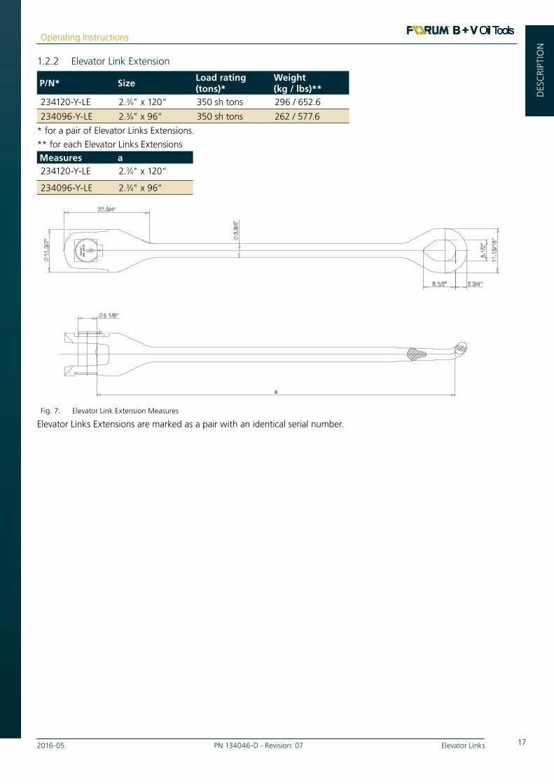
1.2.2 Elevator Link Extension
P/N* SizeLoad rating (tons)*
Weight (kg / lbs)**
234120-Y-LE 2.3⁄4" x 120“ 350 sh tons 296 / 652.6
234096-Y-LE 2.3⁄4" x 96“ 350 sh tons 262 / 577.6
* for a pair of Elevator Links Extensions.
** for each Elevator Links ExtensionsMeasures a234120-Y-LE 2.3⁄4" x 120“
234096-Y-LE 2.3⁄4" x 96“
5.1
/2"
11.
13/1
6"
3.
3/4"
11
.3/7
"
2.3/4" 8.1/2"
22.3/4"
Link Extension Lower Eye
5.1/8"
a
Main dimensions of Elevator Links Extension
- 234096-Y-LE: a=96"- 234120-Y-LE: a=120"
Fig. 7: Elevator Link Extension Measures
Elevator Links Extensions are marked as a pair with an identical serial number.

18 Elevator Links PN 134046-D - Revision: 07 2016-05
Operating Instructions
GEN
ERA
LG
ENER
AL
DESC
RIPTION
1.2.3 Elevator Link Connector
P/N SizeLoad rating (tons)
Weight (pair) (kg / lbs)
554150 2.3⁄4"- 3.1⁄2” 350 - 500 sh tons 313/ 690.6
Measures inch[mm]
A B C D E
554105 27.3 [695] 16.54[420] 16.93[430] 3.94[100] 5.24[133]
C
DE
A B
Fig. 8: Elevator Link Connector* Measures
Elevator Links Connectors are marked as a pair with an identical serial number. For differentiation the suffixes A and B are added to the serial number.
*Patent Pending

192016-05 PN 134046-D - Revision: 07 Elevator Links
Operating Instructions
GEN
ERA
LG
ENER
AL
BESC
HRE
IBU
NG
DES
CRI
PTIO
N
1.3 Optional AccessoriesTo ease the handling and to support the device functions following accessories are available from Forum B + V Oil Tools for the Links.
Please contact your local Forum B + V Oil Tools representant for detailed information.
- Grease Pump, manual PN 755667-3 Manual grease pump to apply grease on the device grease points.
Fig. 9: Manual Grease Pump
1.4 Recommended LubricantsForum B + V Oil Tools recommends use of the following lubricants for effective lubrication under various ambient conditions:Brand Name Temperature range RemarksFinke Aviaticon XRF
Low-Viscosity Grease-20. . +29 °C (-4. . +84.2 °F)
NLGI 0
Fuchs NESSOS SF0 EP grease for non-oil tight gear trains
-20. . +29 °C (-4. . +84.2 °F)
NLGI 0 DIN 51826 GPOF-25 DIN 51502 GPOF-25
* For temperatures above +30 °C (+86 °F) Forum B + V Oil Tools recommends using lubricants in consistency class NLGI 2.
INFO
The specified lubricants can be obtained through Forum B + V Oil Tools. Contact your local representative.

20 Elevator Links PN 134046-D - Revision: 07 2016-05
Operating Instructions
GEN
ERA
LG
ENER
AL
DESC
RIPTION
1.6 Machine MarkingsThe rating plate indicates all relevant information for distinct identification of the machine:
- Manufacturer
- Size
- Serial number (Link pair)
- ATEX classification
Always keep this information at hand for maintenance and repair work.
Example of Machine marking
Support data sticker on deviceThe email address of the manufacturer is given on the support sticker if service is required
1.5 Operational EnvironmentThe Links is designed and constructed for use in the drilling industry on ships and platforms.
The tool complies with the Machinery Directive
2006/42/EC.
The machine is approved for operation in explosion hazard areas. For machines containing any hydraulic powered parts, the directive 2014/34/EU “Equipment and protective systems in potentially explosive atmospheres” applies.
The corresponding ATEX certificates are present in the Data book.
The Classification according to CE (with reference to the ATEX guideline) is as followed:
II 2G IIB T5 for hydraulic and pneumatic tools
or
II 2G IIB T6 for manual tools
withCE- marking (with reference to the ATEX guideline)
Marking of the equipment for the Ex- range
II Equipment Group (II)2 Equipment Category
GFor explosive mixtures of air and combustible gases, mists or vapors (G)
IIB Categorie for GasesT5/T6 Temperature class

212016-05 PN 134046-D - Revision: 07 Elevator Links
Operating Instructions
SAFE
TYSAFETY

22 Elevator Links PN 134046-D - Revision: 07 2016-05
Operating Instructions
SAFETY
2 SafetyThe Links were designed and produced according to the state-of-the-art and in consideration of all required safety precautions.
Failure to observe the safety precautions and operating instructions specified in the present operating manual, can lead to hazardous situations when operating the machine. Notwithstanding the fact that it is not possible to completely exclude hazardous situations during operation.
Use the machine only for the intended purpose when it is in a technical safe state.
Rectify all faults immediately which could have a negative effect on the machine safety.
2.1 General Safety PrecautionsEnsure that work on the machine, particularly installation, maintenance and repair work, is performed only by personnel with the necessary qualifications and who are familiar with the associated risks (see Chapter „V Obligations of the Operating Company“ on page 7).
For safe and proper operation of the machine it is essential that all personnel working on the machine take the prescribed safety measures and observe the safety precautions specified in this operating manual.
The machine contains components subject to wear. After longer periods of operation the safety can be reduced due to wear. Service the machine regularly in compliance with the maintenance chart (see Chapter „6.2 Inspections“ on page 48) to ensure that all safety requirements are always fulfilled. Check the specified wear limits regularly. Replace worn or defective parts immediately with new parts.
If safe operation is no longer guaranteed, switch off the machine and secure it against being switched back on unintentionally. Advise the responsible service organization.
Rectify every fault, which affects the safety, immediately.
2.2 Safety EquipmentNever put the safety equipment out of operation or replace it with equipment not approved by Forum B + V Oil Tools. Failure to observe can lead to hazardous situations, for which Forum B + V Oil Tools cannot be held responsible.
Always keep all safety equipment in perfect condition and check regularly.
2.3 Safety Precautions
WarningReuse of safety components can cause accidents.
Never reuse safety-relevant parts (such as securing cables or plates, discs or washers).
Replace such components with new safety parts.
CautionThe operating company is responsible for ensuring safe and correct use of the equipment within the sense of the hazard and risk analysis.
The operating company is also obligated to issue and supervise observance of operating instructions on safe use as well as to observe the instructions in this operating manual.

232016-05 PN 134046-D - Revision: 07 Elevator Links
Operating Instructions
SIC
HER
HEI
TSA
FETY
2.5 Organizational MeasuresThe operating company is responsible for ensuring that all legally and officially prescribed approvals for operation of the machine are present in compliance with national laws and regulations.
The required personal protective equipment (see Chapter „VII Personal Protective Equipment (PPE)“ on page 10) must be provided by the company operating the machine.
All safety features present must be checked regularly in compliance with national and local requirements.
Warning signs and safety notices on the machine must be easily legible at all times and replaced as required.
The operating instructions must be kept so that they are available to those operating the machine at all times.
Personal Protective Equipment
The required Personal Protective Equipment (PPE) must be used when operating the machine. This is to be provided by the operating company.
The following PPE is recommended:
- Oil resistant protective clothing,
- Protective gloves,
- Eye protection,
- Safety shoes,
- Protective helmet.
All parts of the protective equipment must be checked regularly for damage in compliance with the specific national regulations and replaced as required.
2.4 Operating Manual and MachineThe safety precautions in this operating manual are indicted using standardized depictions and symbols. Chapter 1 describes general depiction of safety precautions.
Concrete examples of the symbols and terms used in this manual are explained below. These are used in the form shown wherever possible hazards are present.
DANGERSuspended load!
This indicates injury risks from transporting heavy components.
DANGERTipping hazard for components!
This indicates injury risks from tipping components.
WARNINGDanger of pinching/crushing hands!
This indicates injury risks from moving parts, which pose a hazard of pinching or crushing hands.
WARNINGDanger of pinching/crushing feet!
This indicates injury risks from moving parts, which pose a hazard of pinching or crushing feet.
WARNINGDanger of pinching/crushing body!
This indicates injury risks from moving parts, which pose a hazard of pinching or crushing the body.
CautionRisk of stumbling/tripping!
This symbol warns of tripping hazards, which can lead to stumbling resulting in injuries.
DANGERSuspended load!
This indicates injury risks from transporting heavy components.
24 Elevator Links PN 134046-D - Revision: 07 2016-05
Operating Instructions
SAFETY
2.6 Safety Precaution against
Remaining HazardsThis machine was designed and produced according to the state-of-the-art in consideration of the safety precautions specified in EC Directive 2006/42/EC on Machinery.
The machine may be used only for:
- Its intended purpose (see Chapter 1).
- When it is in a technically safe state.
Nevertheless it is not possible to completely exclude all hazardous situations which could arise when the machine is used. Reference is made to these remaining risks at the beginning of each chapter and at the corresponding points in the description and measures for avoiding these risks are explained.
WARNINGMechanically generated sparks
In the processing of incidents such as clamping components, sparks can be generated with the use of metal hammers.
- The use of metallic hammers in hazardous areas has therefore be prohibited by the operating company.
» For loosening of clamping components only non-metallic (plastic) hammer, which are approved for use in hazardous areas, may be used.
INFOThe operating company is responsible for ensuring that all personnel working on the machine is familiar with the remaining risks and observe the appropriate safety precautions.
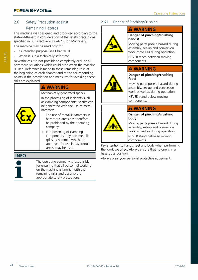
2.6.1 Danger of Pinching/Crushing
WARNINGDanger of pinching/crushing hands!
Moving parts pose a hazard during assembly, set-up and conversion work as well as during operation.
NEVER reach between moving components.
WARNINGDanger of pinching/crushing feet!
Moving parts pose a hazard during assembly, set-up and conversion work as well as during operation.
NEVER stand below moving components.
WARNINGDanger of pinching/crushing body!
Moving parts pose a hazard during assembly, set-up and conversion work as well as during operation.
NEVER stand between moving components.
Pay attention to hands, feet and body when performing the work specified. Always ensure that no one is in a hazardous position.
Always wear your personal protective equipment.

252016-05 PN 134046-D - Revision: 07 Elevator Links
Operating Instructions
SIC
HER
HEI
TSA
FETY
2.6.2 Human ErrorIgnorance of hazards, inattentiveness and limited reactions can lead to hazard situations while working with the Links.
Safe Work1. All personnel working on the machines are
responsible for paying attention to their colleagues.
2. Consumption of alcohol and drugs is prohibited.
3. Work on the Links is not permissible after taking medication which reduces reactions.
4. AT LEAST visual contact must exist between the operator in the doghouse and the personnel at the Links, to allow communication via hand signals.
5. The personal protective equipment must always be kept and used in perfect condition.
6. All personnel working on the Links, must be familiar with and observe the safety precautions in this instruction manual and on the machine.
7. The instructions for handling and maintenance intervals specified in this operating manual must be observed.
8. Keep a copy of this operating manual in the vicinity of the machine, where it is accessible at all times.
2.7 Accidents, Fire
Basic rules in event of accidents or fire1. Move accident victims out of hazard area and
switch off machine immediately.
2. Administer first-aid.
3. Alarm rescue services and fire department immediately and inform supervisor.
In addition all national, local and internal plant regulations for fire fighting in explosion hazard areas apply.
26 Elevator Links PN 134046-D - Revision: 07 2016-05
Operating Instructions
SAFETY

272016-05 PN 134046-D - Revision: 07 Elevator Links
Operating Instructions
TRA
NSP
ORT
/ SE
T-U
P
TRANSPORT / SET-UP

28 Elevator Links PN 134046-D - Revision: 07 2016-05
Operating Instructions
TRA
NSPO
RT/ SETU
P
3 Transport / Setup
Ensure that setup and installation work are accomplished only by sufficiently qualified and trained personnel.
Read these instructions carefully before setting up the machine and putting it into service.
3.1 DeliveryThe Links and all accessory parts are shipped in a transport crates. Instructions for safe transport are attached to the transport crates. Transport the packed machine as specified in these instructions.
3.1.1 Scope of Delivery
INFOThe contract documents and shipment papers specify the precise scope of delivery. Check these documents carefully on delivery. In the event of any discrepancies please contact the Forum B + V Oil Tools representative specified in Chapter „Contact worldwide“ on page 11 immediately.
The scope of delivery includes all components required for the intended operation of the Elevator Links as described in Chapter „Description“ on page 14
3.1.2 Unpacking and Disposal of Packing MaterialRemove the transport packaging and transport aids before hoisting the machine.
NOTEDo not remove transport retainers.
The transport retainers should be removed only at the installation site just before startup.
Check scope of delivery.1. Is any transport damage visible?
2. Is the shipment complete? Compare the scope of delivery with the specifications in the shipping documents.
If theLinks has been damaged during transport or the shipment is incomplete, please notify the manufacturer immediately (see Chapter „IX Contact worldwide“).
Dispose of the packaging material ecologically in compliance with all applicable regulations.
3.1.3 Intermediate StorageIf intermediate storage of the Links is necessary, observe the following:
• Leave the machine it its transport packaging. This provides sufficient protection against external influences.
• Secure the machine to prevent it from slipping or falling due to motion.
292016-05 PN 134046-D - Revision: 07 Elevator Links
Operating Instructions
TRA
NSP
ORT
/ SE
TUP
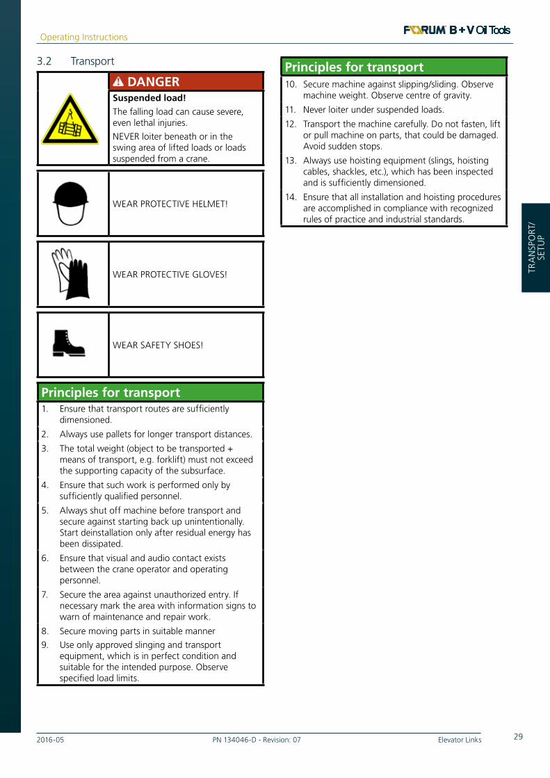
3.2 Transport
DANGERSuspended load!
The falling load can cause severe, even lethal injuries.
NEVER loiter beneath or in the swing area of lifted loads or loads suspended from a crane.
WEAR PROTECTIVE HELMET!
WEAR PROTECTIVE GLOVES!
WEAR SAFETY SHOES!
Principles for transport1. Ensure that transport routes are sufficiently
dimensioned.
2. Always use pallets for longer transport distances.
3. The total weight (object to be transported + means of transport, e.g. forklift) must not exceed the supporting capacity of the subsurface.
4. Ensure that such work is performed only by sufficiently qualified personnel.
5. Always shut off machine before transport and secure against starting back up unintentionally. Start deinstallation only after residual energy has been dissipated.
6. Ensure that visual and audio contact exists between the crane operator and operating personnel.
7. Secure the area against unauthorized entry. If necessary mark the area with information signs to warn of maintenance and repair work.
8. Secure moving parts in suitable manner
9. Use only approved slinging and transport equipment, which is in perfect condition and suitable for the intended purpose. Observe specified load limits.
Principles for transport10. Secure machine against slipping/sliding. Observe
machine weight. Observe centre of gravity.
11. Never loiter under suspended loads.
12. Transport the machine carefully. Do not fasten, lift or pull machine on parts, that could be damaged. Avoid sudden stops.
13. Always use hoisting equipment (slings, hoisting cables, shackles, etc.), which has been inspected and is sufficiently dimensioned.
14. Ensure that all installation and hoisting procedures are accomplished in compliance with recognized rules of practice and industrial standards.

30 Elevator Links PN 134046-D - Revision: 07 2016-05
Operating Instructions
TRA
NSPO
RT/ SETU
P
3.2.1 Weights
- Detailed weight specifications are given in the Chapter "Technical Data"
3.2.2 Transport to Installation Site
Hoist the machine safely1. Attach the Links only at the attachment points
provided for transport.
2. Only use approbate lifting material with a load carrying capacity suitable to the weight of the elevator / spider.
3. Attach the hoisting ropes so that they are tensioned straight without kinks.
4. Use hoisting cables and load hooks with sufficient supporting capacity.
1. Fasten the lifting material on Links lifting points.
2. Lift the Links slightly to tension the lifting material.
WARNING Danger of collision with swinging loads! Ensure that no one is present in the swing range of the machine.
3. Lift the Links.
4. Move the Links to the installation location.
5. Set the Links down carefully on a suitable surface.
WARNING Potential Hazards: - Being pinched by the elevator links while attaching elevators (or attaching elevator links to the hook). - Being struck by the elevators. Consequences: » Use proper hand placement when attaching elevator links. » Ensure workers stand away from swing-path of the elevators and elevator links. » Use lifting equipment and limit manual positioning of elevators. » Use proper mounting and lifting procedures.
3.3 Setup
DANGERSuspended load!
The falling load can cause severe, even lethal injuries.
NEVER loiter beneath or in the swing area of lifted loads or loads suspended from a crane.
WEAR PROTECTIVE HELMET!
WEAR PROTECTIVE GLOVES!
WEAR SAFETY SHOES!
The Links is completely preassembled before shipment, so that it can be installed immediately after unpacking at the installation site.

312016-05 PN 134046-D - Revision: 07 Elevator Links
Operating Instructions
CO
MM
ISSI
ON
ING
/ O
PER
ATI
ONCOMMISSIONING /
OPERATION
32 Elevator Links PN 134046-D - Revision: 07 2016-05
Operating Instructions
OPER
ATIO
N
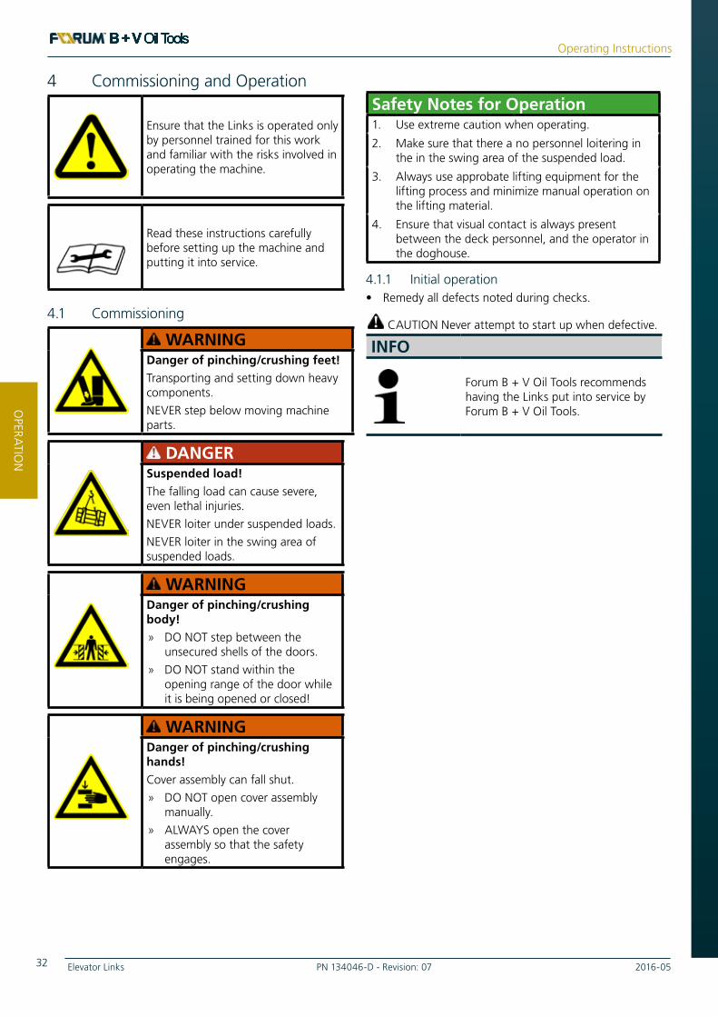
4 Commissioning and Operation
Ensure that the Links is operated only by personnel trained for this work and familiar with the risks involved in operating the machine.
Read these instructions carefully before setting up the machine and putting it into service.
4.1 Commissioning
WARNINGDanger of pinching/crushing feet!
Transporting and setting down heavy components.
NEVER step below moving machine parts.
DANGERSuspended load!
The falling load can cause severe, even lethal injuries.
NEVER loiter under suspended loads.
NEVER loiter in the swing area of suspended loads.
WARNINGDanger of pinching/crushing body!
» DO NOT step between the unsecured shells of the doors.
» DO NOT stand within the opening range of the door while it is being opened or closed!
WARNINGDanger of pinching/crushing hands!
Cover assembly can fall shut.
» DO NOT open cover assembly manually.
» ALWAYS open the cover assembly so that the safety engages.
Safety Notes for Operation1. Use extreme caution when operating.
2. Make sure that there a no personnel loitering in the in the swing area of the suspended load.
3. Always use approbate lifting equipment for the lifting process and minimize manual operation on the lifting material.
4. Ensure that visual contact is always present between the deck personnel, and the operator in the doghouse.
4.1.1 Initial operation• Remedy all defects noted during checks.
CAUTION Never attempt to start up when defective.
INFO
Forum B + V Oil Tools recommends having the Links put into service by Forum B + V Oil Tools.

332016-05 PN 134046-D - Revision: 07 Elevator Links
Operating Instructions
BED
IEN
UN
GO
PER
ATI
ON
4.1.1.2 Mounting Elevator Links to the
Top Drive System (Hook)1. Position the Elevator Links in a approbate mounting
position using lifting equipment and ropes.
2. The Top Drive System with the hook (1) must be driven downwards until the hook in a position that the upper attachment ear (2) of the Elevator Links can be mounted.
3. Mount the Elevator Links (2) to the hook (1).
4. Move the Top Drive System slowly upwards. Use rope to stabilize the Elevator Links to prevent swinging.
► The Elevator Links are mounted to the hook. An elevator can now be installed to the Elevator Links.
INFOMounting an elevator to the Elevator Links is part of the operation manual of the elevator. Please refer to the operation manual of the elevator/spider in order to mount the elevator/spider.
Fig. 10: Elevator Links Hook and elevator connection
4.1.1.1 Mounting the Elevator Links
DANGERSuspended load!
The falling load can cause severe, even lethal injuries.
» NEVER loiter under suspended loads.
» NEVER loiter in the swing area of suspended loads.
» Ensure workers stand away from swing-path of the elevators and elevator links.
WARNINGPotential Hazards:
- Being pinched by the elevator links while attaching elevators (or attaching elevator links to the hook).
- Being struck by the elevators.
» Use proper hand placement when attaching elevator links.
» Use lifting equipment and limit manual positioning of elevators.
» Use proper mounting and lifting procedures.
WEAR PROTECTIVE HELMET!
WEAR PROTECTIVE GLOVES!
WEAR SAFETY SHOES!
2
1

34 Elevator Links PN 134046-D - Revision: 07 2016-05
Operating Instructions
OPER
ATIO
N
1. Move the Top Drive System (Hook and Elevator Links) downwards until the lower lifting eyes of the Elevator Links touch the rig floor.
CAUTION Stabilize the Elevator Links while moving with ropes to prevent swinging of the Elevator Links.
2. Position the fork opening of the Elevator Links Extensions in the lower Lifting opening of the Elevator Links (1).
3. Secure Elevator Links Extensions position by placing the bolt (2) in the connection bore.
4. Tighten and secure the bolt (2) with the securing plate and the screws (3).
CAUTION Make sure that the securing plate is positioned in the bearing.
Fig. 11: Mounting the Elevator Link Extension to theElevator Links
5. Repeat Steps 2. - 4. for the remaining Elevator Link.
► The Elevator Links Extensions are installed and can be used with an Elevator/Spider .
4.1.1.3 Mounting the Elevator Link
Extension to the Elevator Links
DANGERSuspended load!
The falling load can cause severe, even lethal injuries.
» NEVER loiter under suspended loads.
» NEVER loiter in the swing area of suspended loads.
» Ensure workers stand away from swing-path of the elevators and elevator links.
WARNINGPotential Hazards:
- Being pinched by the elevator links while attaching elevators (or attaching elevator links to the hook).
- Being struck by the elevators.
» Use proper hand placement when attaching elevator links.
» Use lifting equipment and limit manual positioning of elevators.
» Use proper mounting and lifting procedures.
WEAR PROTECTIVE HELMET!
WEAR PROTECTIVE GLOVES!
WEAR SAFETY SHOES!
12
3

352016-05 PN 134046-D - Revision: 07 Elevator Links
Operating Instructions
BED
IEN
UN
GO
PER
ATI
ON
4.1.1.4 Mounting the Elevator Link
Connectors to the Elevator Links
DANGERSuspended load!
The falling load can cause severe, even lethal injuries.
» NEVER loiter under suspended loads.
» NEVER loiter in the swing area of suspended loads.
» Ensure workers stand away from swing-path of the elevators and elevator links.
WARNINGPotential Hazards:
- Being pinched by the elevator links while attaching elevators (or attaching elevator links to the hook).
- Being struck by the elevators.
» Use proper hand placement when attaching elevator links.
» Use lifting equipment and limit manual positioning of elevators.
» Use proper mounting and lifting procedures.
WEAR PROTECTIVE HELMET!
WEAR PROTECTIVE GLOVES!
WEAR SAFETY SHOES!
Installation tasks
1. Prepare the Link Connector for installation by fastening a suitable load ring q in the intended thread hole on the Link Connector body.
2. Attach Link Connector to crane.
3. Loose upper screws, Nord Lock washer and pin bracket in link block w and push the link block pin e out of the Link Connector.
CAUTION Link block r may swing open without attention! Don’t stay in the swing area of the link block while removing the link block pin.
4. Open the link block r.5. Guide the Link Connector by means of a crane to the
lower elevator Link eye t.6. Charge Link Connector to Link.
7. Close the link block and re-install block pin.
Fig. 12: Mounting the Elevator Link to upper Connector*
8. Position and attach securing plate with two M16 screws with Nord Lock washers. Fasten screws with torque 210 Nm.
9. Lift Link Connector slowly with Elevator Link
q
w
e
r
t
*Patent Pending

36 Elevator Links PN 134046-D - Revision: 07 2016-05
Operating Instructions
OPER
ATIO
N
10. Repeat Steps 3. - 7. for Link Connector Link connection.
Fig. 13: Mounting the Elevator Link to the lower Connector*s
11. Guide second link in lower Connector.
12. Close and secure lower connector.
13. Check upper and lower Link Block are properly closed and secured.
► The Elevator Links Connectors are installed and can be used with an Elevator/Spider.
q
w
e
r
t
*Patent Pending

372016-05 PN 134046-D - Revision: 07 Elevator Links
Operating Instructions
BED
IEN
UN
GO
PER
ATI
ON
4.1.2 Installation ChecklistsPrior to use following checks must be carried out :
4.1.3 Installation Checklist Links Extension
OK ⎕ Make sure the bolt is in secured fitting.
OK ⎕ Make sure the Nord Lock -Washer are placed.
OK ⎕ Make sure the securing plate is installed and the screws are tightened.
4.1.4 Installation Checklist Link Connector
OK ⎕ Make sure the bolts are in secured fitting.
OK ⎕ Make sure the Nord Lock -Washer are placed.
OK ⎕ Make sure the securing plates are installed and the screws are tightened.

38 Elevator Links PN 134046-D - Revision: 07 2016-05
Operating Instructions
OPER
ATIO
N
4.2 Operation
WARNINGDanger of pinching/crushing body!
The body may fall shut.
» DO NOT step between the unsecured shells of the open body.
» DO NOT remove the spreading tool BEFORE closing the body and securing it with the hinge pin.
WARNINGDanger of pinching/crushing feet!
Transporting and setting down heavy components.
NEVER step below moving machine parts.
Safety precautions1. Be particularly careful in during operation.
2. Ensure that visual contact is always present between the deck personnel, and the operator in the doghouse.
Operational Safety1. Do not touch the Links while in operation.
2. All screw retainers present.
3. Make sure that ALL hydraulic lines are isolated before any work is carried out in the Links.
4. It is recommended to have the Links operated by the driller.
.

392016-05 PN 134046-D - Revision: 07 Elevator Links
Operating Instructions
SERV
ICE
SERVICE

40 Elevator Links PN 134046-D - Revision: 07 2016-05
Operating Instructions
SERVIC
E
5.2 Repair
5.2.1 Repair by CustomerIt is only permissible for the customer/company operating the machine to replace defective parts with OEM (Original Equipment Manufacturer) parts approved by Forum B + V Oil Tools in conformance with the present operating instructions.
Use of parts not approved by Forum B + V Oil Tools voids the guarantee.
5.2.2 Repair by ManufacturerEnsure that any repair work required on the Links is performed only by Forum B + V Oil Tools or an authorized service company.
INFO
Please contact the Forum B + V Oil Tools Technical Support or one of the authorized service companies specified in Chapter 1.9 to perform repair or maintenance work.
5.2.3 Securing Screws with Nord Lock washersNord Lock bolt securing systems use geometry to safely lock bolted joints in the most critical applications. The key is the difference in angles. Since the cam angle „∂“ is larger than the thread pitch „ß“, the pair of washers expands more than the corresponding pitch of the thread. Any attempt from the bolt/nut to rotate loose is blocked by the wedge effect of the cams.
When the pushed movements of the device will get in contact with the under surface of the securing plate, this surface contact will secure the plate and prevents any motion in the axial direction.
Fig. 14: Nord Lock Washer principle illustration
Fig. 15: Nord Lock Washer detailed illustration
5 Service
5.1 MalfunctionIf a malfunction occurs or the Links does not operate as expected, trouble-shoot as follows:
If the cause of the malfunction cannot be determined and remedied, contact Forum B + V Oil Tools Technical Support.
1. Check hydraulic connections and hydraulic lines.
2. Check whether the hydraulic unit is switched on.
3. Check whether the Slip,and Slip Adapter have been installed for the size/type of pipe used.
4. Check for proper lubrication of the Links.
5. Check feedback (from slip) for proper function.
6. Collect all information on the malfunction and define the problem.
7. Attempt to find a quick solution to the problem.
8. Check the last changes/modifications.
9. Isolate the problem.
10. Replace any defective components.
INFO
In the event of problems, which cannot be remedied with the aid of this manual, please contact the Forum B + V Oil Tools Technical Support or one of the authorized service companies specified in Chapter 1.9.

412016-05 PN 134046-D - Revision: 07 Elevator Links
Operating Instructions
SERV
ICE
5.3 Drawing, Parts List and Spare Parts
5.3.1 Contact to Parts Department
INFOPlease contact the Forum B + V Oil Tools Technical Support or one of the authorized service companies specified in Chapter 1.9 to order replacement parts or in the event of any questions.
Tightening torques for Nord Lock lock washers Several Nord Lock bolt securing systems are used on the Links to generate safely lock bolted joints. Regarding the fact that different sizes and metric grades are applied detailed information from Nord Lock is given in the annex (refer to annex „I Nord Lock Washer (excerpt from Third Party Product information)“ on page 67) to generate safe maintenance by the user.
The metric grade and make of the bolt can be seen on top of the bolt/nut.
Fig. 16: Nord Lock Marking
On Forum B + V Oil Tools Pipe handling Equipment the metric grades 8.8, 10.9 and 12.9 are used and the tightening torques can be found in the „a. Torque Guidelines“ on page 69.
WARNING Please pay extra attention to the method of tightening as the tightening torques may vary on the methods.
INFOAs a result from tests the NORD LOCK washers were safely secured even after reuse 30 times. Only a limited part of the clamp load was lost due to normal settlements between contact surfaces. The cam edges of the washers got rounded off but were still intact after the reuse test.
The best thing to do is to make ocular inspection of the washers during every maintenance.
Make sure that the cams (cam tops) look good and that the teeth are not worn off. Lubricate the joint and the mating surfaces if possible so that the friction conditions do not change. When reassembling, care should be taken that the two washer halves are mated correctly.
If all these criteria are met, the washers can be safely reused.

42 Elevator Links PN 134046-D - Revision: 07 2016-05
Operating Instructions
SERVIC
E
5.3.2 554150 Link Connector
SWCAD
namedayengineering changech.no
The present document is the property of
FORUM B + V Oil Tools GmbH
This document or any part there of must neither beused, reproducted, communicated, published, normade known third parties in any other way, unless the corresponding authorisation has been previously
obtained from FORUM B+V writing.
dayFormat kg
part nameWeightScale
normcheck.drawn
Material
AUTHORIZED MANUFACTURER
Hamburg-GermanyOil Tools GmbH
sh.
sheetpart no.
nameSurfaceDIN ISO
1302 500 short tons/set11.02.201615.03.2016
F.StoldtV.Eslava
ToleranceDIN ISO2768-m
1:5 A2 313.23
Set of Link Connector
554150C:\PDMWE\PDM\Links\Link Connector\500\
21
1
2
3
46
5
R62,5 ±2,5
R62
,5 ±2
,5
A
A In diesem BereichRadius R62.5 und R65 prüfen
In diesem Bereich RadiusR62.5 und R65 prüfen
137
,5 ±2
1
37,5
±2
R65
±2,5
R65
±2,5
A-A (1 : 8)
An dem markierten Bereichen in der unteren Ansicht muss während der Montageder Radius R62.5 und R65 geprüft und ggf. durch schleifen angepasst werden.
Item Each Unit Part No Description DIN-Standard Material Weight
6 16 pcs 792106 Washer NL16 St 0.01
5 16 pcs 710541 Screw DIN 933 - M16x35 8.8 galzn 0.09
4 8 pcs 554154 Securing Plate S355J2 0.38
3 8 pcs 554153 Link Block PinNach
Spezifikation "SPECBolzen
850"3.05
2 4 pcs 554152 Link Block 34CrNiMo6V 19.23
1 2 pcs 554151B-BF S-Frame S690QL 103.61
H
G
F
E
D
C
B
A
1 2 3 4 6 7 8 9 10
10987654321
E
F
G
H
A
B
C
D
5
Fig. 17: 554150 Link Connector*
Part lists 554150No. Qty. Part No. Description1 2 554151B-BF S-Frame
2 4 554152 Link Block
3 8 554153 Link Block Pin
4 8 554154 Securing Plate
5 16 710541 Screw
6 16 792106 Washer
554150-RSP Recommended Spare part for 1 YearNo. Qty. Part No. Description1 1 554152 Link Block
2 2 554153 Link Block Pin
3 1 554154 Securing Plate
4 16 710541 Screw
5 16 792106 Washer
*Patent Pending

432016-05 PN 134046-D - Revision: 07 Elevator Links
Operating Instructions
SERV
ICE
5.3.3 Link Extension
Part No. Description234120-Y-LE Link Extension 2.3⁄4‘‘ x 120‘‘
234096-Y-LE Link Extension 2.3⁄4‘‘ x 96‘‘
Fig. 18: Isometric view Link Extension
1
3
5
4
2
6

44 Elevator Links PN 134046-D - Revision: 07 2016-05
Operating Instructions
SERVIC
E
Part lists / Spare parts 234120-Y-LENo. Qty. Part No. Description1 1 234120-LE-BF Forum B + V Oil Tools Type Set of Elevator Links
2 2 234001-1 Link Connector Bolt
3 2 554105-5 Securing Plate
4 4 234007 Screw
5 4 792171 Washer
6 2 70064 Grease Fitting
Part lists / Spare parts 234096-Y-LENo. Qty. Part No. Description1 1 234096-LE-BF Forum B + V Oil Tools Type Set of Elevator Links
2 2 234001-1 Link Connector Bolt
3 2 554105-5 Securing Plate
4 4 234007 Screw
5 4 792171 Washer
6 2 70064 Grease Fitting

452016-05 PN 134046-D - Revision: 07 Elevator Links
Operating Instructions
INSP
ECTI
ON
/ M
AIN
TEN
AN
CE
INSPECTION / MAINTENANCE

46 Elevator Links PN 134046-D - Revision: 07 2016-05
Operating Instructions
INSPEC
TION
/ M
AIN
TENA
NC
E
6 Inspection / Maintenance
Ensure that setup and installation work are accomplished only by sufficiently qualified and trained personnel.
Read these instructions carefully before setting up the machine and putting it into service.
WEAR EYE PROTECTION!
WEAR PROTECTIVE HELMET!
WEAR PROTECTIVE GLOVES!
WEAR SAFETY SHOES!
Instructions for inspection and maintenance1. In the event of visible damage or excessive
wear contact the Forum B + V Oil Tools Service Department or an authorized repair company.
2. Ensure that all other maintenance work is performed only by personnel trained for this work and familiar with the risks involved in operating the machine.
3. Ensure that all repair work not performed by Forum B + V Oil Tools is nevertheless accomplished in compliance with the manufacturer's specifications and instructions.
Instructions for inspection and maintenance4. Small cracks and irregularities, which do not affect
the safety or proper operation of the Links can be removed by grinding (see Critical Areas).
5. Provide for sufficient lighting at the workplace.
6. Ensure that the Links is set down on a good supporting surface so that it cannot tip.
7. After repair always check the repaired part in a suitable manner to ensure that the defect has been remedied.
WARNING
Welding on Elevator Links is prohibited!

472016-05 PN 134046-D - Revision: 07 Elevator Links
Operating Instructions
INSP
EKTI
ON
UN
DW
ART
UN
GIN
SPEC
TIO
N /
MA
INTE
NA
NC
E
6.1 Lubrication
WARNINGLubricants can pose a health hazard!
Lubricants irritate skin and eyes.
Avoid contact with lubricants.
WEAR EYE PROTECTION!
WEAR PROTECTIVE GLOVES!
The Links are supplied with lubricating grease manually by a grease gun through lubrication nipples.
When the tool is in use, the following lubrication procedure should be performed daily, or as inspection indicates.
6.1.1 Lubrication stepsLubricate the hinge pin, the pins for door cylinder and feedback valve at the grease nipple with a hand grease gun until the grease comes out uniformly from the openings.
Lubricate the springs of the latch system by applying grease with a brush.
Lubricate the catch pin and pins for latch cylinder by applying a uniform film of lubricant on the surface with a brush.
Lubricate the latch handle pin and the latch system. To do this, take care not to pull the bolts out fully and with a brush apply a uniform film of lubricant on the surface.
6.1.2 Lubrication Points Elevator Link ExtensionLubrication Point 1 must be lubricated at least once every day with one of the specified lubricants. The lubrication requirement can be higher depending on the conditions of use.
Fig. 19: Lubrication Points Elevator Link Extension
SWCAD
6
2
1
3
5
4
M 1:10
6 1 pcs 70064 Grease Fitting DIN 71412 - R1/8 St galzn 0.01
5 2 pcs 792108 Washer NL20 St 0.01
4 2 pcs 735122 Screw DIN 933 M20x50 8.8 0.20
3 1 pcs 554105-3 Securing Plate S235JR 1.54
2 1 pcs 234001 Link Connector Bolt 34CrNiMo6V 29.88
1 1 pcs 234120-LE-BF
B+V Type Set of Elevator Links,
B+V techn. spez.
34CrNiMo6V
287
Item Each Unit Part No Description DIN-Standard Material Weight
z Rz 16
y Rz 25
x Rz 63
w Rz 100
day name
ToleranceDIN ISO
SurfaceDIN ISO
part no. sheet
sh.
BLOHM & VOSSOil Tools GmbH
Hamburg-Germany
AUTHORIZED MANUFACTURER
Material
drawncheck.norm
Scale Weight
part name
The present document is the property of
BLOHM & VOSS Oil Tools GmbHThis document or any part there of must neither beused, reproducted, communicated, published, normade known third parties in any other way, unlessthe corresponding authorisation has been previouslyobtained from Blohm & Voss writing.
namedayengineering changech.no
kgFormat
11
C:\PDMWE\PDM\Links\234000-Link Extension\
234000-LE
Link Extension
479.06A21:5
2768-m 1302
O. StromannMarco Lau
12.06.201312.06.2013
350t
q
6.1.3 Lubrication IntervalsAreas of the machine marked with the plate GREASE DAILY must be lubricated at least once each day with one of the specified lubricants. The lubrication requirement can be higher depending on the conditions of use.
INFO
The specified lubricants can be obtained through Forum B + V Oil Tools. Contact your local representative.
Tools
- Grease Gun
Fig. 20: Recommended Grease Gun
Fig. 21: Instructions: Lubricate at Least Once Daily (P/N 671642)

48 Elevator Links PN 134046-D - Revision: 07 2016-05
Operating Instructions
INSPEC
TION
/ M
AIN
TENA
NC
E
6.2 InspectionsPerform inspections in compliance with API RP 8B at specified intervals and in inspection categories. Otherwise the frequency of required inspections is dependent on the conditions of use of the machine.
Shut off the machine and disconnect the hydraulic/Pneumatic connections before performing an inspection.
Before inspection remove all foreign material such as dirt, paint, lubricants, oil, abrasion, etc. from the affected parts. Use suitable methods such as stripping off paint, steam cleaning, sand blasting, etc.
After an operating inspection the scope and results of the tests performed should be documented.
Periodic inspections and inspections following critical assignments should be accomplished at the operating location by the operators under the supervision of a supervisor.
In the event of cracks, excessive wear, etc. contact Forum B + V Oil Tools or an authorized service company.
INFOThe specified maintenance intervals are recommended for the Links during its service life. The necessity of inspections depends primarily on the following conditions:
- Ambient conditions
- Load cycles
- Regulatory requirements
- Period of use
- Tests
- Repairs
- Overhauls
6.2.1 Inspection of Hydraulic EquipmentCheck the hydraulic equipment daily for leakage. If unacceptably high leakage occurs internally or externally contac t Forum B + V Oil Tools or an authorized service company.
6.2.2 Inspection Following Critical LoadsPerform an inspection IMMEDIATELY following any critical or unexpected loads. Critical loads could be:
- Loads resulting from shock when the drill pipe wedges,
- Pulling wedged drill strings,
- Holding heavy drill pipes / drill strings
- Jarring
- Operation at very low ambient temperatures (<-20 °C / -4 °F).
6.2.3 Inspection Following RemovalGenerally the Links should be inspected immediately before it is taken out of service temporarily or stored.
Moreover it should be inspected before putting back into service.
- It is necessary to disassemble the Links in an appropriately equipped workshop to check for excessive wear, deformation, cracks and other damage.
- Perform repair work only in compliance with the manufacturer's recommendations. These are available from Forum B + V Oil Tools.
- Ensure that welding work on cast parts is accomplished only by Forum B + V Oil Tools or an authorized service company in compliance with the welding specifications issued by Forum B + V Oil Tools.
- If the field inspection indicates that further inspection work is required, remove the Links and have it inspected in an appropriately equipped workshop.
- Check carefully for visible wear and material fatigue.
Inspection Intervals
Category Interval Preparatory measures
I Daily - Links on rigII Weekly - Links on rig
III Semi-annually - Links on rig - Links partly dismantled
IV Every 1 years - Links on rig - Links partly dismantled

492016-05 PN 134046-D - Revision: 07 Elevator Links
Operating Instructions
INSP
EKTI
ON
UN
DW
ART
UN
GIN
SPEC
TIO
N /
MA
INTE
NA
NC
E
6.3.3 Inspection Category IIICategory III includes additional tests not included in Category II inspections.
Scope/Prerequisites
- Before inspection remove all foreign material such as dirt, paint, lubricants, oil, abrasion, etc. from the affected parts. Use suitable methods such as stripping off paint, steam cleaning, sand blasting, etc.
Procedure:
- Non-destructive testing (NDT) is required in critical areas as well as removal of certain parts to determine the wear limits according to the specified tolerances.
6.3.4 Inspection Category IVIn addition to the inspections in Category III, Category IV includes removal of all primary, load-bearing parts for non-destructive testing (NDT).
Scope/Prerequisites
- Appropriately equipped workshop
- Remove all primary load-bearing parts or parts critical for operation to such an extent that complete inspection is possible.
- Inspect all parts for excessive wear, cracks, deformation and other damage
- in critical areas as well as removal of certain parts to determine the wear limits according to the specified tolerances
Procedure:
- Ensure that all tests are performed according to the manufacturer‘s specifications.
- Before inspection remove all foreign material such as dirt, paint, lubricants, oil, abrasion, etc. from the affected parts. Use suitable methods such as stripping off paint, steam cleaning, sand blasting, etc.
6.3 Inspection CategoriesAlways perform a complete inspection according to the instructions in Categories III or IV before AND after critical loads (see Chapter ).
INFO
Inspection categories acc. to API 8B
6.3.1 Inspection Category IThis category consists of observing the machine during operation for signs of inadequate operation.
Scope/Prerequisites
- During operation check the machine daily for visible damage such as cracks, breaks, loose connecting elements and obvious signs of wear.
Procedure:
- Visual check.
- Put all parts indicating such signs out of service and check for proper function.
- Ensure that this check is accomplished by a person with appropriate technical knowledge.
6.3.2 Inspection Category IICategory II includes additional tests not included in Category I inspections.
Scope/Prerequisites
- Check for signs of corrosion, deformation, loose or missing parts, aging processes, proper lubrication, externally visible cracks and adjustment work.
Procedure:
- Category II inspections may require removal of certain parts to assess the wear limits according to the specified tolerances.

50 Elevator Links PN 134046-D - Revision: 07 2016-05
Operating Instructions
INSPEC
TION
/ M
AIN
TENA
NC
E
6.4 Inspection Intervals and inspection tasks
Pos. Task / Interval Daily Weekly 6 Monthly 1 Year
1 Ongoing observation ' ' ' '2 Grease all grease points and check state of lubrication ' ' ' '3 Check completeness and condition
of warning labels and plates 4 Check function ' ' ' '5 Check for loose items, especially on:
shafts, bolts, retainers, screws, nuts, washers, springs, lock wire
" ' ' '
6 Visual check for cracks, elongation, change, corrosion on all parts. "
7 Check parts for wear according to allowable tolerances. " " '8 Perform NDT on al primary-load-carrying components and
all critical parts. " " " ' Necessary Safety Task! Take out service for repair if NOK! " Not necessary

512016-05 PN 134046-D - Revision: 07 Elevator Links
Operating Instructions
INSP
EKTI
ON
UN
DW
ART
UN
GIN
SPEC
TIO
N /
MA
INTE
NA
NC
E
Check Lists for Inspections
INFOThe following check lists serve as copy templates for inspections to be performed in compliance with API 8B and are required to file performed inspections as defined in the user manual .
Machine model
Serial number
Part number
Ensure that maintenance work is accomplished only by sufficiently qualified and trained personnel.
Elevator Links Links Connector Links Extension
Inspection Category I
Date / Place of Inspection Checked
OK NOK
Name of Inspection Operator /Supervisor
Sign.
Remarks:
Inspection Category II
Date / Place of Inspection Checked
OK NOK
Name of Inspection Operator /Supervisor
Sign.
Remarks:
Inspection Category III
Date / Place of Inspection Checked
OK NOK
Name of Inspection Operator /Supervisor
Sign.
Remarks:
Inspection Category IV
Date / Place of Inspection Checked
OK NOK
Name of Inspection Operator /Supervisor
Sign.
Remarks:

52 Elevator Links PN 134046-D - Revision: 07 2016-05
Operating Instructions
INSPEC
TION
/ M
AIN
TENA
NC
E
h
dg
f e
c
a
1.3/4"
2.1/4"-3.1/2"
4.3/4"
5.1/2"
6.1/2"
UPPER EYE LOWER EYE
b xleng th as ordered
Fig. 23: Measure points wear Elevator Links
6.4.1 Measuring of wearIt is obvious that a visual inspection is not enough to check a lifting device like the Links. To measure link ears it is necessary to use callipers and a ruler.
Significant wear is restricted to the top link ear, it is here that the measurement is taken.
Pins, bolts and socket holes are not normally measured for wear in the field. When it becomes apparent that the pins and bolts have more tolerances, the Links should be dismantled for general engineering check up.

532016-05 PN 134046-D - Revision: 07 Elevator Links
Operating Instructions
INSP
EKTI
ON
UN
DW
ART
UN
GIN
SPEC
TIO
N /
MA
INTE
NA
NC
E
6.4.2 Wear table Elevator Links
Type Series wear table
1.3⁄4-150 tons 2.1⁄4-250 tons 2.3⁄4-350 tons 3.1⁄2”-500 tons 4.3⁄4”-750 tonsNew max. Wear New max. Wear New max. Wear New max. Wear New max. Wear
Dimension f [in] 3.3 ⁄4 3.3 ⁄8 5 4.3⁄4 5.3 ⁄8 4.3 ⁄4 6.1⁄16 5.5 ⁄8 4.3 ⁄4 4.3 ⁄8
[mm] 95.2 85.7 127.0 120.7 136.5 120.7 154.0 142.9 120.6 111.1
Dimension x [in] 2.1⁄4 1.5 ⁄8 2.2 ⁄5 2.1⁄8 2.7⁄8 2.5 ⁄8 3.1⁄2 3.1⁄4 4.3 ⁄4 4.3 ⁄8
[mm] 57.1 46.8 61.0 54.0 73.0 66.7 88.9 82.6 120.6 111.1
Capacity per set [ton] 150 150 250 250 350 350 500 500 750 750
10³ daN 135 135 222 222 312 312 445 445 670 670
5.1⁄2”-1000 tons 5.1⁄2”-1250 tons 6.1⁄2”-1500 tonsNew max. Wear New max. Wear New max. Wear
Dimension f [in] 8.3⁄16 7.3⁄4 8.3⁄16 8.1⁄16 6.1⁄2 6.3⁄8
[mm] 208.0 196.8 208.0 204.8 165.1 161.9
Dimension x [in] 8.3⁄16 7.3⁄4 8.3⁄16 8.1⁄16 6.1⁄2 6.3⁄8
[mm] 208 196.8 208.0 204.8 165.1 161.9
Capacity per set [ton] 1000 1000 1250 1250 1500 1500
10³ daN 893 893 1116 1116 1334 1334
MTO1Elevator Links wear table
6.1⁄2”-1380 tonsNew max. Wear
Dimension f [in] 13.3⁄4 13.5⁄8
[mm] 350.0 346.0
Dimension x [in] 13.3⁄4 13.5⁄8
[mm] 350.0 346.0
Capacity per set [ton] 1380 1380
10³ daN 1232 12321 MTO - Made to [Customer spezific] Order

54 Elevator Links PN 134046-D - Revision: 07 2016-05
Operating Instructions
INSPEC
TION
/ M
AIN
TENA
NC
E
A
A
B
B
DE
A AC
6.4.3 Wear table Elevator Links Connector
Elevator Link Connector A B C D E
New Dimension max: 62,05 [2,44] 63,50 [2,5] 61,89 [2,44] 136,50 [5,37] 136,50 [5,37]
Dimension max worn: 62,44 [2,46] 63,89 [2,52] 61,49 [2,42] 135,70 [5,34] 135,70 [5,34]
Fig. 24: Measure points wear Elevator Links Connector*
6.4.4 Wear table Elevator Links Extension
Elevator Link Extension
A New Dimension: 129,9 mm
A max worn: 129,4 mm
B New Dimension: 130,3 mm
B max worn: 130,8 mm
C New Dimension: 120,4 mm
C max worn: 119,9 mm
A (Connector Bolt)
B (Fork Bore)
C
Bolt and Bore
A - new dimension 129,9 mmA - max. worn 129,4 mm
B - new dimension 130,3 mmB - max. worn 130,8 mm
C - new dimension 120,4 mmC - max. worn 119,9 mm
Fig. 25: Measure points wear Elevator Links Extension
*Patent Pending
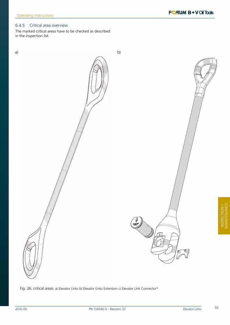
552016-05 PN 134046-D - Revision: 07 Elevator Links
Operating Instructions
INSP
EKTI
ON
UN
DW
ART
UN
GIN
SPEC
TIO
N /
MA
INTE
NA
NC
E
6.4.5 Critical area overviewThe marked critical areas have to be checked as described in the inspection list.
Fig. 26: critical areas: a) Elevator Links b) Elevator Links Extension c) Elevator Link Connector*
a) b)

56 Elevator Links PN 134046-D - Revision: 07 2016-05
Operating Instructions
INSPEC
TION
/ M
AIN
TENA
NC
E
c)

572016-05 PN 134046-D - Revision: 07 Elevator Links
Operating Instructions
INSP
EKTI
ON
UN
DW
ART
UN
GIN
SPEC
TIO
N /
MA
INTE
NA
NC
E
6.5 Cleaning
WARNING
Health hazards from service products!
Splashes of diluted drilling mud and small parts.
ALWAYS wear your personal protective equipment.
WEAR EYE PROTECTION!
WEAR PROTECTIVE GLOVES!
The operating conditions and operating environment result in contamination on the Links. Remove this contamination regularly to prevent incrustation and ensure safe operation of the machine.
To clean shut off the Links, disconnect from hydraulic system and lift out of rotary table. Remove upper ring and slip assembly.
6.5.1 Time of CleaningClean contamination from drilling from the Elevator Links regularly. The Elevator Links should be cleaned thoroughly at the end of each shift at the latest. Also observe the instructions in Chapter 6.2.
6.5.2 Procedure and Cleaning AgentsForum B + V Oil Tools recommends cleaning the Elevator Links with a high pressure steam cleaner.
Use it to clean the body and slip assembly thoroughly from inside and outside.
Clean particularly the shoulder inclines on the body, upper ring and slips.
Then lubricate the sliding surfaces as specified in Chapter 6.1.

58 Elevator Links PN 134046-D - Revision: 07 2016-05
Operating Instructions
INSPEC
TION
/ M
AIN
TENA
NC
E

592016-05 PN 134046-D - Revision: 07 Elevator Links
Operating Instructions
STO
RA
GE
/ DIS
POSA
L
STORAGE / DISPOSAL
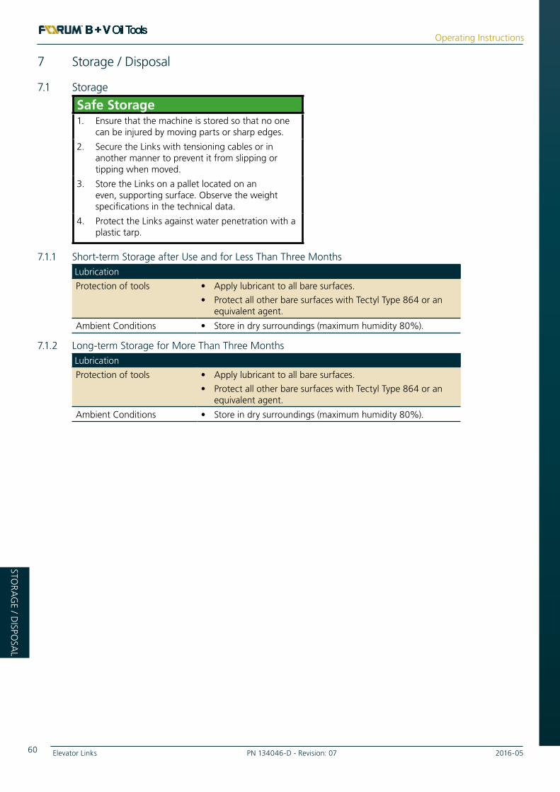
60 Elevator Links PN 134046-D - Revision: 07 2016-05
Operating Instructions
STOR
AG
E / DISPO
SAL
7 Storage / Disposal
7.1 Storage
Safe Storage1. Ensure that the machine is stored so that no one
can be injured by moving parts or sharp edges.
2. Secure the Links with tensioning cables or in another manner to prevent it from slipping or tipping when moved.
3. Store the Links on a pallet located on an even, supporting surface. Observe the weight specifications in the technical data.
4. Protect the Links against water penetration with a plastic tarp.
7.1.1 Short-term Storage after Use and for Less Than Three MonthsLubrication
Protection of tools • Apply lubricant to all bare surfaces.
• Protect all other bare surfaces with Tectyl Type 864 or an equivalent agent.
Ambient Conditions • Store in dry surroundings (maximum humidity 80%).
7.1.2 Long-term Storage for More Than Three MonthsLubrication
Protection of tools • Apply lubricant to all bare surfaces.
• Protect all other bare surfaces with Tectyl Type 864 or an equivalent agent.
Ambient Conditions • Store in dry surroundings (maximum humidity 80%).

612016-05 PN 134046-D - Revision: 07 Elevator Links
Operating Instructions
LAG
ERU
NG
/ EN
TSO
RGU
NG
STO
RA
GE
/ DIS
POSA
L
7.2 DisposalWhen used properly the machine does not pose any hazard for users or the environment.
Ensure that all service and operating products as well as replacement parts are disposed of safely and ecologically.
Please note specifically that Forum B + V Oil Tools is not obligated to take back used equipment.
7.3 List of Service Products UsedThe Safety Data Sheets on the service products used are included in the appendix to this operating manual.

62 Elevator Links PN 134046-D - Revision: 07 2016-05
Operating Instructions
STOR
AG
E / DISPO
SAL

632016-05 PN 134046-D - Revision: 07 Elevator Links
Operating Instructions
APP
END
IX
APPENDIX

64 Elevator Links PN 134046-D - Revision: 07 2016-05
Operating Instructions
APPEN
DIX
8 Appendix
A Sample of EC Certificate of Conformity
B Operating Instructions from Other Manufacturers

652016-05 PN 134046-D - Revision: 07 Elevator Links
Operating Instructions
AN
HA
NG
APP
END
IX
FORUM B + V Oil Tools GmbH
FORUM B + V Oil Tools GmbH Hermann-Blohm-Strasse 2, 20457 Hamburg P.O.Box 11 22 53, 20422 Hamburg, Germany Phone: +49 40 37022-6855, Fax: +49 40 37022-6899 E-Mail: [email protected] Internet: www.blohmvoss-oiltools.com Registered Office: Hamburg
Managing Directors: Jens Lutzhöft, James W. Harris Commercial Register: District Court of Hamburg, HRB 125 890 Tax-No.: 46/722/02375, VAT-ID. No.: DE 294 745 990 Banking: HSBC Trinkaus & Burkhardt AG BIC / SWIFT: TUBD DE DD XXX EUR-Acc.: IBAN: DE73 3003 0880 0012 8350 19 USD-Acc.: 401 / 2835 / 006 / IBAN: DE50 3003 0880 4012 8350 06 Stand: 20.11.2015
EC-DECLARATION OF CONFORMITY We, FORUM B + V Oil Tools GmbH Hermann-Blohm-Strasse 2 20457 Hamburg / Germany declare that the products: Elevator Link Extensions / Link Connectors which is the subject of this declaration, fulfils all of the relevant requirements of:
2006/42/EC Machinery Directive, 2014/34/EU ATEX Directive of Equipment for use in hazardous areas.
Amongst others following harmonized and technical standards and specifications were used: API 8C, 5. Edition Drilling and Production Hoisting Equipment (PSL1 and PSL2) DIN EN ISO 13535 Petroleum and natural gas industries - Drilling and
production equipment - Hoisting equipment DIN EN ISO 12100 Safety of machinery, Risk assessment and Risk Reduction DIN ISO 14121-1 Safety of machinery, Risk assessment DIN EN 13463-1 Non-electrical equipment for use in potentially explosive
atmospheres
Description of Product: The following named lifting accessory will be described in more detail in the accompanying Data Book and/or certificate and the associated Technical Documentation Product / Device Type:
Rated Capacity short tons per set Part Number: Serial Number: Delivery Date: B+V Order No.: Marking: II 2G T6 The Engineering Manager of FORUM B + V Oil Tools GmbH, Hermann-Blohm-Strasse 2, 20457 Hamburg, Germany, is authorized to compile the technical files. Documents in accordance to Directive 2014/34/EU Article 13 (1) b) ii) have been deposit at the notified body IBExU - Institut für Sicherheitstechnik GmbH, Fuchsmühlenweg 7, D-09599 Freiberg, Notified Body No. 0637, reference IB-14-6-001/200, Archive-No. 219/14. FORUM B + V Oil Tools has established a quality assurance system in accordance to ISO 9001 and API Q1 approved by API Quality Registrar, Washington D.C./USA, Registration No. 2850 + Q1-2769.
Hamburg, issued on _________________________ Authorized Representative: Name Jens Lutzhöft Position Managing Director
[see data book][see data book]
A. Sample of EC Declaration of Conformity
Fig. 27: EC Certificate of Conformity Sample Page I
Elevator Links
[see data book]
[see data book]
[see data book]
[see data book]
[see data book]
[see data book]

66 Elevator Links PN 134046-D - Revision: 07 2016-05
Operating Instructions
APPEN
DIX
FORUM B + V Oil Tools GmbH
FORUM B + V Oil Tools GmbH Hermann-Blohm-Strasse 2, 20457 Hamburg P.O.Box 11 22 53, 20422 Hamburg, Germany Phone: +49 40 37022-6855, Fax: +49 40 37022-6899 E-Mail: [email protected] Internet: www.blohmvoss-oiltools.com Registered Office: Hamburg
Managing Directors: Jens Lutzhöft, James W. Harris Commercial Register: District Court of Hamburg, HRB 125 890 Tax-No.: 46/722/02375, VAT-ID. No.: DE 294 745 990 Banking: HSBC Trinkaus & Burkhardt AG BIC / SWIFT: TUBD DE DD XXX EUR-Acc.: IBAN: DE73 3003 0880 0012 8350 19 USD-Acc.: 401 / 2835 / 006 / IBAN: DE50 3003 0880 4012 8350 06 Stand: 20.11.2015
EC-DECLARATION OF CONFORMITY We, FORUM B + V Oil Tools GmbH Hermann-Blohm-Strasse 2 20457 Hamburg / Germany declare that the products: Elevator Link Extensions / Link Connectors which is the subject of this declaration, fulfils all of the relevant requirements of:
2006/42/EC Machinery Directive, 2014/34/EU ATEX Directive of Equipment for use in hazardous areas.
Amongst others following harmonized and technical standards and specifications were used: API 8C, 5. Edition Drilling and Production Hoisting Equipment (PSL1 and PSL2) DIN EN ISO 13535 Petroleum and natural gas industries - Drilling and
production equipment - Hoisting equipment DIN EN ISO 12100 Safety of machinery, Risk assessment and Risk Reduction DIN ISO 14121-1 Safety of machinery, Risk assessment DIN EN 13463-1 Non-electrical equipment for use in potentially explosive
atmospheres
Description of Product: The following named lifting accessory will be described in more detail in the accompanying Data Book and/or certificate and the associated Technical Documentation Product / Device Type:
Rated Capacity short tons per set Part Number: Serial Number: Delivery Date: B+V Order No.: Marking: II 2G T6 The Engineering Manager of FORUM B + V Oil Tools GmbH, Hermann-Blohm-Strasse 2, 20457 Hamburg, Germany, is authorized to compile the technical files. Documents in accordance to Directive 2014/34/EU Article 13 (1) b) ii) have been deposit at the notified body IBExU - Institut für Sicherheitstechnik GmbH, Fuchsmühlenweg 7, D-09599 Freiberg, Notified Body No. 0637, reference IB-14-6-001/200, Archive-No. 219/14. FORUM B + V Oil Tools has established a quality assurance system in accordance to ISO 9001 and API Q1 approved by API Quality Registrar, Washington D.C./USA, Registration No. 2850 + Q1-2769.
Hamburg, issued on _________________________ Authorized Representative: Name Jens Lutzhöft Position Managing Director
[see data book] [see data book]
Fig. 28: EC Certificate of Conformity Sample Page I
[see data book]
[see data book]
[see data book]
[see data book]
[see data book]
[see data book]

672016-05 PN 134046-D - Revision: 07 Elevator Links
Operating Instructions
AN
HA
NG
APP
END
IX
B. Third Party Documents
I Nord Lock Washer (excerpt from Third Party Product information)
Nord-Lock washersProduct information
ENG
LISH
• M
ETR
IC
Excerpt for B+V Operation Manual - Annex

68 Elevator Links PN 134046-D - Revision: 07 2016-05
Operating Instructions
APPEN
DIX
Øo
Øi
T
NL3 M3 #5 3,4 7,0 1,8 200 0,03
NL3,5 M3,5 #6 3,9 7,6 1,8 200 0,04
NL3,5sp M3,5 #6 3,9 9,0 1,8 200 0,06
NL4 M4 #8 4,4 7,6 1,8 200 0,04
NL4sp M4 #8 4,4 9,0 1,8 200 0,06
NL5 M5 #10 5,4 9,0 1,8 200 0,05
NL5sp M5 #10 5,4 10,8 1,8 200 0,11
NL6 M6 6,5 10,8 1,8 200 0,07
NL6sp M6 6,5 13,5 2,5 200 0,20
NL1/4” 1/4” 7,2 11,5 1,8 200 0,08
NL1/4”sp 1/4” 7,2 13,5 2,5 200 0,18
NL8 M8 5/16” 8,7 13,5 2,5 200 0,15
NL8sp M8 5/16” 8,7 16,6 2,5 200 0,28
NL3/8” 3/8” 10,3 16,6 2,5 200 0,23
NL3/8”sp 3/8” 10,3 21,0 2,5 200 0,48
NL10 M10 10,7 16,6 2,5 200 0,22
NL10sp M10 10,7 21,0 2,5 200 0,47
NL11 M11 7/16” 11,4 18,5 2,5 200 0,29
NL12 M12 13,0 19,5 2,5 200 0,29
NL12sp M12 13,0 25,4 3,4 100 0,93
NL1/2” 1/2” 13,5 19,5 2,5 200 0,27
NL1/2”sp 1/2” 13,5 25,4 3,4 100 0,90
NL14 M14 9/16” 15,2 23,0 3,4 100 0,56
NL14sp M14 9/16” 15,2 30,7 3,4 100 1,41
NL16 M16 5/8” 17,0 25,4 3,4 100 0,67
NL16sp M16 5/8” 17,0 30,7 3,4 100 1,28
NL18 M18 19,5 29,0 3,4 100 0,85
NL18sp M18 19,5 34,5 3,4 100 1,58
NL3/4” 3/4” 20,0 30,7 3,4 100 1,05
NL3/4”sp 3/4” 20,0 39,0 3,4 100 2,20
NL20 M20 21,4 30,7 3,4 100 0,93
NL20sp M20 21,4 39,0 3,4 100 2,03
NL22 M22 7/8” 23,4 34,5 3,4 100 1,29
NL22sp M22 7/8” 23,4 42,0 4,6 50 3,31
NL24 M24 25,3 39,0 3,4 100 1,68
NL24sp M24 25,3 48,5 4,6 50 4,51
NL1” 1” 27,9 39,0 3,4 100 1,53
NL1”sp 1” 27,9 48,5 4,6 50 4,20
NL27 M27 28,4 42,0 5,8 50 3,29
NL27sp M27 28,4 48,5 5,8 25 5,39
NL30 M30 1 1/8” 31,4 47,0 5,8 50 4,20
NL30sp M30 1 1/8” 31,4 58,5 6,6 25 8,96
NL33 M33 1 1/4” 34,4 48,5 5,8 25 3,97
NL33sp M33 1 1/4” 34,4 58,5 6,6 25 8,31
NL36 M36 1 3/8” 37,4 55,0 5,8 25 5,59
NL36sp M36 1 3/8” 37,4 63,0 6,6 25 9,15
NL39 M39 1 1/2” 40,4 58,5 5,8 25 6,28
NL42 M42 43,2 63,0 5,8 25 7,47
NL45 M45 1 3/4” 46,2 70,0 7,0 25 10,20
NL48 M48 49,6 75,0 7,0 25 12,00
NL52 M52 2” 53,6 80,0 7,0 25 13,00
NL56 M56 2 1/4” 59,1 85,0 7,0 10 13,50
NL60 M60 63,1 90,0 7,0 10 15,20
NL64 M64 2 1/2” 67,1 95,0 7,0 10 16,70
NL68 M68 71,1 100,0 9,5 1 28,19
NL72 M72 75,1 105,0 9,5 1 30,70
NL76 M76 3” 79,1 110,0 9,5 1 33,31
NL80 M80 3 1/8” 83,1 115,0 9,5 1 36,02
NL85 M85 88,1 120,0 9,5 1 37,84
NL90 M90 92,4 130,0 9,5 1 47,67
NL95 M95 97,4 135,0 9,5 1 49,81
NL100 M100 4” 103,4 145,0 9,5 1 58,91
NL105 M105 108,4 150,0 9,5 1 61,28
NL110 M110 113,4 155,0 9,5 1 63,65
NL115 M115 118,4 165,0 9,5 1 75,28
NL120 M120 123,4 170,0 9,5 1 77,94
NL125 M125 128,4 173,0 9,5 1 76,63
NL130 M130 5” 133,4 178,0 9,5 1 79,17
NL3 – NL8 Ø
i ±0,1 mm
NL10 – NL42 Ø
i ±0,2 mm
NL45 – NL130 Ø
i +0,5 / -0,0 mm
NL3 – NL24 Ø
o ± 0,2 mm
NL27 – NL42 Ø
o ± 0,3 mm
NL45 – NL130 Ø
o +0,0 / -2,0 mm
NL3 – NL42 T ± 0,25 mm NL45 – NL130 T ± 0,75 mm
8
Nord-Lock steel washers EN 1.7182 or equivalent, zinc flake coating (Delta Protekt®), through hardened
Washer size Bolt size øi
[mm]ø
o
[mm]Thickness T
[mm]Min. package
[pairs]Approx. weightkg / 100 pairs
Metric UNC
• Please consult our website for current dimensions and 2D / 3D CAD models: www.nord-lock.com/cad
Nord-Lock washers made of steel with zinc flake coating are standard stock items, yet subject to prior sale.
Note that washers with thickness 6,6 mm has a thickness tolerance +0,0 / -0,5 mm
Dimension chart

692016-05 PN 134046-D - Revision: 07 Elevator Links
Operating Instructions
AN
HA
NG
APP
END
IX
a. Torque Guidelines
NL3 M3 0,5 1,3 2,4 2,1 2,4 1,3 2,0
NL4 M4 0,7 3,1 4,2 4,4 4,2 3,1 3,5
NL5 M5 0,8 6,0 6,8 8,0 6,8 6,0 5,6
NL6 M6 1,0 10,5 9,7 13,2 9,7 10,5 8,0
NL8 M8 1,25 25 18 30 18 25 15
NL10 M10 1,5 49 28 49 28 50 23
NL12 M12 1,75 85 40 83 40 85 33
NL14 M14 2,0 135 55 131 55 136 46
NL16 M16 2,0 205 75 197 75 208 62
NL18 M18 2,5 288 92 275 92 291 76
NL20 M20 2,5 402 118 382 118 408 97
NL22 M22 2,5 548 146 517 146 557 120
NL24 M24 3,0 693 169 652 169 703 140
NL27 M27 3,0 1 010 221 945 221 1028 182
NL30 M30 3,5 1379 269 1 286 269 1 401 222
NL33 M33 3,5 1855 333 1 722 333 1 889 275
NL36 M36 4,0 2 394 392 2219 392 2 436 324
NL39 M39 4,0 3 087 468 2852 468 3145 387
NL42 M42 4,5 3 820 538 3 525 538 3 890 445
NL3 M3 0,5 2,0 3,9 3,8 4,1
NL4 M4 0,7 4,6 6,7 7,6 7,1
NL5 M5 0,8 9,1 10,9 13,6 11,5
NL6 M6 1,0 15,8 15,4 21,8 16,3
NL8 M8 1,25 38 28 47 30
NL10 M10 1,5 75 44 93 47
NL12 M12 1,75 128 65 151 68
NL14 M14 2,0 204 89 232 94
NL16 M16 2,0 311 120 342 127
NL18 M18 2,5 437 148 467 156
NL20 M20 2,5 610 188 638 198
NL22 M22 2,5 831 233 852 246
NL24 M24 3,0 1 052 270 1064 286
NL27 M27 3,0 1533 352 1519 372
NL30 M30 3,5 2091 430 2042 454
NL33 M33 3,5 2 815 532 2710 562
NL36 M36 4,0 3633 626 3463 662
NL39 M39 4,0 4683 748 4415 790
NL42 M42 4,5 5799 860 5429 908
NL3 M3 0,5 1,8 3,2 3,5 3,4
NL4 M4 0,7 4,1 5,6 7,0 5,9
NL5 M5 0,8 8,1 9,1 12,5 9,6
NL6 M6 1,0 14,1 12,9 20,1 13,6
NL8 M8 1,25 34 23 44 25
NL10 M10 1,5 67 37 73 39
NL12 M12 1,75 115 54 121 57
NL14 M14 2,0 183 74 188 78
NL16 M16 2,0 279 100 281 106
NL18 M18 2,5 391 123 388 130
NL20 M20 2,5 547 156 534 165
NL22 M22 2,5 745 194 719 205
NL24 M24 3,0 942 225 902 238
NL27 M27 3,0 1375 294 1297 310
NL30 M30 3,5 1875 358 1755 378
NL33 M33 3,5 2526 443 2340 468
NL36 M36 4,0 3259 522 3003 551
NL39 M39 4,0 4203 624 3845 659
NL42 M42 4,5 5202 716 4740 757
9
Torque guidelines Nord-Lock steel washers with zinc flake coating (Delta Protekt®)
Nord-Lock steel washers with electro zinc plated bolt grade 8.8
Cu/C paste = Copper/graphite paste (Molykote® 1000)G
F = ratio of yield point
µth = thread friction
µb = washer friction
1 N = 0,225 lb1 Nm = 0,738 ft-lb
Nord-Lock steel washers with non-plated bolt grade 12.9Nord-Lock steel washers with non-plated bolt grade 10.9
Torque guidelines for other bolt grades are available through your local Nord-Lock representative.
Oil, GF=75%
µth= 0,10, µ
b = 0,16
Cu/C paste, GF=75%
µth = 0,11, µ
b = 0,16
Dry, GF=62%
µth = 0,15, µ
b= 0,18
Washer size
Bolt size
Pitch [mm]
Torque [Nm]
Clamp load [kN]
Torque [Nm]
Clamp load [kN]
Torque [Nm]
Clamp load [kN]
Washer size
Bolt size
Pitch [mm]
Oil, GF=71%
µth = 0,13, µ
b = 0,14
Cu/C paste, GF=75%
µth = 0,11, µ
b = 0,15
Torque [Nm]
Clamp load [kN]
Torque [Nm]
Clamp load [kN]
Washer size
Bolt size
Pitch [mm]
Oil, GF=71%
µth = 0,13, µ
b= 0,12
Cu/C paste, GF=75%
µth = 0,11, µ
b = 0,15
Torque [Nm]
Clamp load [kN]
Torque [Nm]
Clamp load [kN]

70 Elevator Links PN 134046-D - Revision: 07 2016-05
Operating Instructions
APPEN
DIX
12
Nord-Lock washers joint guide
Tapped holesNord-Lock washers safely lock the bolt against the underlying surface.
Stud boltsNord-Lock washers safely lock the nut on stud bolts and eliminate the need for adhesives.
Through holesAs for all locking washers, through holes require two pairs of Nord-Lock washers – one pair
for securing the bolt and a second pair for securing the nut.
Turn both fasteners in order to close the cams on both washer pairs before tightening to
minimize settlements. Keep the nut secure whilst tightening the bolt.
Counter boresThe outer diameter of regular Nord-Lock washers is designed for counter-bore
holes according to DIN 974, i.e. the washers fit under the head of standard bolts.
Applications with large / slotted holes or soft underlying surfacesTo optimize the load distribution for applications with large / slotted holes
or with soft underlying surface, use a flanged nut / bolt together with
Nord-Lock “sp” washers with enlarged outer diameter.
Soft underlying surfacesLarge / slotted holes
If your application corresponds to one or more of the mentioned design criteria, contact your
Nord-Lock representative and we will help you find an alternative solution.
Designs where Nord-Lock washers are not recommended• Mating surfaces that are not locked in place (see left figure)
• Mating surfaces harder than the washers
• Very soft mating surface, e.g. wood, plastic
• Applications with extremely large settlements
• Non-preloaded joints

712016-05 PN 134046-D - Revision: 07 Elevator Links
Operating Instructions
AN
HA
NG
APP
END
IX
6
Nord-Lock washers are easy and effective to use while
ensuring structural security for applications exposed to
vibration and dynamic loads.
Installing the washersThe pre-assembled washers are installed in pairs, cam face to
cam face. Nord-Lock recommends lubrication when possible.
TighteningTighten Nord-Lock washers with standard tools according
to the guidelines (on page 9-11). Tightening guidelines for
other bolt grades are available through your Nord-Lock
representative.
UntighteningUntightening Nord-Lock washers is as simple as tightening.
Note that since the locking function is not based on increased
friction, the untightening torque is generally lower than the
tightening torque. Therefore it is not possible to measure off-
torque as verification of locking function.
Reusing Nord-LockNord-Lock washers can normally be reused. As with
all fasteners, they should be inspected for wear before
reassembly. Make sure that the washers are reinstalled
correctly cam face to cam face. Nord-Lock recommends
lubrication of fasteners before reuse in order to minimize
changes in friction conditions.
Using Nord-Lock washers
When the two criteria above are met, you have verified
the locking function of the Nord-Lock washers.
Utilize the advantages of lubrication Nord-Lock recommends the use of a high quality, anti-seize
lubricant as it improves the tightening results. It is especially
beneficial for large sized bolts and stainless steel applications.
The Nord-Lock wedge-locking function provides safe locking
in both dry and lubricated conditions. Benefits of lubricated
fasteners include:
• Improve reusability
• Reduce friction and deviation
• Facilitate assembly and disassembly
• Reduce torsion stress due to minimized thread friction
• Avoid galling and thread seizure
• Additional protection against corrosion
When untightening a bolt secured by Nord-Lock washers, check that sliding occurs between the cam faces.
After disassembly, impression marks must be visible on both the fastener and the contact surface.
Possible to verify the locking function

72 Elevator Links PN 134046-D - Revision: 07 2016-05
Operating Instructions
APPEN
DIX
SAFETY DATA SHEET according to Regulation (EC) No. 1907/2006. Product name: AVIATICON FETT XRF Date: 28/05/2009 Revised: 28/05/2009 Page 1/4
1. IDENTIFICATION OF THE SUBSTANCE/PREPARATION AND OF THE COMPANY/UNDERTAKING 1.1 Identification of substance or preparation 1.1.1 Trade name: AVIATICON FETT XRF 1.1.2 Use of the substance/the preparation: Grease.
1.2 Company/undertaking identification Supplier (manufacturer/importer/downstream user/distributor): FINKE MINERALÖLWERK GMBH, Rudolf-Diesel-Straße 1, D-27374 Visselhövede Telephone: (Germany ++49) - 04262 798 Fax: (Germany ++49) - 04262 799519 Department responsible for information: Technical service. E-mail (competent person): [email protected] Emergency telephone: (Germany ++49) - 04262 79-9601 (This number is serviced during office hours only.)
2. HAZARDS IDENTIFICATION 2.1 Classification: Not classified as dangerous under EC criteria. R-Phrases: none 2.2 Information pertaining to special dangers for human and environment: The product does not have to be
labelled due to the calculation procedure of the “General Classification guideline for preparations of the EU” in the latest valid version.
This product is not considered to be especially hazardous to health, but should be handled in accordance with good industrial hygiene and safety practices.
Environmental hazards: Not classified as dangerous under EC criteria. Classification system: The classification was made according to the latest editions of the EC-lists, and
expanded upon from company and literature date. 3. COMPOSITION/INFORMATION ON INGREDIENTS 3.1 Chemical characterization Substance: [ ] Preparation: [ X ] 3.1.1 Chemical characterization (preparation): Lubricating grease. Composition of sodium soap and mineral oil. 3.1.2 Hazard ingredients: Chemical name EC-No. CAS-No. Content, unit Hazard symbol(s) R-Phrases Zinc dialkydithiophosphate 68649-42-3 < 2,5 wt.-% Xi, N 36-51/53 3.1.3 Additional information: No component is present at sufficient concentration to require a hazardous
classification for health in accordance with EC legislation. Full text of R-Phrases: see section 16. 4. FIRST AID MEASURES 4.1 General information: No special measures required. Remove and clean stained or soaked
clothing immediately. Consult a physician if problems persist. 4.2 In case of inhalation: No special precautions necessary. Move to fresh air in case of accidental
inhalation of dust or fumes from overheating or combustion. 4.3 In case of skin contact: Wash skin thoroughly with plenty of soap and water. 4.4 In case of eye contact: In case of contact with eyes, rinse immediately thoroughly with plenty of
running water. Consult an ophthalmologist if any pain or redness develops or persists.
4.5 In case of ingestion: Seek medical advice. If contamination of the mouth occurs, wash out thoroughly with water. Do not induce vomiting. Never give anything by mouth to an unconscious person.
4.6 Self-protection of the first aider: First aider: Pay attention to self-protection. 4.7 Information to physician: Treatment should in general be symptomatic. If aspiration should occur,
transport casualty immediately to hospital.
5. FIRE FIGHTING MEASURES 5.1 Suitable extinguishing media: Use foam, dry chemical powder, sand or carbon dioxide (CO2). 5.2 Extinguishing media which must not be used for safety reasons: Do not use water. 5.3 Special exposure hazards arising from the substance or preparation itself, combustion products, resulting
gases: Carbon monoxide, carbon dioxide, sulphur dioxide and other toxic fumes may be evolved on burning or exposure to strong heat.
5.4 Special protective equipment for fire-fighters: Full protective clothing and self-contained breathing apparatus. 5.5 Additional information: Water may be used to cool nearby heat exposed areas/objects/packages.
6. ACCIDENTAL RELEASE MEASURES 6.1 Personal precautions: Use personal protective equipment. Avoid contact with skin and eyes. Particular danger
of slipping on leaked/spilled product. 6.2 Environmental precautions: Prevent contamination of soil and water. 6.3 Methods for cleaning up: Prevent from spreading by making a barrier with sand, earth or other containment
material. Remove with shovel. Absorb remains with sand or other suitable inert absorbent material. 6.4 Additional information: In case of large spills contact the appropriate authorities.
II Data-sheet Grease

732016-05 PN 134046-D - Revision: 07 Elevator Links
Operating Instructions
AN
HA
NG
APP
END
IX
SAFETY DATA SHEET according to Regulation (EC) No. 1907/2006. Product name: AVIATICON FETT XRF Date: 28/05/2009 Revised: 28/05/2009 Page 2/4
7. HANDLING AND STORAGE 7.1 Handling 7.1.1 Advices on safe handling: If properly used no special handling precautions required. When handling heavy
containers, wear safety shoes and use suitable tools. Avoid contact with eyes. Avoid contact with fresh or used product. Good working practices, high standard of personal hygiene and plant cleanliness must be maintained at all times. Wash hands thoroughly after contact.
7.1.2 Precautions against fire and explosion: No special measures required. 7.1.3 Further information: none
7.2 Storage 7.2.1 Requirements for storage rooms and vessels: Observe all storage regulations. Keep in original containers only. Keep containers dry. 7.2.2 Hints on storage assembly: Do not store together with oxidizing agents. Do not store in the same place with
foodstuffs. 7.2.3 Further information on storage conditions: Protect against pollution. Protect from frost and direct sunlight.
Storage temperatures: ambient (5-30 °C).
8. EXPOSURE CONTROLS/PERSONAL PROTECTION 8.1 Exposure limit values: Ensure good ventilation. Avoid, as far as reasonably practicable, inhalation of vapour,
mists or fumes generated during use. If vapour, mists or fumes are generated, their concentration in the workplace air should be controlled to the lowest reasonably practicable level. Comply with current local occupational exposure limit. Where not established, it is recommended that mineral oil mists are kept below 5 mg/m³ (8 hr TWA).
8.1.1 CAS No Component name Code Value Unit Remark oil mist 8 hours 5 mg/m³ TWA, 5 h 8.1.2 Additional Information: The lists valid during the making were used as basis.
8.2 Personal protection equipment 8.2.1 Respiratory protection: Not required in normal case. 8.2.2 Hand protection: Protective gloves. Material of gloves: Nitrile rubber, NBR. Penetration time of glove material: Nitrile: thickness 0,4 mm, breakthrough time > 240 min. The exact breakthrough time has to be found out by the manufacturer of the
protective gloves and has to be observed. 8.2.3 Eye protection: Not normally required. If contact may reasonably be anticipated, a full face visor or
chemical goggles as appropriate should be worn. 8.2.4 Body protection: Protective work clothes. 8.2.5 General protective and hygiene measures: The usual precautionary measures are to be adhered to when
handling chemicals. Do not eat and drink while working. Keep away from food and drink. Change heavily contaminated clothing as soon as reasonable practicable. Wash any contaminated underlying skin with soap and water. Avoid contact with eyes. Avoid close or long term contact with the skin. Wash hands thoroughly after contact. After washing the application of a suitable conditioning cream may help to prevent cracking, fissuring or dryness of the skin. Don’t keep oily rags in your pockets.
9. PHYSICAL AND CHEMICAL PROPERTIES 9.1 Appearance 9.1.1 Physical state: pasty 9.1.2 Colour: yellowish-brown 9.1.3 Odour: characteristic
9.2 Important health, safety and environmental information Safety relevant basic data 9.2.1 pH value: g/l water at °C Not applicable. 9.2.2 Boiling point/range: Not determined. 9.2.3 Melting point/range: dropping point 150 °C DIN/ISO 2176 9.2.4 Flash point: (base oil) > 200 °C DIN/ISO 2592 9.2.5 Inflammability (solid/gaseous): No data available. 9.2.6 Inflammation point: No data available. 9.2.7 Autoignition (solid/gaseous): Product is not selfigniting. 9.2.8 Fire hazard properties: No data available. 9.2.9 Danger of explosion: Product does not present an explosion hazard. 9.2.10 Explosion limits: lower % upper % No data available. 9.2.11 Vapour pressure: at 20 °C < 0,1 hPa 9.2.12 Density: at 20 °C < 1,000 g/cm³ 9.2.13 Solubility in water: at 20 °C dispersible 9.2.14 n-Octanol/water partition coefficient: No data available. 9.2.15 Viscosity, kinematic: at 40 °C (base oil) Approximately 190 mm²/s DIN 51562/T1 9.2.16 Solvent content: %
9.3 Other information: The data are subject to usual tolerances.

74 Elevator Links PN 134046-D - Revision: 07 2016-05
Operating Instructions
APPEN
DIX
SAFETY DATA SHEET according to Regulation (EC) No. 1907/2006. Product name: AVIATICON FETT XRF Date: 28/05/2009 Revised: 28/05/2009 Page 3/4
10. STABILITY AND REACTIVITY 10.1 Conditions to avoid: Products of this type are stable and unlikely to react in a hazardous manner under
normal conditions of use. This material is combustible. 10.2 Materials to avoid: Avoid contact with strong oxidizing agents. 10.3 Hazardous decomposition products: Thermal decomposition can produce a variety of compounds, the precise
nature of which will depend on the decomposition conditions. Incomplete combustion/thermal decomposition will generate smoke, carbon dioxide, carbon monoxide and sulphur dioxide.
10.4 Further remarks: none
11. TOXICOLOGICAL INFORMATION 11.1 Acute effects (toxicity tests) 11.1.1 Acute toxicity:
Acute toxicity: Effective dose: Species: Method: Remark:
Oral LD50 Rat No data available for the product.
Dermal LD50 Rabbit No data available for the product.
Inhalative LC50 Rat No data available for the product.
11.1.2 Specific symptoms in animal studies: No data available for this formulation. 11.1.3 Irritant and corrosive effects: Irritant effect on the skin: Unlikely to cause harm to the skin on brief or occasional contact. Irritant effect on the eyes: No irritant effects.
Irritant effect on the respiratory tract: Normally low inhalation risk due to low volatility. High temperatures or mechanical processing may form oil mist, vapours or smoke which may irritate the respiratory system.
11.1.4 Sensitization: In case of skin contact: No sensitizing effects known. In case of inhalation: No sensitizing effects known. Remark: none 11.1.5 Repeated dose toxicity (sub-acute to chronic toxicity): Repeated or prolonged exposure may cause irritation to
eyes and skin. 11.1.6 CMR effects (carcinogenity, mutagenicity and toxicity for reproduction): No particulars available.
11.2 Experiences made in practice 11.2.1 Observations relevant to classification: - 11.2.2 Other observations: -
11.3 General remarks: When used and handled according to specifications, this product doesn’t have any particular harmful effects according to our experience and the information provided to us.
12. ECOLOGICAL INFORMATION 12.1 Ecotoxicity 12.1.1 Aquatic toxicity: No data available.
12.2 Mobility 12.2.1 Known or predicted distribution to environmental compartments: No data available. 12.2.2 Adsorption/Desorption: No data available.
12.3 Persistence and degradability: Not expected to be readily biodegradable. 12.3.1 Bioaccumulative potential: No data available.
12.4 Other adverse effects: This product is a mixture of non-volatile components, which are not expected to be released to air in any significant quantities.
12.5 Further ecological information: Do not allow product to reach ground water, water course or sewage system. Danger to drinking water if even small quantities leak into the ground.
13. DISPOSAL CONSIDERATIONS 13.1 Product 13.1.1 Recommendation: Disposal in accordance with local and national regulations. Dispose to licensed disposal
contractor. Must not be disposed of together with household garbage. Do not allow product to reach sewage system.
13.1.2 Waste codes / waste designations according to EWC / AVV: EWC-Code 1201 12 (used Wax and Greases). The waste disposal code is just a recommendation. Contact your local experts to obtain information about use
or disposal of the material involved. The indication about disposal refers to the product and its residues. If the product is mixed with other
materials or preparations an individual evaluation should be necessary. Classification of waste is always the responsibility of the end user.

752016-05 PN 134046-D - Revision: 07 Elevator Links
Operating Instructions
AN
HA
NG
APP
END
IX
SAFETY DATA SHEET according to Regulation (EC) No. 1907/2006. Product name: AVIATICON FETT XRF Date: 28/05/2009 Revised: 28/05/2009 Page 4/4
13.2 Appropriate packaging 13.2.1 Recommendation: Contaminated packages should be optimally emptied and can be reused when adequately
cleaned. Disposal must be made according to official regulations. 13.2.2 Recommendet detergent: No data available.
13.3 Additional information: none
14. TRANSPORT INFORMATION 14.1 Land transport (ADR/RID): Not classified as hazardous for transport. 14.2 Sea transport (IMDG-Code/GGVSee): Not classified as hazardous for transport. 14.3 Air transport (ICAO/IATA-DGR): Not classified as hazardous for transport.
15. REGULATORY INFORMATION 15.1 EU regulations 15.1.1 Chemical Safety Assessment: For this preparation a chemical safety assessment has not been carried out. 15.1.2 Labelling
Hazard symbols and hazard statements: No special labelling required. This product is not subject to identification regulations under EC Directives and the Ordinance on Hazardous
Materials (GefStoffV). Observe the general safety regulations when handling chemicals. Hazard components for labelling: none
R-Phrases: none S-Phrases: none Special provisions concerning the labelling of certain preparations: Safety data sheet available for
professional user on request. 15.1.3 Other EU regulations: 15.2 National regulations (Germany) 15.2.1 Restrictions of occupation: 15.2.2 Chemikalienverbotsverordnung: Not applicable. 15.2.3 Störfallverordnung (12. BImSchV): 15.2.4 Betriebssicherheitsverordnung (BetrSichV): Not classified. 15.2.5 Technische Anleitung Luft (TA-Luft): 15.2.6 Wassergefährdungsklasse (water hazard class): WGK 1 [classification, according to VwVwS
(27.07.05)/Administrative regulations on the classification of water contaminants], slightly hazardous for water. 15.2.7 Other regulations, restrictions and prohibition regulations: Pay attention to VAwS (regulations for plants
handling water hazardous substances) of the different federal states in Germany.
16. OTHER INFORMATION 16.1 Full text of risk phrases referred to in section 2 and 3: R 36 Irritating to eyes. R 51/53 Toxic to aquatic organisms, may cause long-term adverse effects in the aquatic environment. 16.2 Further information: This information is based on our current knowledge and is intended to describe the
product for the purpose of health, safety and environmental requirements only. It should not therefore be construed as guaranteeing any specific property of the product.
16.3 Issued by: Technical service. Telephone: (Germany ++49) - 04262 79-9601.

76 Elevator Links PN 134046-D - Revision: 07 2016-05
Operating Instructions
APPEN
DIX
STARPOINT - VRS
Please visit our website at www.rud.com.au to register for your FREE CD with CAD Files
Complies with the machinery directives 2006/42/EC
User Instructions - Part 1 Safety instructionsThis safety instruction / declaration of the manufacturer has to be kept on file for the whole lifetime of the product.
EC-Declaration of the manufacturerAccording to the Machinery Directive 2006/42/EC, annex II B and amendments.
We hereby declare that the design and construction of the equipment detailed within this document, adheres to the appropriate level of health and safety of the corresponding EC regulation.Any un-authorised modification of the equipment and/or any incorrect usage of the equipment not adhered to within these user instructions waivers this declaration invalid. The equipment must be regularly tested and inspected as per BGR 500. Failure to carry out the recommended maintenance and testing of the equipment waivers this declaration invalid.
Designation of the equipment: LIFTINg POINTType: Load ring - STARTPOINT VRSManufacturer’s sign:Drawings are available on request as hard copies or DXF files. Drawings can also be downloaded from our website: www.rud.com.au.Check the RUD website: www.rud.com.au for product information.Workshop wall charts available upon request for working load limits (WLL).
MO045199
III Data-sheet RUD VRSF

772016-05 PN 134046-D - Revision: 07 Elevator Links
Operating Instructions
AN
HA
NG
APP
END
IX
STARPOINT - VRS
User Instructions - Part 2 1. Reference should be made to relevant standards and other statutory regulations. Inspections should be carried out by competent persons only.2. Before installing and every use, visually inspect RUD lifting points, with particular attention to any evidence of corrosion, wear and weld cracks and deformations. Please ensure compatibility of bolt thread and tapped hole.3. The material construction to which the lifting point will be attached, should be of adequate strength to withstand forces during lifting without deformation. RUD, with reference to the German testing authority BG, recommends the following minimum for bolt lengths:
1.5 x M in steel (minimum quality S235JR [1.0037]) • ≈ AS3678 GR250.1.5 x M in cast iron (for example GG 25)• 2 x M in aluminium alloys• 2.5 x M in aluminium-magnesium alloys• ( M = diameter of RUD lifting point bolt, e.g. M 20 )•
When lifting light metals, nonferrous heavy metals and gray cast iron, the thread has to be chosen in such a way that the working load limit of the thread corresponds to the requirements of the respective base material.4. The lifting points must be positioned on the load in such a way that movement is avoided during lifting.a) For single leg lifts, the lifting point should be vertically above the centre of gravity of the load.b) For two leg lifts, the lifting points must be equidistant to/or above the centre of gravity of the load.c) For three and four leg lifts, the lifting points should be arranged symmetrically around the centre of gravity in the same plane if possible.5. Load Symmetry: The working load limit of individual RUD lifting points are calculated using the following formula and are based on symmetrical loading:
NOTE: For WLL Calculations• ß angle is taken from the vertical plane.• Included angle is the angle between the sling legs.6. Safety: When lifting points are used in a multileg assembly, care should be taken to calculate the WLL (Working Load Limit) due to the deration caused by forces acting in multiple directions. The reduction in WLL (Working Load Limit) for multileg assemblies should be checked with relevant Standards e.g. AS 3775-2004 - Chain Slings-Gr t (8)The lifting points should be mounted in such a way that they may easily be accessed for inspection and assembly/disassembly of the sling.7. A plane bolting surface must be guaranteed to ensure correct mating of the lift component.8. For fitting without tools and for inspection of the compatibility of bolt thread and tapped hole the STARPOINT can be delivered with a tempered key (type: VRS-F). Simply engage the Hexagon socket bolt with the star profile key and tighten by hand. Disengage the key before attaching the lifting mean.
For a long term application the VRS should be tightened to torque according to relevant table (+/- 10%).9. To prevent unintended dismounting through shock loading, rotation or vibration, thread locking fluid such as Loctite (depending on the application, please refer to the manufacturer’s instruction) should be used to secure the eyebolt.10. The STARPOINT has to be adjustable through 360° when fitted and with key disengaged. Adjust to direction of pull before attaching of the lifting means.Attention: STARPOINT’s are not suitable for rotation under load!11. All fittings connected to the eyebolt should be free moving.When connecting and disconnecting the lifting means (wire ropes, chain slings, round slings) pinches and impacts should be avoided. Damage to lifting components caused by sharp corners should also be avoided.12. Effects of temperature:Due to the DIN/EN bolts that are used with the STARPOINT the working load limit should be reduced accordingly:-10° to 100°C no reduction 14°F to 212°F100° to 200°C minus 15% 212°F to 392°F200° to 250°C minus 20% 392°F to 482°F250° to 350°C minus 25% 482°F to 662°FTemperatures above 350°C (662°F) are not permitted.13. RUD lifting points must not be used under chemical influences such as acids, alkaline solutions and vapours e.g. in pickling baths or hot dip galvanising plants. If this cannot avoided, please contact the manufacturer indicating the concentration, period of penetration and temperature of use.14. The position where the lifting points should be attached should be clearly marked with colour. 15. After fitting, an annual inspection or sooner if conditions dictate should be under taken by a competent person examining the continued suitability. Also inspect after damage and special occurrences.
Inspection criteria concerning paragraphs 2 and 15:Ensure compatibility of bolt thread and tapped hole.• The lifting point should be complete.• The working load limit and manufacturers stamp should be • clearly visible.Deformation of the component parts such as body and • bolt.Mechanical damage, such as notches, particularly in high • stress areas.Wear should be no more than 10% of cross sectional • diameter.Evidence of corrosion.• Evidence of cracks.• Damage to the bolt and/or thread.• The body of the STARPOINT must be free to rotate.•
Any non-adherence to this advice may result damages of persons and / or materials!
WLL = required of lifting point/individual leg (kg)G = load weight (kg)n = number of load bearing legsß = angle of inclination of the individual leg
WLL = G n x cos ß
78 Elevator Links PN 134046-D - Revision: 07 2016-05
Operating Instructions
APPEN
DIX
STARPOINT - VRS
User Instructions - Part 3
LIT00017/L&L/Jan10
Type WLL (t)
Weight (kg) A B C D E g K L M N S Ref.-No.
VRSRef.-No. VRS-F
VRS-M8 0.4 0.1 34 11 8.5 25 25 28 47 12 8 6 16 7100554 8500911
VRS-M10 0.4 0.1 34 11 8.5 25 25 28 47 15 10 6 15 7982219* 7104029
VRS-M12 0.75 0.2 42 13 10 30 30 34 56 18 12 8 18 7982220* 7101313
VRS-M16 1.5 0.3 49 15 14 35 35 40 65 24 16 10 22 7982221** 7101314
VRS-M20 2.3 0.5 57 17 16 40 40 50 75 30 20 12 27.5 7982222** 7101315
VRS-M24 3.2 0.9 69 21 19 48 48 60 90 36 24 14 33 7982223** 7101316
VRS-M30 4.5 1.7 86 26 24 60 60 75 112 45 30 17 41.5 7982224*** 7101317
VRS-M36 7 2.9 103 32 29 72 75 90 135 54 36 22 49.5 7984198 7984201
VRS-M42 9 4.6 120 38 34 82 85 105 158 63 42 24 58 7984199 7984202
VRS-M48 12 7.0 137 43 38 94 100 120 180 72 48 27 66 7984200 7984203
VRS-3/8”-16UNC 0.4 0.1 34 11 8.5 25 25 28 47 15 3/8” 1/4” 15 7103959 7104480
VRS-1/2”-13UNC 0.75 0.2 42 13 10 30 30 34 56 18 1/2” 5/16” 18 7103960 7104481
VRS-5/8”-11UNC 1.5 0.3 49 15 14 35 35 40 65 24 5/8” 3/8” 22 7103961 7104482
VRS-3/4”-10UNC 2.3 0.5 57 17 16 40 40 50 75 30 3/4” 1/2” 27.5 7103962 7104483
VRS-7/8”-9UNC 2.3 0.6 57 17 16 40 40 50 75 32 7/8” 1/2” 27.5 7103963 7104484
VRS-1”-8UNC 3.2 0.9 69 21 19 48 48 60 90 36 1” 9/16” 33 7103964 7104485
VRS-1 1/4”-7UNC 4.5 1.7 86 26 24 60 60 75 112 45 1 1/4” 5/8” 41.5 7103965 7104486
VRS-1 1/2”-6UNC 7 2.9 103 32 29 72 75 90 135 54 1 1/2” 7/8” 49.5 7103966 7984221
VRS-1 3/4”-5UNC 9 4.6 120 38 34 82 85 105 158 63 1 3/4” 1” 58 7103967 7104488
VRS-2”-4.5UNC 12 7.0 137 43 38 94 100 120 180 72 2” 1 1/8” 66 7103968 7984223
Table 2* = packing unit consisting of 20 pieces · ** = packing unit consisting of 10 pieces · *** = packing unit consisting of 4 pieces
WORKINg LOAD LIMITS (g - in tonnes)
PRODUCT DESCRIPTION
Single Single Leg Leg
2 , 3 or 4 Legs
60° 90° 120°Maximum Included Angle (Degrees)
VRS-F M8 1.0 0.40 0.69 0.56 0.40VRS-F M10 1.0 0.40 0.69 0.56 0.40VRS-F M12 2.0 0.80 1.4 1.0 0.80VRS-F M16 4.0 1.5 2.6 2.1 1.5VRS-F M20 6.0 2.3 4.0 3.2 2.3VRS-F M24 8.0 3.2 5.5 4.5 3.2VRS-F M30 12.0 4.5 7.8 6.3 4.5VRS-F M36 16.0 7.0 12.1 9.8 7.0VRS-F M42 24.0 9.0 15.6 12.6 9.0VRS-F M48 32.0 12.0 20.8 16.8 12.0
Table 1
RUD Chains Pty Ltd 8 West Link Place, Richlands, Queensland 4077 PO Box 689, Sumner Park, Queensland 4074Telephone: +61 7 3712 8000 Facsimile: +61 7 3712 8001 Email: [email protected] www.rud.com.au

Our goal is to become the leading provider of mission critical oilfield products and related services in terms of customer satisfaction, safety and financial performance.
Our experienced management team and employees are dedicated to solving our customers’ problems. We invest in long term relationships and cooperate on product development with our clients, we consider them our partners.
OUR CORE VALUES
Integrity: In everything we do, in every interaction, both internally and externally, we strive to operate with the upmost integrity and mutual respect.
Customer focused: Our products enhance our customer’s performance and we listen to their needs and work with them to solve their challenges.
Good place to work: We are committed to creating a workplace that fosters innovation, teamwork and pride. Every team member is integral to our success and is treated equally and fairly.
No one gets hurt: The safety of our employees and customers is our first priority coupled with a healthy respect for the environment.
Forum B + V Oil Tools GmbH
D-20457 Hamburg (Germany)
Hermann-Blohm-Strasse 2<?>
fon: +49-40 37 02 26 855
fax: +49-40-37 02 26 896