rasipi.usc.edu/~ortega/phdtheses/woontackwoo.pdf · ra te-distor tion based dependent coding f or...
TRANSCRIPT

RATE-DISTORTION BASED DEPENDENT CODING
FOR STEREO IMAGES AND VIDEO:
DISPARITY ESTIMATION AND
DEPENDENT BIT ALLOCATION
by
Woontack Woo
A Dissertation Presented to the
FACULTY OF THE GRADUATE SCHOOL
UNIVERSITY OF SOUTHERN CALIFORNIA
In Partial Ful�llment of the
Requirements for the Degree
DOCTOR OF PHILOSOPHY
(Electrical Engineering)
December 1998
Copyright 1999 Woontack Woo

i

Dedication
For the 3D paranoid...
Keep moving forward!
3D will be as ubiquitous in our life
as color is today,
by the next millennium...
ii
Acknowledgements
First of all, I would like to take this opportunity to thank my advisor and committee
chair, Prof. Antonio Ortega, for his support, guidance and encouragement during my
years at University of Southern California. I have greatly bene�ted not only from his
academic excellence but also from his reliability, integrity and sincerity.
I would like to extend my deepest gratitude to Prof. C.C.-Jay Kuo and Prof.
Ulrich Neumann for their constructive feedback as committee members. I also would
like to thank Prof. Christos Kyriakakis and Prof. Zhen Zhang, who have kindly
served on my qualifying examination committee. I would like to express my special
appreciation to Prof. Hong Jeong who was my advisor in the MS program at Po-
hang University of Science and Technology, Korea. His careful guidance shaped my
understanding on research life as well as on my chosen �eld. I also would like to
acknowledge to Prof. Youngho Ha who ceaselessly encouraged me to study abroad.
I was very fortunate to have met him in my early years at Kyungpook National Uni-
versity, Korea. My special thanks go to Prof. Jongwon Kim, Prof. Mel Siegel at
Carnegie Mellon University and Dr. Belle Tseng at IBM Watson Research Center for
all the fruitful discussions on stereo image/video coding and segmentation issues.
I would like to thank all faculty and colleagues at Signal and Image Processing
Institute, EE-Systems, USC. Especially, I am highly indebted to my o�cemates Wen-
qing Jiang, Sangyoung Lee and Raghavendra Singh. The long hours in the o�ce could
not have been enjoyable without their help. I am grateful of all members at Video
Communication Group, who shared the weekly Pizza-meeting in a pleasant atmo-
sphere. Especially, my thanks go to Nazeeh Aranki, Baltasar Beferull-Lozano, Paul
iii
Fernandez, Hyunsuk Kim, Yonggap Kwon, Krisda Lengwehasatit and Zhourong Miao.
I cannot neglect former members: Christos Chrysa�s at HP Labs, Dr. Chi-Yuan Hsu
at SONY Semiconductor Systems and Dr. Yongjun Yoo at Texas Instruments. I
thank Yonjun Chung, Jitae Sin and Hwangjun Song. Exchanging ideas and sharing
experiences with them has greatly in uenced my research. I also cannot overestimate
the energetic support from the sta�s of SIPI and EE-Systems. I especially thank Ms.
Regina Morton, Ms. Linda Vanilla, Dr. Allan Weber and Mr. Tim Boston. It was a
great pleasure to work and study with all of them.
I cannot forget the days I spent with all my friends during my years in Southern
California. My special thanks go to Dr. Sungook Kim, Prof. Daniel C. Lee, Dongjun
Lee, Dr. Jeonghyun Oh, Dr. Chankyung Park, Dr Dongjun Shin and many other
KEGS members. I appreciate their productive cooperation and insightful discussion.
I have to mention Sangyoub Lee, Byounggi Park and Kyueun Yi with whom I have
greatly enjoyed establishing KNUAAA. I also thank my fabulous neighbor, Dr. Jin-
woo Suh, who have shared so many wonderful moments with me. My sincere thanks
go to Woohyun Park, Jongsoon Lim and many other friends for their encouragement
and emotional support.
Finally, I owe my family all my thanks for their support in the pursuit of my
aspirations through all of the years of my study. Most of all, I greatly acknowledge
my parents, Jongchul Woo and Kiha Lee, and my parents-in-law, Chungkil Cho and
Kyungja Song, for their love and support. I cannot thank my late grandparents, Sooki
Woo and Jaeyoon Choi, enough for their greatest love for me. A very sincere thanks
goes to my lovely kids, Sanghyun and Sangmin, and my wonderful wife, Sungjum,
for their deepest love, endless patience, tremendous sacri�ces and continued support
during the many ups-and-downs in my USC life.
Again, it is the time to depart on a new journey that might be lengthy and di�cult.
I feel thrilled rather than fearful because I believe that this is the way our lives unfold.
Good luck to all of you who remember me!
iv

Contents
Dedication ii
Acknowledgements iii
List Of Figures viii
List Of Tables xiii
Abstract xiv
1 Introduction 1
1.1 Motivation of Stereo Image Coding . . . . . . . . . . . . . . . . . . . 1
1.2 Problem Formulation: Dependent Coding . . . . . . . . . . . . . . . 4
1.3 Main Contribution . . . . . . . . . . . . . . . . . . . . . . . . . . . . 8
1.4 Dissertation Overview . . . . . . . . . . . . . . . . . . . . . . . . . . 11
2 3D and Stereo Image Coding 14
2.1 Brief History of 3D . . . . . . . . . . . . . . . . . . . . . . . . . . . . 15
2.2 3D Perception and Stereo Geometry . . . . . . . . . . . . . . . . . . . 16
2.3 Issues in Stereo Image Coding . . . . . . . . . . . . . . . . . . . . . . 20
2.3.1 Disparity Correspondence . . . . . . . . . . . . . . . . . . . . 20
2.3.2 A Brief Review: Stereo Image Coding . . . . . . . . . . . . . . 22
2.3.3 Fixed Size Block Matching . . . . . . . . . . . . . . . . . . . 28
2.3.3.1 Disparity Estimation . . . . . . . . . . . . . . . . . . 28
2.3.3.2 Disparity Compensated Di�erence . . . . . . . . . . 29
2.3.4 Variable Size Block Matching . . . . . . . . . . . . . . . . . . 31
2.4 Tools . . . . . . . . . . . . . . . . . . . . . . . . . . . . . . . . . . . . 32
2.4.1 Rate Distortion Theory . . . . . . . . . . . . . . . . . . . . . . 32
2.4.2 Optimal Bit Allocation . . . . . . . . . . . . . . . . . . . . . . 33
2.4.3 Lagrangian Optimization . . . . . . . . . . . . . . . . . . . . . 35
2.4.4 Viterbi Algorithm . . . . . . . . . . . . . . . . . . . . . . . . . 36
2.4.5 MRF/GRF Model and MAP Estimation . . . . . . . . . . . . 37
2.4.5.1 Example-I: Image Restoration and Segmentation . . 39
v

2.4.5.2 Example-II: Block-based Disparity Estimation . . . 41
3 Optimal Blockwise Dependent Quantization 43
3.1 Introduction . . . . . . . . . . . . . . . . . . . . . . . . . . . . . . . . 44
3.2 Dependent Bit Allocation . . . . . . . . . . . . . . . . . . . . . . . . 46
3.2.1 De�nitions and Notations . . . . . . . . . . . . . . . . . . . . 46
3.2.2 Optimal Blockwise Dependent Quantization . . . . . . . . . . 47
3.2.3 Solution using the Viterbi Algorithm . . . . . . . . . . . . . . 50
3.2.4 Fast Algorithm Using Monotonicity . . . . . . . . . . . . . . . 54
3.3 Experimental Results . . . . . . . . . . . . . . . . . . . . . . . . . . 56
3.4 Discussion . . . . . . . . . . . . . . . . . . . . . . . . . . . . . . . . 62
4 Modi�ed Overlapped Block Disparity Compensation 65
4.1 Introduction . . . . . . . . . . . . . . . . . . . . . . . . . . . . . . . 66
4.2 Modi�ed Overlapped Block Matching . . . . . . . . . . . . . . . . . 68
4.2.1 Notation and De�nition . . . . . . . . . . . . . . . . . . . . . 68
4.2.2 Disparity Estimation Using Overlapped Windows . . . . . . . 69
4.2.3 Encoding with Selective OBDC . . . . . . . . . . . . . . . . . 73
4.3 Experimental Results . . . . . . . . . . . . . . . . . . . . . . . . . . 77
4.4 Discussion . . . . . . . . . . . . . . . . . . . . . . . . . . . . . . . . 83
5 MRF-based Hierarchical Block Segmentation 84
5.1 Introduction . . . . . . . . . . . . . . . . . . . . . . . . . . . . . . . 85
5.2 Variable Size Block Matching . . . . . . . . . . . . . . . . . . . . . . 88
5.2.1 DE with MRF Model for VSBM . . . . . . . . . . . . . . . . 88
5.2.2 RD-based Hierarchical Block Segmentation . . . . . . . . . . 90
5.3 Encoding Procedure . . . . . . . . . . . . . . . . . . . . . . . . . . . 93
5.4 Experimental Results . . . . . . . . . . . . . . . . . . . . . . . . . . 96
5.5 Discussion . . . . . . . . . . . . . . . . . . . . . . . . . . . . . . . . 100
6 Summary and Future Extensions 103
6.1 Summary . . . . . . . . . . . . . . . . . . . . . . . . . . . . . . . . . 103
6.2 Future Extensions . . . . . . . . . . . . . . . . . . . . . . . . . . . . . 104
6.2.1 Object-Oriented Segmentation Using Stereo Images . . . . . . 105
6.2.2 RD-based Contour Coding . . . . . . . . . . . . . . . . . . . . 105
6.2.3 Blockwise Dependent Quantization for Video . . . . . . . . . . 106
6.2.4 Joint Estimation of Motion and Disparity . . . . . . . . . . . 106
6.2.5 Multi-view Images and Intermediate-view Generation . . . . . 107
Appendix A
3D Display Techniques . . . . . . . . . . . . . . . . . . . . . . . . . . . . 108
A.1 Free Viewing and Stereoscope . . . . . . . . . . . . . . . . . . . . . . 108
A.2 Stereoscopic Display . . . . . . . . . . . . . . . . . . . . . . . . . . . 108
vi

A.3 Autostereoscopic Display . . . . . . . . . . . . . . . . . . . . . . . . . 109
A.4 Hologram . . . . . . . . . . . . . . . . . . . . . . . . . . . . . . . . . 110
Appendix B
Stereo Images . . . . . . . . . . . . . . . . . . . . . . . . . . . . . . . . . 111
References 113
vii

List Of Figures
1.1 Motivation of stereo image/video coding. Up to now, the main bot-
tleneck has been the limited bandwidth of existing channel. There-
fore, stereo image/video compression has been attracting considerable
amount of attention over the last few years. Note that the dependent
image/sequence can further be compressed by exploiting the depen-
dency between two images in a stereo pair. . . . . . . . . . . . . . . . 4
1.2 Stereo video coding using multiview pro�le in MPEG-2. In MPEG-2,
the scalability syntax o�ers higher exibility and thus various con�gu-
rations can be supported. . . . . . . . . . . . . . . . . . . . . . . . . . 5
1.3 Block diagram of a general encoder for stereo images, where the encoder
consists of disparity estimation/compensation, transform/quantization
and entropy coding. . . . . . . . . . . . . . . . . . . . . . . . . . . . . 6
1.4 Comparison of codecs for stereo image coding: closed-loop encoder vs.
open-loop encoder (dotted line). The same decoder is used in both cases. 7
1.5 Overview of the dissertation. . . . . . . . . . . . . . . . . . . . . . . . 11
2.1 Simple camera geometry for stereo photography . . . . . . . . . . . . 18
2.2 Conversing camera geometry for stereo photography . . . . . . . . . . 19
2.3 Occlusion e�ects. There are some regions that appear only in one
image of the stereo pair due to the stereo camera geometry. . . . . . . 20
2.4 Disparity variation according to occlusion areas . . . . . . . . . . . . 21
2.5 Various types of error in the DCD frame. . . . . . . . . . . . . . . . . 26
2.6 An operational RD plot. The x-mark and represents a possible RD
pair. The ORD line is obtained by connecting consecutive o-marks
points. . . . . . . . . . . . . . . . . . . . . . . . . . . . . . . . . . . . 34
2.7 Neighborhood systems and cliques: (a) Geometry of neighborhoods;
the number denotes the order of the neighborhood system. (b) First
order neighborhood �1 and cliques used for intensity, the disparity and
the occlusion; we can quantify the e�ect of each clique according to
the characteristics of the random �elds. . . . . . . . . . . . . . . . . 38
2.8 Neighborhood System for Edge Process for: (a) Vertical Edge (b) Hor-
izontal Edge . . . . . . . . . . . . . . . . . . . . . . . . . . . . . . . . 38
viii
3.1 Operational RD plots in a typical dependent bit allocation scenario:
(a) reference image and (b) target image. Independent bit alloca-
tion: for given �, the quantizer Q1b is optimal because the Lagrangian
cost J1(Q1b) is smaller than for the others. Dependent bit alloca-
tion: if stereo pairs are considered together, there is a chance for
the quantizer Q1a to be optimal, because the total Lagrangian cost
J1(Q1a)+J2(Q2bjQ1a) can be smaller than the cost J1(Q1b)+J2(Q2bjQ1b). 49
3.2 Binocular dependency between corresponding blocks along the dispar-
ity vector. At most two consecutive blocks in the reference image are
related to a block in the target image. For example, a block B0
1 in the
target image is compensated from two consecutive blocks, B2 and B3,
in the reference image along the disparity vector v1. Therefore, the
distortion of the block in the DCD frame is a function of p1, q2 and q3. 50
3.3 Trellis structure for blockwise dependent bit allocation. Each node in
the trellis corresponds to a quantizer choice for a block in F1 and has
a corresponding Lagrangian cost. The quantizer indices are monoton-
ically increasing from �nest to coarsest. A branch linking two stages
corresponds to a quantization assignment to all the dependent blocks
in the DCD frame. The corresponding Lagrangian cost is attached
to the branch. The darker path denotes selected quantizers using the
Viterbi algorithm. . . . . . . . . . . . . . . . . . . . . . . . . . . . . . 51
3.4 A heuristic fast search. The trellis in Figure 3.3 can be restricted
using the proposed fast search algorithm. The search space is reduced
to the (circled) nodes, selected by a blockwise optimization using two
�'s for the reference image only. If we choose the two �'s as (0; �2),
then we keep the �nest quantizer for ROB1. Then, we only need to
calculate RD values of the blocks in ROB2 for the remaining (solid
lined) branches. . . . . . . . . . . . . . . . . . . . . . . . . . . . . . 55
3.5 Test images and DE results with 8�8 block. The DV �eld with FSBM
for (a) Room (b) Fruit. . . . . . . . . . . . . . . . . . . . . . . . . . . 57
3.6 RD performance comparison (Image: room.256, Block size=8 �8, SW = 16, jQj = 8, QS = f90; 80; � � � ; 20g and � =
f0; 0:1; 0:5; 1; 2; 100g). The '+'-mark denotes the DC with frame-
wise quantization. The 'x'-mark and 'o'-mark correspond to the DC
with blockwise independent and dependent quantizations, respectively.
Each point is generated with one di�erent �. (a) The RD performance
for the reference image is similar for both types of blockwise allocation.
(b) A better RD performance for the target image can be achieved us-
ing the dependent bit allocation approach. (c) The overall performance
also improves when taking dependencies into account. . . . . . . . . 59
ix

3.7 RD performance comparison. (fruit.256, Block size=8 � 8, SW = 10,
jQj = 8, QS = f90; 80; � � � ; 20g and � = f0; 0:1; 0:5; 1; 2; 100g). The
'+'-mark denotes the DC with framewise quantization. The 'x'-mark
and 'o'-mark correspond to the DC with blockwise independent and
dependent quantizations, respectively. RD characteristics for (a) the
reference image, (b) the DCD frame, and (c) the two images. . . . . 60
3.8 Mean ORD plots for the block in the reference image and the DCD
frame. (room.256, QS = f90; 70; 50; 30g) QS2 is changed for the DCD
frame with a given QS1. As shown, the monotonicity property is sat-
is�ed, i:e: J(QS2jQS1) � J(QS2jQS�
1), for QS1 � QS�
1 . In particular,
if � = 0, d(QS2jQS1) � d(QS2jQS�
1), for QS1 � QS�
1 . . . . . . . . . . 61
3.9 RD performance comparison of the fast algorithm. (room.256, Block
size= 8 � 8, SW = 10, jQj = 8, QS = f90; 80; � � � ; 20g, �1 = [0; 0:5],
and � = f0; 0:1; 0:5; 1; 2; 100g). The '*'-mark denotes the proposed
fast algorithm, which only uses 61% of the original nodes (the result-
ing computation corresponds to about 22.7% of the original). The
'+'-mark denotes the DC with framewise quantization. The 'x'-mark
and 'o'-mark correspond to the DC with blockwise independent and
dependent quantizations, respectively. RD characteristics for (a) the
reference image, (b) the DCD frame, and (c) the two images combined. 63
4.1 Bilinear window function for the overlapped block matching and its
combined weighting matrices.
(a) Bilinear OBM window (16 � 16) (b) Main (f̂ 2ij�vij
) (c) Horizontal
(f̂ 2ij(N)�vi�1j
; f̂2ij(S)�vi+1j
) (d) Vertical (f̂ 2ij(W )�vij�1
); f̂ 2ij(E)�vij+1
) (e) Cor-
ner (f̂ 2ij(NW )�vi�1j�1
; f̂2ij(NE)�vi�1j+1
; f̂2ij(SW )�vi+1j�1
; f̂2ij(SE)�vi+1j+1
). The
capital letters (N,W,S,E) denote locations of quadrants of a block, i:e:
north, west, south, and east, respectively. . . . . . . . . . . . . . . . 70
4.2 Disparity estimation based on block matching with an enlarged win-
dow. In the target image, shaded and dashed areas correspond to a
block, fij, and an enlarged block, sij, respectively. . . . . . . . . . . 71
4.3 A �rst order causal neighborhood. The same neighborhood is
used in the encoding of the DV �eld, i:e: Diff(vij) = vij �median(vWij ; v
Nij ; v
NEij ). . . . . . . . . . . . . . . . . . . . . . . . . . . 71
4.4 Disparity compensation based on the overlapped block matching. Col-
ored and dashed areas correspond to a block, fij, and an enlarged
block, sij, respectively. . . . . . . . . . . . . . . . . . . . . . . . . . . 74
4.5 Adaptive windowing for selective overlapped block disparity compen-
sation. Given �ij = 0 and �i�1j�1 = �i�1j = �ij�1 = 1, OBM windows
are changed adaptively according to the �'s. OBM windows for (a)
si�1j�1 (b) si�1j (c) sij�1 (d) sij. . . . . . . . . . . . . . . . . . . . . 75
x
4.6 Adaptive windowing for selective overlapped block disparity compen-
sation. Given �ij = 1 and �i�1j�1 = �i�1j = �ij�1 = 0, OBM windows
are changed adaptively according to the �'s. OBM windows for (a)
si�1j�1 (b) si�1j (c) sij�1 (d) sij. . . . . . . . . . . . . . . . . . . . . 75
4.7 Disparity vector �eld using a simple FSBM with di�erent size of block
(Room). (a) 32 � 32 (0.003 bps) (b) 16 � 16 (0.012 bps) (c) 8 � 8
(0.046 bps) (d) 4 � 4 (0.169 bps) (e) 2 � 2 (0.725 bps) (f) 1 � 1 (3.151
bps) . . . . . . . . . . . . . . . . . . . . . . . . . . . . . . . . . . . . 78
4.8 RD plot of FSBM with di�erent block sizes. In the plot, `-s-' denotes a
square-mark line, and `-<-' and `-v-' denote the direction of triangle in
the triangle-mark line. The subscript represents the block size. Note
that the RD performance of the smaller block (e:g: 2�2) is worse than
that of JPEG, because the rate for the DV �eld is too high. . . . . . 79
4.9 DV �elds for various disparity estimation methods: (a) FSBM (0.046
bps), (b) DE with MRF (0.032 bps), (c) DE with OBM (0.038 bps),
(d) MRF with half-pixel search (0.042 bps), (e) OBM with half-pixel
search (0.065 bps) and (f) OBD with MRF and half-pixel search (0.060
bps). The combined method provides the most smooth and consistent
DV �eld. . . . . . . . . . . . . . . . . . . . . . . . . . . . . . . . . . 81
4.10 The resulting RD plots. (a) Room (b) Aqua. Various DE/DC methods
(block size of 8 � 8, quality factor for the reference image Qf1=80):
The proposed hybrid scheme is compared with JPEG, FSBM, FSBM
with MRF, and OBM. In the plot, `-s-' denotes the square-mark line. 82
5.1 Neighborhood System For VSBM. We use 1st order neighborhood sys-
tem. The larger neighborhood, the greater the in uence from its neigh-
borhood. . . . . . . . . . . . . . . . . . . . . . . . . . . . . . . . . . 89
5.2 Quadtree-based block segmentation . . . . . . . . . . . . . . . . . . . 92
5.3 Flow chart of Qtree-based disparity estimation by comparing RD costs
between blocks in consecutive layers . . . . . . . . . . . . . . . . . . 94
5.4 E�ects of block size. (a) MSE vs. block size. (b) Bit rate vs. block
size rate (at the same rate, 0.4 [bpp]). (c) Bit rate vs. block size (at
the same PSNR, 34dB). . . . . . . . . . . . . . . . . . . . . . . . . . 97
5.5 Results of the disparity estimation for the synthesized image, Room.
(a) DV �eld with the FSBM (32 � 32) (b) DV �eld with the FSBM
(2 � 2) (c) DV �eld with the VSBM (32 � 32 to 2 � 2) (d) DV �eld
with the proposed VSBM (32� 32 to 2� 2) . . . . . . . . . . . . . . 98
5.6 Results of the disparity estimation for the natural image, Aqua. (a)
DV �eld with the FSBM (32�32) (b) DV �eld with the FSBM (4�4)
(c) DV �eld with the VSBM (32� 32 to 4� 4) (d) DV �eld with the
proposed VSBM (32� 32 to 4� 4) . . . . . . . . . . . . . . . . . . . 99
5.7 R-D Plot of reconstructed target images in the stereo pairs. (a) Room
(b) Aqua. . . . . . . . . . . . . . . . . . . . . . . . . . . . . . . . . . 101
xi

B.1 Test stereo images Fruit. (a) left image (b) right image . . . . . . . . 111
B.2 Test stereo images Room. (a) left image (b) right image . . . . . . . 112
B.3 Test stereo images Aqua. (a) left image (b) right image. . . . . . . . 112
xii

List Of Tables
3.1 Comparison of RD performance in terms of rate ([bpp]) and PSNR
([dB]) (Room.256). . . . . . . . . . . . . . . . . . . . . . . . . . . . . 58
xiii

Abstract
In this dissertation, novel coding schemes for stereo images/video are proposed.
Recently, the demand for 3D imaging has been increasing because the stereoscopic
method provides realism to 2D images. The price for this added realism is the dou-
bling of data and thus, as in the single-channel case, the limited bandwidth of existing
channels becomes the main bottleneck. To achieve an optimal coding gain for a pair
of stereo images, we have proposed various e�cient encoding schemes, which can
be mainly grouped into two classes blockwise dependent bit allocation and disparity
estimation/compensation.
In the proposed optimal blockwise dependent bit allocation scheme, the quanti-
zation parameters are selected simultaneously for blocks in both the reference image
and the disparity compensated di�erence frame. In this manner, an average distortion
measure can be minimized, while meeting any applicable bit budget constraints. In
general, the bit allocation problem is complicated by the dependencies arising from
using predictions based on the quantized reference image. Therefore, only approxi-
mate solutions are feasible in the case of motion compensated video. However, in the
case of stereo images, an optimal solution can be estimated with reasonable complex-
ity given the special characteristics of the \binocular dependency." A fast algorithm
is also proposed, which provides most of the gain at a fraction of the complexity.
The proposed two hybrid estimation/compensation schemes are based on �xed
and variable size blocks, respectively. The �rst scheme, modi�ed overlapped block dis-
parity compensation, can overcome drawbacks of conventional block-based schemes
that use the smoothness constraints arising in causal neighborhoods by estimating
xiv
a relatively smoother disparity �eld. Simultaneously, selective overlapped block dis-
parity compensation for the blocks with higher prediction errors reduces blocking
artifacts, while reducing computational complexity over the conventional overlapped
matching scheme. The other scheme, quadtree-base hybrid block segmentation, can
further improve the encoding e�ciency along object boundaries. Similarly, a Markov
Random Field model-based hierarchical approach allows the estimation of a consis-
tent disparity �eld, even for small blocks. Furthermore, RD-based block segmentation
and selective overlapped disparity compensation improve the encoding performance.
xv
Chapter 1
Introduction
In this Chapter, we �rst provide motivation for stereo images/video compression
and then brie y describe the main contributions of our research. Afterwards, we
formulate the coding problem for stereo images within the framework of predictive
(or dependent) coding. Usually, a predictive coding system includes displacement
(disparity or motion) estimation/compensation, transform/quantization and entropy
coding. Therefore, the overall encoding performance can be controlled by various
factors. Especially, for the stereo image coding case, an e�cient prediction reduces
the \binocular redundancy" between two images in a stereo pair. In addition, op-
timal quantization that takes into account the \binocular dependency" can further
improve the overall encoding performance. Therefore, the proposed novel coding
schemes consist of two central parts: (i) e�cient disparity estimation/compensation
and (ii) optimal bit allocation. The dissertation overview is provided at the end of
this Chapter.
1.1 Motivation of Stereo Image Coding
Over the past few decades, e�cient representation schemes for visual data, such as
image and video, have been actively developed. Communication technologies have
matured so fast that various commercial systems are already available for real-time
1

2D visual communications based on standards such as JPEG, MPEG-1, MPEG-2,
or H.26x. As a result, face-to-face meetings are possible through teleconferencing
or telepresence, without the high cost of travel. In addition, technologies in vari-
ous related areas (e:g: telecommunication, computer, TV and �lm) are converging
rapidly and enabling more natural multimedia communication. New standards such
as MPEG-4 and MPEG-7 are recently being developed to meet those new demands
on interactive multimedia communications.
What is next? The main development trend in image/video-related technologies
has been the addition of (perceptual) sensations. For example, monochrome video
added realism to still photographs. Later, the addition of color improved the limited
quality of the monochrome video. Recently, this realism has been further enhanced
by increasing the resolution of the video signals with a bigger and wider screen, e:g:,
High-De�nition Television (HDTV)1. The HDTV provides more realism than conven-
tional color TV. However, the current imaging systems still have their limitations in
representing natural and real scenes.
A promising way of providing visual realism to images/video is to add depth infor-
mation. This is because the human visual system (HVS) reacts more strongly to 3D
than to 2D images [1,2]. In general, humans perceive 3D using various 3D cues such
as perspective, occlusion and shading. However, those 3D cues alone are not enough
to provide realistic 3D. Another e�cient method of providing depth information for
images/video is to use stereoscopic approaches, which display well-composed stereo
pairs simultaneously for each eye, based on the fact that humans perceive a scene in
3D by simultaneously viewing a scene from slightly di�erent positions. The selected
pairs of stereo images are in Appendix B. Unfortunately, a wider deployment of stereo
systems has been primarily limited by the requirement of inconvenient stereo glasses.
1The experimental broadcasting of HDTV, called Hi-Vision, has been ongoing in Japan since
1988. In USA, leveraging more than 10 years of research and development in digital television, the
�rst High-De�nition digital broadcast signals have been transmitted in 1998.
2
Therefore, newly introduced technologies for autostereoscopic displays are likely
to contribute to a widespread usage of stereo techniques. For example, lenticular mon-
itors are replacing the need for those annoying stereo glasses, which have prevented
widespread usage of stereo methods for a long time2. As a result, the usage of stereo-
scopic images/video will become increasingly popular as demand grows for more real-
istic 3D imaging. 3D imaging systems have a variety of potential applications such as
visualization (CAD/CAM/medical data), telecommunication (telemedicine, telepres-
ence) [3{5], telerobotics (remote control, autonomous navigation, surveillance) [6, 7],
entertainment (interactive HDTV and cinema) [2, 8] and Virtual Reality [9].
The obvious price for this increased realism is the doubling of data size, as com-
pared to mono channel cases. In general, the problem of increased data can be solved
by: (i) increasing channel bandwidth, (ii) improving channel utilization with e�cient
protocol or/and (iii) reducing the source itself using e�cient compression techniques.
Up to now, as shown in Figure 1.1, the main bottleneck for 3D images, as well as
monocular image/video case, has been the limited bandwidth of existing channel
(or storage) [2, 10, 11]. As a means of alleviating the bottleneck, stereo image/video
compression has been attracting considerable attention over last few years.
Analogous to other coding scenarios, compression for stereo images can be
achieved by taking advantage of redundancies in the source data, e:g: spatial and
temporal redundancies for monocular images and video. A simple solution for com-
pression is using independent coding for each image/video with existing compression
standard such as JPEG or MPEG. However, in the case of stereo images/video, an
additional source of redundancy stems from the similarity, i:e: the strong \binocular
redundancy" between two images in a stereo pair, due to stereo camera geometry.
Exploiting this binocular dependency allows achieving higher compression ratios [12].
In this research, we will assume that \generic" transform coding and motion esti-
mation are used to exploit the spatial and temporal redundancies, as shown in Figure
2For an overview of current display technologies, refer to Appendix A or the following web page
at http://escalus.usc.edu/~wwoo/Research/Stereo/display.html
3

Figure 1.1: Motivation of stereo image/video coding. Up to now, the main bottleneck
has been the limited bandwidth of existing channel. Therefore, stereo image/video
compression has been attracting considerable amount of attention over the last few
years. Note that the dependent image/sequence can further be compressed by ex-
ploiting the dependency between two images in a stereo pair.
1.2. We will then focus on the issues that are speci�c to disparity compensated coding.
1.2 Problem Formulation: Dependent Coding
Figure 1.3 shows a block diagram of a general predictive encoder for stereo
images, where the encoder consists of disparity estimation/compensation, trans-
form/quantization and entropy coding. Let F1 and F2, respectively, be the reference
image and the target image in a stereo pair. In the predictive coding framework, an
image is selected as a reference image (F1) and then the dependent (or target) image
(F2) is estimated/compensated from the reference image. Similar to other predictive
coding scenarios, displacement estimation/compensation reduces the redundancy be-
tween two images in a stereo pair. As explained, instead of encoding the original
target image, the resulting disparity vector (DV) �eld and the disparity compensated
di�erence (DCD) frame are encoded. The di�erence is computed between the orig-
inal target image and the estimated target image (F̂2), i:e: F1(Q1; V ). Therefore,
4

Figure 1.2: Stereo video coding using multiview pro�le in MPEG-2. In MPEG-2,
the scalability syntax o�ers higher exibility and thus various con�gurations can be
supported.
as shown in Figure 1.3, the encoding performance mainly depends on the disparity
estimation/compensation and quantizations, i:e: (V;Q1; Q2).
Let R and D be rate and distortion, respectively. In order to optimize the overall
coding e�ciency, the given bits have to be distributed between two images in a stereo
pair, while minimizing the total distortion. Distributing bits by considering the two
images together is called dependent bit allocation [13]. In disparity compensated
coding, the target image in the stereo pair is replaced with the DV �eld and the DCD
frame, and thus the given bits are distributed among the reference image, the DV
�eld and the DCD frame. Then, given a bit budget, Rbudget, the optimal (in terms
of rate and distortion) bit allocation problem for stereo images can be formulated as
follows
Given F1; F2; Rbudget
�nd (V;Q1; Q2)�
such that (V;Q1; Q2)� = argmin(V;Q1;Q2)fD1(Q1) + �D2(V;Q2jQ1(V ))g
subject to R1(Q1) +R2(V;Q2jQ1(V )) � Rbudget
5

EncoderReference
Image, F1
DecoderDisparity
Estimation/Compensation
Target
Image, F2
DV
Buffer
Rate Control (Q1,Q2,V)
Channel/Storage
DCD
Encoder
R1,D1
R2,D2
F1(Q1)
Figure 1.3: Block diagram of a general encoder for stereo images, where the encoder
consists of disparity estimation/compensation, transform/quantization and entropy
coding.
where V and Q refer to a DV �eld and a set of quantizers, respectively.
The relative importance of D1 and D2 can be controlled by the weighting constant
� which allows us to support two di�erent views of the depth perception process:
fusion theory and suppression theory [14,15]. Fusion theory claims that both images in
a stereo pair equally contribute in 3D perception, while suppression theory indicates
that the highest quality image (or region) dominates the perception. Note that,
according to suppression theory, the target image in a stereo pair can be highly
compressed as long as the reference image retains the details of the scene. In our
experiments, we set � equal to one.
At this stage, the dependency between the stereo pair seems too complicated to
exploit, because the disparity estimation and the quantization are coupled with each
other. In our research, this complicated joint optimization problem is decoupled into
two independent optimization problems by using an open loop coding framework: (i)
e�cient disparity estimation is performed on the original (unquantized) data and (ii)
optimal dependent quantization is performed after the DV �eld has been determined.
As a result, distortion and rate can be represented as D1(Q1) + D2(Q2jQ1(V )) and
R1(Q1) +R2(Q2jQ1(V )) +R2(V ), respectively.
6
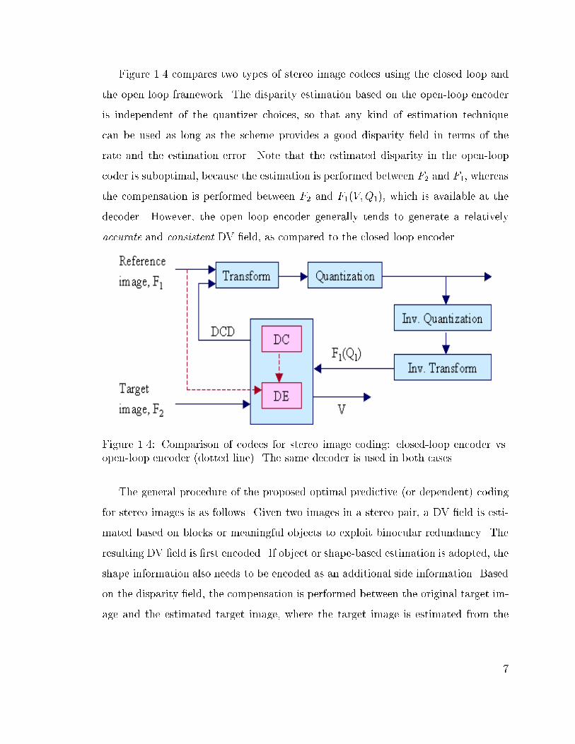
Figure 1.4 compares two types of stereo image codecs using the closed loop and
the open loop framework. The disparity estimation based on the open-loop encoder
is independent of the quantizer choices, so that any kind of estimation technique
can be used as long as the scheme provides a good disparity �eld in terms of the
rate and the estimation error. Note that the estimated disparity in the open-loop
coder is suboptimal, because the estimation is performed between F2 and F1, whereas
the compensation is performed between F2 and F1(V;Q1), which is available at the
decoder. However, the open loop encoder generally tends to generate a relatively
accurate and consistent DV �eld, as compared to the closed loop encoder.
Figure 1.4: Comparison of codecs for stereo image coding: closed-loop encoder vs.
open-loop encoder (dotted line). The same decoder is used in both cases.
The general procedure of the proposed optimal predictive (or dependent) coding
for stereo images is as follows. Given two images in a stereo pair, a DV �eld is esti-
mated based on blocks or meaningful objects to exploit binocular redundancy. The
resulting DV �eld is �rst encoded. If object or shape-based estimation is adopted, the
shape information also needs to be encoded as an additional side information. Based
on the disparity �eld, the compensation is performed between the original target im-
age and the estimated target image, where the target image is estimated from the
7
quantized reference image. Then, the reference image and the DCD frame are trans-
formed, quantized and encoded. At this stage, the bits have to be distributed properly
between the transformed reference image and the di�erence frame. Note that, to opti-
mize encoding e�ciency, the reference image, F1, can not be quantized independently
because the distortion of the target image, D2, depends on the quantization choices
for the reference image along the DV �eld, i:e: F1(Q1; V ). The distribution can be
controlled by adjusting the quantization steps (scales or factors) for both transformed
F1 and DCD frame. At the decoder, �rst the reference image is decoded and then
the target image is reconstructed by adding the disparity compensated frame and the
decoded di�erence frame.
1.3 Main Contribution
The primary aim of this research is to provide e�cient encoding schemes for stereo
images/video within the predictive coding framework, where the dependencies aris-
ing from using a prediction with a quantized reference image complicates an optimal
dependent coding. In the proposed framework, using an open-loop encoding frame-
work, we decouple this complicated joint optimization problem into two independent
optimization problems: (i) \e�cient" disparity estimation and (ii) \optimal" depen-
dent quantization. In this dissertation, \e�cient" means reducing the rate as much
as possible, while maintaining a low distortion, which we assume will correlate with
3D perceptual visual quality. As a result, in the proposed framework, any e�cient
disparity estimation algorithm can be adopted as long as the estimation scheme pro-
vides a good DV �eld in terms of the rate of the DV and the energy of the estimation
error. Note also that we interchangeably use the terms coding and compression. The
proposed schemes are implemented with a JPEG-like codec but they can be easily
modi�ed to use an MPEG-like video codec to encode multiview images/video. A
detailed list of the main contributions of this research follows.
8

� We have made a brief survey on conventional coding schemes for stereo images
and addressed the main coding issues. We have proposed an optimal blockwise
dependent quantization scheme. In the proposed framework, the quantization
parameters are selected simultaneously for blocks in the reference image and
the disparity compensated di�erence frame so as to minimize some averaged
distortion measure, while meeting any applicable bit budget constraints. The
encoding complexity and delay in the dependent quantization framework can be
signi�cantly reduced in the proposed structure by exploiting the predominant
unidirectional property of the binocular dependency3. The experimental results
show that the proposed scheme results in a higher rate being used for the refer-
ence frame (thus improving its MSE performance) that results in higher PSNR
for the target frame as well (even though fewer bits are used). The proposed
quantization scheme can be a benchmark for practical rate control schemes
or aid in developing a fast and e�cient bit allocation strategy. It also can be
used in asymmetric applications such as CD-ROM, DVD and video-on-demand,
which may involve o�ine encoding.
� We also have proposed a fast algorithm for the blockwise dependent quantiza-
tion, based on the assumption of existence of a monotonicity property in the
prediction between the two images in a stereo pair. The experimental results
show that most of the gain can be obtained at a fraction of the complexity, as
compared to the full search scheme.
� We have investigated various disparity estimation/compensation algorithms
and proposed two schemes to overcome well-known limitations of block-based
schemes such as inaccurate disparity estimation and blocking artifacts in the
decoded image at low rate coding. The proposed schemes produce robust and
3In similar problems in motion compensated video only approximate solutions are feasible. Note
that an optimal solution requires considering a whole image, due to 2D dependency between frames
in a video sequences.
9

accurate DV �elds, which in turn increase the encoding e�ciency. The proposed
disparity compensation schemes are based on: (i) �xed size block matching and
(ii) variable size block matching.
� We have proposed a �xed size block-based scheme, modi�ed overlapped block
disparity compensation, that can overcome the drawbacks of conventional �xed
sized block-based methods. The proposed hybrid scheme consists of (i) dispar-
ity estimation using a modi�ed MRF model, i:e: using a smoothness constraint
within a causal neighborhood and (ii) selective overlapped block disparity com-
pensation. The disparity estimation with smoothness constraint results in a
relatively smooth disparity �eld, while maintaining the energy level of the DCD
frame. The selective overlapped block disparity compensation reduces blocking
artifacts in the decoded target image and improves encoding e�ciency, while
reducing the computational complexity of overlapped block disparity compen-
sation schemes. The incorporated half-pixel accuracy further improves the en-
coding e�ciency.
� We have proposed a quadtree-based block segmentation scheme to overcome
inherent limitations of �xed size block-based schemes. The proposed scheme
achieves higher PSNR gain over �xed size block matching by relaxing the one-
vector-per-block assumption. In addition, hierarchical disparity estimation with
smoothness constraints in a causal neighborhood allows a consistent disparity
�eld. The RD cost-based block segmentation improves encoding e�ciency over
conventional variable size block matching. The selective overlapped block dis-
parity compensation for the segmented subblocks reduces blocking artifacts and
thus further improves encoding e�ciency for the DCD frame.
� Finally, we have presented and discussed various possible extensions of this
research in the last Chapter of this dissertation. The extensions include
{ object-oriented hybrid segmentation using stereo images
10

{ rate-distortion based contour coding
{ blockwise dependent quantization for video coding
{ joint estimation of disparity and motion for stereo video
{ multiview image coding and intermediate view generation
1.4 Dissertation Overview
This dissertation is organized as shown in �gure 1.5.
Figure 1.5: Overview of the dissertation.
In Chapter 2, we �rst formulate the stereo image coding problem using the pre-
dictive coding framework and explain that exploiting the \binocular" dependency is
essential in optimizing the overall coding performance. We brie y review 3D and
stereo vision as a background. We also survey various issues on stereo images and
brie y review previous works on stereo image coding.
11

In Chapter 3, we propose a blockwise dependent quantization scheme and explain
how to �nd optimal sets of quantizers for a pair of stereo images, i:e: the reference im-
age and the disparity compensated di�erence frame. The proposed algorithm, based
on dynamic programming, provides the optimal blockwise bit allocation. The RD-
based cost function is de�ned using Lagrangian method. The predominant horizontal
dependency helps construct a compact dependency tree, which is called a trellis, for
each pair of \row of blocks (ROB)," one in the reference image and one in the target
image. The �nite set of admissible quantization scales and the corresponding La-
grangian cost are assigned to the nodes and the branches of the trellis, respectively.
Then, optimal sets of quantizers are searched using the Viterbi algorithm. The same
trellis structure is repeatedly applied for each pair of ROB. We also propose a fast
algorithm that provides most of the gain at a fraction of the complexity.
In Chapter 4, we propose a block-based disparity estimation/compensation
scheme, modi�ed overlapped block disparity compensation, that overcomes the well-
known limitations of conventional �xed size block matching schemes, such as blocking
artifacts or inaccurate estimation. In the proposed scheme, smoothness constraints in
causal neighborhood help us estimate a relatively smoother and more consistent dis-
parity �eld, while maintaining encoding performance for the disparity compensated
di�erence frame. Simultaneously, selective overlapped block disparity compensation
reduces computational complexity of the conventional overlapped matching scheme,
while reducing blocking artifacts. However, block-based methods have inherent lim-
itations in removing the estimation errors, especially along the object boundaries.
These kinds of errors can be reduced by using the variable size block matching and
relaxing the uniform disparity assumption within the block, while keeping consistency
of disparity vector �eld.
As a continuation of Chapter 4, in Chapter 5, we therefore introduce a variable size
block-based scheme, quadtree-based block segmentation, to further improve encoding
e�ciency along object boundaries. In the proposed scheme, the MRF model-based
12
disparity estimation allows consistent estimation even in small blocks and the RD
cost-based block segmentation improves encoding e�ciency. In addition, the selec-
tively applied overlapped disparity compensation further improves encoding e�ciency.
In all the proposed schemes, the encoding e�ciency is improved mainly by reducing
the entropy of the disparity compensated di�erence along the object boundaries,
while reducing the rate for the disparity �eld using hierarchical smooth constraint.
The improved encoding performance also results from selective overlapped disparity
compensation.
Finally, the summary and possible extension of this research are brie y addressed
in Chapter 6.
13

Chapter 2
3D and Stereo Image Coding
A number of research results have been reported which demonstrate the advantages
of stereoscopic images/video over conventional monoscopic image/video [2]. In gen-
eral, objects are seen more sharply in 3D images than in 2D images because 3D
images enable humans to perceive clear contours between objects and background
using binocular depth information. However the cost for this increased realism is
the doubling of the amount of data necessary to transmit or store. In general, ef-
�cient transmission can be achieved by exploiting spatial and temporal redundancy
in each sequence. In the case of stereo images/video, the e�ciency can be further
improved by exploiting binocular dependencies in stereo pairs. Also note that, to
allow compatibility with 2D displays, transmission of stereoscopic images/video over
existing channels may require very low rate coding to accommodate the additional
image/stream, while maintaining the quality of the reference image/sequence. In this
chapter, we describe 3D and stereo vision as a background. We brie y review the
main issues and the previous work on stereo image coding.
14

2.1 Brief History of 3D
In 300 B.C. Euclid recognized that depth perception is obtained when each eye re-
ceives simultaneously one of two similar images [16]. In the early 1830s, the Wheat-
stone Viewer1 created the illusion of three dimensions using pairs of hand-drawn
illustrations. The subsequent invention of photography in 1839 allowed for stereo
photographs. Then, the stereo photographs became popular in the late 19th century
after the creation of the re�ned and reduced version of Wheatstone Viewer2. The
popularity of 3D peaked around the turn of the century. Ever since, 3D has been an
important part of the history of photography and �lm3.
The �rst 3D �lm showing scenes of New York and New Jersey premiered in New
York City in 1915. Subsequently, 3D imaging was revitalized through the 30's and
40's. In 1933, the Tru-Vue Company introduced a stereoscope using a 35mm �lm.
In 1939, Chrysler Motors paved the way for the projection of full-color 3D �lm by
showing a 3D �lm using polarized material without color distortion. With the inven-
tion of the television in 1939 (London), electronic versions of 3D (based on anaglyph
method) were prompted in 19424. However, in the 1950s, due to the disadvantages of
the anaglyphs methods, 3D survived mostly in the cinema, rather than TV. The 3D
�lm was one of the great hopes for the movie industry to reverse the decline in the
number of viewers lost to TV. However, 3D �lm also has not been widely accepted
due to its drawback that viewers have to wear uncomfortable special glasses and thus
can experience headaches.
In the early 1990s stereoscopic methods gained a renewed interest based on the
recent developments of autostereoscopic display system5. For several decades, various
1The �rst stereoscope was invented by British scientist Sir Charles Wheatstone.2The hand-held versions, the Brewster Stereoscope and the Holmes stereoscope, were invented
by Sir Davis Brewster in 1847 and by Oliver Wendell Holmes in 1862, respectively.3Refer http://www.afc.gov.au/resources/online/afc loi/presentations/gary+w.html4The �rst experimental stereoscopic television program was broadcasted by SelectTV, LA, CA,
USA in 1953.5Refer http://www.cl.cam.ac.uk/Research/Rainbow/projects/asd.html
15

e�orts have been made to develop practical 3D systems but 3D technologies including
holography have not met the demands for realistic displays. Most of the e�orts have
gone into two-view stereoscopic systems with special glasses, which have limitations
in terms of providing high quality or comfortable viewing. Such systems have proved
e�ective in some scienti�c applications and, to a limited extent, in 3D wide screen
cinema, such as IMAX(R) 3D6. However, through the 90's, considerable advances in
3D display technologies and innovations in the related �elds are opening a new way
for the 3D systems without special glasses.
In particular, several 3DTV projects bring together both signal processing and
human factors. In Europe, research on 3DTV has been initiated by several projects,
such as COST2307 and DISTIMA8, which aimed to develop a system for captur-
ing, coding, transmitting and presenting digital stereoscopic image sequences. The
projects had been followed up by another project, PANORAMA9, which aims to en-
hance the visual information exchange in telecommunications with 3D telepresence.
Other noteworthy e�orts have been made by the 3D HDTV project of NHK10.
2.2 3D Perception and Stereo Geometry
So far, stereo images/video have been intensively studied in the �eld of computer
vision because stereoscopic viewing is one basic and popular way to perceive the
environment in 3D [16, 17]. The two images in a stereo pair are called stereoscopic
or stereo images. A sequence of stereoscopic images is called stereo video. The
main limitation of stereo images/video is that the viewing position is bound to the
position of cameras. In general, 3D imaging systems provide more freedom in viewing
position than stereoscopic displays. However, the term \stereoscopic" and \3D" are
6Refer http://www.theatres.sre.sony.com/imax/across/history/history.html7Refer http://www.fub.it/cost230/welcome.htm8Refer http://www.tnt.uni-hannover.de/project/eu/distima/overview.html9Refer http://www.tnt.uni-hannover.de/project/eu/panorama/10Refer http://www.strl.nhk.or.jp/results/annual96/3-1.html
16

used interchangeably because stereoscopic images/video can be easily extended into
3D.
In general, 3D perception is based on various depth cues such as light, shade,
relative size, motion, occlusion, texture gradient, geometric perspective, disparity,
etc. However, one of the most e�ective cues is the binocular depth perception based
on the fact that the depth perception is obtained by viewing a scene from slightly
di�erent viewing positions. Humans perceive a scene in 3D as follows. First, the scene
in 3D real world is projected onto the retina as a 2D image, where each eye views
a slightly di�erent scene. Note that the 3D depth information is lost at this stage.
Then, the primary visual cortex in the brain fuses the stereo pair by a stereopsis and
a prior knowledge on the 3D world. Finally, humans perceive the feeling of depth by
reconstructing 3D from 2D.
Similarly, in 3D imaging systems, the function of the eyes is taken over by stereo
cameras that capture a scene from slightly di�erent positions. The depth information
can be obtained based on stereo vision techniques where the depth information is
calculated by triangulation with the disparity, the relative displacement, and the
geometry of the stereo camera. The procedure of estimating the disparity �eld has
been known as the correspondence problem or disparity estimation.
To generate a stereo video sequence, two video cameras are placed in parallel to
take images from slightly di�erent perspective. Figure 2.1 shows the basic structure
for stereo image formation and stereo camera geometry. The center of the lens is
called the camera focal center and the axis extending from the focal center is referred
to as the focal axis. The line connecting the focal centers is called the baseline, b.
The plane passing through an object point and the focal centers is the epipolar plane.
The intersection of two image planes with an epipolar plane makes the epipolar line.
Let (X; Y; Z) denote the real world coordinates of a point. The point is projected
onto two corresponding points, (xl; yl) and (xr; yr), in the left and right images. The
17
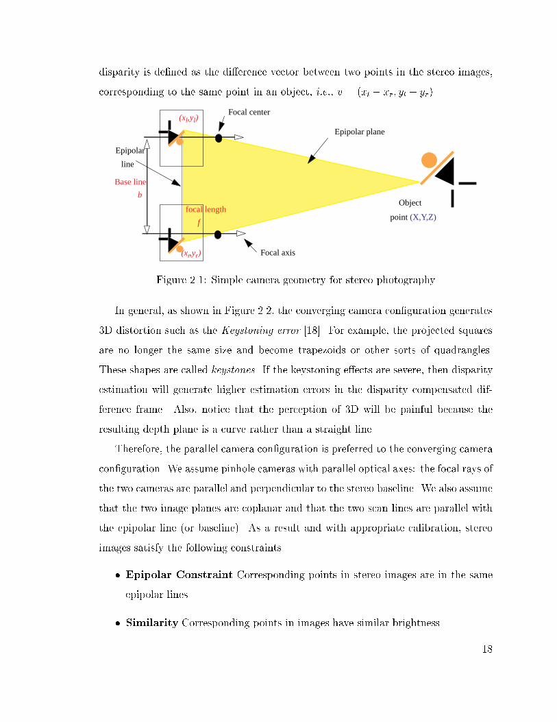
disparity is de�ned as the di�erence vector between two points in the stereo images,
corresponding to the same point in an object, i:e:, v = (xl � xr; yl � yr).
Base line
(xl,yl)
(xr,yr)
Object
point (X,Y,Z)
Epipolar plane
Focal axis
Focal center
Epipolar
line
b
focal length
f
Figure 2.1: Simple camera geometry for stereo photography
In general, as shown in Figure 2.2, the converging camera con�guration generates
3D distortion such as the Keystoning error [18]. For example, the projected squares
are no longer the same size and become trapezoids or other sorts of quadrangles.
These shapes are called keystones. If the keystoning e�ects are severe, then disparity
estimation will generate higher estimation errors in the disparity compensated dif-
ference frame. Also, notice that the perception of 3D will be painful because the
resulting depth plane is a curve rather than a straight line.
Therefore, the parallel camera con�guration is preferred to the converging camera
con�guration. We assume pinhole cameras with parallel optical axes: the focal rays of
the two cameras are parallel and perpendicular to the stereo baseline. We also assume
that the two image planes are coplanar and that the two scan lines are parallel with
the epipolar line (or baseline). As a result and with appropriate calibration, stereo
images satisfy the following constraints.
� Epipolar Constraint Corresponding points in stereo images are in the same
epipolar lines.
� Similarity Corresponding points in images have similar brightness.
18

Figure 2.2: Conversing camera geometry for stereo photography
� Uniqueness A point in an image corresponds to only one point in the other
image because one point in an object is projected onto only one point in each
image.
� Continuity and Ordering Under the assumption of smooth object surfaces,
the disparity varies continuously (or smoothly) in most parts of the image except
at object boundaries or occlusion areas. The disparity is also in order except
for the occlusion areas.
Finally, 3D information (X; Y; Z) can be computed by triangulation with binocular
disparity and a given camera geometry as follows.
X =b(xl + xr)
2� jvj; Y =
b(yl + yr)
2� jvj; Z =
bf
jvj; (2.1)
where b represents the baseline and f denotes the camera focal length. As can be
seen in (2.1), the disparity can be considered as a relative depth because the disparity
is inversely proportional to the depth. If the parallel axis constraint is satis�ed, the
search area for correspondence is restricted to a line and the matching process is
19

accelerated signi�cantly, i:e, (vx; vy) = (0; yl � yr). By broadening the baseline, the
accuracy of the distance measure can be increased but the common areas in the two
images are decreased.
In real systems, there may be luminance di�erences between images in a stereo
pair because the characteristics of the stereo cameras may be slightly di�erent. In
addition, there are some areas that only appear in one image of the stereo pair due
to the stereo camera geometry, even though we assume the parallel axis constraint
is met. Figure 2.3 shows an example of this phenomenon in stereo images, which is
called occlusion.
image plane Object
Camera
invisiblearea Occluded
areaSelf-occlusion
Figure 2.3: Occlusion e�ects. There are some regions that appear only in one image
of the stereo pair due to the stereo camera geometry.
In general, the occlusion makes disparity estimation complicated. Figure 2.4 shows
the disparity �eld variation according to the occlusion e�ects.
2.3 Issues in Stereo Image Coding
2.3.1 Disparity Correspondence
Most research e�orts in stereo vision have been focused on an accurate disparity
estimation11. As explained, several factors make the correspondence problem di�-
cult. To overcome those problems and to estimate an accurate disparity �eld, several
11A comprehensive review on computational stereo can be found in [19].
20

xL
xR
Disparity
Occlusion
dy
xL
Undefined
Figure 2.4: Disparity variation according to occlusion areas
schemes have been proposed, which can be grouped into two categories: (i) area-based
and (ii) feature-based approaches.
In area-based approaches, pixels or regions are used to measure the similarity be-
tween stereo pair [20,21]. They yield dense disparity �elds but tend to fail because of
local ambiguities in the correspondence. Various improved estimation techniques have
been proposed to overcome these problems. Regularization methods with smoothness
constraints weaken the noise problem but they oversmooth the discontinuities such
as those occurring at object boundaries [22{24]. Markov random �eld (MRF) mod-
els with various constraints reduce the oversmoothing problem using soft smoothness
constrained with line processes [25{28]. Though the bene�ts of including disconti-
nuities in the energy function are signi�cant, they require excessive computational
power to solve highly nonlinear (stochastic) optimization problems.
In feature-based methods, local cues (such as edges, lines, corners) have been used
in disparity estimation [29{33]. They provide a robust disparity �eld because the
features are more stable image properties than the original intensity image. However,
feature-based schemes may work only if features are extracted in both images. They
also may require interpolation to estimate a dense disparity �eld, because the disparity
can be estimated only at the feature positions. However, interpolation is another
complicated procedure due to its ill-posedness [34]. Phase-based disparity estimation
21

is another method, which also requires additional steps to ensure the exclusion of
regions with ill-de�ned phase [35, 36].
Though many disparity estimation techniques developed in the computer vision
communities may be applicable to stereo image coding, the direct adoption of those
techniques may not be e�ective for various reasons. For example, the main emphasis
of stereo vision (or/and motion analysis) has been on the accurate estimation of
disparity (or/and motion) in order to reconstruct the 3D structure of the scene. An
accurate displacement estimation is a key issue in stereo vision, because a disparity
vector corresponds to the distance between cameras and the corresponding object
point in the scene. However, the main focus of coding is the tradeo� between rate
and distortion. Thus the goal of stereo image/video coding is not to estimate the
true disparity but rather to achieve a high compression ratio. Therefore, it may not
be worthwhile to compute a dense disparity �eld if the cost of handling (transmitting
or storing) the disparity vector �eld is too high.
As a compromise, in coding of stereo images/video, �xed size block matching
(FSBM) has been widely used, even though the true disparity/motion �elds are obvi-
ously not blockwise constant [8,12,37]. FSBM-based methods are simple to implement
and e�ective in terms of rate-distortion (RD) because they exploit the redundancy
on the disparity �eld with a regular structure, which does not require additional
information for the structure of the disparity �eld.
2.3.2 A Brief Review: Stereo Image Coding
As explained, higher encoding performance can be achieved by exploiting the inherent
redundancy between two images in a stereo pair, as compared to independent coding.
A simple coding for stereo images is to encode the two images independently, using
conventional coding schemes or using 3D DCT [38]. Dinstein et al. also proposed
a compression method based on the frequency domain relationship without dispar-
ity estimation [15]. A simple modi�cation to uncorrelate two images is to encode
22

an image and the di�erence between two images. However, this method is not so
e�cient because each object in the scene has di�erent disparity. Therefore, further
improvement can be achieved by adopting predictive coding, where a disparity vector
�eld and disparity compensated di�erence frame are encoded.
Due to the similarity between stereo images and video, many of the intuitions and
techniques used in video coding are applicable to stereo image coding [39]. Predictive
coding with motion estimation in video coding increases the coding gain by exploit-
ing the temporal dependency. It is possible because consecutive images in a video
sequence tend to be similar. In general, disparity estimation is similar to motion
estimation in the sense that they both are used to exploit the similarity between two
(or more) images in order to reduce the bit rate.
However, the motion estimation schemes developed in video coding may not be
e�cient unless geometrical constraints for stereo imaging are taken into account. For
example, if the cameras meet the epipolar constraint12, the direction of the disparity
is predominantly horizontal13. In comparison, motion vectors can take any direction
in the 2D plane. This property simpli�es the disparity estimation process, but other
distinctive features of stereo images, e:g: occlusion, noise and 3D distortion (such
as Keystoning) resulting from the stereo camera geometry, signi�cantly degrade es-
timation/compensation e�ciency [17, 18]. Note that, unlike video sequences, stereo
images are projected onto two cameras and thus intensity levels between two images
in a stereo pair tend to be slightly di�erent. Note also that the occlusion areas are
generated by all objects in the scene and not only moving objects as in motion estima-
tion, as long as the objects are located at slightly di�erent position in the 3D scene.
As a result, the DCD may have high residual energy and thus the DCD frame may
require relatively more rate as compared with the displaced frame di�erence (DFD)
12This constraint implies that the focal rays of the two cameras are parallel and perpendicular to
the stereo baseline.13If the cameras met the epipolar constraint, a particular object will appear in the two images
with only a horizontal shift between its respective position. The epipolar constraint implies that
focal rays of the two cameras are parallel and perpendicular to the stereo baseline
23
in video coding. Consequently, the e�ciency of disparity compensated coding can be
greatly reduced due to those features and the coding gain of disparity compensation is
relatively smaller over independent coding, as compared to motion compensation [38].
Disparity estimation is one of the key steps in the stereo coding, because it
helps to exploit the similarity along the disparity in the process of disparity estima-
tion/compensation. In the predictive coding framework14, the redundancy is reduced
by compensating the target image from the reference image along the disparity vec-
tors. Since the pioneering work by Lukacs [12], the most widely used coding methods
for stereo images have been FSBM-based predictive coding15.
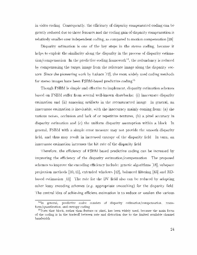
Though FSBM is simple and e�ective to implement, disparity estimation schemes
based on FSBM su�er from several well-known drawbacks: (i) inaccurate disparity
estimation and (ii) annoying artifacts in the reconstructed image. In general, an
inaccurate estimation is inevitable, with the inaccuracy mainly coming from: (a) the
various noises, occlusion and lack of or repetitive textures, (b) a pixel accuracy in
disparity estimation and (c) the uniform disparity assumption within a block. In
general, FSBM with a simple error measure may not provide the smooth disparity
�eld, and thus may result in increased entropy of the disparity �eld. In turn, an
inaccurate estimation increases the bit rate of the disparity �eld.
Therefore, the e�ciency of FSBM-based predictive coding can be increased by
improving the e�ciency of the disparity estimation/compensation. The proposed
schemes to improve the encoding e�ciency include: genetic algorithms [18], subspace
projection methods [40, 41], extended windows [42], balanced �ltering [43] and RD-
based estimation [44]. The rate for the DV �eld also can be reduced by adopting
other lossy encoding schemes (e:g: appropriate smoothing) for the disparity �eld.
The central idea of achieving e�cient estimation is to reduce or weaken the various
14In general, predictive codec consists of disparity estimation/compensation, trans-
form/quantization, and entropy coding.15Note that block, rather than feature or pixel, has been widely used, because the main focus
of the coding is in the tradeo� between rate and distortion due to the limited available channel
bandwidth.
24
noise e�ects by using useful constraints such as smoothness. The noise e�ects can
be reduced by exploiting the correlation among neighboring disparity vectors. In
general, the reduction of bit rate for the disparity �eld can be achieved by estimating
a relatively smooth disparity �eld. Note however that, in order to maintain or improve
encoding e�ciency, a careful tradeo� is required between smoothness of the disparity
�eld and the entropy of the DCD frame. For example, the disparity vector has to
be selected to reduce the entropy for the disparity �eld, if it is similar to those of its
neighbor blocks and it does not increase prediction error \too much."
In addition, an e�cient method to deal with the DCD frame is essential to achieve
low rate encoding because higher energy occurs along object boundary and occlusion
region. For example, if the block includes object boundaries, block-based methods
may su�er from visual artifacts at low bit rates, where only a few bits are assigned to
the DCD frame. In particular, for images encoded at low rate coding, these artifacts
usually appear along the block boundaries in the decoded target, as shown in Figure
2.5. These blocking errors can be very annoying because the human visual system
(HVS) is sensitive to object boundaries, which are usually related to abrupt intensity
changes. These artifacts result from di�erent error sources: (i) disparity discontinuity
due to our use of an error criterion considering only the DCD, (ii) the assumption
of one vector per �xed size of block, and (iii) the quantization e�ect of the reference
image, i:e:, block edge may be copied and pasted. Therefore, using overlapped block
disparity compensation reduces the energy level of the disparity estimation errors
without increasing the bit rate for the disparity �eld. In particular, the rate of the
DCD frame can be reduced by combining both the subpixel accuracy and overlapped
block disparity compensation [45].
Another approach to improve encoding e�ciency is relaxing the one-vector-per-
block assumption, which can overcome the disadvantage of FSBM, e:g: the annoying
blocking artifacts in the reconstructed image. In FSBM, the higher prediction errors
occur because the block boundaries do not coincide with the object boundaries. By
25

Target Image
Occlusion
Energy
Block
Reference Image
Figure 2.5: Various types of error in the DCD frame.
reducing the block size, the estimation error can be reduced, but as the block size
becomes smaller the associated overhead (bit rates) required to transmit the disparity
�eld becomes too large. In addition, smaller blocks frequently fail to provide good
matching results because the estimation is subject to various noise e�ects and thus a
less homogeneous disparity �eld is generated. Note that pixel-based estimation is the
best way to reduce the entropy of the DCD frame. However, this comes at the cost of
an expensive increase in the overhead necessary to represent the resulting disparity
�eld. Meanwhile, increasing the block size increases the robustness against noise in
the disparity estimation, but it also increases the magnitude of the estimation error.
A good solution to this dilemma is a hierarchical (or sequential) block segmentation
[46, 47].
Segmenting a block with higher prediction error into smaller subblocks can further
reduce the rate of the DCD frame. The quadtree-based methods have been commonly
used to encode the resulting disparity �eld [48{52]. However, the cost for reduced
energy of the DCD frame is the increased side information of the disparity �eld.
In order to increase coding gain over the block-based methods, segmentation-based
26

algorithms have to represent the segmentation information (quadtree or boundary)
and the corresponding disparity in an e�cient manner.
A hybrid segmentation approach, which combines the disparity estimation based
on the hierarchical block segmentation and the disparity �eld segmentation using
an MRF model, can further improve encoding e�ciency [53]. Also, the pixel-based
disparity estimation with an arbitrary shape-based coding can be used to reduce the
blocking artifacts [54,55]. In general, the process of segmentation simultaneously pro-
duces useful intermediate information for various applications such as scene analysis,
synthesis, or generation [56]. Note however that the segmentation and its description
cost are too expensive, compared to block-based schemes [3, 4, 53, 57].
In general lossy coding scenarios, quantization is an equally important problem.
However, with few exceptions (e:g: [58]), the quantization and the bit allocation
issues speci�c to stereo image coding have rarely been considered. Note that available
conventional quantization or bit allocation schemes are mainly developed based on the
assumption of completely decoupled encoding steps, e:g: the reference image and the
target image in a stereo pair are quantized independently, and thus overall optimality
cannot be guaranteed. Obviously, in the predictive coding framework, dependent
quantization can further optimize the coding performance by selecting two sets of
quantizers reducing quantization errors for the reference image and the DCD frame,
while maintaining the total bit rate less than that of the allowed bit budget [39, 59].
A noteworthy e�ort in stereo image coding research has been generating interme-
diate views to provide additional freedom of viewing angles, without increasing rates.
In general, intermediate view at the decoder can be synthesized by spatial interpola-
tion using two decoded images in a stereo pair and disparity information. Therefore,
to increase the quality of the synthesized intermediate image, a reliable occlusion, as
well as disparity, estimation is essential [53, 60].
Another challenging area is measurement of 3D distortion. In 3D imaging systems,
humans observe 3D scenes by combining two images together, instead of observing
27
each image independently. Recently, image coding schemes incorporating the charac-
teristics of human visual system (HVS) have been investigated. The spatial frequency
sensitivity of HVS is measured and model as modulation transfer function (MTF) [61].
The MTF has been incorporated into transform coding and used to adjust quantiza-
tion step sizes [62]. In addition, the spatio-temporal characteristics of HVS have been
measured and modeled [63]. However, the measurement of 3D perception of HVS has
yet to be actively researched. Obviously, simply combined distortion, D1 +D2, may
not re ect the exact perceptual quality [64]. According to the suppression property
of HVS, relatively lower bit rate for the target image may not signi�cantly degrade
the 3D perceptual quality [38].
2.3.3 Fixed Size Block Matching
2.3.3.1 Disparity Estimation
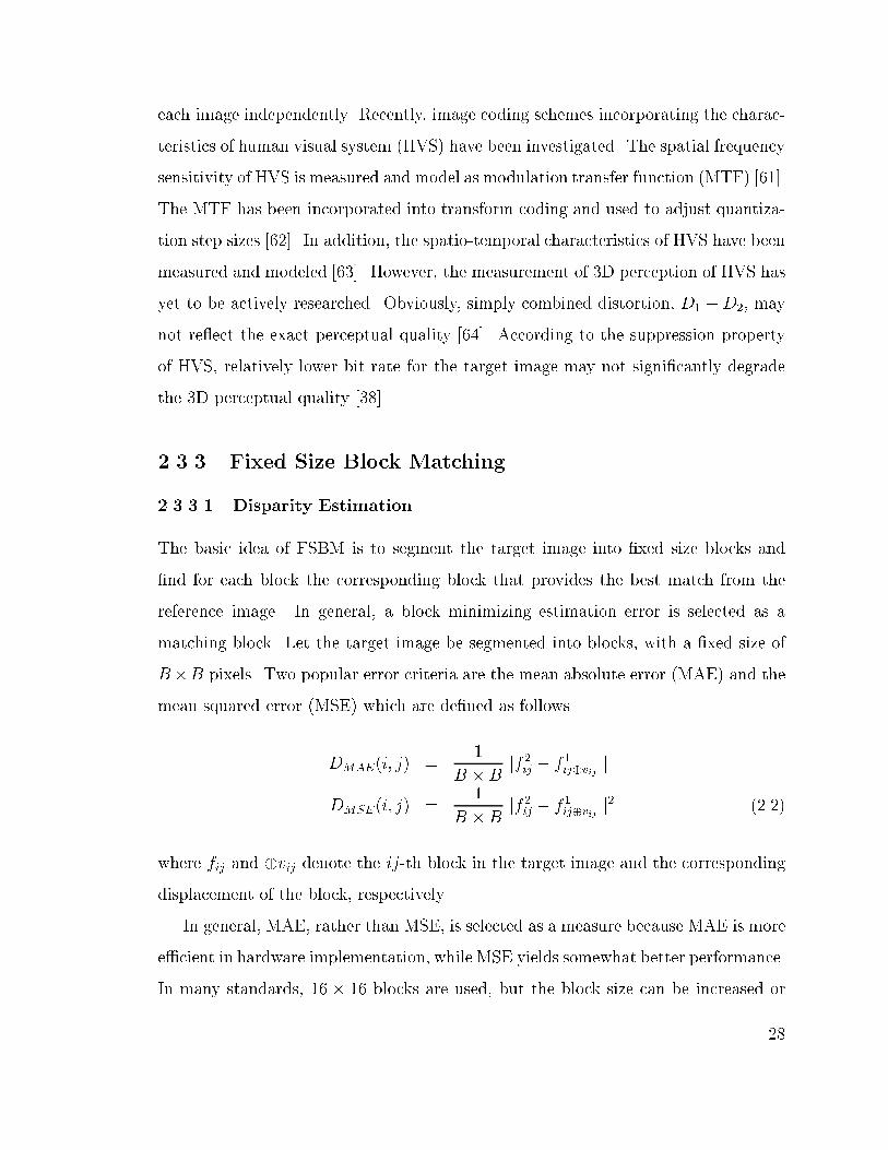
The basic idea of FSBM is to segment the target image into �xed size blocks and
�nd for each block the corresponding block that provides the best match from the
reference image. In general, a block minimizing estimation error is selected as a
matching block. Let the target image be segmented into blocks, with a �xed size of
B�B pixels. Two popular error criteria are the mean absolute error (MAE) and the
mean squared error (MSE) which are de�ned as follows
DMAE(i; j) =1
B � Bjjf
2ij � f
1ij�vij
jj
DMSE(i; j) =1
B � Bjjf
2ij � f
1ij�vij
jj2 (2.2)
where fij and �vij denote the ij-th block in the target image and the corresponding
displacement of the block, respectively.
In general, MAE, rather than MSE, is selected as a measure because MAE is more
e�cient in hardware implementation, while MSE yields somewhat better performance.
In many standards, 16 � 16 blocks are used, but the block size can be increased or
28
reduced according to the characteristics of the images. The most straightforward
block matching method is the full search within the search window, known as the
exhaustive search. It guarantees an optimal solution for given sizes of block and
search window, if only the DCD frame is considered.
However, the advantages of FSBM may not be so clear once the overall coding
system is considered together. In addition, a more consistent and exact disparity
�eld is necessary for the application of intermediate scene generation, which provides
look-around capability, because there is no available DCD frame in synthesizing the
images corresponding to the intermediate viewpoints.
2.3.3.2 Disparity Compensated Di�erence
After disparity estimation/compensation, the di�erence between the disparity com-
pensated and the original target image is generated. The di�erence is called disparity
compensated di�erence (DCD), which has to be stored or transmitted together with
a disparity �eld to improve the quality of the decoded target image. As explained in
Section 2.3.3, the disparity estimation based on FSBM with MSE (or MAE) results
in non-zero residual images containing high frequency components, especially in the
block where the disparity estimation/compensation fails.
For DCD coding, several di�erent approaches can be used such as pulse code
modulation (PCM), di�erential PCM (DPCM), vector quantization, transform coding
and subband coding. The simplest way is PCM, where the value of each pixel in
DCD frame is quantized and encoded independently, without considering values of
neighboring pixels. However, PCM is ine�cient when neighboring pixels have strong
correlation. DPCM exploits inherent spatial redundancy by predicting the current
value using values of neighboring pixels. The di�erence between the value of the
current pixel and the predicted value is quantized and encoded. In PCM or DPCM, an
optimal scalar quantizer (SQ), such as Lloyd-Max or entropy constrained quantizer, is
required to optimize the encoding e�ciency [65]. Given the number of reconstruction
29

levels, the indices of reconstruction levels are transmitted or stored. Though DPCM
is relatively simple to implement, the achievable compression ratio is not so high.
A more e�cient approach is to group pixels into vectors and to quantize them
jointly. Note that usually this so called vector quantization (VQ) has been applied
jointly with a transform or a subband coding scheme. The main advantage of VQ
over SQ stems from utilizing correlation between pixels. However, �nding an optimal
codebook, i:e: reconstruction levels, is complicated.
The discrete cosine transform (DCT) is the most widely used transform for image
and video coding. It has been so successful that, in current image/video coding
standards, the DCT is employed for encoding of the DCD frame as well as the intra
frame. Note that the basis of DCT are image independent but DCT approximate
the optimum transform, Karhunen-Loeve transform (KLT), for natural images that
can be modeled with a �rst order Gauss-Markov process (with higher correlation,
� > 0:9). Chen et al. showed that the KLT, for the motion compensated di�erence
frame is identical to that for the luminance image in spite of di�erent statistical
characteristics and, as a result, the DCT remained a near optimum transform for
the motion compensated di�erence frame [66]. Another advantage of DCT is the
availability of a fast implementation. Note however that the main weakness of the
DCT is the fact it causes blocking artifacts at low rate coding.
Other noteworthy e�orts include exploiting the statistical characteristics of DCD
frame. The characteristics of motion compensated di�erence (MCD) frames have
been studied [62, 66{72] and those works can provide insights into the encoding of
the DCD frame. Based on observed statistics, many adaptive quantization schemes
(with transform coding) have been reported. Connor et al. discussed the statistical
characteristics of the MCD frame using the autocorrelation properties based on MRF
theory [67]. Gonzalez et al. developed a minimal adaptive quantization algorithm
operating in DCT domain. The algorithm is designed to optimize image quality by
adapting a quantization scale factor to the local characteristics of the video while
30

keeping the average output bit rate [73]. Puri et al. developed a strategy for an
adaptive quantization method using a model for perceptual quality and bit rate [71].
Chun et al. described an adaptive quantization algorithm for video sequence coding
by applying the perceptual weights according to the block-based visual activity in the
DCT domain [72]. Stiller et al. proposed a Laplacian pyramid coding for the MCD,
where they employed the classical Laplacian pyramid, a tree growing bit allocation
strategy and the subsequent vector quantization [74]. Muller et al. proposed an
embedded pyramid coding of MCD based on Shapiro's zerotree coding algorithm
[75, 76].
Needless to say, a more precise modeling of the DCD frame for stereo image/video
coding is very important to improve the quality of the coded image, especially at low
rate coding. For stereo image coding, Moellenho� et al. reported on specialized
transform coding for the DCD frame, where they modi�ed a quantization matrix and
then the scanning order [58].
2.3.4 Variable Size Block Matching
Due to its simplicity and robustness, FSBM has been widely used in many video
coding algorithms, including those based on standards16. However, as explained in
previous section, FSBM has well-known drawbacks such as blocking artifacts and in-
accurate estimation. An extreme example of FSBM would be a pixel based approach,
which allows the reduction in entropy of the DCD frame, while increasing the rate of
the disparity �eld by estimating a dense disparity �eld.
The basic idea of variable size block matching (VSBM) is to tradeo� between an
e�cient estimation/compensation and representation of the disparity �eld and the
resulting DCD frame. The quadtree (Qtree) is commonly used, because the Qtree
is e�cient in hierarchically estimating and representing the disparity �eld [77]. An
16One exception is H.263, which allows splitting 16� 16 block into 8� 8 block in the \advanced
prediction mode."
31

image or a block is assigned to a Qtree. Then, the block is segmented into four
subblocks according to a given criterion. The segmentation is repeatedly applied
until the size of subblock reaches 1�1 or the criterion is met. The resulting disparity
�eld is encoded using DPCM.
Another promising approach is region matching, instead of block matching, which
allows more e�cient estimation by considering complex displacement. Obviously, re-
gion or object-based schemes are attractive because they allow the addition of various
object-based functionalities. Note however that the cost of these more sophisticated
schemes is the increase in computational complexity.
2.4 Tools
2.4.1 Rate Distortion Theory
In this Section we introduce some basic concepts of rate-distortion (RD) theory, which
will be useful for the remainder of the dissertation. The source coding theorem states
that the entropy of a source X, H(X) = �Pp(X)log2P (X), is the minimum rate
at which a source can be encoded without information loss, and the channel coding
theorem states that the rate of the source need to be smaller or equal to C for error free
transmission over a channel with capacity C. Meanwhile, the RD theory represents
the lower bound on the rate with a given average distortion or vice versa. Based
on the RD theory the performance bound of lossy data compression schemes can be
found. Note however that RD theory does not provide methods to achieve the bound.
A detailed introduction can be found in [78].
Let a stereo pair in a stereo video sequence be a correlated random processes,
i:e: (F1; F2). Then, according to Shannon's �rst theorem [79], the achievable bound
of the minimum rate is H(F1; F2) = H(F1) + H(F2jF1). Let R and D denote rate
and distortion of an image, respectively. Then, H(F1) � R(F1) and H(F1; F2) �
32
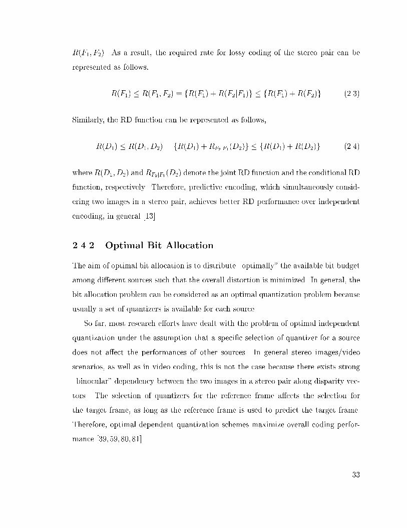
R(F1; F2). As a result, the required rate for lossy coding of the stereo pair can be
represented as follows,
R(F1) � R(F1; F2) = fR(F1) +R(F2jF1)g � fR(F1) +R(F2)g (2.3)
Similarly, the RD function can be represented as follows,
R(D1) � R(D1; D2) = fR(D1) +RF2jF1(D2)g � fR(D1) +R(D2)g (2.4)
where R(D1; D2) and RF2jF1(D2) denote the joint RD function and the conditional RD
function, respectively. Therefore, predictive encoding, which simultaneously consid-
ering two images in a stereo pair, achieves better RD performance over independent
encoding, in general [13].
2.4.2 Optimal Bit Allocation
The aim of optimal bit allocation is to distribute \optimally" the available bit budget
among di�erent sources such that the overall distortion is minimized. In general, the
bit allocation problem can be considered as an optimal quantization problem because
usually a set of quantizers is available for each source.
So far, most research e�orts have dealt with the problem of optimal independent
quantization under the assumption that a speci�c selection of quantizer for a source
does not a�ect the performances of other sources. In general stereo images/video
scenarios, as well as in video coding, this is not the case because there exists strong
\binocular" dependency between the two images in a stereo pair along disparity vec-
tors. The selection of quantizers for the reference frame a�ects the selection for
the target frame, as long as the reference frame is used to predict the target frame.
Therefore, optimal dependent quantization schemes maximize overall coding perfor-
mance [39, 59, 80, 81].
33
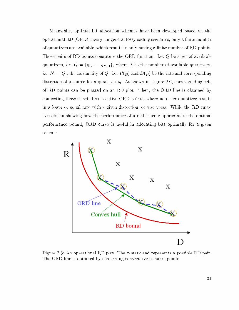
Meanwhile, optimal bit allocation schemes have been developed based on the
operational RD (ORD) theory. In general lossy coding scenarios, only a �nite number
of quantizers are available, which results in only having a �nite number of RD-points.
Those pairs of RD points constitute the ORD function. Let Q be a set of available
quantizers, i:e: Q = fq0; � � � ; qN�1g, where N is the number of available quantizers,
i:e: N = jQj, the cardinality of Q. Let R(qi) and D(qi) be the rate and corresponding
distortion of a source for a quantizer qi. As shown in Figure 2.6, corresponding sets
of RD points can be plotted on an RD plot. Then, the ORD line is obtained by
connecting those selected consecutive ORD points, where no other quantizer results
in a lower or equal rate with a given distortion, or vise versa. While the RD curve
is useful in showing how the performance of a real scheme approximate the optimal
performance bound, ORD curve is useful in allocating bits optimally for a given
scheme.
Figure 2.6: An operational RD plot. The x-mark and represents a possible RD pair.
The ORD line is obtained by connecting consecutive o-marks points.
34
2.4.3 Lagrangian Optimization
An optimal solution to the bit allocation problem can be solved using Lagrangian
multiplier approach [82]. Lagrangian multiplier method is a well-known mathematical
tool to solve constrained optimization problems in a continuous framework. Note that
for a discrete number of operating points, the Lagrangian method �nds a solution
lying on the convex hull, rather than on the ORD line.
Let the rate and distortion of each block depend on the quantization selection.
Then, the rate and the distortion functions are de�ned as R(Q) =P
(ij)2 r(qi) and
D(Q) =P
(ij)2 d(qi), respectively.
For a given bit budget Rbudget an optimal set of quantizers that solves this problem
is,
Q� = argmin
QD(Q); subject to R(Q) � Rbudget (2.5)
The constrained problem can be transformed into an unconstrained problem using
a Lagrange multiplier �. For any � > 0, an optimal solution Q�(�) to the uncon-
strained problem is
Q�(�) = argmin
QfD(Q) + �R(Q)g (2.6)
A remaining problem is how to �nd an optimal �� to optimize the quantization
e�ciency. For �2 > �1, by the optimality of Q�(�1) with R(Q�(�1)) > R(Q�(�2)),
D(Q�(�1)) + �1R(Q�(�1)) � D(Q�(�2)) + �2R(Q
�(�2)). By solving for �1 and �2,
�2 �D(Q�(�1))�D(Q�(�2))
R(Q�(�1))� R(Q�(�2))� �1 (2.7)
Therefore, the ratio of the changes is bounded between two multiplier, �1 and �2. Note
that R(Q�(�)) and D(Q�(�)) are, respectively, a nonincreasing and nondecreasing
function of the Lagrangian multiplier �. Therefore, with a pair of two initial �'s,
(�1; �2), bisection method starts, i:e: R(Q�(�1)) � Rmax � R(Q�(�1)), where Rmax is
the target rate. By selecting a �̂ = �1+�22
, the initial interval is bisected. Then, �1 = �̂
35

if R(Q�(�̂) � Rmax and �2 = �̂, otherwise. By repeating this procedure, the bound is
getting tighter and tighter. However, the bisection scheme has to be stopped using a
threshold value � (> 0), because there might not exist � satisfying R(Q�(�)) = Rmax.
Note that R is de�ned on the �nite set of quantizers Q.
The Lagrangian method is not always optimal because, as shown in Figure 2.6,
the ORD line is not necessarily convex. Note that the Lagrangian method only �nds
the convex approximation, while a direct exhaustive search of constrained problem
results in an optimal solution.
2.4.4 Viterbi Algorithm
The Viterbi algorithm (VA) is a deterministic forward dynamic programming scheme,
which solves an constrained problem e�ciently. The main advantage of VA over con-
ventional optimization techniques is that VA can deal with discrete sets. In addition,
VA yields a globally optimal solution according to Bellman's optimality principle.
We use VA to search possible solutions through a tree or trellis, while sequentially
eliminating suboptimal solutions. In the tree (or trellis) each branch (or/and node)
has a cost, which is additive over the path. In image/video coding, usually a block
(or a frame) is assigned to a stage and other available quantity, such as a selection of
quantizer or motion vector, is assigned to a node. Then, at each stage we can prune
all branches arriving at each node, except the one having least cost.
Additional pruning schemes can help reduce the number of possible paths. Espe-
cially, in case of the dependent quantization problem in predictive coding, the pruning
based on the so called monotonicity property e�ciently reduces the search space with-
out signi�cant loss of performance [39,80]. The monotonicity property indicates that
the �ner quantization for the reference frame, the more e�cient quantization, in the
RD sense, for the depending frame.
36
2.4.5 MRF/GRF Model and MAP Estimation
Geman and Geman considered images as realizations of a stochastic process that con-
sists of an observable noise process and a hidden edge process [83]. We can apply this
stochastic model to modeling the intensity image and extend it to modeling the dis-
parity �eld. We model the spatial interactions among the neighboring intensity pixels
(disparities) based on the discrete MRF model and Gibbs distribution. Consider a
random �eld of intensity, F = ffij; (i; j) 2 g (or disparity, V = fvij; (i; j) 2 g)
de�ned on a discrete, �nite, rectangular lattice = f(i; j)j0 � i � Nx; 0 � j � Nyg
where Nx and Ny are, respectively, the vertical and horizontal size of the image (or
the disparity �eld). Assume the intensity image, F (or V ), is a MRF with respect to
a neighborhood system � = f�ij; (i; j) 2 g, where �ij is the neighborhood of fij (or
vij) such that (i; j) =2 �ij and (k; l) 2 �ij, i:e:,
PfF = fijjfkl; (k; l) 2 g = Pffijjfkl; (i; j) 6= (k; l); (k; l) 2 �ijg (2.8)
Similarly, the spatial interaction among the disparity (or motion) in the image se-
quences also can be de�ned as follows,
PfV = vijjvkl; (k; l) 2 g = Pfvijjvkl; (i; j) 6= (k; l); (k; l) 2 �ijg (2.9)
Fig. 2.7 shows some neighborhood systems commonly used in image processing.
These can be used similarly for disparity and occlusion.
Fig. 2.8 shows two di�erent neighborhood systems for edge processes, horizontal
and vertical edges, respectively [27]. Considering the model constraints, an isolated
edge is inhibited and a connected edge is encouraged even if the intensity (or disparity)
changes slightly.
37

5 4 3 4 5
3 1 1 1 3
4 2 1 2 4
4 2 1 2 4
5 4 3 4 5
(a) (b)
Figure 2.7: Neighborhood systems and cliques: (a) Geometry of neighborhoods; the
number denotes the order of the neighborhood system. (b) First order neighborhood
�1 and cliques used for intensity, the disparity and the occlusion; we can quantify the
e�ect of each clique according to the characteristics of the random �elds.
Figure 2.8: Neighborhood System for Edge Process for: (a) Vertical Edge (b) Hori-
zontal Edge
38

According to the Cli�ord-Hammersley theorem [84], if a measure can be modeled
by a MRF, then the probability mass of the measure can be represented in the Gibbs
distribution form as follows
P (F ) =1
Zexpf�
1
TU(F )g (2.10)
where Z is a normalization constant and T is the so called temperature which controls
the sharpness of the distribution. The energy function U(F ) can be represented as the
sum of clique potentials de�ned according to the neighborhood system selected. The
main advantage of representing each probability in the Gibbs distribution form is that
it can be formulated with energy function and the multiplication of the probabilities
can be replaced by the sum of the energy equations. Therefore, the MAP estimation
problem can be replaced by the problem of �nding a solution minimizing the energy
equation.
The main advantage of the MRF model based approach is that it provides a
rigorous mathematical framework and a general model for the interaction among
spatially related random variables. Another advantage of the MRF model is its ability
to combine discontinuity into the energy equation. It reduces the error resulting from
an oversmoothing e�ect by adopting the line process. It is easy to integrate di�erent
information such as stereo and motion [85]. It also can deal with the occlusion
e�ect. The resulting algorithm also can be implemented in parallel due to its inherent
localization property [27].
2.4.5.1 Example-I: Image Restoration and Segmentation
We can formulate an image segmentation problem as follows. For a given intensity
image, G, we want to �nd a smooth intensity image, F , and intensity edge, LI , such
39

that solutions maximize the a posteriori probability (MAP), P (F; LDjG). We can
decompose the posterior probability using Bayes theorem as follows
P (LI; F jG) =
P (GjLI; F )P (F jLI)P (LI)
P (G)/ P (GjF )P (F jLI)P (LI) (2.11)
where P (G) is a constant and thus can be ignored, because P (G) is not a function of
LI or F .
The �rst term of the right side in (2.11) is called the observation (or noise) process.
The degradation model can be represented in the Gibbs distribution form as follows
P (GjF ) =1
Zexpf�U(GjF )g (2.12)
where Z is a normalization constant. The energy functions designate the constraints
of the strong similarity between the noise image and the original image. The energy
function, U(gijjfij), can be represented as follows
U(gijjfij) = (gij � fij)2 (2.13)
where f and g denote the given and the reconstructed intensity image, respectively.
The second term in (2.11) represents an a priori assumption on the smoothness
of the intensity �eld, F , given an intensity edge, LI . The a priori distribution for F
with LI can also be represented as Gibbs distribution form
P (F jLI) =1
Zexpf�U(F jLI)g (2.14)
where Z is a normalization constant. The energy function U(fij jlij) can be represented
as follows
U(fijjlij) =X�ij
(1� l�ij)(fij � f
�ij)
2 (2.15)
40

where f � represents the neighboring pixels and l� represents the corresponding dis-
continuities.
We can also decide edge process initially by the intensity di�erence of the noisy
image. The initial discontinuity process is de�ned as
lij =
8><>:
1; jfij � f�ijj � Td
0; o:w:
(2.16)
where Td is the threshold for edge decision. If the di�erence between the intensity
and its neighborhood exceed a threshold Td, then there is discontinuity. In this case,
the smoothness constraints should not be performed across this discontinuity.
Finally, we have
P (LI; F jG) / expf�U(GjF )gexpf�U(F jLI)gexpf�U(LI)g (2.17)
where each term represents a noise process, a smooth intensity �eld, and an inten-
sity edge process, respectively. The overall energy function for the intensity image
restoration/segmentation can be represented as equation (2.11) and the corresponding
energy function can be calculated as follows
U(lIij; fijjgij) = �(fij � gij)2 + (1� �)
X�ij
(1� l�ij)(fij � f
�ij)
2 + Vc(lij; l�ij)g (2.18)
where � and are weighting constants. The weighting constant � is controlled
according to the noise level of the given image.
2.4.5.2 Example-II: Block-based Disparity Estimation
The disparity estimation problem can be formulated as follows. For given stereo
pairs, F1 and F2, we want to �nd the disparity �eld, V , and occlusion, �, such
that the solutions maximize the a posteriori probability, P (V;�jF1; F2). We can de-
compose the posterior probability using Bayes theorem. Similarly, according to the
41

Cli�ord-Hammersley theorem [84], the MAP estimation problem can be replaced by
the energy minimization problem. As a result, the solutions, X = (V;�) minimiz-
ing the energy function U(V;�jF1; F2), are the solutions maximizing the posterior
probability P (V;�jF1; F2), i:e:,
X̂ = argmaxX
P (V;�jF 1; F 2)
= argminX
U(V;�jF 1; F 2)
= argminX
fU(F2jF1; V;�) + U(V j�) + U(�)g (2.19)
where each term represents imposed constraints for the disparity estimation, i:e:
similarity, smoothness and occlusion, respectively.
Given the above model, we can derive the overall energy function for the disparity
estimation with FSBM as follows,
U(V;�jF1; F2) =X
(ij)2N
U(vij; �ijjf1ij; f
2ij)
=X
(ij)2N
f(1� �)(1� �ij)jjf2ij � f 1ij�vij jj
2 (2.20)
+�X
�
(1� ��ij)(vij � v
�ij)
2 + �X
c2CL
Vc(�ij; ��ij)g
where fij, vij and �ij represent a block and the blockwise disparity vector and its
occlusion status, respectively. In the above equation, � and � denote the weighting
constants17. In general �rst order neighborhood �1 is used. The larger the neigh-
borhood, the greater the in uence from the neighboring disparity vectors. A set of
cliques CL and its potential are pre-speci�ed for the occlusion.
17Note that the constant � is determined according to the noise level of the two images and
increased according to its noise level. For example, if we set � to be zero for the noise-free images
the equation will be similar to the simple BM algorithm.
42

Chapter 3
Optimal Blockwise Dependent Quantization
Research in coding of stereo images has focused mostly on the issue of disparity es-
timation/compensation, which aims at exploiting the redundancy between the two
images in a stereo pair. However, less attention has been devoted to the equally
important problem of allocating bits between the two images. This bit allocation
problem is complicated by the dependencies arising from using a prediction based on
the quantized reference images. In this chapter, we address the problem of blockwise
bit allocation for coding of stereo images and show how, given the special charac-
teristics of the disparity �eld, one can achieve an optimal solution with reasonable
complexity, whereas in similar problems in motion compensated video only approxi-
mate solutions are feasible. We present algorithms based on dynamic programming
that provide the optimal blockwise bit allocation. Our experiments based on a mod-
i�ed JPEG coder show that the proposed scheme achieves higher mean PSNR over
the two frames (0.2-0.5 dB improvements), as compared to blockwise independent
quantization. We also propose a fast algorithm that provides most of the gain at a
fraction of the complexity.
43

3.1 Introduction
Most research e�orts on stereo image/video coding have been devoted to investi-
gating e�cient disparity estimation/compensation (DE/DC) schemes to improve the
encoding performance [12, 13, 41, 43, 53, 86]. As in other coding scenarios, stereo
images/video can be compressed by taking advantage of spatial/temporal redun-
dancies in each monocular image/video. However, the coding e�ciency for stereo
images/video can be improved even further by exploiting an additional redundancy
associated with the similarity between the two images in a stereo pair, i:e: the \binoc-
ular" dependency. The central idea of stereo image coding based on DE/DC is to use
one of the images in the stereo pair as a reference and to estimate the other image
(the target)1.
With few exceptions (e.g. [58]), the quantization and the bit allocation issues spe-
ci�c to stereo coding have rarely been considered. Obviously, as shown in Figure
1.3, the encoding performance also depends on making a \proper" choice of quantiz-
ers (Q1; Q2) and not just on the choice of the disparity vectors (V ). However, the
available bit allocation (or quantization) schemes are mainly developed based on the
assumption of completely decoupled encoding steps, e:g: target and reference frames
are quantized independently, and thus overall optimality cannot be guaranteed.
Here, we study the problem of optimal bit allocation for stereo image coding.
Our proposed bit allocation scheme is aimed at block-based, rather than segmenta-
tion based, DE/DC techniques due to the comparative simplicity and robustness of
block-based techniques. Note that we assume that the disparity vector (DV) �eld is
estimated in \open loop", i:e: based on the original image rather than the quantized
1Many of the intuitions and techniques used in motion estimation/compensation (ME/MC) are
applicable to DE/DC due to the similarities between ME/MC and DE/DC.
44

version, and then focus on the quantizer allocation to the reference and the residue
images2.
The main novelty of our work is the introduction of an algorithm for optimal
blockwise dependent bit allocation for stereo image coding. The binocular dependency
has to be taken into account because the target image (F2) is compensated based on
the quantized reference image F1(Q1). Thus, each choice of quantizer for the reference
frame results in di�erent residual energy levels in the di�erence frame [13]. Given
that the epipolar constraint is met3, the binocular dependency becomes relatively
simple, i:e: it occurs predominantly along the horizontal direction. This property not
only simpli�es the disparity estimation process but also allows us to �nd an optimal
solution for our allocation problem. We �rst demonstrate how the optimal set of
quantizers can be determined using the Viterbi algorithm (VA), and then introduce a
novel method that approximates the optimal solution with limited loss in performance
but much faster operation.
Note that our results may also provide some ideas for the related problem of
blockwise dependent bit allocation in video coding, where choices of quantization
for a reference frame a�ect the frames that are motion predicted from it [80]. In
the case of video coding it is di�cult to take into account blockwise dependencies,
because motion vectors can have any direction in the 2D plane4. Accordingly, an
optimal solution for the video case is not available and thus much of the work has
concentrated on analyses of framewise dependency, i:e: where a single quantizer is
2Note that techniques developed in rate-distortion (RD) based ME in video coding [44, 87{90]
could also be used in conjunction with our algorithm to estimate an optimal (in an RD sense)
disparity �eld.3This constraint implies that the focal rays of the two cameras are parallel to each other and
perpendicular to the stereo baseline. Thus, if the cameras meet the epipolar constraint, then the
disparity is exactly 1D, i:e: a particular object will appear in the two images with a horizontal shift
between its respective positions. Even if the parallel axis constraint is not strictly met (i:e: the
disparity is not exactly 1D), blocks in one row in the target image can be predicted fairly accurately
from blocks located in the corresponding row in the reference frame, because the vertical disparity
is con�ned only to � a few pixels.4In the case of motion, each block in the predicted frame depends on up to four blocks in the
reference, and conversely, blocks in the reference frame a�ect several blocks in the target image.
45

allocated per frame [80,91]. Note that schemes such as [92] have addressed blockwise
bit allocation but without taking into account the temporal dependency, i:e: the e�ect
of a particular allocation on future frames.
Our experimental results demonstrate that the proposed scheme provides higher
mean peak signal to noise ratio (PSNR), about 0.2-0.5 dB for the two images in a
stereo pair, as compared to an optimal blockwise independent quantization. Note
that �ner quantization for the reference image tends to allow more e�cient encoding
for the disparity compensated di�erence frame [80]. We use this so called monotonic-
ity property as a starting point to propose a fast algorithm that further reduces the
computational complexity without signi�cant loss of quality. This blockwise depen-
dent bit allocation can be a benchmark for faster allocation schemes, or can be used
in o�ine encoding applications or in applications where encoding is performed just
once but decoding is performed many times.
This chapter is organized as follows. In Section 3.2 we formulate the problem of bit
allocation and describe how to �nd the optimal blockwise quantizer assignments using
the VA. We also discuss how to reduce the complexity of the allocation algorithm.
Experimental results are provided in Section 3.3. Finally, we discuss the results and
give directions for future work in Section 3.4.
3.2 Dependent Bit Allocation
3.2.1 De�nitions and Notations
Let an image Fl, be segmented into N square blocks, Fl = fBm; 0 � m � N � 1g,
where Bm represents the m-th block in the image. In case of a stereo pair, F1 and
F2 denote the reference and the target images, respectively. Blocks in F2 are denoted
B0m, to di�erentiate them from blocks in F1. Let a quantizer (or quantization scale)
be assigned to each block (from a �nite set of available quantization choices). Then,
a set of blockwise quantizers for F1 can be represented as Q1 = fqm; 0 � m � N�1g,
46

where qm denotes a quantization index. Similarly, a set of quantizers for the disparity
compensated di�erence (DCD) frame is represented as Q2 = fpm; 0 � m � N � 1g.
The DV �eld is de�ned as V = fvm; 0 � m � N � 1g, where vm corresponds to
the disparity for the m-th block in F2. In the same way, the blockwise rate and the
distortion can be de�ned, and the overall rate and the distortion are represented as
the sum of the individual rates and the distortions of the blocks.
In our experiments, we use simple objective measures such as mean square error
(MSE) and PSNR. Note that subjective evaluation of 3D quality is still an open prob-
lem and is not very reliable and repeatable yet. Therefore, we measure the distortions
of F1 and F2 using MSE, i:e: D1 = (F1 � F1(Q1))2 and D2 = (F2 � F̂2(Q1; Q2; V ))
2,
where F (Q) denotes the decoded image, when quantizer Q is used. The decoded tar-
get image, F̂2(Q1; Q2; V ), can be reconstructed by adding the compensated target im-
age with the DV �eld and the decoded DCD, i:e: F̂2(Q1; Q2; V ) = F1(Q1; V )+E(Q2),
where E = F2 � F1(Q1; V ). We also measure the performance using mean PSNR for
the stereo pair, de�ned as follows,
PSNRmean = 10� log10f2552
(D1 +D2)=2g (3.1)
where D1 and D2 denote the MSE's of the reconstructed images, F̂1 and F̂2, respec-
tively.
3.2.2 Optimal Blockwise Dependent Quantization
For simplicity we assume that the quantizer indices are encoded with a constant
number of overhead bits per block. Note that other 1D dependencies such as those
resulting of DPCM encoding of quantization indices could also be incorporated easily
into our scheme.
47

Let Rbudget be the remaining bit budget after allocating bits to the DV �eld. For
a given DV �eld, V , the optimal dependent bit allocation problem can be formulated
as follows5,
Given F1; F2; V; Rbudget
�nd X̂ = (Q1; Q2)
such that X̂ = argminXfD1(Q1) +D2(Q2jQ1)g
subject to R1(Q1) +R2(Q2jQ1) � Rbudget:
where we would have an independent bit allocation problem in the particular case
where D2(Q2jQ1) = D2(Q2) and R2(Q2jQ1) = R2(Q2).
This constrained optimization problem can be transformed into an unconstrained
problem using the Lagrange multiplier method [82,93,94] by introducing a Lagrangian
cost
J(�) = J1(Q1) + J2(Q2jQ1)
= fD1(Q1) + �R1(Q1)g+ fD2(Q2jQ1) + �R2(Q2jQ1)g (3.2)
where the Lagrange multiplier � is a nonnegative constant.
Figure 3.1 provides an example of why dependencies have to be taken into ac-
count [80]. Note that, for a given � and three operational RD (ORD) points, Q1b is the
RD optimal quantizer for the reference image because its Lagrangian cost J1(Q1b) is
the lowest. However, if the overall Lagrangian cost for the two images is taken into ac-
count, Q1a may turn out to be the best choice for the reference image; the Lagrangian
cost J1(Q1a) + J2(Q2bjQ1a) may be smaller than the cost J1(Q1b) + J2(Q2bjQ1b).
5The relative importance of D1 and D2 can be controlled using the weighting constant �, i:e:
using D1 + �D2 as our distortion measure. This allows us to support two di�erent views of the
depth perception process: fusion theory and suppression theory [14,15]. Note that this modi�cation
can easily be incorporated into our framework.
48
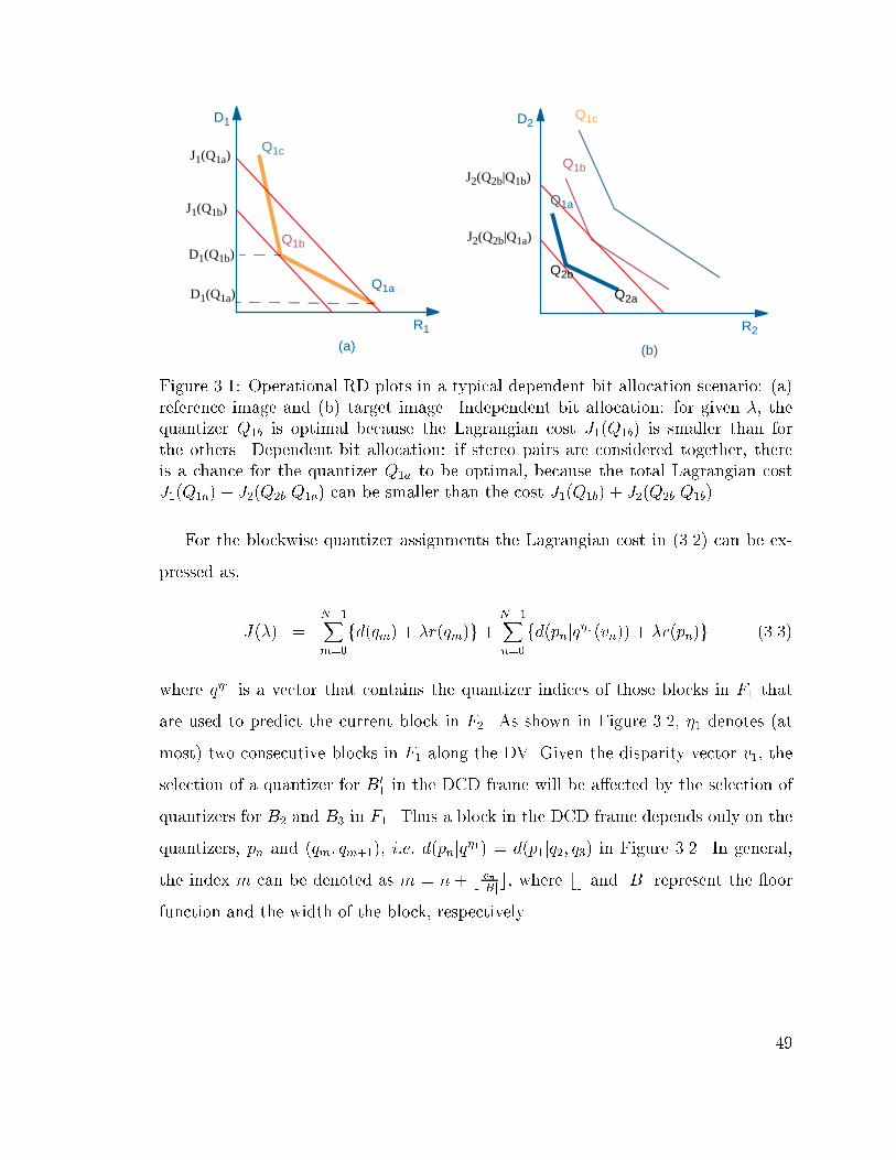
D1
R1
Q1c
Q1a
Q1b
D2
R2
Q1b
Q1a
Q1c
(a) (b)
Q2a
Q2b
J1(Q1b)
J1(Q1a)
J2(Q2b|Q1a)
J2(Q2b|Q1b)
D1(Q1b)
D1(Q1a)
Figure 3.1: Operational RD plots in a typical dependent bit allocation scenario: (a)
reference image and (b) target image. Independent bit allocation: for given �, the
quantizer Q1b is optimal because the Lagrangian cost J1(Q1b) is smaller than for
the others. Dependent bit allocation: if stereo pairs are considered together, there
is a chance for the quantizer Q1a to be optimal, because the total Lagrangian cost
J1(Q1a) + J2(Q2bjQ1a) can be smaller than the cost J1(Q1b) + J2(Q2bjQ1b).
For the blockwise quantizer assignments the Lagrangian cost in (3.2) can be ex-
pressed as,
J(�) =N�1X
m=0
fd(qm) + �r(qm)g+N�1X
n=0
fd(pnjq�1(vn)) + �r(pn)g (3.3)
where q�1 is a vector that contains the quantizer indices of those blocks in F1 that
are used to predict the current block in F2. As shown in Figure 3.2, �1 denotes (at
most) two consecutive blocks in F1 along the DV. Given the disparity vector v1, the
selection of a quantizer for B01 in the DCD frame will be a�ected by the selection of
quantizers for B2 and B3 in F1. Thus a block in the DCD frame depends only on the
quantizers, pn and (qm; qm+1), i:e: d(pnjq�1) = d(p1jq2; q3) in Figure 3.2. In general,
the index m can be denoted as m = n + b vnjBjc, where bc and jBj represent the oor
function and the width of the block, respectively.
49
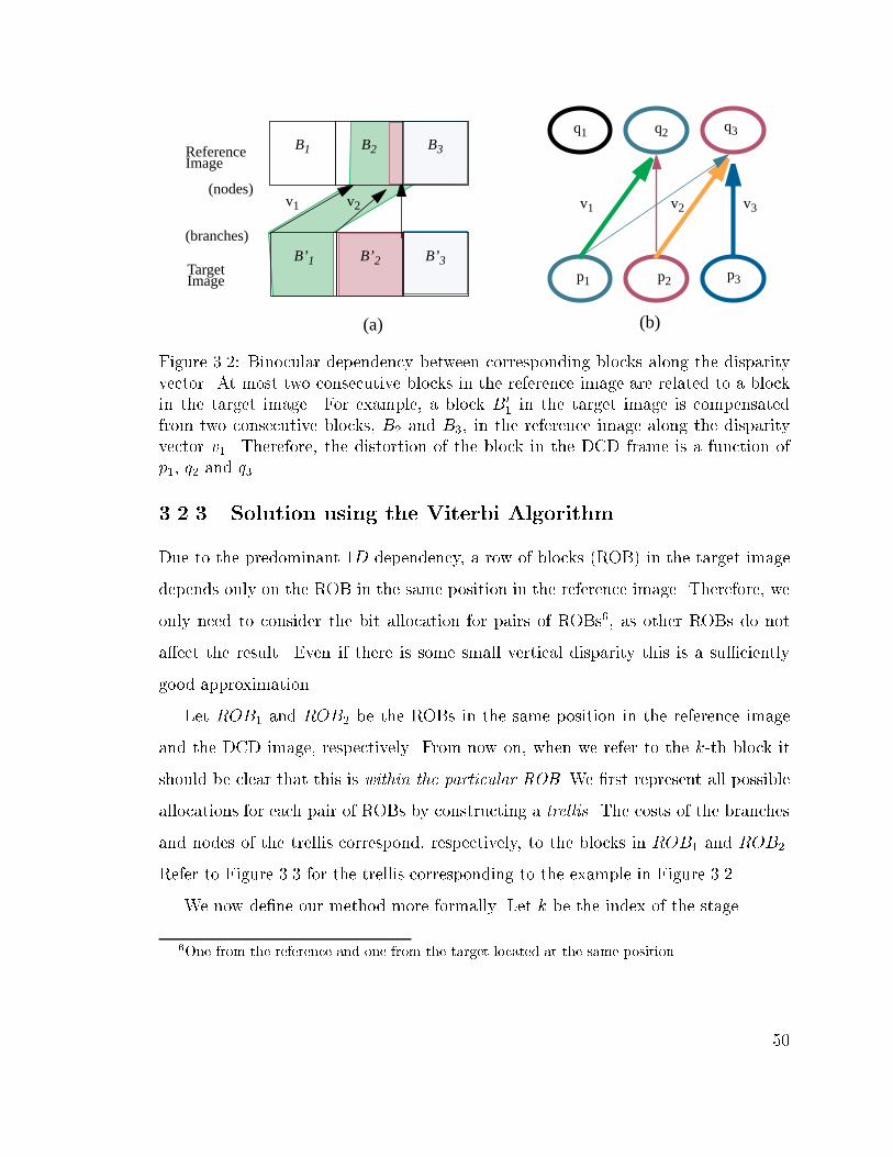
B2B1
p2p1 p3
v1 v2 v3
(b)
q2q1 q3
Reference
TargetB’1 B’2
v1 v2(nodes)
(branches)B’3
Image
Image
(a)
B3
Figure 3.2: Binocular dependency between corresponding blocks along the disparity
vector. At most two consecutive blocks in the reference image are related to a block
in the target image. For example, a block B01 in the target image is compensated
from two consecutive blocks, B2 and B3, in the reference image along the disparity
vector v1. Therefore, the distortion of the block in the DCD frame is a function of
p1, q2 and q3.
3.2.3 Solution using the Viterbi Algorithm
Due to the predominant 1D dependency, a row of blocks (ROB) in the target image
depends only on the ROB in the same position in the reference image. Therefore, we
only need to consider the bit allocation for pairs of ROBs6, as other ROBs do not
a�ect the result. Even if there is some small vertical disparity this is a su�ciently
good approximation.
Let ROB1 and ROB2 be the ROBs in the same position in the reference image
and the DCD image, respectively. From now on, when we refer to the k-th block it
should be clear that this is within the particular ROB. We �rst represent all possible
allocations for each pair of ROBs by constructing a trellis. The costs of the branches
and nodes of the trellis correspond, respectively, to the blocks in ROB1 and ROB2.
Refer to Figure 3.3 for the trellis corresponding to the example in Figure 3.2.
We now de�ne our method more formally. Let k be the index of the stage.
6One from the reference and one from the target located at the same position.
50
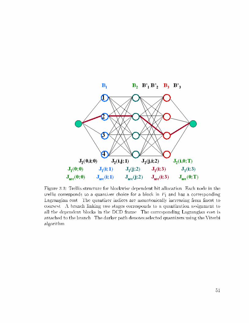
Figure 3.3: Trellis structure for blockwise dependent bit allocation. Each node in the
trellis corresponds to a quantizer choice for a block in F1 and has a corresponding
Lagrangian cost. The quantizer indices are monotonically increasing from �nest to
coarsest. A branch linking two stages corresponds to a quantization assignment to
all the dependent blocks in the DCD frame. The corresponding Lagrangian cost is
attached to the branch. The darker path denotes selected quantizers using the Viterbi
algorithm.
51

Stage: The k-th stage in the trellis corresponds to the k-th block in ROB1. Therefore,
the number of stages, K, is equal to the number of blocks in ROB1.
Node: Each node in the k-th stage corresponds to a possible quantizer choice for the
k-th block of ROB1. The choices are ordered from top to bottom in order of
�nest to coarsest. Therefore, the number of state nodes per stage is L = jqj,
i:e: the number of available quantizers for the reference image. Each node has
a corresponding Lagrangian cost, J1(i; k) in (3.4), which depends only on the
rate and the distortion of the k-th block of ROB1 when quantizer i is used.
J1(i; k) = d(qik) + �r(qik) (3.4)
Branch: A branch, joining nodes qik and qjk+1, corresponds to the optimal vector of quan-
tizers, pijn , for the (possibly more than one) blocks in ROB2 which depend on
blocks k and k + 1 in ROB1. Each branch has a total Lagrangian cost
J2(i; j; k) =X
n2�2(k;k+1)
fd(pijn jqik; q
jk+1) + �r(pijn jq
ik; q
jk+1)g (3.5)
which adds up the Lagrangian costs corresponding to each of the blocks n. Note
that more than one block in ROB2 can be assigned to a given branch (this will
depend on the size of the disparity search region). For example, in Figure 3.2
two blocks in ROB2 are assigned to a branch, i:e: B0
1 and B0
2 both depend on B2
and B3 and thus the two Lagrangian costs corresponding to B0
1 and B0
2 would
be added to each branch linking stages 2 and 3 in the trellis.
Path: A path is a concatenation of branches from the �rst stage to the �nal stage
in the trellis. Each path corresponds to a set of quantization choices for both
ROB1 (nodes) and ROB2 (branches). The cost of a path is the accumulated
cost of branches and nodes along the path.
52

Trellis: The trellis is made of all possible paths linking the nodes in the �rst stage and
the nodes in the last stage, i:e: all possible concatenated choices of quantizers
for a given pair of ROBs in the stereo pair.
Once the trellis has been constructed, the optimal blockwise dependent quantiza-
tion problem is equivalent to �nding the smallest cost path from a node in the �rst
stage to a terminal node in the last stage of the trellis. For a �xed �, by applying
the VA [95], we can obtain the best possible quantizer selection that minimizes the
Lagrangian cost de�ned in (3.3). To �nd the optimal bit allocation for a given bit bud-
get, we may need to iteratively change � until we �nd �� such that R(��)�Rbudget � �,
for � � 0. The desired �� can be selected using a fast bisection search algorithm, as
in the previous chapter [82]. For a �xed � the procedure is as follows,
Step 0: (Initialization:) Add an initial node B0 and a �nal node BT where T = K + 1,
where K denotes the number of stages. Set k = 0 and Jacc(0; 0) = 0.
Step 1: At stage k, branches are added to the end of each node i (of all surviving paths)
and Lagrangian costs, J1 and J2, are assigned to the node and the branch,
respectively.
Step 2: At a stage (k + 1), for each node j, an accumulated transition cost from node
i, Jtr(i; j; k), is calculated by summing the accumulated cost, Jacc(i; k), and the
transition cost, J2(i; j; k). Of all arriving branches (at most L), the one with
the lowest accumulated transition cost is chosen. The resulting cost is assigned
to the accumulated cost, Jacc(j; k + 1) and the remaining branches are pruned.
Jtr(i; j; k) = Jacc(i; k) + J2(i; j; k)
Jacc(j; k + 1) = minfJtr(i; j; k)gL�1i=0
Jacc(j; k + 1) = Jacc(j; k + 1) + J1(j; k + 1) (3.6)
Step 3: If k < K, then k = k + 1, go to step 1 and repeat.
53

Step 4: The path with minimum total cost across all paths can be found by backtracking
the surviving path.
In the proposed framework, the quantization choices for the k-th block in the
reference image and the corresponding blocks in the DCD frame do not a�ect the
choices for the future blocks. Thus, based on the Bellman's optimality principle, the
VA provides a globally optimal solution because suboptimal paths at a given node
cannot be optimal overall and can thus be pruned. Similarly, overall optimality within
the stereo pair can be achieved by assigning the same � to every pair of ROBs since
each pair of ROBs is independent [80, 82].
3.2.4 Fast Algorithm Using Monotonicity
We now propose a fast algorithm based on the monotonicity property, i:e: the obser-
vation that �ner quantization of F1 tends to allow more e�cient coding, in the RD
sense, for the DCD frame [80]. For example, J(pjq�) � J(pjq), for q� � q, where q�
is �ner than q. If � = 0, d(pjq�) � d(pjq), for q� � q. To take advantage of this,
we �rst consider a \ROB1-only optimization" and then only calculate RD values for
the selected nodes and branches. Figure 3.4 shows an example of the reduced trellis
obtained from the trellis of Figure 3.3.
The proposed fast search algorithm is as follows.
Step 0: First, we select a pair of Lagrange multipliers, �'s, e:g:, (�1; �2). For example,
we can choose (0; �2) so that we do not eliminate the �nest quantizer for ROB1
(which tends to be good, given monotonicity).
Step 1: Then, for each �, we set to zero the branch costs and then select, at each stage,
the node, which minimizes D+ �R. Each � will provide an optimal path (a set
of nodes) in the trellis. We then restrict ourselves to only consider those paths
that lie in between the paths selected using �1 and �2.
54

Figure 3.4: A heuristic fast search. The trellis in Figure 3.3 can be restricted using the
proposed fast search algorithm. The search space is reduced to the (circled) nodes,
selected by a blockwise optimization using two �'s for the reference image only. If
we choose the two �'s as (0; �2), then we keep the �nest quantizer for ROB1. Then,
we only need to calculate RD values of the blocks in ROB2 for the remaining (solid
lined) branches.
55

Step 2: Finally, we use the algorithm outlined above except that we apply the VA on
the pruned trellis so that only a subset of the branches representing blocks in
ROB2 need to be grown.
The proposed fast scheme reduces the computational complexity signi�cantly. The
most signi�cant contribution to the complexity of the VA comes from having to
compute the RD values in order to assign the node and branch costs. For example, if
a block in ROB2 depends on two blocks in ROB1, each combination of quantization
choices for these blocks gives rise to a di�erent residue. Thus, we would need to
compute the residues L � L times and to quantize them L times, where L is the
number of quantizers. In other words, the required total number of RD values per
trellis is in O(L3K), because the total number of nodes and branches per trellis are
L � K and L2 � K, respectively. Let the number of remaining nodes per stage in
the pruned trellis be ~L. In our proposed fast scheme, we need only those RD values
corresponding to the remaining nodes and branches in the trellis. Thus, the required
total number of RD values for the pruned trellis is in O(K ~L2L). Based on the above,
if ~L is small, our pruning will result in much reduced complexity and, with good
choices of (�1; �2), will not a�ect much the �nal quality.
3.3 Experimental Results
In our experiments we use two stereo pairs, one synthesized and the other natural.
The test images are shown in Figure B.2 and B.1, and resulting DV �elds are shown
in Figure 3.57. The target image is segmented into blocks of size 8�8 pixels and then
disparity estimation is performed using �xed size block matching. The search window
sizes are (0; 15) and (�2; 15) for the synthesized and the natural pairs, respectively.
7The test images are also available in
http://escalus.usc.edu/~wwoo/Stereo.
The original images where obtained from
Room: http://www-dbv.cs.uni-bonn.de/~ft/stereo.html and
Fruit: http://www.ius.cs.cmu.edu/idb/html/stereo/index.html
56

For this particular selection of the block and search window sizes, two consecutive
blocks in F1 will a�ect at most two consecutive blocks in F2, as shown in Figure 3.3.
Note that our algorithm can accommodate arbitrary search regions.
(a) (b)
Figure 3.5: Test images and DE results with 8� 8 block. The DV �eld with FSBM
for (a) Room (b) Fruit.
The resulting DV �eld is losslessly encoded using DPCM with a causal median
predictor to exploit the spatial redundancy among neighboring DV s. The reference
image and the DCD frame are encoded using a JPEG-like coder, with the only mod-
i�cation to the baseline JPEG [96] being that we allow each block to have a di�erent
quantization scale (QS). Consequently, the change of QS per block allows the encoder
to assign di�erent levels of quantization coarseness to each block. For each block one
among eight di�erent QS can be chosen from the set QS = f90; 80; � � � ; 20g, where
increasing values indicate �ner quantization. In our calculation of rate, we assume a
constant overhead is used for each block.
In our experiments, we compare the RD performance of the blockwise dependent
quantization scheme with those of: (i) framewise constant quantization and (ii) block-
wise independent optimal allocation. Note that a constant quantization scale is used
for all blocks in each image in (i), while the optimal quantization scale for each block
57
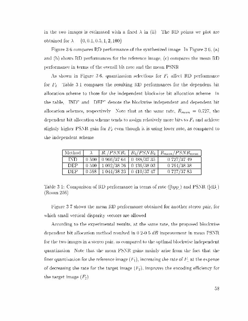
in the two images is estimated with a �xed � in (ii). The RD points we plot are
obtained for � = f0; 0:1; 0:5; 1; 2; 100g.
Figure 3.6 compares RD performance of the synthesized image. In Figure 3.6, (a)
and (b) shows RD performances for the reference image, (c) compares the mean RD
performance in terms of the overall bit rate and the mean PSNR.
As shown in Figure 3.6, quantization selections for F1 a�ect RD performance
for F2. Table 3.1 compares the resulting RD performances for the dependent bit
allocation scheme to those for the independent blockwise bit allocation scheme. In
the table, \IND" and \DEP" denote the blockwise independent and dependent bit
allocation schemes, respectively. Note that at the same rate, Rmean = 0:727, the
dependent bit allocation scheme tends to assign relatively more bits to F1 and achieve
slightly higher PSNR gain for F2 even though it is using lower rate, as compared to
the independent scheme.
Method � R1/PSNR1 R2/PSNR2 Rmean/PSNRmean
IND 0.500 0.966/37.64 0.488/37.35 0.727/37.49
DEP 0.500 1.092/38.76 0.436/38.03 0.764/38.38
DEP 0.588 1.044/38.23 0.410/37.47 0.727/37.83
Table 3.1: Comparison of RD performance in terms of rate ([bpp]) and PSNR ([dB])
(Room.256).
Figure 3.7 shows the mean RD performance obtained for another stereo pair, for
which small vertical disparity vectors are allowed.
According to the experimental results, at the same rate, the proposed blockwise
dependent bit allocation method resulted in 0.2-0.5 dB improvement in mean PSNR
for the two images in a stereo pair, as compared to the optimal blockwise independent
quantization. Note that the mean PSNR gains mainly arise from the fact that the
�ner quantization for the reference image (F1), increasing the rate of F1 at the expense
of decreasing the rate for the target image (F2), improves the encoding e�ciency for
the target image (F2).
58

0.6 0.8 1 1.2 1.4 1.6
32
34
36
38
40
42
44
−x−:Blockwise Ind. Q1
−o−: Blockwise Dep. Q1
−+−:Framewise Q1
R[bpp]
PS
NR
[dB
]
(a)
0.3 0.4 0.5 0.6 0.7 0.8 0.9 1
32
34
36
38
40
42
−o−:Blockwise Dep. Q2
−x−: Blockwise Ind. Q2
−+−: Framewise Q2
R[bpp]
PS
NR
(b)
0.5 0.6 0.7 0.8 0.9 1 1.1 1.2 1.3
32
34
36
38
40
42
−o−: Blockwise Dep. Q−x−: Blockwise Ind. Q−+−: Framewise Q
R[bpp]
PS
NR
[dB
]
(c)
Figure 3.6: RD performance comparison (Image: room.256, Block size=8� 8, SW =
16, jQj = 8, QS = f90; 80; � � � ; 20g and � = f0; 0:1; 0:5; 1; 2; 100g). The '+'-mark
denotes the DC with framewise quantization. The 'x'-mark and 'o'-mark correspond
to the DC with blockwise independent and dependent quantizations, respectively.
Each point is generated with one di�erent �. (a) The RD performance for the reference
image is similar for both types of blockwise allocation. (b) A better RD performance
for the target image can be achieved using the dependent bit allocation approach. (c)
The overall performance also improves when taking dependencies into account.
59
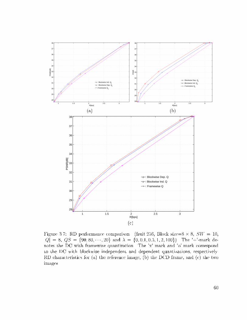
1 1.5 2 2.5 3
28
29
30
31
32
33
34
35
36
37
38
−x−: Blockwise Ind. Q1
−o−: Blockwise Dep. Q1
−*−:Framewise Q1
R[bps]
PS
NR
[dB
]
(a)
1 1.5 2 2.5 328
29
30
31
32
33
34
35
36
37
38
−o−: Blockwise Dep. Q2
−x−: Blockwise Ind. Q2
−+−: Framewise Q2
R[bps]
PS
NR
(b)
1 1.5 2 2.5 3
28
29
30
31
32
33
34
35
36
37
38
−o−: Blockwise Dep. Q
−x−: Blockwise Ind. Q
−+−: Framewise Q
R[bps]
PS
NR
[dB
]
(c)
Figure 3.7: RD performance comparison. (fruit.256, Block size=8 � 8, SW = 10,
jQj = 8, QS = f90; 80; � � � ; 20g and � = f0; 0:1; 0:5; 1; 2; 100g). The '+'-mark de-
notes the DC with framewise quantization. The 'x'-mark and 'o'-mark correspond
to the DC with blockwise independent and dependent quantizations, respectively.
RD characteristics for (a) the reference image, (b) the DCD frame, and (c) the two
images.
60

Figure 3.8 shows mean ORD curves for the reference image (points marked with
x) and the dependent DCD frame (points marked with o), respectively. As shown, the
monotonicity property is satis�ed for the blockwise quantization, i:e: J(QS2jQS1) �
J(QS2jQS�
1), for QS1 � QS�
2 . Thus if the quality of the reference frame improves,
so does the DCD, for the same quantization scale QS2, i:e: if � = 0, d(QS2jQS1) �
d(QS2jQS�
1), for QS2 � QS�
2 [80]. Thus, the �ner quantization (QS1 = 90) leads to
more e�cient coding for the DCD frame in the RD sense so that the corresponding
mean ORD curve is closer to the origin. In addition, the plot shows that, in both
cases, the distortion, d(QS2jQS1), increases monotonically as the quantization scales
changes from �nest to coarsest, i:e: from 90 to 30.
0.2 0.4 0.6 0.8 1 1.2 1.4 1.6 1.80
5
10
15
20
25
30
35
40
R[bps]
MS
E
−x−: reference image
−o−: DCD frame
(QS2|QS
1=90)
(QS2|QS
1=30)
Figure 3.8: Mean ORD plots for the block in the reference image and the DCD
frame. (room.256, QS = f90; 70; 50; 30g) QS2 is changed for the DCD frame with
a given QS1. As shown, the monotonicity property is satis�ed, i:e: J(QS2jQS1) �J(QS2jQS
�
1), for QS1 � QS�
1 . In particular, if � = 0, d(QS2jQS1) � d(QS2jQS�
1), for
QS1 � QS�
1 .
Figure 3.9 shows the RD performance of the proposed fast algorithm. To keep
the �nest quantizers for the reference we set �1 to be zero and thus the selected �'s
61

are f�1; �2g = f0; 0:5g, in our experiments. As explained in the previous section,
we restrict the search space to the nodes in between two paths selected by the two
�'s. Finally, the set of dependent quantization assignments is determined using the
pruned trellis. In our example, only 61% of original nodes and 37.5% of branches
remain in the pruned trellis, which results in signi�cant savings in the computation
of RD values. The resulting number of computation (and thus comparison) in the
pruned trellis is about 37.5% of the original. The overall RD performance remains
practically unchanged in this case, as compared to the original algorithm. Note
however that we need to make a good choice for the � range, based on the expected
quality level for the overall image. Thus, in the example, we show good performance
at high rates whereas the low rate points cannot be achieved since the corresponding
nodes have already been pruned out.
3.4 Discussion
We have proposed an optimal dependent bit allocation scheme for stereo image coding.
We have concentrated on quantization issues and assumed that the disparity estima-
tion was performed open-loop. The proposed dynamic programming algorithm leads
to an e�cient bit allocation between the reference image and the DCD frame. Accord-
ing to our experimental results, the proposed scheme provides signi�cant PSNR gains,
e:g: about 1-2 dB compared to DC with the framewise bit allocations and 0.2-0.5 dB
compared to DC with the blockwise independent bit allocation. In addition, we have
shown a method to reduce the computational complexity and the encoding delay of
the VA by exploiting the monotonicity property. Adopting reasonable RD models
can further reduce the computational complexity of the proposed scheme [91]. This
framework has been developed for a JPEG-like codec but it can be directly extended
to an MPEG-like codec for stereo images, without the loss of generality.
Additional research is required to achieve a more complete allocation algorithm
including the disparity estimation. Further study of our algorithm may lead to a
62

0.6 0.8 1 1.2 1.4 1.6
32
34
36
38
40
42
44
−x−:Blockwise Ind. Q1
−+−: Fast Blockwise Dep. Q1
−o−: Blockwise Dep. Q1
−*−:Framewiae Q1
R[bpp]
PS
NR
[dB
]
(a)
0.3 0.4 0.5 0.6 0.7 0.8 0.9 1
32
34
36
38
40
42
−o−: Blockwise Dep. Q1
−+−: Fast Blockwise Dep. Q1
−x−: Blockwise Ind. Q1
R[bpp]
PS
NR
[dB
]
(b)
0.5 0.6 0.7 0.8 0.9 1 1.1 1.2 1.3
32
34
36
38
40
42
−o−: Dep. Blockwise Q−*−: Fast Dep. Blockwise Q−x−: Ind. Blockwise Q−+−: Framewise Q
R[bpp]
PS
NR
[dB
]
(c)
Figure 3.9: RD performance comparison of the fast algorithm. (room.256, Block
size= 8 � 8, SW = 10, jQj = 8, QS = f90; 80; � � � ; 20g, �1 = [0; 0:5], and � =
f0; 0:1; 0:5; 1; 2; 100g). The '*'-mark denotes the proposed fast algorithm, which only
uses 61% of the original nodes (the resulting computation corresponds to about 22.7%
of the original). The '+'-mark denotes the DC with framewise quantization. The 'x'-
mark and 'o'-mark correspond to the DC with blockwise independent and dependent
quantizations, respectively. RD characteristics for (a) the reference image, (b) the
DCD frame, and (c) the two images combined.
63

better understanding of the similar issues in blockwise dependent allocation for video
coding, where an optimal solution cannot be achieved due to the 2D nature of the
dependencies. Finally, the extension to stereo video coding [11,44,97], in which both
temporal and binocular dependencies have to be taken into account, is another area
of future work.
64

Chapter 4
Modi�ed Overlapped Block Disparity
Compensation
In this chapter, we propose a modi�ed overlapped block matching (OBM) scheme
for stereo image coding. The OBM scheme has been introduced in video coding, as
a promising way to reduce blocking artifacts by using multiple vectors for a block,
while maintaining the advantages of the �xed size block matching framework. Even
though it overcomes some drawbacks of block matching schemes, OBM has its own
limitations. For example, estimating an optimal displacement vector �eld within the
OBM framework may require an iterative search procedure. In addition, OBM does
not always guarantee a consistent DV �eld, even after several iterations, because
the estimation considers only the magnitude of the prediction error as a measure.
Therefore, we propose a modi�ed OBM scheme for stereo image coding, which allows
both consistent disparity estimation and e�cient disparity compensation, without
the need for an iterative procedure. The computational burden resulting from the
iterations is reduced by decoupling the encoding into estimation and compensation.
Consistent disparity estimation is performed by using a causal MRF model and a
half-pixel search, while maintaining (or reducing) the energy level of the disparity
compensated di�erence frame. The compensation e�ciency is improved by both
applying OBM and interpolating the reference image in half pixel accuracy.
65

4.1 Introduction
An e�cient disparity estimation/compensation (DE/DC) has been a main focus
of the research on stereo image/video coding since the pioneering work by Lukacs
[12,13,41,43,53,86]. However, the various proposed schemes only relieve those prob-
lems in part. For example, DE with a Markov random �eld (MRF) model can over-
come the inconsistency by taking advantage of disparity information of neighboring
blocks [27, 86, 98]. Subspace projection is another way of estimating a smooth DV
�eld [41]. However, both schemes have limitations in reducing the energy level of
the DCD frame. The energy level of the DCD frame can be reduced using non-
integer (half or quarter) pixel-based search but that increases the rate of the DV
�eld. Blocking artifacts also can be reduced by adopting various other methods
such as post-processing, segmentation-based estimation/compensation, etc. How-
ever, many post-processing algorithms degrade the quality of the whole image as well
as the block boundaries. Also, the cost to pay for the segmentation is the increase in
overhead to describe the structure of the segmentation [50, 53, 57].
Another promising way to improve encoding e�ciency for stereo images is adopt-
ing overlapped block motion compensation (OBMC), which has been used for video
coding [99{102]. In general, OBMC reduces blocking artifacts by linearly combining
multiple blocks provided by the vectors of a block and its neighbors. For practical im-
plementations, non-iterative OBMC schemes have been proposed. For example, block
matching (BM) [99] or windowed BM [103] is �rst applied for the motion estimation
(ME), without considering the e�ects of neighboring blocks, and then OBMC is per-
formed only for motion compensation (MC). However, these schemes do not always
provide an optimal motion vector (MV) �eld for OBMC. Even the MV �eld itself
may not be optimal because the estimation only depends on the prediction error, i:e:
mean square error (MSE) or mean absolute error (MAE) of the block. Meanwhile,
an optimal MV �eld estimation for OBMC requires complicated iterative schemes to
resolve the noncausal spatial interaction among MVs of neighboring blocks.
66

In conventional approaches, to reduce complexity resulting from the non-causality
problem in ME, a \two-step procedure" is usually adopted, i:e: an initial MV �eld
is estimated using FSBM and then the DV �eld is re�ned to improve the encoding
performance. This process repeats until the DV �eld converges to an optimal state.
However, this iterative process makes optimal OBMC di�cult in real-time applica-
tions [100]. Therefore, at the cost of slightly reduced performance, modi�ed OBMC
schemes such as raster scan OBMC [104] or checkerboard scan OBMC [105,106], have
been proposed to reduce computational complexity. Note however that those schemes
do not always guarantee a smooth displacement (disparity or motion) vector �eld. In
both cases, due to the inconsistency in motion estimation, the overhead may be high
in cases where the displacement �eld is di�erentially encoded using variable-length
codes.
Another weakness of OBMC stems from the �xed shape of the window. Note
that spreading compensation errors tends to reduce blocking artifacts, but it might
degrade compensation e�ciency, particularly for those blocks that can be compen-
sated e�ectively without OBMC. Orchard et al. showed that the optimal shape of the
OBMC window could be determined with the knowledge of the correlation matrix of
the image [100]. However, the required computational complexity is extremely high
for the adaptive window to be implemented in real-time applications.
Therefore, in this chapter, we propose an e�ective but non-iterative OBM scheme
for stereo image coding. In the proposed overlapped block disparity compensation
(OBDC) scheme, the computational complexity resulting from the iterative DE has
been reduced by decoupling the encoding procedure into two steps, i:e: �rst disparity
estimation and then disparity compensation. Note however that non-iterative schemes
may not provide an optimal DV �eld for OBDC in general. Therefore, we propose an
alternative DE/DC strategy to overcome the non-optimality problem. First, the DE
with a modi�ed MRF model and half pixel search results in a smooth DV �eld without
excessively increasing the energy level of the prediction error and thus tends to reduce
67
bit rate for the DV �eld. Then, given a smooth DV �eld, the selective OBDC in half
pixel accuracy reduces blocking artifacts and energy level of the DCD frame. Note
that the selective OBDC adaptively changes the shape of the OBM window to prevent
the oversmoothing problem and thus lowers the computational complexity as well as
the energy level of the DCD frame.
The main novelty of this research is that we introduce an OBDC scheme for stereo
image coding for the �rst time. In the proposed OBDC, the overall encoding per-
formance for the target image is achieved by estimating a smooth DV �eld, while
reducing the energy level of the DCD frame, at a fraction of the computation that
would be required by an OBDC based on conventional OBMC. To verify the e�ective-
ness, we compare the RD performance of the proposed OBDC scheme with various
FSBM-based DE/DC schemes such as (i) simple FSBM, (ii) FSBM with MRF model
and (iii) OBDC based on OBMC. According to our experimental results, the proposed
scheme achieves about 0.5-1 dB gain in terms of PSNR as well as better perceptual
quality, compared to OBDC. Note that the resulting smooth DV �eld also helps gen-
erate intermediate-views with lower visual artifacts in the decoder. The proposed
OBDC scheme can also be applicable to video coding without the loss of generality.
This chapter is organized as follows. In Section 4.2, we describe the proposed
two-step hybrid scheme, the modi�ed OBM with MRF model and half-pixel search.
In Section 4.3, we provide some experimental results to compare the e�ectiveness of
the proposed scheme. Conclusions are summarized in Section 4.4.
4.2 Modi�ed Overlapped Block Matching
4.2.1 Notation and De�nition
We de�ne the (i; j)-th overlapping block in the target image as s2ij and thus each target
block is estimated/compensated as a windowed-sum of a block and its neighboring
blocks along the corresponding DVs. In conventional FSBM, s2ij equals f2ij and thus
68

each target block is estimated from only one block in the reference image along the
disparity vector vij.
In general, the overlapped window W is designed to decay toward the boundaries
on the assumption that blockwise estimation error increases as a pixel moves away
from the block center and the increase is symmetric with respect to the block center
[107]. Another property of the window is that the windowed-sum over the image
is identical to the original image, i:e: F =P
ij W � sij. Typical selections for the
overlapped window are the sinusoidal and the bilinear windows1. An optimal shape for
the overlapped window can also be considered but the resulting improvement is not a
signi�cant one, given the proportional increase in the computational complexity [100].
In our experiments, therefore, we adopt the bilinear window as shown in Figure 4.1
(a). For a 2B � 2B window, window components corresponding to each region of a
block are shown in Figure 4.1 (b)-(e).
The selected separable bilinear window W is de�ned as follows,
W (m;n) = Wm �Wn
Wm = Wn =
8><>:
m+0:5B
; 0 � m < B
W2B�m�1; B � m < 2B(4.1)
whereWm andWn denote the separable vertical and horizontal windows, respectively.
4.2.2 Disparity Estimation Using Overlapped Windows
Figure 4.2 shows the DE using overlapped window and a smoothness constraint. In
general, the DV �eld obtained by the overlapped window is not likely to be consistent
because the MSE/MAE-based prediction is sensitive to various noise e�ects such as
intensity variation. Note that the two images in a pair may have slightly di�erent
1Note that FSBM can be considered as a OBM with a rectangular function.
69

0
5
10
15
0
5
10
15
0.1
0.2
0.3
0.4
0.5
0.6
0.7
0.8
(a)
01
23
45
67
01
23
45
670
0.2
0.4
0.6
0.8
1
(b)
01
23
45
67
01
23
45
670
0.2
0.4
0.6
0.8
1
(c)
01
23
45
67
01
23
45
670
0.2
0.4
0.6
0.8
1
(d)
01
23
45
67
01
23
45
670
0.2
0.4
0.6
0.8
1
(e)
Figure 4.1: Bilinear window function for the overlapped block matching and its com-
bined weighting matrices. (a) Bilinear OBM window (16 � 16) (b) Main (f̂ 2ij�vij
)
(c) Horizontal (f̂ 2ij(N)�vi�1j
; f̂2ij(S)�vi+1j
) (d) Vertical (f̂ 2ij(W )�vij�1
); f̂ 2ij(E)�vij+1
) (e) Cor-
ner (f̂ 2ij(NW )�vi�1j�1
; f̂2ij(NE)�vi�1j+1
; f̂2ij(SW )�vi+1j�1
; f̂2ij(SE)�vi+1j+1
). The capital letters
(N,W,S,E) denote locations of quadrants of a block, i:e: north, west, south, and east,
respectively.
intensity levels due to the camera noise and lighting condition. In addition, the lack
of texture and/or repetitive texture may disturb consistent estimation.
Therefore, we introduce an MRF model to estimate a smooth DV �eld by con-
sidering the DV �eld and the estimation error together. In general, conventional
MRF-based schemes have high computational complexity because they require sev-
eral (stochastic) iterations to estimate an optimal (pixelwise) dense DV �eld [84].
Thus, we propose a simpli�ed blockwise DE scheme for stereo image coding, which
estimates a smooth DV �eld without complicated iterations by considering only blocks
in a �rst order causal neighborhood as shown in Figure 4.3. Meanwhile, the same
neighborhood is used for encoding the DV �eld, i:e: the di�erence between vij and the
median of its causal neighborhood is encoded using DPCM. As a result, estimating a
smooth DV �eld contributes to reducing side information, which is especially essential
at low rate coding.
70

Figure 4.2: Disparity estimation based on block matching with an enlarged window.
In the target image, shaded and dashed areas correspond to a block, fij, and an
enlarged block, sij, respectively.
Figure 4.3: A �rst order causal neighborhood. The same neighborhood is used in the
encoding of the DV �eld, i:e: Diff(vij) = vij �median(vWij ; vNij ; v
NEij ).
71
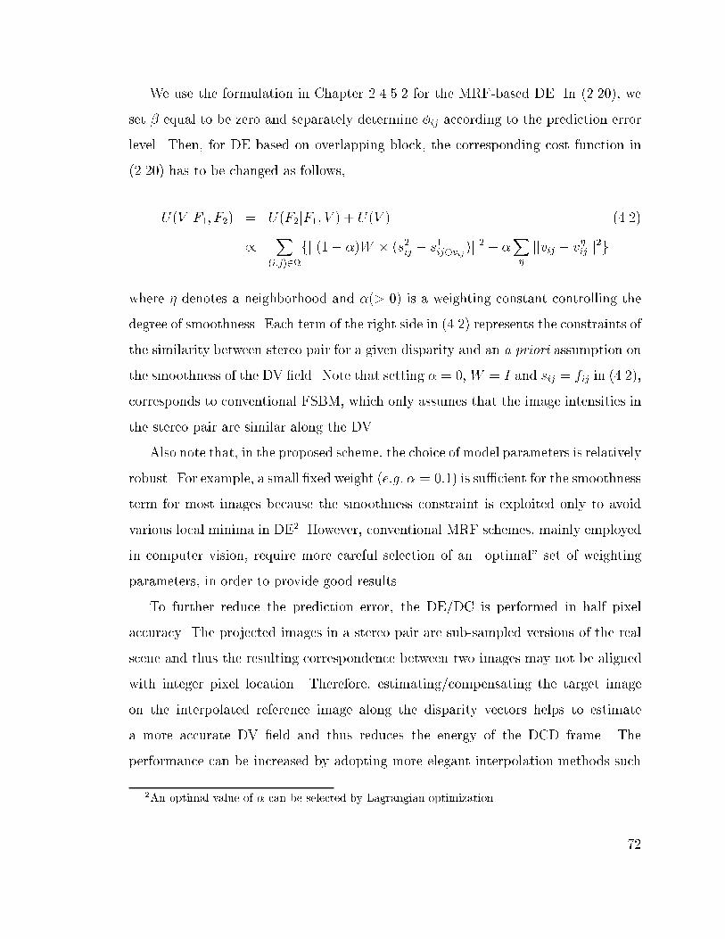
We use the formulation in Chapter 2.4.5.2 for the MRF-based DE. In (2.20), we
set � equal to be zero and separately determine �ij according to the prediction error
level. Then, for DE based on overlapping block, the corresponding cost function in
(2.20) has to be changed as follows,
U(V jF1; F2) = U(F2jF1; V ) + U(V ) (4.2)
/
X
(i;j)2
fjj(1� �)W � (s2ij � s1ij�vij
)jj2 + �
X�
jjvij � v�ijjj
2g
where � denotes a neighborhood and �(> 0) is a weighting constant controlling the
degree of smoothness. Each term of the right side in (4.2) represents the constraints of
the similarity between stereo pair for a given disparity and an a priori assumption on
the smoothness of the DV �eld. Note that setting � = 0,W = I and sij = fij in (4.2),
corresponds to conventional FSBM, which only assumes that the image intensities in
the stereo pair are similar along the DV.
Also note that, in the proposed scheme, the choice of model parameters is relatively
robust. For example, a small �xed weight (e:g: � = 0:1) is su�cient for the smoothness
term for most images because the smoothness constraint is exploited only to avoid
various local minima in DE2. However, conventional MRF schemes, mainly employed
in computer vision, require more careful selection of an \optimal" set of weighting
parameters, in order to provide good results.
To further reduce the prediction error, the DE/DC is performed in half pixel
accuracy. The projected images in a stereo pair are sub-sampled versions of the real
scene and thus the resulting correspondence between two images may not be aligned
with integer pixel location. Therefore, estimating/compensating the target image
on the interpolated reference image along the disparity vectors helps to estimate
a more accurate DV �eld and thus reduces the energy of the DCD frame. The
performance can be increased by adopting more elegant interpolation methods such
2An optimal value of � can be selected by Lagrangian optimization.
72
as an approximated ideal �lter or Wiener �lter [108, 109]. Clearly the higher the
subpixel accuracy (i:e: the larger displacement space), the greater the probability of
�nding a good match. Note however that we cannot choose an arbitrarily small value
because, as the subpixel accuracy increases, both the rate for the resulting DV �eld
and the number of candidate blocks being compared in the search area increase at
the same time. In our experiments, we use bilinear interpolation, as a compromise, to
obtain the half-pixel precision intensity value, as used in most video coding standards.
4.2.3 Encoding with Selective OBDC
In general, OBDC is e�cient only when the energy level of the DCD block is sig-
ni�cantly di�erent with its neighboring blocks or when high frequency components
exist in the DCD block. Thus, during the DE process, a block with higher prediction
error than a threshold is selected as an OBDC candidate. The DCD is calculated
by taking the di�erence between the predicted block and the original block in the
target image, i:e: DCD = f2ij � f̂
2ij. Let �
0 and � denote an initial occlusion and an
occlusion, respectively. Then, OBDC is only considered for the block with �0 = 1.
Note that a block with �0ij = 0 can be compensated e�ectively without OBDC. First,
�0ij = 1, if jDCDj > T�, where T� denotes a threshold value. For each block with
�0ij = 1, if the energy level of the DCD using OBDC is lower as compared to block
DC (BDC), then �ij = 1. Meanwhile, a block having the same DV with its neighbors
is selected �ij = 0, since there is no RD gain by OBDC when the disparity vectors of
the neighboring blocks are the same. Otherwise, i:e if there is no gain from BDC or
OBDC, the original intensity block is encoded instead of the DCD block.
As shown in Figure 4.4, in OBDC, a target block is in uenced by the nine over-
lapped blocks in the reference image along the corresponding disparity vectors. Thus,
the whole compensation is obtained by summing up the window-operated nine blocks.
73
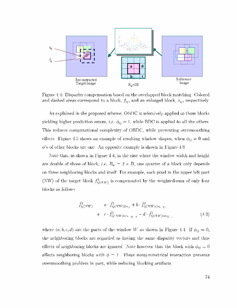
Figure 4.4: Disparity compensation based on the overlapped block matching. Colored
and dashed areas correspond to a block, fij, and an enlarged block, sij, respectively.
As explained in the proposed scheme, OBDC is selectively applied to those blocks
yielding higher prediction errors, i:e: �ij = 1, while BDC is applied to all the others.
This reduces computational complexity of OBDC, while preventing oversmoothing
e�ects. Figure 4.5 shows an example of resulting window shapes, when �ij = 0 and
�'s of other blocks are one. An opposite example is shown in Figure 4.6.
Note that, as shown in Figure 4.4, in the case where the window width and height
are double of those of block, i:e: Bw = 2 � B, one quarter of a block only depends
on three neighboring blocks and itself. For example, each pixel in the upper left part
(NW) of the target block f2ij(NW ) is compensated by the weighted-sum of only four
blocks as follows
f̂2ij(NW ) = a � f̂
2ij(NW )�vij
+ b � f̂2ij(NW )�vi�1j
+ c � f̂2ij(NW )�vi�1j�1
+ d � f̂2ij(NW )�vij�1
(4.3)
where (a; b; c; d) are the parts of the window W as shown in Figure 4.4. If �ij = 0,
the neighboring blocks are regarded as having the same disparity vectors and thus
e�ects of neighboring blocks are ignored. Note however that the block with �ij = 0
a�ects neighboring blocks with � = 1. These nonsymmetrical interaction prevents
oversmoothing problem in part, while reducing blocking artifacts.
74

0
5
10
15
05
1015
0
0.1
0.2
0.3
0.4
0.5
0.6
0.7
0.8
(a)
0
5
10
15
05
1015
0
0.1
0.2
0.3
0.4
0.5
0.6
0.7
0.8
(b)
05
1015
0
5
10
15
0
0.1
0.2
0.3
0.4
0.5
0.6
0.7
0.8
(c)
0
5
10
15
05
1015
0.1
0.2
0.3
0.4
0.5
0.6
0.7
0.8
0.9
1
(d)
Figure 4.5: Adaptive windowing for selective overlapped block disparity compensa-
tion. Given �ij = 0 and �i�1j�1 = �i�1j = �ij�1 = 1, OBM windows are changed
adaptively according to the �'s. OBM windows for (a) si�1j�1 (b) si�1j (c) sij�1 (d)
sij.
0
5
10
15
05
1015
0
0.1
0.2
0.3
0.4
0.5
0.6
0.7
0.8
0.9
1
(a)
0
5
10
15
05
1015
0
0.1
0.2
0.3
0.4
0.5
0.6
0.7
0.8
0.9
1
(b)
0
5
10
15
05
1015
0
0.1
0.2
0.3
0.4
0.5
0.6
0.7
0.8
0.9
1
(c)
0
5
10
15
05
1015
0
0.1
0.2
0.3
0.4
0.5
0.6
0.7
0.8
(d)
Figure 4.6: Adaptive windowing for selective overlapped block disparity compensa-
tion. Given �ij = 1 and �i�1j�1 = �i�1j = �ij�1 = 0, OBM windows are changed
adaptively according to the �'s. OBM windows for (a) si�1j�1 (b) si�1j (c) sij�1 (d)
sij.
75
The encoding procedure based on the proposed selective OBDC is as follows
� Step 0 The reference image is independently encoded using JPEG.
� Step 1 The disparity is estimated using an enlarged bilinear window with
Bw = 2B. The window function W is operated on the disparity-predicted
di�erence, without considering DE errors of neighboring blocks, i:e: eobm;ij =
jjW�fs2ij�s
1ij�vij
gjj. The corresponding DE cost is de�ned by adding a smooth-
ness constraint as shown in (4.2). The estimation is performed in half-pixel
accuracy.
� Step 2 Given a DV, a block is determined as an OBDC candidate, if the
energy level of the di�erence, DCD = f2ij � f̂
2ij, is larger than the threshold. If
jDCDj > T�, �0ij = 1. Otherwise, �0ij = 0.
� Step3 After DE with windowed BM, for each block with �0ij = 1, the DV is
re�ned by considering OBDC. If the resulting DCD has less energy than that of
BDC, the block is selected as OBDC block, i:e: �ij = 1. If there is no gain from
either BDC or OBDC, the block is replaced with the original intensity block.
� Step 4 OBDC is selectively performed for those blocks with �ij = 1 by summing
up all windowed compensation blocks based on (4.3).
� Step 5 The resulting DV �eld and DCD frame are encoded using DPCM and
JPEG, respectively. For DPCM of the DV �eld, its median is selected from the
pre-de�ned causal neighborhood.
At the decoder, the reference image is decoded �rst and then the target image
is reconstructed according to �ij, e:g: by performing OBDC, if �ij = 1 and BDC,
otherwise. The �nal target image is reconstructed by adding information from the
DCD for those blocks that have been predicted.
76

4.3 Experimental Results
In this experiment, the right image is selected as reference image and then a constant
quantization factor (Q1 = 80) is assigned for that reference image. Exhaustive search
is performed within a search range of [0;�15] pixel in half-pixel accuracy. For the
images that do not satisfy the parallax constraints, we search �2 pixels in vertical
direction. In order to test the e�ectiveness of the proposed algorithm, we have simu-
lated its performance for two pairs of stereo images; a synthesized scene, Room, and
a natural scene, Aqua. The image sizes of the pairs are 256 � 256 and 288 � 360,
respectively. The used stereo pairs are as shown in Figures B.2 and B.33.
First, we investigate how the block size a�ects the RD performance. Figure 4.7
compares the resulting DV �elds of the Room image, which are obtained from FSBM
for six di�erent block sizes, from 32 � 32 to 1 � 1. Note that as the block size
is reduced the resulting disparity �eld appears to be noisier, even though those DV
�elds reduce the estimation errors. The smaller block sizes also result in increase of
the rates required to transmit the DV �elds and thus may not be useful in practice.
Figure 4.8 shows the corresponding RD curves with di�erent block sizes. The
performance is measured in terms of the bit rates of the encoded images and peak
signal to noise ratio (PSNR). As expected, DE/DC-based coding provides better
coding performance than two independent coding (JPEG) of each image, because
DE/DC-based coding takes advantage of the binocular redundancy in a stereo pair.
However, obviously, as we reduce the block size(� 2 � 2), the bit rate of the DV
�eld increases while the estimation error is reduced. As a compromise between the
overhead and the energy of the estimation error, we choose a block size of 8 � 8 for
DE in the following experiments.
Figure 4.9 compares the DV �elds of for various disparity estimation methods: (i)
FSBM, (ii) DE with MRF (in [86]), (iii) DE with OBM, (iv) MRF with half-pixel
3The decoded images and the used source codes (based on JPEG coder), are available at
http://escalus.usc.edu/~wwoo/Stereo/
77

(a) (b)
(c) (d)
(e) (f)
Figure 4.7: Disparity vector �eld using a simple FSBM with di�erent size of block
(Room). (a) 32 � 32 (0.003 bps) (b) 16 � 16 (0.012 bps) (c) 8 � 8 (0.046 bps) (d) 4
� 4 (0.169 bps) (e) 2 � 2 (0.725 bps) (f) 1 � 1 (3.151 bps)
78

0.2 0.3 0.4 0.5 0.6 0.7 0.8 0.9 1
28
30
32
34
36
38
[RD: room]
PS
NR
[dB
]
Bit Rate [bits/pixel]
−o−: BM8
−<−: BM16
−v−: BM4
−+−: BM32
−s−: JPEG
−*−: BM2
Figure 4.8: RD plot of FSBM with di�erent block sizes. In the plot, `-s-' denotes a
square-mark line, and `-<-' and `-v-' denote the direction of triangle in the triangle-
mark line. The subscript represents the block size. Note that the RD performance
of the smaller block (e:g: 2� 2) is worse than that of JPEG, because the rate for the
DV �eld is too high.
79

search, (v) OBM with half-pixel search and (vi) the proposed scheme (OBM with
MRF and half-pixel search). As expected, the MRF-based DE estimates a smoother
DV �eld by the tradeo� between the spatial correlation in a stereo pair and the
smoothness in the DV �eld. The proposed hybrid method provides the most smooth
and consistent DV �eld.
Figure 4.10 (a) and (b) compare the corresponding RD plots for the two stereo
pairs, Room and Aqua, respectively. The proposed selective OBDC scheme is com-
pared to FSBM, MRF and OBMC in terms of PSNR and bit rate of the target image.
The results of JPEG without disparity compensation are also provided for reference.
Note that for the natural image pair (Aqua), the RD gain of FSBM is relatively small,
compared to those of Room.
As expected, the proposed selective OBDC in half-pixel accuracy results in an
improved overall encoding performance, i:e: a lower bit rate for the DV �eld and
DCD frame while maintaining a PSNR gain. The modi�ed MRF model-based DE
maintains the energy level of the DCD frame (or slightly increases according to �),
while estimating a consistent DV �eld using smoothness constraint within causal
neighbors. Then, the estimation/compensation in half-pixel accuracy reduces the
energy level of the DCD frame. Note that the smoothness term also reduces the
increase in rate of the DV �eld due to the half-pixel search. Selective OBDC reduces
oversmoothing problem as well as blocking artifacts by summing the neighboring
compensated blocks using the changing OBM window. According to our experimental
results, the proposed modi�ed OBDC scheme obtains a higher PSNR, about 0.5-1 dB,
as well as better perceptual quality, over conventional OBMC schemes. In addition,
selectively applying OBDC reduced the computational complexity over OBMC.
80

(a) (b)
(c) (d)
(e) (f)
Figure 4.9: DV �elds for various disparity estimation methods: (a) FSBM (0.046
bps), (b) DE with MRF (0.032 bps), (c) DE with OBM (0.038 bps), (d) MRF with
half-pixel search (0.042 bps), (e) OBM with half-pixel search (0.065 bps) and (f)
OBD with MRF and half-pixel search (0.060 bps). The combined method provides
the most smooth and consistent DV �eld.
81

0.2 0.3 0.4 0.5 0.6 0.7 0.8
29
30
31
32
33
34
35
36
37
38
39
[RD: room]
PS
NR
[dB
]
Bit Rate [bits/pixel]
−o−: Hybrid
−x−: OBM
−+−: MRF
−*−: FSBM
−s−: JPEG
(a)
0.2 0.3 0.4 0.5 0.6 0.7 0.8 0.923.5
24
24.5
25
25.5
26
26.5
27
27.5
28
[RD: Aqua]
PS
NR
[dB
]
Bit Rate[bits/pixel]
−o−: Hybrid
−x−: OBM
−+−: MRF
−*−: FSBM
−s−: JPEG
(b)
Figure 4.10: The resulting RD plots. (a) Room (b) Aqua. Various DE/DC methods
(block size of 8 � 8, quality factor for the reference image Qf1=80): The proposed
hybrid scheme is compared with JPEG, FSBM, FSBM with MRF, and OBM. In the
plot, `-s-' denotes the square-mark line.82

4.4 Discussion
We presented a novel hybrid DE/DC scheme for stereo image coding. As expected,
MRF-based DE allows estimating a smooth DV �eld. Also, selective OBDC in half-
pixel accuracy results in better compensation by reducing the energy level of the DCD
frame as well as the blocking artifacts. According to our experimental results, the
proposed OBDC scheme provides a higher PSNR as well as better perceptual quality
over other FSBM schemes such as MRF or OBMC, encoded at the same rate. The
results of the proposed selective OBDC schemes also can be applied into video coding
without the loss of generality. It is also worth noting that obtaining a smooth disparity
is useful for multi-view video coding since the robustness against noise can help reduce
the temporal redundancy between two consecutive disparity �elds. However, there
remain several problems to be resolved. The overall encoding performance could be
improved by combining the proposed DE scheme and the dependent bit allocation
scheme proposed in [39, 59].
83

Chapter 5
MRF-based Hierarchical Block Segmentation
In this chapter, we propose a novel quadtree-based disparity estimation/compensation
(DE/DC) algorithm for stereo image coding. Variable size block matching (VSBM)
is a way of overcoming those well-known limitations of �xed size block matching
(FSBM), such as inaccurate disparity estimation and blocking artifacts in the de-
coded target image. However, VSMB may su�er from the inconsistency problem in
disparity estimation especially as the subblock becomes small. In addition, the re-
sulting disparity compensated di�erence frame contains high frequency components
along subblock boundaries as a result of block segmentation. Therefore, we propose
a hybrid quadtree-based DC/DC scheme, where DE with MRF model-based VSBM
allows estimation of a consistent disparity �eld. The combination of RD cost-based
block segmentation and selective overlapped block disparity compensation improves
the encoding e�ciency over conventional VSBM schemes. According to the experi-
mental results, the proposed block segmentation scheme achieves a higher PSNR gain,
while generating a relatively consistent disparity �eld, as compared to conventional
VSBM schemes. The proposed scheme also yields fewer visual artifacts along object
boundaries.
84

5.1 Introduction
As with in the video case, block-based predictive coding has been widely used to en-
code stereo images/video. However, as explained in Chapter 4, inaccurate estimation
is inevitable in �xed size block matching (FSBM). Besides, FSBM may introduce
the annoying blocking artifacts in the decoded target image at a low rate coding,
where only few bits are employed to encode the disparity compensated di�erence
(DCD) frame. Since Lukacs [12] introduced FSBM in stereo image coding, various
block-based DE/DC schemes have been studied to reduce the well-known drawbacks
of FSBM [41, 45, 86, 110]. Nevertheless, conventional FSBM-based approaches only
relieve few of the problems.
An alternative is a hierarchical approach relaxing the uniform-disparity-per-block
assumption [51,53,111,112]. In term of the DCD frame, it is desirable to segment an
image into smaller blocks to reduce the entropy of the DCD frame. However, it may
not be worth computing a dense disparity �eld, if the cost of transmitting or storing
the DV �eld is too high. On the other hand, the number of blocks could not be too few
because larger blocks result in higher estimation errors. As a compromise, variable
size block matching (VSBM) has been introduced in image/video coding. A main
advantage of VSBM is that larger blocks are used in homogeneous areas (background
or inside of object) and smaller blocks are used in object boundary areas. Thus, the
disparity compensation can be performed properly, even if the initial block contains
several objects with di�erent disparity vectors or contains an occlusion area. The
representation of the resulting disparity vector (DV) �eld generally relies on a binary
tree [113] or a quad tree [46, 48, 50, 77, 114].
However, like FSBM, the quadtree-based VSBM has similar limitation in a con-
sistent DV �eld estimation. In general, block segmentation is determined by various
intuitive ad hoc criteria such as threshold, features, local variance of the DCD, local
motion activities and/or rate-distortion (RD) [47,48,111,113,115{119]. However even
if RD-based segmentation approaches are used, the segmentation may not take into
85
account the consistency of the displacement. As a result, DE with smaller blocks
su�ers from the noise e�ects or aperture problem1. Consequently, the neighboring
blocks may have many di�erent vectors, resulting in ine�cient encoding for the DV
�eld, because each vector minimizes only the prediction error of the block. Usually,
smaller blocks such as 2�2 or 1�1 are very sensitive to noise and thus, in conventional
VSBM, 8� 8 (or 4� 4) is considered as the smallest block2. In addition, the segmen-
tation of the block into smaller subblocks may result in the DCD frame containing
high frequency components, within the initial block, along subblock boundaries. As
a result, DCT for those subblocks may not e�cient because the segmented block
requires more bits to encode those high frequency components.
Therefore, we propose a novel quadtree-based disparity estimation/compensation
scheme to overcome those weaknesses of VSBM. The proposed scheme consists of
three components: (i) disparity estimation using an MRF model, (ii) hierarchical
block segmentation by the quadtree pruning based on the simpli�ed RD cost and (iii)
selective overlapped block disparity compensation (OBDC) for the segmented sub-
blocks. The novelty of the proposed VSBM scheme is that the hierarchical disparity
estimation with MRF model allows estimating a consistent DV �eld, i:e: a relatively
smoother DV �eld. Obtaining a smooth DV �eld is bene�cial as it reduces the rate for
the DV �eld itself and segmenting blocks based on the RD cost improves the encod-
ing e�ciency. In addition, the selective OBDC for the segmented subblocks improves
the encoding e�ciency by reducing blocking artifacts within segmented blocks. The
main improvement over the OBDC scheme proposed in Chapter 4 comes from the
fact that we segment the occlusion blocks according to the prede�ned RD cost and
thus we use overlapped windows with di�erent sizes and shapes for those segmented
subblocks. For selective OBDC, no side information is required because a quadtree
1In areas without signi�cant features (or with repetitive features), a smaller block usually su�er
from many local minima within search window during displacement estimation.2Note that in H.26x, for each macroblock block, the segmentation is preset only one time (from
16� 16 to 8� 8), which may not be suitable for object-based coding such as MPEG-4.
86

already contains block segmentation information. Consequently, the proposed scheme
allows more accurate disparity estimation/compensation along the object boundaries
and thus reduces the visual artifacts along the object boundaries while maintaining
encoding e�ciency of the target image.
The proposed VSBM scheme is also of general interest in image analysis or synthe-
sis/generation as well as image coding by producing useful intermediate information
for various applications. For example, in new standards such as MPEG-4, the pro-
posed scheme can help object-based segmentation of the image by combining both the
intensity and the disparity information together. In video coding, the motion informa-
tion has been used to estimate the boundaries of moving objects according to motion
homogeneity, under the assumption that the objects have rigid motion. Thus, the
applications have been restricted to simple video-phone-like sequences [120]. Mean-
while, in stereo images, an image can be segmented into di�erent objects because
not only moving objects but also all objects within the scene have di�erent disparity
vectors.
According to our experimental results, the proposed scheme provides higher RD
performance as well as better perceptual quality, while also being computationally
e�cient. To prove the e�ectiveness, we compare the proposed scheme with a simple
VSBM scheme. According to our experimental results, the proposed scheme results
in an improved peak-signal-to-noise-ratio (PSNR) gain, about 0.5-1.5 dB, as well as
better perceptual quality, as compared to simple VSBM, which segments blocks based
on threshold values.
This chapter is organized as follows. In Section 5.2, we brie y explain the main
components of the proposed scheme, MRF model-based disparity estimation and RD-
based block segmentation. The proposed encoding procedure is described in Section
5.3. In Section 5.4, we provide some experimental results to compare the e�ectiveness
of the proposed scheme. The conclusion is made in Section 5.5.
87

5.2 Variable Size Block Matching
5.2.1 DE with MRF Model for VSBM
In VSBM, each block is successively subdivided into quadrants until no further di-
vision is necessary. The basic idea of VSBM-based coding is that the subblocks are
encoded only when they signi�cantly improve encoding e�ciency over their upper
block. The main advantage of the hierarchical DE with MRF model is that it can
overcome the mismatching problem (inconsistency of the DV �eld) by considering
blocks in upper level as well as neighboring blocks, while maintaining encoding e�-
ciency.
To estimate a smooth DV �eld, we consider the DV �eld as a coupled MRF model
consisting of disparity process and occlusion process. We can similarly formulate DE
problem as we did in Chapter 4 and in [86, 110]. The main di�erence is that we
de�ne a neighborhood in hierarchical layers as shown in Figure 5.1. We �rst derive
an energy equation for hierarchical block matching based on the MRF model, which
allows us to �nd a smooth DV �eld. In order to achieve an e�cient estimation of
the DV �eld, we can impose some useful and realistic constraints on the DV �eld,
such as similar intensity level between the two corresponding images in a stereo pair,
smooth disparity �eld, occlusion �eld, etc. Note that we only segment occlusion block
to improve the overall encoding e�ciency.
For the proposed VSBM, (2.20) has to be changed as follows,
U(V;�jF1; F2) =X
i2N
K�1X
k=0
f(1� �)(1� �lki )jjblk2i � blk�v
lk
1i jj2
(5.1)
+�X
�lk
(1� ��lki )(vlki � v
�lki )
2+ �X
c2Cl
Vc(�lki ; �
�lki )g
where blk denotes the k-th block in the l-th level of the segmentation, where K = 4lfor
the quadtree-based segmentation. Similarly, vlk and �lk denote the disparity vector
and the occlusion status of blk.
88

Figure 5.1: Neighborhood System For VSBM. We use 1storder neighborhood system.
The larger neighborhood, the greater the in uence from its neighborhood.
The �rst term of the right side in (5.1) represents the constraints of the similarity
between two images in a stereo pair for a given disparity and occlusion. Note that the
block containing multiple objects or object boundaries results in erroneous matching.
If the block in F1 fails to be compensated from a block in F2, the block is selected as
an occlusion candidate and then segmented further into subsequent subblocks. Note
that if we ignore the occlusion and the smoothness terms, the above algorithm simply
becomes the conventional block matching.
The second term in (5.1) represents an a priori assumption on the smoothness
of the DV �eld, V , given the occlusion, �, which will be used to tradeo� between
the smoothness and the estimation error. We assume that the real disparity �eld is
smooth except for the object boundaries (due to occlusion) that are related to the
depth discontinuities. Note that generating a smooth disparity �eld not only mitigates
the e�ects of noise, but also increases the encoding e�ciency for the disparity, because
similar disparities in adjacent blocks results in lower entropy. For VSBM, we de�ne
a neighborhood system in a hierarchical structure as shown in Figure 5.1.
The last term in (5.1) denotes an occlusion process. We can impose an a priori
assumption on the occlusion �eld such as connected occlusion. The isolated occlusion
89

is inhibited. In this experiments, we set � to be zero and then decide the initial
candidate by comparing the magnitude of the mean absolute error (MAE) of the
block with a pre-selected threshold. The detailed occlusion block selection procedure
is explained in Chapter 4.
Finally, we selectively apply VSBM and OBDC for those occlusion blocks.
5.2.2 RD-based Hierarchical Block Segmentation
In order to achieve better overall coding performance than the FSBM-based meth-
ods, further segmentation of an occlusion block has to be performed in an e�cient
manner. An optimal hierarchical block segmentation can be searched in the RD-plot
using a Lagrange multiplier (� � 0), by minimizing a cost function according to the
available bit budget, Rbudget, or allowable distortion, Dbudget. In general, RD-based
segmentation can be considered in various aspects. First of all, all the blocks in an
image can be considered simultaneously to achieve a global optimization [39]. Also
the bu�er-constrained optimal block segmentation can be performed for groups of
blocks [81, 121]. In this chapter, we perform the block segmentation for each block
on the assumption that minimizing the cost of each block also minimizes the global
coding cost [48, 82].
Quadtree can be constructed by using top-down or bottom-up approaches. In this
chapter, we adopt a top-down approach, where a hierarchical block segmentation can
be performed using the Lagrangian cost. For blockwise segmentation, the number of
possible trees can be approximated as S �= 24l, where l denotes the depth of a tree.
For example, for l = 4 (from 32 � 32 to 2 � 2), S �= 2256
. Therefore, the optimal
segmentation based on exhaustive search is too computationally expensive. To reduce
the complexity, we adopt a tree-pruning technique.
Let T and P , respectively, be sets of full trees and pruned trees, i:e: T2 = fT2i; 0 �
i < Ng and P2 = fP2i; 0 � i < Ng. In VSBM, an initial block fi is assigned to the
root node of Ti or Pi. In quadtree-based VSBM, an initial block (the usual size
90

is 32 � 32 or 16 � 16) is segmented into a l-level hierarchical structure, where the
block size of a subblock is B � 2�l � B � 2�l. The number of subblocks is K = 4l,
where l denotes the level (or depth) of tree and the maximum level is L = log2B.
The subsequent subblocks are assigned to the children nodes, consisting of leaf and
internal nodes. A leaf node is de�ned as a node without children. Meanwhile, a node
with children is called an internal node. The pruned tree is represented by using a
sequence of bits, where "0" and "1" are used to indicate an internal or a leaf node,
respectively.
In general, for a block segmentation considering the rate and distortion, the cost
of the pruned tree P �is less than that of the full tree T , i:e: C(P �
) � C(T ), where
R(P �) � R(T ) and D(P �
) � D(T ). To achieve an e�cient segmentation, the decision
of block segmentation can be made by comparing the Lagrangian costs of the parent
and children nodes. We �rst de�ne a blockwise Lagrangian cost cl for the hierarchical
segmentation as follows,
cli =X
k2cli
fdlki + �rlki g (5.2)
where dlk and rlk denote the distortion and the rate of the block, blki , respectively.
Lagrange multiplier (� � 0) controls the weight between d and r. Note that the rate
rl for the blocks in l-th level is de�ned as a sum of bit rates, r(vl) + r(dcdl), where v
and dcd denote disparity vectors and the resulting DCD of the block.
For the quadtree-based segmentation, the required bits are increased four times
for each segmentation, if we assume the DV �eld is encoded with �xed length code.
The required bits for a DV are (at most)dlog
2W e
B�B� [bits/pixel], where W denotes the
maximum range of the search window and de represents a ceiling function. The rate
for the tree also has to be counted in calculation of the rate r(vlk). The tree structure
is encoded by a sequence of bits representing the status of the tree node, e:g: "0" and
"1" denote a leaf node and a internal node, respectively as shown in Figures 5.2. As
91

a result, 4 bits are required to describe the segmentation in the quadtree, if the block
is segmented.
(a) (b)
Figure 5.2: Quadtree-based block segmentation and encoding. (a) DPCM of DV �eld
(b) Quadtree Construction. A leaf node and a internal node are denoted by "0" and
"1", respectively.
In (5.2), by segmenting a block the rate for the DV, r(vl), is a monotoni-
cally increasing functional, i:e: r(vl) <Pr(vl+1),. Meanwhile, the rate for the
DCD, r(dcdl), and the distortion dl are monotonically nonincreasing functionals, i:e:
r(dcdl) �Pr(dcdl+1) and dl �
Pdl+1. The block segmentation is performed, only if
the gain from the reduced distortion is greater than the increased rate, i:e:, cl > cl+1,
which corresponds to
rdl � �rr(dcdl) > �rr(vl) (5.3)
where
8>>>>><>>>>>:
rdl = dl �P3
k=0 dl+1k
rr(dcdl) =P3
k=0 r(dcdl+1k
)� r(dcdl)
rr(vl) =P3
k=0 r(vl+1k
)� r(vl)g
(5.4)
92

where rd and rr denote the distortion and the rate decreases, respectively. The
distortion dl of the blocks in l-th level is calculated using MSE (or MAE).
In this chapter, we assume that �xed length coding for r(v) and ignore r(dcd).
We also use the MSE of the DCD for d(dcd), instead of the quantized DCD. Note
however that the results are still superior to those of threshold-based VSBM schemes,
although the above assumptions and simpli�cations lead to suboptimal solution in
terms of encoding e�ciency. In conventional RD-based segmentation schemes, the
computational cost of RD values is very expensive and thus, in place of computing
the real bit rate, the rate is either replaced by the entropy, approximated by using
a stochastic model [47, 116] or linear function [118]. Especially with conventional
approaches, the calculation of r(dcd) is complicated and yet the results are still sub-
optimal because the DCD is nonstationary. Therefore, based on the observation that
r(dcd) depends on d(dcd), we ignore r(dcd) and consequently only consider the two
terms in (5.3), i:e: rd and rr(v).
The corresponding block diagram of the Qtree-based block segmentation scheme
is shown in Figure 5.3.
5.3 Encoding Procedure
In this Section, we explain the procedure of the proposed hybrid coding scheme. The
basic procedure is as follows. First, the F1 is encoded in intraframe mode using trans-
form methods such as DCT or wavelet transform3. Then, using (5.1), we estimate
the DV �eld by tradeo�s between the similarity of intensities and the smoothness of
the disparity �eld. We determine the block segmentation using (5.4). Finally, we
apply OBDC only for those segmented blocks to reduce the blocking artifacts and to
improve encoding e�ciency of the DCD frame.
3Note that we do not encode the F1 based on segmentation since the quality of the reconstructed
image highly depends on that of the reference image and generally conventional transform methods
provide better performance at higher bit rates than segmentation based coding does.
93

Figure 5.3: Flow chart of Qtree-based disparity estimation by comparing RD costs
between blocks in consecutive layers .
94

The formal procedure of the proposed scheme is as follows.
� Step 0 F2 is segmented into initial blocks, i:e: 32 � 32 or (16 � 16). The
segmentation level, l = 0.
� Step 1 For each block in F2, the best matching block is estimated in F1 within
the search window using (5.1). Go to next block, if the resulting MSE of the
DCD is smaller than a threshold, T�. Otherwise, set �i = 1 and go to step2
for further segmentation. A block containing high prediction error in the DCD
block is considered as an occlusion block.
� Step 2 At l = l+1, for each subblock, a DV is estimated using energy function
in (5.1). Outliers in DV �elds are reduced in this process using MRF-based cost
function to estimate a smooth DV �eld.
� Step 3 If the DV's are the same as those generated in the upper level, we do
not need to further consider segmentation. Otherwise, the given DE costs are
compared to determine using (5.3), whether the block should be segmented.
The block is segmented if the coding cost of the subblocks is lower than that of
the block, i:e: cl+1 < cl. Segmentation is repeated until the coding cost of the
block is smaller than that of segmented subblocks or the block size is reached
the preselected size, i:e: k = L� 1.
� Step 4 This process is repeatedly applied to the blocks in the target image. If
i < N , go to step1. Otherwise, stop.
� Step 5 For the resulting DV �eld, based on the Qtree, OBDC is selectively
performed for the occlusion blocks (with � = 1).
The resulting Qtree, the DV �eld and the DCD frame are encoded for subsequent
transmission or storage. The DV vectors of subblocks, as shown in Figure Figure 5.2,
are ordered in a Z shape. The DVs are then ordered in row by row and later encoded
using DPCM. After selective OBDC, the smoothed DCD frame is encoded using
95

JPEG and then stored or transmitted to improve the overall quality of the decoded
image. Notice that no side information is needed for the selective OBDC since the
information is already contained in the quadtree.
The decoding is the inverse of the encoding process. At the decoder, the ref-
erence image is �rst decoded. Afterwards, the target image is reconstructed using
the reference image and the side information such as disparity with occlusion and
compensated error.
5.4 Experimental Results
To show the e�ectiveness of the proposed scheme, DE/DC with hierarchical block
segmentation, we test our algorithm on a synthesized image pair, Room, and a natural
image pair, Aqua, as shown in Figures B.2 and B.3. The search window is (�2;�16).
Then, the results are compared with those of the FSBM and VSBM. The performance
is measured in terms of the bit rate and the peak signal to noise ratio (PSNR) of the
target image.
First, the e�ects of block size are measured in terms of MSE and bit rate. As
shown in Figure 5.4, as the block size is reduced for DE, the MSE between the
disparity estimated block and the original block is linearly decreased. However, as
shown in Figure 5.4 (b), the bit rate required to transmit the DV �eld is increased,
simultaneously. Another noteworthy observation is that, as shown in Figure 5.4 (c),
if the block size of DE becomes smaller that the block size of DCT (e:g: compare
the RD performance for both 8� 8 and 4� 4), decreasing block size does not always
increase the encoding e�ciency, due to block boundary e�ects of smaller blocks, even
though the smaller block decreases the MSE of the DCD frame. Note that in our
experiments DCT is performed on the 8� 8 block and thus the DCD resulting from
FSBM with 4�4 block may not be e�cient in the RD sense, which is one of the main
motivations of introducing OBDC for the segmented subblocks.
96
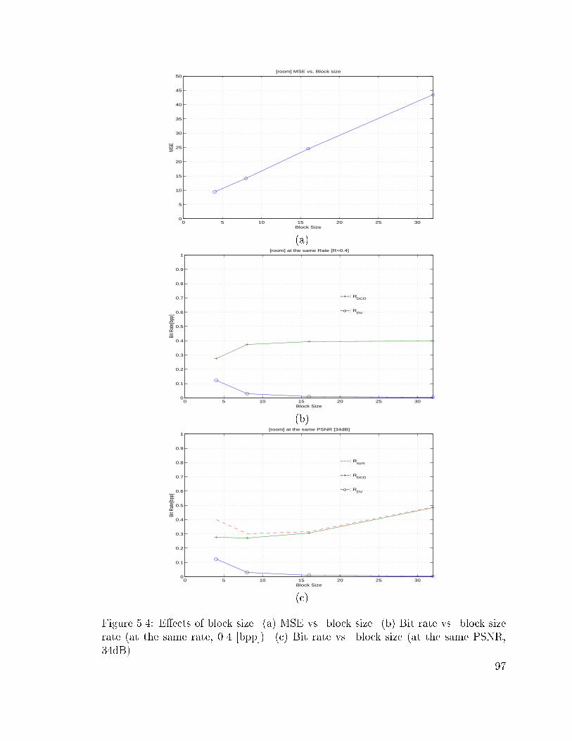
0 5 10 15 20 25 300
5
10
15
20
25
30
35
40
45
50[room] MSE vs. Block size
Block Size
MSE
(a)
0 5 10 15 20 25 300
0.1
0.2
0.3
0.4
0.5
0.6
0.7
0.8
0.9
1[room] at the same Rate [R=0.4]
Block Size
Bit R
ate[
bpp]
−+−: RDCD
−o−: RDV
(b)
0 5 10 15 20 25 300
0.1
0.2
0.3
0.4
0.5
0.6
0.7
0.8
0.9
1[room] at the same PSNR [34dB]
Block Size
Bit R
ate[
bpp]
−+−: RDCD
−o−: RDV
−−−: Rsum
(c)
Figure 5.4: E�ects of block size. (a) MSE vs. block size. (b) Bit rate vs. block size
rate (at the same rate, 0.4 [bpp]). (c) Bit rate vs. block size (at the same PSNR,
34dB).
97

Figure 5.5 compares the disparity estimation results of the proposed scheme versus
those of threshold-based VSBM. Figure 5.5 (a) and (b) show DV �elds based on the
FSBM. The resulting DV �eld of FSBM has a blocky appearance, as we are limited
to a single disparity vector per block. The errors occur, as expected, along the object
boundaries for the FSBM, where a di�erent estimate for object and background is
needed. The disparity �eld in Figure 5.5 (c) and (d) show DV �elds based on the
VSBM. As shown, VSBM shows inconsistencies in the DV �eld, as the sublock size
becomes small. As shown in (d), MRF-based DE in VSBM allows a consistent DV
�eld estimation.
(a) (b)
(c) (d)
Figure 5.5: Results of the disparity estimation for the synthesized image, Room. (a)
DV �eld with the FSBM (32� 32) (b) DV �eld with the FSBM (2� 2) (c) DV �eld
with the VSBM (32� 32 to 2� 2) (d) DV �eld with the proposed VSBM (32� 32 to
2� 2)
98

As expected, the proposed MRF model-based DE scheme estimates a relatively
smooth and accurate DV �eld, which can be used to generate intermediate scenes in
the virtual environment while reducing the disparity compensated error. The resulting
smooth disparity �eld reduces the bit rate for the disparity �eld itself. Figure 5.6
shows similar results for the natural images, Aqua.
(a) (b)
(c) (d)
Figure 5.6: Results of the disparity estimation for the natural image, Aqua. (a) DV
�eld with the FSBM (32� 32) (b) DV �eld with the FSBM (4� 4) (c) DV �eld with
the VSBM (32�32 to 4�4) (d) DV �eld with the proposed VSBM (32�32 to 4�4)
Figure 5.7 (a) and (b) show the corresponding RD plots of both target images
in the pairs of stereo images. In the experiments, we �x the reference image and
only measure the RD performance for the target images in the stereo pairs. The DV
�elds are encoded using Qtree and the DCD frames are encoded using JPEG. The
performance is measured in terms of PSNR. As shown, the proposed scheme achieves
99

a higher PSNR performance in both test images. Note however that the RD gain
of VSBM mainly comes from selectively segmenting the blocks according to some
\good" RD criteria.
According to our experimental results, the proposed hybrid VSBM method im-
proved overall encoding performance for the target image in a stereo pair. The DE
using (5.1) estimates relatively accurate and more consistent DV �elds, which re-
sults in less bit rate for the DV. The block segmentation using (5.3) reduces the
energy levels of the DCD frame. The encoding e�ciency has been further improved
by selectively applying OBDC for occlusion blocks, which signi�cantly reduces the
compensation error along the object boundaries. In terms of PSNR, the proposed
scheme achieved 0.5-1.5 dB higher PSNR, as compared with conventional VSBM,
at the same bit rates. In addition, the reconstructed image based on the proposed
scheme resulted in fewer annoying blocking artifacts, by reducing the blocking errors
along the subblocks using OBDC, the main drawback of the VSBM as well as FSBM
methods.
5.5 Discussion
We have proposed a hybrid coding scheme for stereo images, hierarchical DE/DC
with MRF model and selective OBDC. According to our experimental results, the
proposed scheme simultaneously solves the well-known problems of VSBM as well as
FSBM. The MRF-based hierarchical disparity estimation provides a smooth DV �eld
and the hierarchical block segmentation based on approximated RD cost reduces the
energy level of the DCD frame. Selective OBDC further reduced the energy level
of the DCD frame and blocking artifacts along subblock boundaries. As a result,
the proposed algorithm provides a higher PSNR as well as a better perceptual visual
quality.
100

0.3 0.4 0.5 0.6 0.7 0.8
31
32
33
34
35
36
37
38
39
[room] RD plot: FSBM vs. VSBM
PS
NR
[dB
]
Bit Rate[bpp]
−o−: HQBM16−4
−v−: VSBM16−4
(a)
0.3 0.4 0.5 0.6 0.7 0.8 0.9 1
24.5
25
25.5
26
26.5
27
27.5
[Aqua] RD plot: FSBM vs. VSBM
PS
NR
[dB
]
Bit Rate[bpp]
−o−: HQBM16−4
−v−: VSBM16−4
(b)
Figure 5.7: R-D Plot of reconstructed target images in the stereo pairs. (a) Room (b)
Aqua.
101

This research will be extended to the intermediate view generation (or synthesis)
to provide the look-around-capability at the decoder. The RD-based contour repre-
sentation of the segmented region remains a crucial future work because the RD-based
shape coding will be an important technique for object-based coding, providing vari-
ous functionalities such as interactive manipulation of objects.
102
Chapter 6
Summary and Future Extensions
6.1 Summary
In this research, the main focus has been on the e�cient representation of stereo
images, which is a simple way providing the 3D-depth information on a at 2D screen.
The transmission of stereoscopic images or sequences over existing channel requires
a very low rate coding of the additional stream in order to maintain the quality of
the reference image sequence. Such high compression ratio can only be achieved
by imposing structure to the additional sequence and taking advantage of the high
tolerance of the human visual system. The easiest extension would have been to
simply encode the reference image/sequence using JPEG/MPEG-type scheme and
the other image/sequence using disparity compensation method. To further improve
encoding e�ciency, we have proposed various encoding schemes within predictive
coding framework through this dissertation.
In Chapter 2, we surveyed various issues on 3D imaging systems and brie y re-
viewed research on stereo image/video coding. We then formulated the stereo im-
age coding problem using the dependent coding framework, consisting of estima-
tion/compensation, quantization, and rate control. Using the open loop coding sys-
tem, we decoupled the complicated joint optimization problem into two independent
problem; an e�cient disparity estimation and an optimal dependent quantization.
103

We �rst proposed a blockwise dependent quantization scheme in Chapter 3. With
a given DV �eld, we increased the coding e�ciency in quantization by taking into ac-
count the binocular dependency between the stereo pairs. The special dependency of
the stereo images was exploited to reduce the computational complexity. By exploit-
ing the predominant horizontal dimensional dependency, a compact dependency tree
was constructed per pairs of ROBs and then the optimal sets of quantizers had been
selected using the Viterbi algorithm. On the assumption of monotonicity property,
we also proposed a fast search algorithm for dynamic programming.
In Chapter 4 we explained the FSBM-based disparity estimation and its well-
known limitations. We then proposed a hybrid scheme to overcome those limitations.
The proposed hybrid scheme, MRF model-based disparity estimation and selective
overlapped block disparity compensation, provided a higher PSNR gain as well as
fewer visual artifacts. The MRF model helped provide smooth disparity �eld, while
maintaining the entropy of the disparity compensated di�erence. The selective OBDC
reduced the blocking artifacts in the reconstructed target. The incorporated half-pixel
accuracy further improved the encoding e�ciency.
In Chapter 5, we introduced the disparity estimation/compensation schemes based
on the VSBM to further reduce the entropy of the disparity compensated di�erence.
In the proposed method, the DV �eld was �rst estimated based on the MRF-based
cost function. Then, hierarchical block segmentation was performed by comparing
the RD costs of a block and its subsequent subblocks. Subsequently, overlapped block
disparity compensation is selectively performed for the occlusion blocks. Finally, the
resulting Qtree and the corresponding DV �eld were encoded. The DCD frame was
also encoded to improve the quality of the decoded target image.
6.2 Future Extensions
Stereo images can be encoded e�ciently by combining the disparity estimation and
the blockwise dependent quantization. These schemes can be extended easily into
104

stereo video coding. Based on the proposed algorithms in this thesis, the following
works are possible extensions.
6.2.1 Object-Oriented Segmentation Using Stereo Images
Object-oriented image segmentation is a key step in the upcoming new standards such
as MPEG-4 and MPEG-7. So far, a wide variety of image/video coding methods
have been developed but the main research activities on image/video coding have
concentrated on the �rst generation codec. Available �rst generation coding schemes
mainly exploit statistical redundancies of the image data and change parameters of
algorithms based on the blocks. The current image/video coding standards (JPEG,
H.26x, MPEG-1/2) belong to this category. However, most of these methods have
reached their limits in compression performance and have limitations when dealing
with real objects in a scene. They may fail to provide an acceptable quality, especially
at low rate coding, because annoying block artifacts become noticeable. Therefore,
more exible approaches are required.
Therefore, a novel object segmentation scheme using stereo images can help sep-
arate objects (or areas of interest) from a scene under assumption that pixels within
a rigid object have similar disparity vector. This scenario works under assumption
of 3D infrastructures, which require, at least, two cameras for 3D image/video cap-
ture [122]. Note however that even in 2D infrastructure, it provides look-around
capability based on intermediate scene synthesis [123].
6.2.2 RD-based Contour Coding
The main goal of segmentation-based coding is an e�cient representation of images,
i:e:, achieving the best visual quality for a given bit budget. An image can be seg-
mented into homogeneous regions and the segmented image can be represented by the
contours (or shapes of segmented regions), the textures (intensities) and the segmen-
tation errors, which then have to be encoded. The very same observed ideas can be
105
used to segment a disparity �eld or a motion vector �eld. the segmented regions can
be represented by global object descriptors such as the surface area, the perimeter,
the center of mass, the length and width, or the convexity. These type of parameters
are useful for object recognition and classi�cation but not for coding since such low
precision descriptions do not allow for a good reconstruction.
Other popular ways to represent the segmented regions are the region description
methods and the boundary description methods. In [53], we proposed a VSBM scheme
using the MRF model. The resulting DV �eld was segmented and encoded using
the chain coding method. To further increase the encoding e�ciency, we need RD-
based contour coding, which is a major problem in object-based coding. In general,
boundary also can be encoded using a lossy scheme and a lossless scheme [124{126].
Schuster et al [127, 128] proposed a RD-based boundary approximation using spline
and chain coding but they ignored the rate of the texture, which also has to be
considered. In addition, the bit allocation problem for the segmentation-based coding
is important. The bit budget has to be distributed between the contour description
and the segmentation error.
6.2.3 Blockwise Dependent Quantization for Video
The framework proposed in Chapter 3 can be directly extended into video coding
without the loss of generality. However, the temporal dependency is more complicated
because the direction of motion can be anywhere in 2D.
6.2.4 Joint Estimation of Motion and Disparity
Stereoscopic video consists of two image sequences, each sequence for a corresponding
eye. Therefore, there exists temporal redundancy between consecutive disparity map
sequence, which can help motion estimation of the reference sequence. It means that
the motion and the disparity have to be estimated jointly, which provide the consistent
motion and disparity �elds. Basically, disparity vector �eld can help estimate motion
106
vector �eld and vice versa. Therefore, it is interesting to combine information these
two �eld to increase reliability and to compensate the weakness of each method [5,56].
6.2.5 Multi-view Images and Intermediate-view Generation
The ideal 3D system has to provide images in space to allow for walking around and
viewing the object from all sides. In this sense, stereoscopic images are not the same
as 3D images because the viewing angle is strictly restricted to the position of stereo
cameras. These look-around capabilities can be achieved by multiview images. To
provide the look-around capability, the cameras have to move synchronously with the
viewers head, which is awkward. One solution is to use more cameras. However, it
also requires either a feedback signal from the end user to encoder or an increase in
the amount of data. the generation of intermediate scene at the decoder according
to the movement of head is one simple solution to this problem. Using the concepts
we used in the stereo image compression, we can synthesis the intermediate views.
107

Appendix A
3D Display Techniques
The basic idea of 3D display is to present simultaneously each image in a stereo pair
to the corresponding eye, i:e: to provide separately the left and right images to the
left and right eyes of the viewer, respectively. There are several ways to view 3D
scenes: Free-viewing, stereoscopic display, head-mounted display, autostereoscopic
display and holography. Note however that the two basic types are those that require
wearing glasses (stereoscopic display) and those that do not require wearing glasses
(autostereoscopic display).
A.1 Free Viewing and Stereoscope
The basic method for viewing pictures in stereo without special viewing devices is
called free-viewing. For example, 3D e�ects can be perceived by putting viewing
direction in parallel or crossing eyes to see the corresponding image, respectively.
Unfortunately, some people have problems in concentrating their eyes on stereo im-
ages. There may also be side e�ects such as eye stain, blur, and headaches to some
viewers. The classical stereoscope can help alleviate these pain in perceiving 3D by
removing the crosstalk between left and right eye views.
A.2 Stereoscopic Display
To perceive 3D scene on a 2D display monitor we have to produce or synthesize 2D
images by means of superimposing or temporal multiplexing.
� Anaglyphs and Pulfrich: Another popular and inexpensive method is
anaglyphic display (1850's) which is the oldest type of 3D viewing (red/blue)
glasses. Anaglyphs provide alternative method to represent stereo images,
where two views are encoded in di�erent colors and then each eye sees the
corresponding image through di�erent color �lter. For example, with anaglyph
techniques, the red (or cyan) �lters must coordinate with the blue (or green) of
the image. The next key is cancellation, which is the ability of the red �lter to
108
NOT see a red image, and the blue �lter to NOT see the blue image. This is the
weakest aspect of anaglyphs because it destroys the original color because the
color is used as a selection mechanism. Pulfrich is based on the same method
except colors of lenses (dark/clear lenses).
� Polarized display: Polarized (gray lenses) display is a more sophisticated
technique, where the two images in a stereo pair are encoded in orthogonal
polarization and then each eye sees the properly intended image through per-
pendicular polarizing �lters (or glasses). Polarization preserves color but is
sensitive to crosstalk (when the left eye sees the image for the right eye or vice
versa), because it utilizes the relative orientation of the polarized light. It is
used for projection situations such as theatrical 3D movies or in special venue
displays. These are comparatively expensive to manufacture because of two
things: the lens material and the handling of polarized images.
� Head Mounted Display (HMD): HMD is the best ALTERNATIVE where
the realism is not a concern, such as certain classes of video games. The resulting
the very low resolution is one of its major drawbacks.
� Sequential Display: The stereo image is displayed in time multiplexed se-
quence and the synchronization signal is passed to the shuttle glasses worn by
the viewer. The glasses are equipped with liquid crystal shutters switching from
opaque to clear: a shuttle alternately opens and closes in front of each eye as
the image changes on the monitor. For example, one of the lenses, the left one,
is made opaque (closed) so that the viewer can only see the right image on the
monitor through the right lens. Then, the situation is reversed, i:e: the right
lens is made opaque while the left view is displayed on the monitor. If the
images are displayed rapidly enough, then each eye perceives a di�erent image
from viewing the same monitor. For example, for a NTSC-based monitor with
a refresh rate of 60 Hz, each eye sees the image at a refresh rate of 30 Hz.
Therefore, for the icker-free 3D display a 120 Hz system is desirable.
A.3 Autostereoscopic Display
What autostereoscopic implies is a form of stereoscopic display that requires no glasses
or other aids for the viewer. With the advent of modern electronics, many methods
have become feasible, where each eye received a separated image.
Parallax Barrier Screen (PBS) and Lenticular Display: The picture behind the
PBS is composed of 2D images from di�erent viewing angles. Pixels for the left and
right images are displayed simultaneously in alternative columns. Each eye sees the
corresponding image through the appropriate stripes without special glasses. Lenticu-
lar Monitor uses cylindrical lenses, which is geometrically similar to PBS but provides
superior optical e�ciency.
109
The real limitation, however, of both autostereoscopic displays is in the image
quality. For example, the angular �eld of view is limited and each eye must be very
precisely positioned relative to the display. To meet those requirements, the display
system may require high display bandwidth, which is complex and expensive.
A.4 Hologram
To overcome �xed viewer position problems, 3D images have to be drawn into real
space. The most popular technique in depicting 3D scenes in space is holography.
Holograms are generated by splitting a laser light bundle in two parts, of which the
reference ray reaches 2D media (�lm) directly and the other is re ected from the
object onto the �lm. To record 3D images the �lm keeps only a phase di�erence, the
interference pattern of coherent laser beam (bright and dark lines holding the coded
spatial information), instead of a recognizable image. The 3D volume is displayed
directly into space without any stereoscopic tricks by the di�raction phenomenon
when the hologram is lit appropriately. They are fascinating new technologies but far
from practicality yet because of the huge amount of data. For example, an object of
a cubic (10� 10� 10 cm) with a 30 degree viewing angle requires a 25 Gbytes. Real
time video holography requires a further improvement in coding technique.
110

Appendix B
Stereo Images
(a) (b)
Figure B.1: Test stereo images Fruit. (a) left image (b) right image
111

(a) (b)
Figure B.2: Test stereo images Room. (a) left image (b) right image
(a) (b)
Figure B.3: Test stereo images Aqua. (a) left image (b) right image.
112
Reference List
[1] J. Hsu, C.F. Babbs, D.M. Chelberg, Z. Pizlo, and E.J. Delp, \Design of studies
to test the e�ectiveness of stereo imaging/ truth or dare: Is stereo viewing really
better?," in Proc. SPIE Stereoscopic Displays and Applications V, Feb. 1994,
vol. 2177A, pp. 211{222.
[2] T. Motoki, H. Isono, and I. Yuyama, \Present status of three-dimensional
television research," Proceedings of the IEEE, vol. 83, no. 7, pp. 1009{1021,
July 1995.
[3] M. Waldowski, \A new segmentation algorithm for videophone applications
based on stereo image pair," IEEE Trans. on Comm., vol. 39, no. 12, pp.
1856{1868, Dec. 1991.
[4] T. Aach and A. Kaup, \Disparity-based segmentation of stereoscopic fore-
ground/background image sequences," IEEE Trans. on Comm., vol. 42, no. 2,
pp. 673{679, Feb. 1994.
[5] E. Izquierdo, \Stereo matching for enhanced telepresence in three-dimensional
videocommunications," IEEE Trans. on CSVT, vol. 7, no. 4, pp. 629{643, Aug.
1997.
[6] D.P. Miller, \Evaluation of vision systems for teleoperated land vehicles," IEEE
Control Systems Magazine, pp. 37{41, June 1988.
[7] D. R. Shres, F.F. Holly, and P.G. Harnder, \High ratio bandwidth reduction of
video imaging for teleoperation," SPIE Image and Video Processing, vol. 1903,
pp. 236{245, Nov. 1993.
[8] M.W. Siegel, P. Gunatilake, S. Sethuraman, and A.G. Jordan, \Compression of
stereo image pairs and streams," in Proc. SPIE SDVRS, Feb. 1994, vol. 2177,
pp. 258{268.
[9] M. Stark, \Low cost universal stereoscopic virtual reality interfaces," in Proc.
SPIE Stereoscopic Displays and Applications, 1993, vol. 1915.
[10] B.G. Haskell, A. Puri, and A.N. Netravali, Digital Video: Introduction to
MPEG-2, The MIT Press, 1986.
113

[11] A. Puri, R. V. Kollarits, and B. G. Haskell, \Basics of stereoscopic video, new
compression results with MPEG-2 and a proposal for MPEG-4," J. on Signal
Processing: Image Comm., vol. 10, pp. 201{234, 1997.
[12] M. E. Lukacs, \Predictive coding of multi-viewpoint image sets," in Proc.
ICASSP, Oct. 1986, pp. 521{524.
[13] M. G. Perkins, \Data compression of stereopairs," IEEE Trans. on Comm.,
vol. 40, pp. 684{696, Apr. 1992.
[14] B. Julesz, Foundations of Cyclopeon Perception, The University of Chicago
Press, 1971.
[15] I. Dinstein, M.G. Kim, A. Henik, and J. Tzelgov, \Compression of stereo images
using subsampling transform coding," Optical Engineering, vol. 30, no. 9, pp.
1359{1364, Sept. 1991.
[16] V.S. Nalwa, A Guided Tour of Computer Vision, Addson-Wesley, 1993.
[17] B.K.P. Horn, Robot Vision, The MIT Press, 1986.
[18] R.E.H. Franich, Disparity Estimation in Stereo Digital Images, Ph.D. thesis,
TUDelft, 1996.
[19] U.R. Dohnd and J.K. Aggarwal, \Structure from stereo: A review," IEEE
Trans. on SMC, vol. 19, no. 6, pp. 1489{1510, June 1989.
[20] D. Marr and T. Poggio, \Cooperative computation of stereo disparity," Sci-
ence, vol. 194, pp. 283{287, 1976.
[21] B. Lucas and T. Kanade, \An iterative image registration technique with an
application to stereo vision," in Proc. of the 7th Int. J. Conf on AI, 1981, pp.
674{679.
[22] D. Marr and T. Poggio, \A computational theory of human stereo vision,"
Proc. of Roy. Soc. Lond., vol. B.204, pp. 301{328, 1979.
[23] T. Poggio, V. Torre, and C. Koch, \Computational vision and regularization
theory," Nature, vol. 317, pp. 314{319, 1985.
[24] P. Anandan, \A computational framework and an algorithm for the measure-
ment of visual motion," Int. J. of Computer Vision, vol. 2, pp. 283{310, 1989.
[25] J. Marroquin, S. Mitter, and T. Poggio, \Probabilistic solutions of ill-posed
problems in computational vision," J. of the Am. Stat. Soc., vol. 82, pp. 76{89,
1987.
114

[26] A. Yuille, \Energy functions for early vision and analog networks," Bio. Cyb.,
vol. 61, pp. 115{123, 1989.
[27] H. Jeong, W. Woo, C. Kim, and J. Kim, \A uni�cation theory for early vision,"
in Proc. First Korea-Japan Joint Conf. on the Computer, Oct. 1991, pp. 298{
309.
[28] J. Kim and H. Jeong, \Parallel relaxation algorithm for disparity compensa-
tion," IEE Electronics Letters, vol. 33, no. 6, pp. 1367{1368, July 1997.
[29] H.H. Baker and T.O. Binford, \Depth from edge and intensity-based stereo,"
in Proc. ICAI, 1981, pp. 631{636.
[30] D. Marr, Vision, San Francisco: Freeman, 1982.
[31] W.E.L. Grimson, \Computational experiments with a feature-based stereo al-
gorithm," IEEE Trans. on PAMI, vol. 7, no. 1, pp. 17{34, Jan. 1985.
[32] W. Ho� and N. Ahuja, \Surfaces from stereo: Integrating feature matching,
disparity estimation and contour detection," IEEE Trans. on PAMI, vol. 11,
no. 2, pp. 121{136, Feb. 1989.
[33] J. Weng, N. Ahuja, and T.S. Huang, \Matching two perspective views," IEEE
Trans. on PAMI, vol. 14, no. 8, pp. 806{825, Aug. 1992.
[34] D. Terzopoulos, \The computation of visible surface representation," IEEE
Trans. on PAMI, vol. 10, no. 4, pp. 417{438, July 1988.
[35] T.D. Sanger, \Stereo disparity computation using gabor �lter," Bio. Cyb., vol.
59, pp. 405{418, 1988.
[36] D.J. Fleet, A.D. Jepson, and M.R.M. Jenkin, \Phase-based disparity estima-
tion," CVGIP: Image Understanding, vol. 53, no. 2, pp. 198{210, Mar. 1991.
[37] P. Gunatilake, A.G. Jordan, and M.W. Siegel, \Compression of stereo video
streams," in SMPTE Proc. International Workshop on HDTV, Oct. 1993.
[38] I. Dinstein, G. Guy, and J. Rabany, \On the compression of stereo images:
Preliminary results," Signal Processing, vol. 17, no. 4, pp. 373{381, Aug. 1989.
[39] W. Woo and A. Ortega, \Blockwise dependent bit allocation for stereo image
coding," IEEE Trans. on CSVT, submitted, Apr. 1998, revised Oct. 1998.
[40] H. Aydinoglu, F. Kossentini, Q. Jiang, and M. H. Hayes, \Region based stereo
image coding," in Proc. IEEE ICIP, Washington, Oct. 1995, pp. 57{60.
[41] H. Aydinoglu and M. H. Hayes, \Stereo image coding: A projection approach,"
IEEE Trans. on IP, pp. 506{516, Apr. 1998.
115

[42] H. Aydinoglu and M. H. Hayes, \Performance analysis of stereo image coding
algorithms," in Proc. IEEE ICASSP, 1996, pp. 2191{2195.
[43] M.B. Slima, J. Konrad, and A. Barwicz, \Improvement of stereo disparity esti-
mation through balanced �ltering: The sliding-block approach," IEEE Trans.
on CSVT, vol. 7, no. 6, pp. 913{920, Dec. 1997.
[44] D. Tzovaras and M.G. Strintzis, \Motion and disparity �eld estimation using
Rate-Distortion optimization," IEEE Trans. on CSVT, vol. 8, no. 2, pp. 171{
180, Apr. 1998.
[45] W. Woo and A. Ortega, \Modi�ed overlapped block matching for stereo image
coding," in Proc. SPIE EI-VCIP, Jan. 1999, vol. 3653.
[46] M. Accame, F. G. De Natal, and D. D. Giusto, \Hierarchical block matching
for disparity estimation in stereo sequence," in Proc. IEEE ICIP, May 1993,
pp. 200{207.
[47] D. Tzovaras, S. Vachtsevanos, and M.G. Strintzis, \Optimization of quadtree
segmentation and hybrid two-dimensional and three-dimensional motion esti-
mation in a rate-distortion framework," IEEE J. on SAC, vol. 15, no. 9, pp.
1726{1738, Dec. 1997.
[48] G. J. Sullivan and R. L. Baker, \E�cient quadtree of images and video," IEEE
Trans. on IP, vol. 3, no. 3, pp. 327{331, May 1994.
[49] S. Sethuraman, M.W. Siegel, and A.G. Jordan, \A multiresolution framework
for stereoscopic image sequence compression," in Proc. IEEE ICIP, Oct. 1994,
vol. 2, pp. 361{365.
[50] S. Sethuraman, M.W. Siegel, and A.G. Jordan, \A multiresolution region based
segmentation scheme for stereoscopic image sequence compression," in Proc.
SPIE EI-Digital Video Compression: Algorithms and Technologies, Feb. 1995,
vol. 2419, pp. 265{274.
[51] S. Sethuraman, M.W. Siegel, and A.G. Jordan, \Segmentation based coding of
stereoscopic image sequences," in Proc. SPIE EI-Digital Video Compression:
Algorithms and Technologies, Jan. 1996, vol. 2668, pp. 420{429.
[52] M.W. Siegel, S. Sethuraman andJ. S. McVeigh, and A.G. Jordan, \Compres-
sion and interpolation of 3d-stereoscopic and multi-view video," in Proc. SPIE
SDVRS, Feb. 1997, vol. 3012, pp. 227{238.
[53] W. Woo and A. Ortega, \Stereo image compression based on the disparity �eld
segmentation," in Proc. SPIE EI-VCIP, Feb. 1997, vol. 3024, pp. 391{402.
116

[54] M. Kunt, A. Ikonomopoulos, and M. Kocher, \Second-generation image coding
techniques," Proc. of the IEEE, vol. 73, no. 4, pp. 549{574, Apr. 1985.
[55] F. Marques, M. Pardas, and P. Salembier, Coding-Oriented Segmentation of
Video Sequences, In Video Coding: The second Generation Approach, 1996.
[56] D. Tzovaras, N. Grammalidis, and M.G. Strintzis, \Object-based coding of
stereo image sequences using joint 3D motion/disparity compensation," IEEE
Trans. on CSVT, vol. 7, no. 2, pp. 312{327, Apr. 1997.
[57] S. Malassiotis and M.G. Strinzis, \Object-based coding of stereo image se-
quences using 3-D model," IEEE Trans. on CSVT, vol. 7, no. 6, pp. 892{905,
Dec. 1997.
[58] M.S. Moellenho� and M.W. Maier, \Transform coding of stereo image residu-
lals," IEEE Trans. on IP, vol. 7, no. 6, pp. 804{812, June 1998.
[59] W. Woo and A. Ortega, \Dependent quantization for stereo image coding," in
Proc. SPIE EI-VCIP, Jan. 1998, vol. 3309, pp. 902{913.
[60] N. Grammalidis and M.G. Strintzis, \Disparity and occlusion estimation in
multiocular systems and their coding for the communication of multiview image
sequences," IEEE Trans. on CSVT, vol. 8, no. 3, June 1998.
[61] J.L. Mannos and D.J. Sakrison, \The e�ects of a visual �delity criterion on the
encoding of images," IEEE Trans. Info. Theory, vol. 20, pp. 525{536, 1974.
[62] N.B. Nill, \A visual model weighted cosine transform for image compression
and quality assessment," IEEE Trans. on Comm., vol. 33, no. 6, pp. 551{557,
June 1985.
[63] A.B. Watson and M.P. Eckert, \Motion-contrast sensitivity: Visibility of mo-
tion gradients of various spatial frequencies," J. of the Opt. Soc. of America A,
pp. 496{505, 1994.
[64] S. Pei and C. Lei, \Vary low bit-rate coding algorithm for stereo video with
spatiotemporal HVS model and binary correlation disparity estimator," IEEE
Trans. on JSAC, vol. 16, pp. 98{107, Jan. 1998.
[65] R.M. Gray and D.L. Neuho�, \Quantization," IEEE Trans. on Info. Theory,
vol. 44, no. 6, Oct. 1998.
[66] C. Chen and K. Pang, \The optimal transform of motion-compensated frame
di�erence images in a hybrid coder," IEEE Trans. on CAS-II, vol. 40, no. 6,
pp. 393{397, June 1993.
117

[67] D.J. Connor and J.O. Limb, \Properties of frame-di�erence signals generated
by moving images," IEEE Trans. on Comm., vol. COM-22, no. 10, pp. 1564{
1575, Oct. 1974.
[68] R.C. Reininger and J. Gibson, \Distribution of the two-dimensional DCT coef-
�cients for images," IEEE Trans. on Comm., vol. 31, no. 6, pp. 835{839, June
1983.
[69] B. Girod, \The e�ciency of motion compensating prediction for hybrid coding
of video sequence," IEEE J. on S. Areas in Comm., vol. 5, no. 7, pp. 1140{1154,
Aug. 1987.
[70] P. Gerken and H. Schiller, \A low bit-rate image sequence coder combining a
progressive dpcm on interleaved rasters with a hybrid DCT technique," IEEE
J. on S. Areas in Comm., vol. 5, no. 7, pp. 1079{1089, Aug. 1987.
[71] A. Puri and R. Aravind, \Motion-compensated video coding with adaptive
perceptual quantization," IEEE Trans. on CSVT, vol. 1, no. 4, pp. 351{361,
Dec. 1991.
[72] C. Chu and K. Aggarawal, \The integration of image segmentation maps using
region and edge information," IEEE Trans. on PAMI, vol. 15, no. 12, pp.
1241{1252, Dec. 1993.
[73] C.A. Gonzales and E. Viscito, \Motion video adaptive quantization in the
transform domain," IEEE Trans. on CSVT, vol. 1, no. 4, pp. 374{378, Dec.
1991.
[74] C. Stiller and D. Lappe, \Laplacian pyramid coding of prediction error images,"
in Proc. SPIE VCIP, 1991.
[75] J.M. Shapiro, \Embedded image coding using zerotrees of wavelet coe�cients,"
IEEE Trans. On signal Processing, vol. 41, no. 12, pp. 3445{3462, Dec. 1993.
[76] F. Muller and K. Illgner, \Embedded pyramid coding of displaced frame dif-
ference," in Proc. IEEE ICIP, 1995.
[77] H. Samet and M. Tamminen, \Computing geometric properties of images rep-
resented by linear quadtrees," IEEE Trans. on PAMI, vol. 7, no. 2, pp. 229{240,
Mar. 1985.
[78] L.E. Davission, \Rate-Distortion theory and application," Proceeding of the
IEEE, vol. 7, no. 60, pp. 800{808, July 1972.
[79] T.M. Cover and J.A. Thomas, Elements of Information Theory, Wiley-
Interscience, 1991.
118
[80] K. Ramchandran, A. Ortega, and M. Vetterli, \Bit allocation for dependent
quantization with applications to multiresolution and MPEG video coders,"
IEEE Trans. on IP, vol. 3, no. 5, pp. 533{545, Sept. 1994.
[81] A. Ortega, Optimization Techniques for Adaptive Quantization of Image and
Video Under Delay Constraints, Ph.D. dissertation, Dept. of EE, Columbia
Univ., 1994.
[82] Y. Shoham and A. Gersho, \E�cient bit allocation for an arbitrary set of
quantizers," IEEE Trans. on ASSP, vol. 36, pp. 1445{1453, Sept. 1988.
[83] S. Geman and D. Geman, \Stochastic relaxation, Gibbs distributions and the
bayesian restoration of images," IEEE Trans. on PAMI, pp. 721{741, Nov.
1984.
[84] J.E. Besag, \Spatial interaction and the statistical analysis of lattice systems,"
J. Royal Statistical. Soc., vol. B36, pp. 192{236, 1974.
[85] N. M. Nasrabadi, S. P. Cli�ord, and Y. Liu, \Integration of stereo vision
and optical ow by using an energy minimizing approach," Optical Society of
America, vol. 6, pp. 900{907, June 1989.
[86] W. Woo and A. Ortega, \Stereo image compression based on the disparity
compensation using the MRF model," in Proc. SPIE VCIP, Mar. 1996, vol.
2727, pp. 28{41.
[87] W.C. Chung, F. Kossentini, and M.J.T. Smith, \Rate-Distortion constrained
statistical motion estimation for video coding," in Proc. IEEE ICIP, Oct. 1995,
pp. 184{187.
[88] J. Ribas-Corbera and D. Neuho�, \Optimal bit allocations for lossless video
coders: Motion vectors vs. di�erence frames," in Proc. IEEE ICIP, Oct. 1995,
pp. 180{183.
[89] G. M. Schuster and A. K. Katsaggelos, \A theory for the optimal bit allocation
between displacement vector �eld and displaced frame di�erence," IEEE Jr.
on Sel. Areas in Comm., vol. 15, no. 9, pp. 13{26, Dec. 1997.
[90] M.C. Chen and A.N. Willson Jr., \Rate-Distortion optimal motion estimation
algorithm for motion-compensated transform video coding," IEEE Trans. On
CSVT, vol. 8, no. 2, pp. 147{158, Apr. 1998.
[91] L.J. Lin and A. Ortega, \Bit-rate control using piecewise approximated Rate-
Distortion characteristics," IEEE Trans. on CSVT, vol. 8, no. 4, pp. 486{499,
Aug. 1998.
119
[92] T. Wiegand, M. Lightstone, D. Mukherjee, T.G. Campbell, and S.K. Mitra,
\Rate-distortion optimized mode selection for very low bit-rate video coding
and the emerging H.263 standard," IEEE Trans. on CSVT, vol. 6, no. 2, pp.
182{190, Apr. 1996.
[93] H. Everett, \Generalized Lagrange multiplier method for solving problems of
optimum allocation of resources," Operational Res., vol. 11, pp. 399{417, 1963.
[94] G.L. Nemhauser and L.A. Wolsey, Integer and Combinatorial Optimization,
Wiley, 1988.
[95] G.D. Forney, \The Viterbi algorithm," The Proc. IEEE, vol. 61, pp. 268{278,
Mar. 1973.
[96] W. Pennebaker and J. Mitchell, JPEG Still Image Compression Standard, Van
Nostrand Rheinhold, 1994.
[97] B.L. Tseng and D. Anastassiou, \Multi-viewpoint video coding with mpeg-2
compatibility," IEEE Trans. on CSVT, vol. 6, no. 4, pp. 414{419, Aug. 1996.
[98] K. Illgner and F. Muller, \Motion estimation using overlapped block motion
compensation and Gibbs-modeled vector �elds," in Proc. IEEE IMDSP, Mar.
1996, pp. 126{127.
[99] H. Watanabe and S. Singhal, \Windowed motion compensation," in Proc.
SPIE VCIP, Nov. 1991, vol. 1605, pp. 582{589.
[100] M. Orchard and G. Sullivan, \Overlapped block motion compensation: An
estimation-theoretic approach," IEEE Trans. on IP, vol. 5, no. 3, pp. 693{699,
1994.
[101] H. Dankworth and W. Niehsen, \Analytical overlapped block motion compen-
sation," in Proc. NORSIG97, 1997, pp. 75{80.
[102] R. Rajagopalan, E. Feig, and M.T. Orchard, \Motion optimization of ordered
blocks for overlapped block motion compensation," IEEE Trans. on CSVT,
vol. 8, no. 2, pp. 119{123, Apr. 1998.
[103] S. Nogaki and M. Ohta, \An overlapped block motion compensation for high
quality motion picture coding," in Proc. IEEE ISCAS, 1992.
[104] J.K.Su and R.M. Mersereau, \Non-iterative Rate-constrained motion estima-
tion for OBMC," in Proc. IEEE ICIP, 1997, pp. 33{36.
[105] T. Kuo and C. Kuo, \Complexity reduction for overlapped block motion com-
pensation," in Proc. SPIE EI-VCIP, Feb. 1997, vol. 3024, pp. 303{314.
120

[106] T. Kuo and C. Kuo, \A hybrid BMC/OBMC motion compensation scheme,"
in Proc. IEEE ICIP, Oct. 1997, vol. 2, pp. 795{798.
[107] B. Tao and M.T. Orchard, \Joint application of overlapped block motion com-
pensation and loop �eltering for low bit-rate video coding," in Proc. IEEE
ICIP, 1997.
[108] B. Girod, \Motion-compensating prediction with fractional-pel accuracy,"
IEEE Trans. on Comm., vol. 41, no. 4, pp. 604{611, Apr. 1993.
[109] K. Illgner and F. Muller, \Analytical analysis of subpel motion compensation,"
in Proc. PCS, 1997, pp. 135{140.
[110] W. Woo and A. Ortega, \Block-based disparity estimation and compensation
for stereo image coding," IEEE Trans. on CSVT, In preparation, 1999.
[111] A. Puri, H.M. Hang, and D.L. Schilling, \Interframe coding with variable
block-size motion compensation," in GLOBECOM, Nov. 1987, pp. 65{69.
[112] M. T. Orchard, \Predictive motion-�eld segmentation for image sequence cod-
ing," IEEE Trans. on SP, vol. 41, no. 12, pp. 3416{3424, Dec. 1993.
[113] J. Kim and S. Lee, \Hierachical variable block size motion estimation technique
for motion sequence coding," SPIE Optical Engineering, vol. 33, no. 8, pp.
2553{2561, Aug. 1994.
[114] G. Hunter and K. Steiglitz, \Operations on images using quad trees," IEEE
Trans. on PAMI, vol. 1, no. 2, pp. 145{153, Apr. 1979.
[115] P.A. Chou, T. Lookabaugh, and R.M. Gray, \Optimal pruning with applica-
tions to tree-structured source coding and modeling," IEEE Trans. on Inform.
Theory, vol. 35, pp. 299{315, Mar. 1989.
[116] F. Moscheni, F. Dufaux, and H. Nicolas, \Entropy criterion for optimal bit
allocation between motion and prediction error information," in Proc. SPIE
VCIP, Nov. 1993, pp. 235{242.
[117] J. Lee, \Optimal quadtree for variable block size motion estimation," in Proc.
IEEE ICIP, Oct. 1995, vol. 3, pp. 480{483.
[118] Y. Yang and S. Hemami, \Rate-constrained motion estimation and perceptual
coding," in Proc. IEEE ICIP, 1997, pp. 81{84.
[119] H. Bi and W. Chan, \Rate-Distortion optimization of hierarchical displacement
�elds," IEEE Trans. on CSVT, vol. 8, no. 1, pp. 18{24, Feb. 1998.
121
[120] J. Hartung, A. Jacquin, J. Pawlyk, J. Rosenberg, H. Okada, and P.E. Crouch,
\Object-oriented h.263 compatible video coding platform for conferencing ap-
plications," IEEE Trans. on JSAC, vol. 16, no. 1, pp. 42{55, Jan. 1998.
[121] A. Ortega, K. Ramchandran, and M. Vetterli, \Optimal trellis-based bu�ered
compression and fast approximation," IEEE Trans. on IP, vol. 3, no. 1, pp.
26{40, Jan. 1994.
[122] K. Kim, M.W. Siegel, and J. Son, \Synthesis of a high resolution 3d-stereoscopic
image from a high resolution monoscopic image and a low resolution depth
map," in Proc. SPIE Stereoscopic Displays and Virtual Reality Systems V,
Jan. 1998, vol. 3095, pp. 76{86.
[123] B.L. Tseng and D. Anastassiou, \A theoretical study on an accurate recon-
struction of multiview images based on the viterbi algorithm," in Proc. IEEE
ICIP, 1995.
[124] T. Kaneko and M. Okudaira, \Encoding of arbitrary curves based on the chain
code representation," IEEE Trans. on Comm., vol. 33, no. 7, pp. 697{707, July
1985.
[125] A.K. Jain, Fundamentals of Digital Image Processing, Prentice-Hall, 1989.
[126] C. Lu and J.G. Dunham, \Highly e�cient coding scheme for contour lines
based on chain code representations," IEEE Trans. on Comm., vol. 39, no. 10,
pp. 1511{1514, Oct. 1991.
[127] G. M. Schuster and A. K. Katsaggelos, \An e�cient boundary encoding scheme
which is optimal in the rate distortion sense," in Proc. IEEE ICIP, Sept. 1996,
pp. 77{80.
[128] G. M. Schuster and A. K. Katsaggelos, \An optimal polygonal boundary en-
coding scheme in the rate distortion sense," IEEE Trans. on IP, vol. 7, no. 1,
pp. 13{26, Jan. 1998.
122