orthomode transducer for the new w-band receiver …orthomode transducer for the new w-band receiver...
TRANSCRIPT
Orthomode transducer for the new W-band receiver of
the 40 m radio telescope Ó. García-Pérez, F. Tercero, S. López-Ruiz
CDT Technical Report 2018-09
Observatorio de Yebes 19080, Guadalajara (Spain)
E-mail: [email protected]
Abstract– A new HEMT-based dual-polarized W-band receiver will be installed at the Yebes 40 m radio telescope, covering the frequency range from 72 to 90.5 GHz. This report presents the development and characterization of an orthomode transducer (OMT) that will be part of such receiver.
June, 2018

2

3
Contents Contents ............................................................................................................................. 3
1 Introduction ................................................................................................................... 4
2 Design and simulation ..................................................................................................... 5
3 Fabrication and measurement ......................................................................................... 8
4 Conclusion .................................................................................................................... 11
References ........................................................................................................................ 12
Appendix A: External interface ........................................................................................... 13

4
1 Introduction New Q and W band receivers will be installed at the Yebes 40 m radio telescope. In the short term, this change is motivated by the Nanocosmos project, which aims to combine astronomical observations with modeling and top-level experiments to produce star dust analogues in the laboratory and identify the key species and steps that govern their formation [1]. Consequently, improved levels of sensitivity and bandwidth are required for the antenna observations.
An essential part for the implementation of these receivers is the orthomode transducer (OMT), which is the passive component that separates the incoming electromagnetic signal into two orthogonal polarizations. The implementation of a new Q band (31.5-50 GHz) OMT was already reported in [2]. This document presents the implementation of an OMT for the new W band (i.e., 72-90.5 GHz) receiver of the 40 m radio telescope.

5
2 Design and simulation The geometrical topology proposed for the OMT is depicted in Fig. 2.1, which follows the structure presented in [3]. It is a T-shaped waveguide, in which the two orthogonal linear polarizations coming from a square input port (port 1) are split into two separated rectangular ports (ports 2 and 3 respectively). Due to its simplicity, it can be easily fabricated from a two-block assembly, which is adequate for submillimeter frequencies. However, it is symmetrical about only one plane (XY according to Fig. 2.1), so its maximum frequency will be limited by coupling into higher order modes (i.e., TE11 and TM11).
Fig. 2.1: Simplified model of the OMT.
In this case, the frequency range of interest is between 72 and 90.5 GHz. Accordingly, rectangular output ports have been chosen to be compatible to standard WR-10 waveguide section (2.54 x 1.27 mm). For convenience, the dimension of the square waveguide has been set to 2.54 x 2.54 mm.
Starting from a scaled version of the solution presented in [3], the geometrical parameters have subsequently been optimized with CST Studio Suite to achieve the desired performance at the frequencies of interest. The internal edges have been rounded by a radius of 300 µm to take into account the dimension of the milling cutter for the manufacturing.

Orthomode transducer for the new W-band receiver of the 40 m radio telescope
6
Before the T-branch, the square section of the input port is progressively reduced down to 2.2 x 2.2 mm. Such dimension determines the cut-off frequencies of the waveguide modes that can be propagated along the component, and therefore the bandwidth of the OMT. In this case, the cutoff frequency of the fundamental TE10 mode is about 68.2 GHz. There is still a margin with respect to the desired minimum frequency (i.e., 72 GHz) since in practice it is difficult to achieve acceptable return losses very close to the cutoff frequency. On the other hand, the cutoff frequency of the TE11 and TM11 modes is about 96.4 GHz, which states the practical higher frequency limit.
The simulated S-parameters of the optimized OMT are shown in Fig. 2.2. Apart from the fundamental TE10 modes, additional higher order modes TE11 and TM11 have been considered for the square input port 1. Regarding the 72-90.5 GHz frequency band, the reflection coefficients are below -25 dB, and the transmission losses between input
Fig. 2.2: Simulated S-parameters of the OMT.
70 75 80 85 90 95 100 105 110Frequency (GHz)
-50
-40
-30
-20
-10
0
Ref
lect
ion
(dB)
s22s33
70 75 80 85 90 95 100 105 110Frequency (GHz)
-30
-25
-20
-15
-10
-5
0
Tran
smis
sion
(dB
)
s21 (TE01 at port 1)
s31 (TE10 at port 1)s21 (TE11 at port 1)
s21 (TM11 at port 1)

2 Design and simulation
7
and output ports are less than 0.1 dB. At high frequencies, well above the higher frequency of interest, some effects related to higher order modes appear. As it can be observed in the transmission, at frequencies above about 96 GHz there is a noticeable coupling between the higher order modes at port 1 and the fundamental mode at port 2. However, this does not occur with port 3.
In order to analyze the propagation of different electromagnetic modes within the component, the electric field distribution of the different modes at the square and rectangular ports has been represented in Fig. 2.3. As it was mentioned before, the structure presents a single geometric plane of symmetry, which corresponds to the XY plane in the representation shown in Fig. 2.1. In the case of the side path, the field distribution of the TE10 mode at the output port 2 presents a perfect magnetic conductor (PMC) symmetry condition at the intersection with the XY-plane. On the other hand, in the through path, the field of the TE10 mode at port 3 presents a perfect electric conductor (PEC) symmetry condition at the intersection with the XY plane. With regard to input port 1, the field distributions of higher order modes TE11 and TM11 have both PMC symmetries at the horizontal and vertical axes. Since electrical symmetry conditions are kept along the structure when they are coincident with a global geometric plane of symmetry, coupling between input TE11/TM11 and output TE10 modes is only possible for the case of port 2 (side path), since PMC condition is maintained at the XY plane.
Fig. 2.3: Electric field distributions at the OMT waveguide ports.
TE01
TE10
TE01
TE10
TE11
TM11
Port #1 Port #2
Port #3
PEC - - PMC — Symetry plane
yz
xz
yz

8
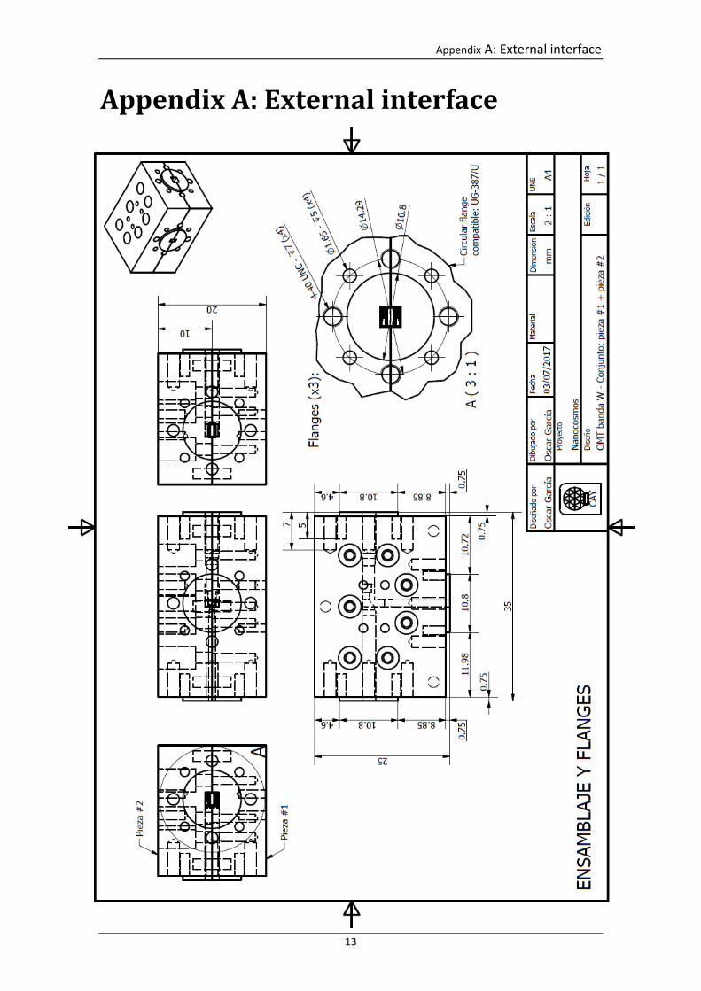
3 Fabrication and measurement Two samples of the designed OMT have been manufactured (see Fig. 3.1). Each OMT is composed of two gold-plated brass blocks, and the overall outer dimensions are 35 x 25 x 20 mm. Several precision pins have been used to facilitate the alignment of both blocks during assembly. The waveguide flanges have been defined to be compatible to UG-387/U specification. External interface dimensions are in Annex A.
The measured results of both implemented OMTs are presented in Fig. 3.2 and Fig. 3.3 respectively. The reflection and isolation have been measured connecting the VNA millimeter heads between ports 2 and 3, whereas port 1 has been loaded using a horn antenna [4] as matched load. Within the band of interest (i.e., 72-90.5 GHz), reflection is less than -14 dB and isolation is more than 35 dB for both units. As it was also observed from simulations, coupling into higher order modes degrade the reflection coefficient seen from port 2 above 96 GHz. Transmission losses have been estimated by short-circuiting port 1, and measuring the reflected power at each port. Assuming total reflection at the metal plate and good isolation between ports 2 and 3, transmission losses for each path can be approximated as half of the reflected power at each port. In this case, the obtained insertion loss is about 0.5 dB in average, and 0.8 dB in the worst point.
Fig. 3.1: Photograph of the manufactured OMTs.

3 Fabrication and measurement
9
Fig. 3.2: Measured S-parameters of the manufactured OMT #1.
70 75 80 85 90 95 100 105 110Frequency (GHz)
-50
-40
-30
-20
-10
0
Ref
lect
ion
(dB)
OMT #1
s22s33
70 75 80 85 90 95 100 105 110Frequency (GHz)
-2
-1.5
-1
-0.5
0
Tran
smis
sion
(dB
)
s21s31
70 75 80 85 90 95 100 105 110Frequency (GHz)
-50
-40
-30
-20
-10
0
Isol
atio
n (d
B)
s32

Orthomode transducer for the new W-band receiver of the 40 m radio telescope
10
Fig. 3.3: Measured S-parameters of the manufactured OMT #2.
70 75 80 85 90 95 100 105 110Frequency (GHz)
-50
-40
-30
-20
-10
0
Ref
lect
ion
(dB)
OMT #2
s22s33
70 75 80 85 90 95 100 105 110Frequency (GHz)
-2
-1.5
-1
-0.5
0
Tran
smis
sion
(dB
)
s21s31
70 75 80 85 90 95 100 105 110Frequency (GHz)
-50
-40
-30
-20
-10
0
Isol
atio
n (d
B)
s32

11
4 Conclusion Due to its simple and compact geometry, T-junction OMTs are easy to fabricate and therefore adequate for submillimeter frequencies. His main drawback is its modest bandwidth (about 1.35:1) compared to other topologies, which is limited by the coupling into higher order modes due to its one-fold symmetry. In this case, an OMT working at W band has been successfully designed and implemented. Although initial specifications aimed to cover from 72 to 90.5 GHz, the implemented solution demonstrates good performance up to about 95 GHz.

12
References [1] Nanocosmos project. [Online]. Available: https://nanocosmos.iff.csic.es/ [2] S. López-Ruiz, F. Tercero, M. G. Núñez, J. A. López-Fernández, “31.5 GHz-50.0 GHz
ortho-mode transducer for the Nanocosmos receiver in the 40m Radiotelescope,” CDT Technical Report 2017-1, 2017.
[3] A. Dunning, S. Srikanth, A. R. Kerr, “A simple orthomode transducer for centimeter to submillimeter wavelengths,” 20th International Symposium on Space Terahertz Technology, Apr. 2009.
[4] F. Tercero, O. García-Pérez, “Design of Q and W band feeds for Nanocosmos Project,” CDT technical Report 2018-8, 2018.
Appendix A: External interface
13
Appendix A: External interface