osar scsi command reference - plasmon tech · osar scsi command reference responsible engineer:...
TRANSCRIPT

3565 Harbor Boulevard Costa Mesa, California 92626
OSAR SCSI Command Reference
Responsible Engineer: Joel Kirscher
Manager,
Hardware Engineering: John Cecka
Filed: \CM-OPS1\Data\hardware\prodspec\9000238M.doc
This document contains information proprietary to FileNET Corporation, and may not be reproduced in whole or in part by any means without the prior written consent of FileNET Corporation. This document is only conditionally issued, and neither receipt nor possession hereof confers or transfers any right in, or license to use any or all of the subject matter contained herein.
DWG: 9000238 Rev:M DATE: July 14, 2003
SHEET: 1 of 41
Specification: 9000238 Rev: M

OSAR SCSI Command Reference
REVISION HISTORY
REV. ECO DESCRIPTION DATE A 4476 Initial Release 10/18/94 B 4556 Production Release 2/10/95 C 700387 Added commands; Reserve, Release, Position to Element, Prevent Allow
Medium Removal and I/O Station Lock and some new error and backup codes. Removed support for models 0140 and 0161. Changed the Additional Sense Bytes Format. Changed the element addresses. Removed Receive Diagnostic Results command and changed the Inquiry data format to report the revision levels and the serial number.
8/22/96
D 700439 Corrected typographical errors, pages. 22 & 30 - JEC 9/16/96 E 700925 Added Mode Select Command
Added Modes Sense Pages Removed Appendix - Error Code Table Removed Appendix - Backup Code Table Corrected typographical errors Remove Medium Error from list of Sense Keys. Added Save Data pointer message to the Messages table. Changed page numbering format Updated the list of SCSI Errors Added Aborted Commands to the Sense Key Table Made format of tables consistent Added table labels and a list of Tables Added Error Recovery section
3/11/97
F 702625 General cleanup of document to improve readability Changed "CE" to "FE", "Customer Engineer" to "Field Engineer", "host" to "initiator", "unit of media" to "cartridge" Remove "field", when appropriate, from Command descriptions. Added SingleGrip and SingleHolds bits to Request Sense Data byte 54. Added SingleGrip and SingleHolds to Additional Sense Bytes Format description. Added Page Code and Allocation Length to Inquiry Command description. Added Block Descriptor Length to Mode Select Command description. Added Block Description Length to Mode Select Parameter List description. Added Allocation Length to Mode Sense CDB description. Added Mode Data Length to Mode Parameter Header description. Added Transport Element Address to Move Medium CDB and Position To Element CDB descriptions. Added Except and Full to Storage Element Descriptor description in the Read Element Status command. Added Full to Import/Export Element Descriptor description in the Read Element Status command. Added Third Party Device ID to Release CDB description. Added Element List Length to Reserve CDB description.
1/18/00
G 702715 Added a new SCSI Error - Sense Key = 2, Additional Sense Code = 4, Additional Sense Code Qualifier = 2; See Table 39, page 26 Replaced references to GTX and GTL with GTS/HTS, pages 6 and 12
4/20/2000
Specification: 9000238 Rev: M ii

OSAR SCSI Command Reference
H 702773 Defined bytes 20, 21, & 22 in Request Sense Data to be three Field Action Fields and wrote descriptions for these fields. In Table 41 changed the names for the Source, Destination and Secondary Destination Element Fields from Number to Address. Added text descriptions to the Request Sense Data for the following fields: Source Element Address, Destination Element Address, Secondary Destination Element Address, Odometer, Library Communications Log Length and Library Communications Log Changed FileNet to FileNET throughout the document. Added ‘Element’ to Source Element Address and Destination Element Address in the Move Medium description text. Added ‘Element’ to Destination Element Address in the Position To Element CDB Block and description text. Some text was revised to remove grammatical errors.
6/22/2000
J 703336 Added Revision bytes of SCSI Translator to Request Sense Data bytes 30 to 31. Added Revision bytes of the OSAR Library to Request Sense Data bytes 32 to 33. Changed the labels of the bits in the text describing the Request Sense Data for bytes 55 to 57. Changed the text describing the bits in the Request Sense Data for bytes 55 to 57. Corrected text for the Request Sense Codes. For Sense Key = 0x01 and Additional Sense Code = 0x40 and for the Additional Sense Code Qualifiers = 0x81 to 0x84 the text was changed. Previous text said Logical Unit Not Ready. This is not correct; a single fan failure does not make the unit inoperable. Changed the description of bytes 58 and 59 in the Request Sense data; byte 58 is reserved and 59 is the length of the dialogue. Changed the Request Sense Data bytes 34-49 from reserved to contain checkpoint debug data. Added text to describe Diagnostic Function Code. Added text to describe Diagnostic Function Code. Added a byte to the Request Sense data (byte 49) to describe the bit switch settings.
5/03/2002
K 703497 Added descriptions to Table 39 Error Sense Codes. Added 2, 4, 0 LUN Not Ready check condition. Added 4, 4, 88 LUN Not Ready- Wrong Configuration check condition. Removed the Approval column from the Revision History Table.
5/24/2002
L 703653 Added some explanation of how sense data is logged in Library Communications Log (bytes 60 to 255max) of the Request Sense command.
10/15/2002
Specification: 9000238 Rev: M iii

OSAR SCSI Command Reference
M 703932 Changed the Additional Length, byte 5, field of the Inquiry data. It was changed to be 0x2B. Also, the Additional Length description text was changed.
7/14/2003
Specification: 9000238 Rev: M iv

OSAR SCSI Command Reference
Table of Contents
1. INTRODUCTION ................................................................................................................ 1
1.1 Definitions......................................................................................................................................................................... 1
1.2 References......................................................................................................................................................................... 1
1.3 SCSI Translator Architecture......................................................................................................................................... 1
1.4 Error Recovery ................................................................................................................................................................ 1
2. COMMANDS ...................................................................................................................... 2
2.1 Exchange Medium Command (A6h) .............................................................................................................................. 2
2.2 Initialize Element Status Command (07h) ..................................................................................................................... 4
2.3 Inquiry Command (12h).................................................................................................................................................. 4
2.4 I/O Station Lock Unlock Command (0Ch) .................................................................................................................... 8
2.5 Mode Select Command (15h) .......................................................................................................................................... 8 2.5.1 Gripper Enable/Disable Page ..................................................................................................................................... 9
2.6 Mode Sense Command (1Ah)........................................................................................................................................ 10 2.6.1 Mode Parameter Header .......................................................................................................................................... 11
2.7 Move Medium Command (A5h) ................................................................................................................................... 16
2.8 Position To Element command (2Bh)........................................................................................................................... 17
2.9 Prevent Allow Medium Removal Command (1Eh)..................................................................................................... 18
2.10 Read Element Status Command (B8h)......................................................................................................................... 19
2.11 Release Command (17h) ................................................................................................................................................ 24
2.12 Request Sense Command (03h)..................................................................................................................................... 24
2.13 Reserve Command (16h) ............................................................................................................................................... 32 2.13.1 Reserve Command Element List Descriptors........................................................................................................... 32
2.14 Rezero Unit Command (01h) ........................................................................................................................................ 33
2.15 Send Diagnostic Command (1Dh)................................................................................................................................. 34
2.16 Test Unit Ready Command (00h) ................................................................................................................................. 39
3. MESSAGES ..................................................................................................................... 40
4. DISCONNECTS................................................................................................................ 40
Specification: 9000238 Rev: M v
OSAR SCSI Command Reference
5. STATUS ........................................................................................................................... 41
Specification: 9000238 Rev: M vi

OSAR SCSI Command Reference
TABLES Table 1 Exchange Medium CDB ..................................................................................................................................................... 2 Table 2 Initialize Element Status CDB ............................................................................................................................................ 4 Table 3 Inquiry CDB ....................................................................................................................................................................... 4 Table 4 Inquiry Command Returned Data ....................................................................................................................................... 5 Table 5 Peripheral Qualifier ............................................................................................................................................................ 6 Table 6 Peripheral Device Type ...................................................................................................................................................... 6 Table 7 Product Identification Field ................................................................................................................................................ 6 Table 8 I/O Station Lock CDB ........................................................................................................................................................ 8 Table 9 Mode Select CDB............................................................................................................................................................... 8 Table 10 Mode Select Parameter List .............................................................................................................................................. 9 Table 11 Mode Select Page Codes .................................................................................................................................................. 9 Table 12 Gripper Enable/Disable Page............................................................................................................................................ 9 Table 13 Mode Sense CDB ........................................................................................................................................................... 10 Table 14 Page Control Field .......................................................................................................................................................... 10 Table 15 Mode Page Codes ........................................................................................................................................................... 10 Table 16 Mode Parameter Header ................................................................................................................................................. 11 Table 17 Element Address Assignment Page - Dual Gripper ........................................................................................................ 11 Table 18 Element Address Assignment Page - Single Gripper...................................................................................................... 12 Table 19 Number of Storage Elements and Data Transfer Elements............................................................................................. 12 Table 20 Transport Geometry Parameters Page............................................................................................................................. 12 Table 21 Device Capabilities Page - Dual Grippers ...................................................................................................................... 14 Table 22 Device Capabilities Page - Single Gripper ..................................................................................................................... 14 Table 23 Gripper Enable/Disable Page.......................................................................................................................................... 15 Table 24 Move Medium CDB ....................................................................................................................................................... 16 Table 25 Position To Element CDB .............................................................................................................................................. 17 Table 26 Prevent Allow Medium Removal CDB .......................................................................................................................... 18 Table 27 Read Element Status CDB .............................................................................................................................................. 19 Table 28 Element Type Code ........................................................................................................................................................ 19 Table 29 Read Element Status Data............................................................................................................................................... 20 Table 30 Element Status Page........................................................................................................................................................ 20 Table 31 Medium Transport Element Descriptor .......................................................................................................................... 21 Table 32 Storage Element Descriptor ............................................................................................................................................ 21 Table 33 Import/Export Element Descriptor ................................................................................................................................. 21 Table 34 Data Transfer Element Descriptor .................................................................................................................................. 22 Table 35 Release CDB................................................................................................................................................................... 24 Table 36 Request Sense CDB........................................................................................................................................................ 24 Table 37 Request Sense Data......................................................................................................................................................... 25 Table 38 Sense Keys...................................................................................................................................................................... 25 Table 39 Error Sense Codes .......................................................................................................................................................... 26 Table 40 Sense Key Data for Illegal Request ................................................................................................................................ 27 Table 41 Additional Sense Bytes Format....................................................................................................................................... 28 Table 42 Reserve CDB .................................................................................................................................................................. 32 Table 43 Reserve Command Element List Descriptor ................................................................................................................... 32 Table 44 Rezero Unit CDB............................................................................................................................................................ 33 Table 45 Send Diagnostic CDB..................................................................................................................................................... 34 Table 46 Diagnostic Parameter List Format .................................................................................................................................. 35 Table 47 Send Diagnostic Function Codes .................................................................................................................................... 35 Table 48 Electronic Self-Test Function Parameters....................................................................................................................... 35 Table 49 Calibrate Function Parameters........................................................................................................................................ 36 Table 50 Disable/Enable Gripper Function Codes......................................................................................................................... 36 Table 51 Gripper Check Function Codes....................................................................................................................................... 36 Table 52 Gripper Zee Function Codes........................................................................................................................................... 36 Table 53 Mechanism Test Function Codes.................................................................................................................................... 37 Table 54 Quick Check Function Codes ......................................................................................................................................... 37 Table 55 Range Check Function Codes ......................................................................................................................................... 37
Specification: 9000238 Rev: M vii

OSAR SCSI Command Reference
Table 56 Sensor Gain Function Codes........................................................................................................................................... 38 Table 57 Spin Down Function Codes ............................................................................................................................................ 38 Table 58 Spin Up Function Codes ................................................................................................................................................. 38 Table 59 Test Sensors Function Codes .......................................................................................................................................... 39 Table 60 Test Unit Ready CDB..................................................................................................................................................... 39 Table 61 SCSI Target Adapter Message Codes............................................................................................................................. 40 Table 62 Commands That Do Not Disconnect .............................................................................................................................. 40 Table 63 SCSI Target Adapter Status Codes ................................................................................................................................. 41
Specification: 9000238 Rev: M viii

1. Introduction The FileNET Corporation Optical Storage and Retrieval (OSAR) Library is an electro-mechanical system that provides on-line access to a large quantity of optical disk based random access data storage. The OSAR Library consists of a cartridge transport mechanism, storage racks, an input/output station and up to six optical disk drives, depending on model and configuration. The input/output station allows cartridges to be entered into or removed from the Library. The transport mechanism has two grippers capable of independently retrieving and storing an optical cartridge. This specification describes the SCSI command set for the FileNET OSAR Library Medium Changer Device. The OSAR Library SCSI implementation allows multiple OSAR Libraries to be attached as separate LUN devices. The interface accommodates commands sent to LUN's 0 - 7, though the OSAR SCSI Target Emulator only supports connection to OSAR Libraries LUN's 0 - 1. Commands sent to LUN's without attached OSAR Libraries will be responded to with data/status that indicates that no device is connected on that LUN.
1.1 Definitions • Initiator A Small Computer Systems Interface - 2 (SCSI-2) device that requests an I/O process to be performed by another SCSI device such as a target. • Target A SCSI device that performs an operation requested by an initiator. In this case the OSAR Library that controls the mechanism. • Logical Unit A physical peripheral device addressable through a target. One of the 2 OSAR Libraries supported. • FE Field Engineer • Dual Gripper Mode The OSAR Library has two grippers, which move cartridges. Dual Gripper Mode means both grippers are available and capable of transfers. • Single Gripper Mode The machine has only a single gripper available to transfer cartridges when operating in this mode. • Communications Log A log of the RS_232 serial OSAR Library commands and responses.
1.2 References • Small Computer System Interface-2 (SCSI-2) ANSI X3.131-1994 • OSAR GT Library Maintenance Manual, Nov. 1999
1.3 SCSI Translator Architecture The SCSI capable OSAR Library is an OSAR Library that normally accepts RS_232 serial commands with an additional board that translates SCSI Commands into the native RS_232 command format. A SCSI Command received by the SCSI Board may not access the OSAR Library or it may break the command into several native RS_232 commands.
1.4 Error Recovery The OSAR Library has built in error recovery. This error recovery involves retries and various recovery and corrective actions. A single SCSI Command could result in the issuance of several RS-232 OSAR commands. Since error recovery mechanisms are built into the SCSI Controller, the initiator is freed from the details of recovery for an OSAR Library. Error logging is required so that the system can demonstrate to the OSAR Field Engineer any problems.
Specification: 9000238 Rev: M
OSAR SCSI Command Reference
2. Commands The commands supported by the OSAR Library are described in this section. Each has the layout of the Command Descriptor Block CDB and various notes on the fields in the CDB. The Logical Unit Number can be specified in the CDB and will be used, but only if the Identify Message is not sent with the CDB. The SCSI OSAR supports two Logical Unit Numbers 0 and 1. The OSAR Library does not support queued SCSI Commands.
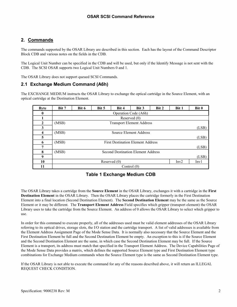
2.1 Exchange Medium Command (A6h) The EXCHANGE MEDIUM instructs the OSAR Library to exchange the optical cartridge in the Source Element, with an optical cartridge at the Destination Element.
Byte Bit 7 Bit 6 Bit 5 Bit 4 Bit 3 Bit 2 Bit 1 Bit 0 0 Operation Code (A6h) 1 Reserved (0) 2 (MSB) Transport Element Address 3 (LSB) 4 (MSB) Source Element Address 5 (LSB) 6 (MSB) First Destination Element Address 7 (LSB) 8 (MSB) Second Destination Element Address 9 (LSB)
10 Reserved (0) Inv2 Inv1 11 Control (0)
Table 1 Exchange Medium CDB The OSAR Library takes a cartridge from the Source Element in the OSAR Library, exchanges it with a cartridge in the First Destination Element in the OSAR Library. Then the OSAR Library places the cartridge formerly in the First Destination Element into a final location (Second Destination Element). The Second Destination Element may be the same as the Source Element or it may be different. The Transport Element Address Field specifies which gripper (transport element) the OSAR Library uses to take the cartridge from the Source Element. An address of 0 allows the OSAR Library to select which gripper to use. In order for this command to execute properly, all of the addresses used must be valid element addresses of the OSAR Library referring to its optical drives, storage slots, the I/O station and the cartridge transport. A list of valid addresses is available from the Element Address Assignment Page of the Mode Sense Data. It is normally also necessary that the Source Element and the First Destination Element be full and the Second Destination Element be empty. An exception to this is if the Source Element and the Second Destination Element are the same, in which case the Second Destination Element may be full. If the Source Element is a transport, its address must match that specified in the Transport Element Address. The Device Capabilities Page of the Mode Sense Data provides a matrix, which defines the supported Source Element type and First Destination Element type combinations for Exchange Medium commands when the Source Element type is the same as Second Destination Element type. If the OSAR Library is not able to execute the command for any of the reasons described above, it will return an ILLEGAL REQUEST CHECK CONDITION.
Specification: 9000238 Rev: M 2

OSAR SCSI Command Reference
The Inv1 and Inv2 bits control the inversion, or flipping, of the surfaces as cartridges go to and from the Data Transfer Elements. The Inv1 and Inv2 bits should be set to 0 because the Data Transfer elements have two heads allowing access to both sides of the medium and medium inversion is not needed. NOTE 1: The OSAR Library model 0150 has a restriction on the Inv1 and Inv2 bits. The OSAR Library can only invert an optical cartridge if it is coming from or going to an optical drive. An INVALID FIELD IN CDB CHECK CONDITION will be given if the command specifies an invert that the OSAR Library is not capable of performing. If either the source or first destination element is a data transfer element, the Inv1 bit can be set. If either the first destination or second destination element is a data transfer element, the Inv2 bit can be set. NOTE 2: The model 0155 accepts commands with invert bits of 1, but this model of the OSAR Library is not capable of inverting the optical cartridge.
Specification: 9000238 Rev: M 3

OSAR SCSI Command Reference
2.2 Initialize Element Status Command (07h) The INITIALIZE ELEMENT STATUS command will cause the OSAR Library to check all elements for an optical disk cartridge and any other status relevant to that element. The READ ELEMENT STATUS command retrieves the information generated by this command.
Byte Bit 7 Bit 6 Bit 5 Bit 4 Bit 3 Bit 2 Bit 1 Bit 0 0 Operation Code (07h) 1 Reserved (0) 2 Reserved (0) 3 Reserved (0) 4 Reserved (0) 5 Control (0)
Table 2 Initialize Element Status CDB Note: The Initialize Element Status function is done automatically by the OSAR Library when the unit is powered on or reset.
2.3 Inquiry Command (12h) The INQUIRY command requests that information regarding the target device and its attached peripheral device(s) be sent to the initiator.
Byte Bit 7 Bit 6 Bit 5 Bit 4 Bit 3 Bit 2 Bit 1 Bit 0 0 Operation Code (12h) 1 Reserved (0) EVPD 2 Page Code (00h) 3 Reserved (0) 4 Allocation Length (30h) 5 Control (0)
Table 3 Inquiry CDB Please note that the LUN may be 0 to 7. This allows the initiator to query each LUN and scan the system for devices. An EVPD bit of 0 specifies that the target shall return the standard INQUIRY data. An EVPD bit of 1 is not supported. Page Code must be set to 0, as this is the only supported Page Code. Allocation Length – The number of bytes to return to the initiator. The initiator should specify 0x30 bytes minimum. The INQUIRY command returns a CHECK CONDITION status only when the OSAR Library cannot return the requested INQUIRY data. If an INQUIRY command is received from an initiator with a pending unit attention condition (i.e. before the target reports CHECK CONDITION status), the OSAR Library shall perform the INQUIRY command and shall not clear the unit attention condition.
Specification: 9000238 Rev: M 4

OSAR SCSI Command Reference
The standard INQUIRY data (see the following table) contains the 36 required bytes plus some vendor specific data:
Byte Bit 7 Bit 6 Bit 5 Bit 4 Bit 3 Bit 2 Bit 1 Bit 0
0 Peripheral Qualifier Peripheral Device Type 1 RMB (1) Device-Type Qualifier (0) 2 ISO Version (0) ECMA Version (0) ANSI - Approved Version (2) 3 AENC (0) TrmIOP (0) Reserved (0) Response Data Format (2) 4 Additional Length (2Bh) 5 Reserved (0) 6 Reserved (0) 7 Reserved (0) 8 F (46h) 9 I (49h)
10 L (4Ch) 11 E (45h) 12 N (4Eh) 13 E (45h) 14 T (54h) 15 20h 16 (MSB) | Product Identification
19 (LSB) 20 20h | |
31 20h 32 (MSB) SCSI Firmware Revision 33 (LSB) 34 (MSB) OSAR Firmware Revision 35 (LSB) 36 20h 37 (MSB) 38 OSAR Revision Level 39 (LSB) 40 20h 41 (MSB) | OSAR Serial Number
47 (LSB)
Table 4 Inquiry Command Returned Data
Specification: 9000238 Rev: M 5

OSAR SCSI Command Reference
Peripheral Qualifier
Description
000b The specified Peripheral Device Type is currently connected to this logical unit. 011b No Device, currently connected
Table 5 Peripheral Qualifier Peripheral Qualifier – see Peripheral Qualifier Table for values.
Peripheral Device Type
Description
08h Medium Changer Device (e.g. OSAR Libraries) 1Fh No device
Table 6 Peripheral Device Type Note the Peripheral Device Type shown (08h) will be given for LUN's that have an attached OSAR Library. Not all LUN's (0 - 7) will have an attached OSAR Library. An INQUIRY command sent to a LUN that does not have an attached OSAR Library will return 7Fh for the combined Peripheral Qualifier and Device Type fields to indicate that no device exists for that LUN. A LUN that is configured but is not responding would return a 68h for the combined Peripheral Qualifier and Device Type fields. A Removable Medium Bit (RMB) of 1 indicates that the medium is removable. The ANSI-Approved Version of 2 indicates the device complies with the SCSI-2 specification. The Asynchronous Event Notification Capability (AENC) bit of 0 indicates that the device does not support the asynchronous event notification capability. A Terminate I/O Process (TrmIOP) bit of 0 indicates that the device does not support the TERMINATE I/O PROCESS message. A Response Data Format value of 2 indicates that the data shall be in the format specified in the SCSI-2 specification. The Additional Length specifies the length in bytes of the additional data to follow. This value is a constant and is not changed regardless of the length specified in the Inquiry CDB. NOTE: This device only supports 8-bit wide data transfers. The Product Identification will indicate the FileNET model number, i.e. an ASCII coded 0150 etc., as per the following table:
Product identification FileNET OSAR Library type 0150 Model 150 - GTS/HTS 0155 Model 155 - GTS/HTS
Table 7 Product Identification Field The unused bytes in the Product Identification will be set to ASCII spaces (20h) following the Product Identification. Note that the Product Identification is based on the OSAR Library model type attached as a specific LUN. If an INQUIRY is done to a LUN that does not have an OSAR Library attached, this field will be blank.
Specification: 9000238 Rev: M 6

OSAR SCSI Command Reference
The SCSI Firmware Revision is the revision level of the SCSI command interpreter subsystem. The OSAR Firmware Revision is the revision level of firmware controlling the jukebox mechanism. This value is available from the OSAR's Report Firmware Level command. The OSAR Revision Level is the revision level of the OSAR available from the OSAR’s Revision Report command. The OSAR Serial Number is the serial number of the OSAR available from the OSAR’s Serial Number Report command.
Specification: 9000238 Rev: M 7

OSAR SCSI Command Reference
2.4 I/O Station Lock Unlock Command (0Ch) The I/O STATION LOCK UNLOCK, a vendor unique command, will cause the optical library to lock or unlock the I/O Station door. This command may be sent any time the I/O Station door is closed, except the door may not be unlocked during an I/O operation or if another device has the I/O Station door reserved or has issued a Prevent Allow Medium Removal command to the library.
Byte Bit 7 Bit 6 Bit 5 Bit 4 Bit 3 Bit 2 Bit 1 Bit 0 0 Operation Code (0Ch) 1 Reserved (0) 2 Reserved (0) 3 Reserved (0) 4 Reserved (0) Open 5 Control (0)
Table 8 I/O Station Lock CDB An Open value of 1 causes the I/O Station door to unlock and a value of 0 causes the I/O Station door to lock.
2.5 Mode Select Command (15h) The MODE SELECT command allows the initiator to change the operating mode of the OSAR Library.
Byte Bit 7 Bit 6 Bit 5 Bit 4 Bit 3 Bit 2 Bit 1 Bit 0 0 Operation Code (15h) 1 Reserved (0) PF (1) Reserved (0) SP (1) 2 Reserved (0) 3 Reserved (0) 4 Allocation Length 5 Control (0)
Table 9 Mode Select CDB A Page Format (PF) bit of 1 indicates that the OSAR Library parameters following the header and block descriptors are structured as pages of related parameters and are as specified in the SCSI-2 standard. A Saved Pages (SP) bit of 0 indicates the parameters will not be saved. This mode is not supported. A bit of 1 indicates the parameters will be saved. The Allocation Length specifies the length in bytes of the mode parameter list that shall be transferred from the initiator to the target during the Data Out Phase. A parameter length of 0 indicates that no data shall be transferred; this is not considered an error.
Specification: 9000238 Rev: M 8

OSAR SCSI Command Reference
Byte Bit 7 Bit 6 Bit 5 Bit 4 Bit 3 Bit 2 Bit 1 Bit 0
0 Reserved (0) 1 Reserved (0) 2 Reserved (0) 3 Block Descriptor Length
Table 10 Mode Select Parameter List Block Descriptor Length is the number of bytes in the pages that follow.
Page Code Function Performed 20h Gripper Enable
Table 11 Mode Select Page Codes 2.5.1 Gripper Enable/Disable Page The Gripper Enable/Disable Page will control the enabling of the grippers. Since the OSAR Library contains two independent grippers, a gripper could in the event of failure be disabled and operations may continue with a single gripper.
Byte Bit 7 Bit 6 Bit 5 Bit 4 Bit 3 Bit 2 Bit 1 Bit 0 0 Reserved Page Code (20h) 1 Parameter Length (2) 2 DIS_FULL_1 ENA_1 3 DIS_FULL_2 ENA_2
Table 12 Gripper Enable/Disable Page ENA_1 is set to 1 if gripper 1 is to be enabled. ENA_1 is set to 0 if gripper 1 is to be disabled. DIS_FULL_1 is set to 0 if you wish to disable the gripper only if it is empty. DIS_FULL_1 is set to 1 if you wish to disable the gripper even if the gripper is holding a cartridge. ENA_2 is set to 1 if gripper 2 is to be enabled. ENA_2 is set to 0 if gripper 2 is to be disabled. DIS_FULL_2 is set to 0 if you wish to disable the gripper only if it is empty. DIS_FULL_2 is set to 1 if you wish to disable the gripper even if the gripper is holding a cartridge. Note: It is invalid to disable both gripper 1 and gripper 2. An attempt to disable both grippers will result in ILLEGAL REQUEST CHECK CONDITION.
Specification: 9000238 Rev: M 9

OSAR SCSI Command Reference
2.6 Mode Sense Command (1Ah) The MODE SENSE command allows the OSAR Library to report parameters to the initiator.
Byte Bit 7 Bit 6 Bit 5 Bit 4 Bit 3 Bit 2 Bit 1 Bit 0 0 Operation Code (1Ah) 1 Reserved (0) DBD (0) Reserved (0) 2 Page Control Page Code 3 Reserved (0) 4 Allocation Length 5 Control (0)
Table 13 Mode Sense CDB A Disable Block Descriptors (DBD) bit of 0 indicates that the OSAR Library may return 0 or more block descriptors in the returned MODE SENSE data, at the OSAR Library’s discretion. The Page Control defines the type of mode parameter values to be returned in the mode pages. The Page Control is defined in the following table:
Page Control Field
Type of Parameter
00b Current Values 01b Changeable Values 10b Default Values 11b Saved Values
Table 14 Page Control Field The Page Code specifies which mode pages(s) to return. The page code usage for the OSAR Library is shown in the following table:
Page Code Description Allocation Length 1Dh Element Address Assignment 24 1Eh Transport Geometry Parameters 10 1Fh Device Capabilities 24 20h Gripper Enable/Disable 8 3Fh Return All Pages 54
Table 15 Mode Page Codes Allocation Length is the maximum number of bytes to return to the initiator. An initiator may request any one or all of the supported mode pages from the OSAR Library. If an initiator issues a MODE SENSE command with a page code value not implemented by the OSAR Library, a CHECK CONDITION status with an ILLEGAL REQUEST sense key and an INVALID FIELD IN CDB additional sense code is returned. A Page Code of 3Fh indicates that all mode pages implemented by the OSAR Library shall be returned to the initiator. The Mode Pages are returned in ascending page code order.
Specification: 9000238 Rev: M 10

OSAR SCSI Command Reference
The Mode Parameter list includes the mode parameter header followed by one or more mode sense pages. The following table shows the Mode Parameter Header: 2.6.1 Mode Parameter Header
Byte Bit 7 Bit 6 Bit 5 Bit 4 Bit 3 Bit 2 Bit 1 Bit 0 0 Mode Data Length 1 Reserved (0) 2 Reserved (0) 3 Reserved (0)
Table 16 Mode Parameter Header The Mode Data Length is the total number of bytes available to be returned to the initiator. The Element Address Assignment Page is used to report addresses of the elements of the OSAR Library. This page also defines the number of each type of element present. The number of optical disk drive (data transfer) elements reported is the maximum for that model, which may be more than actually installed in the machine. The initiator can determine which data transfer elements are present by using the Read Element Status command. If both grippers are enabled, then this Element Address Assignment Page is returned.
Byte Bit 7 Bit 6 Bit 5 Bit 4 Bit 3 Bit 2 Bit 1 Bit 0 0 PS (0) Reserved (0) Page Code (1Dh) 1 Parameter Length (12h) 2 (MSB) First Medium Transport Element Address (10h)* 3 (LSB) 4 (MSB) Number of Medium Transport Elements (0002h)* 5 (LSB) 6 (MSB) First Storage Element Address (1Fh) 7 (LSB) 8 (MSB) Number of Storage Elements (see table below) 9 (LSB)
10 (MSB) First Import Export Element Address (14h) 11 (LSB) 12 (MSB) Number of Import Export Elements (0001h) 13 (LSB) 14 (MSB) First Data Transfer Element Address (0001h) 15 (LSB) 16 (MSB) Number of Data Transfer Elements (see table below) 17 (LSB) 18 Reserved (0) 19
Table 17 Element Address Assignment Page - Dual Gripper *The OSAR Library has 2 addressable medium transport elements (grippers). Each is addressable individually as element 10h or 11h, or Element Address 0 may be used in which case the OSAR Library determines which transport element to use. If a single gripper is enabled, then this Element Address Assignment Page is returned. Specification: 9000238 Rev: M 11

OSAR SCSI Command Reference
Byte Bit 7 Bit 6 Bit 5 Bit 4 Bit 3 Bit 2 Bit 1 Bit 0 0 PS (0) Reserved (0) Page Code (1Dh) 1 Parameter Length (12h) 2 (MSB) First Medium Transport Element Address (00h)* 3 (LSB) 4 (MSB) Number of Medium Transport Elements (0001h)* 5 (LSB) 6 (MSB) First Storage Element Address (1Fh) 7 (LSB) 8 (MSB) Number of Storage Elements (see table below) 9 (LSB)
10 (MSB) First Import Export Element Address (14h) 11 (LSB) 12 (MSB) Number of Import Export Elements (0001h) 13 (LSB) 14 (MSB) First Data Transfer Element Address (0001h) 15 (LSB) 16 (MSB) Number of Data Transfer Elements (see table below) 17 (LSB) 18 Reserved (0) 19
Table 18 Element Address Assignment Page - Single Gripper *With only one gripper enabled, Element Address 0 is used to address the single enabled gripper.
Model (from INQUIRY) Machine Type Number of Storage Elements
Maximum Number of Data Transfer Elements
Model 0150 107- GTS/HTS 107 6 Model 0150 123- GTS/HTS 123 4 Model 0150 144- GTS/HTS 144 2 Model 0155 40- GTS/HTS 40 3 Model 0155 50- GTS/HTS 50 2
Table 19 Number of Storage Elements and Data Transfer Elements The Transport Geometry Parameters page defines whether each Medium Transport Element is a member of a set of elements that share a common robotics subsystem and whether the element is capable of media rotation:
Byte Bit 7 Bit 6 Bit 5 Bit 4 Bit 3 Bit 2 Bit 1 Bit 0 0 PS (0) Reserved (0) Page Code (1Eh) 1 Parameter Length (4) 2 Reserved (0) Rotate (1)* 3 Member Number in Transport Element Set (0) 4 Reserved (0) Rotate (1)* 5 Member Number in Transport Element Set (1)
Table 20 Transport Geometry Parameters Page
Specification: 9000238 Rev: M 12

OSAR SCSI Command Reference
*The model 0155 accepts commands with an Invert bit of 1, but it does not rotate the media since the LD6100 optical disk drive has dual read/write heads. The Parameter Length specifies the number of bytes of transport geometry descriptors that follow. The geometry of each medium transport element is defined using a two-byte field as defined below. A Rotate bit of 1 indicates that the medium transport element supports media rotation for handling double-sided media. The Member Number in set indicates the position of this element in a set of medium transport elements that share a common robotics subsystem. The first element in a set has a member number of 0. The OSAR Library can only Rotate (Invert) a cartridge if the source or destination is a data transfer element (optical disk drive). The Rotate bit will still be set to 1 to indicate that the medium transport element is capable of doing a rotate at an optical drive elements. If a MOVE MEDIUM command or EXCHANGE MEDIUM command is given with the Invert bit set and neither the source nor the destination is an optical drive element, an ILLEGAL REQUEST CHECK CONDITION will be given. The Device Capabilities Page defines characteristics of the element types of this medium changer implementation. This information may be employed by the initiator to determine functions permitted by the MOVE MEDIUM and EXCHANGE MEDIUM commands. In the field names below, these abbreviations are used: MT - Medium Transport Element ST - Storage Element I/E - Import/Export Element DT- Data Transfer Element A StorXX bit value of 1 indicates that the defined elements of type XX may provide independent storage for a cartridge. An XX->YY bit value of 1 indicates that the medium changer device supports MOVE MEDIUM commands where the source is element type XX, the destination is element type YY, and these elements are otherwise valid. An XX<>YY bit value of 1 indicates that the medium changer device supports EXCHANGE MEDIUM commands where the source is element type XX, the first destination is element type YY, the second destination is the same type as the source element type, and these element addresses are otherwise valid.
Specification: 9000238 Rev: M 13

OSAR SCSI Command Reference
Byte Bit 7 Bit 6 Bit 5 Bit 4 Bit 3 Bit 2 Bit 1 Bit 0 0 PS (0) Reserved (0) Page Code (1Fh) 1 Parameter Length (12h) 2 Reserved (0) StorDT
(1) StorI/E
(1) StorST
(1) StorMT
(1) 3 Reserved (0) 4 Reserved (0) MT->DT
(1) MT->I/E
(1) MT->ST
(1) MT->MT
(0) 5 Reserved (0) ST->DT
(1) ST->I/E
(1) ST->ST
(1) ST->MT
(1) 6 Reserved (0) I/E->DT
(1) I/E->I/E
(1) I/E->ST
(1) I/E->MT
(1) 7 Reserved (0) DT->DT
(1) DT->I/E
(1) DT->ST
(1) DT->MT
(1) 8 - 11 Reserved (0)
12 Reserved (0) MT<>DT (1)
MT<>I/E (1)
MT<>ST (1)
MT<>MT (1)
13 Reserved (0) ST<>DT (1)
ST<>I/E (1)
ST<>ST (1)
ST<>MT (1)
14 Reserved (0) I/E<>DT (1)
I/E<>I/E (0)
I/E<>ST (1)
I/E<>MT (1)
15 Reserved (0) DT<>DT (1)
DT<>I/E (1)
DT<>ST (1)
DT<>MT (1)
16-19 Reserved (0)
Table 21 Device Capabilities Page - Dual Grippers
Byte Bit 7 Bit 6 Bit 5 Bit 4 Bit 3 Bit 2 Bit 1 Bit 0 0 PS (0) Reserved (0) Page Code (1Fh) 1 Parameter Length (12h) 2 Reserved (0) StorDT
(1) StorI/E
(1) StorST
(1) StorMT
(0) 3 Reserved (0) 4 Reserved (0) MT->DT
(1) MT->I/E
(1) MT->ST
(1) MT->MT
(0) 5 Reserved (0) ST->DT
(1) ST->I/E
(1) ST->ST
(1) ST->MT
(1) 6 Reserved (0) I/E->DT
(1) I/E->I/E
(1) I/E->ST
(1) I/E->MT
(1) 7 Reserved (0) DT->DT
(1) DT->I/E
(1) DT->ST
(1) DT->MT
(1) 8 - 11 Reserved (0)
12 Reserved (0) MT<>DT (0)
MT<>I/E (0)
MT<>ST (0)
MT<>MT (0)
13 Reserved (0) ST<>DT (1)
ST<>I/E (1)
ST<>ST (1)
ST<>MT (0)
14 Reserved (0) I/E<>DT (1)
I/E<>I/E (0)
I/E<>ST (1)
I/E<>MT (0)
15 Reserved (0) DT<>DT (1)
DT<>I/E (1)
DT<>ST (1)
DT<>MT (0)
16-19 Reserved (0)
Table 22 Device Capabilities Page - Single Gripper
Specification: 9000238 Rev: M 14

OSAR SCSI Command Reference
The Gripper Enable/Disable Page will control the enabling of the grippers. Since the OSAR Library contains two independent grippers, a gripper could in the event of failure be disabled and operations may continue with a single gripper.
Byte Bit 7 Bit 6 Bit 5 Bit 4 Bit 3 Bit 2 Bit 1 Bit 0 0 Reserved Page Code (20h) 1 Parameter Length (2) 2 DIS_FULL_1 ENA_1 3 DIS_FULL_2 ENA_2
Table 23 Gripper Enable/Disable Page ENA_1 is set to 1 if gripper 1 is enabled. ENA_1 is set to 0 if gripper 1 is disabled. DIS_FULL_1 is valid only if the ENA_1 is set to 0. DIS_FULL_1 is set to 0 if the gripper is disabled and it is required that the gripper must be empty. DIS_FULL_1 is set to 1 if the gripper is disabled even if the gripper is holding a cartridge. ENA_2 is set to 1 if gripper 2 is enabled. ENA_2 is set to 0 if gripper 2 is disabled. DIS_FULL_2 is valid only if the ENA_2 is set to 0. DIS_FULL_2 is set to 0 if the gripper is disabled and it is required that the gripper must be empty. DIS_FULL_2 is set to 1 if the gripper is disabled even if the gripper is holding a cartridge.
Specification: 9000238 Rev: M 15

OSAR SCSI Command Reference
2.7 Move Medium Command (A5h) The MOVE MEDIUM command moves an optical disk cartridge from a source element to a destination element.
Byte Bit 7 Bit 6 Bit 5 Bit 4 Bit 3 Bit 2 Bit 1 Bit 0 0 Operation Code (A5h) 1 Reserved (0) 2 (MSB) Transport Element Address 3 (LSB) 4 (MSB) Source Element Address 5 (LSB) 6 (MSB) Destination Element Address 7 (LSB) 8 Reserved (0) 9 Reserved (0)
10 Reserved (0) Invert (0) 11 Control (0)
Table 24 Move Medium CDB The Transport Element Address specifies which OSAR gripper is to be positioned. An address of 0 allows the OSAR library to select the gripper. The location that the optical disk cartridge is taken from is specified in the Source Element Address. The location that the optical disk cartridge is moved into is the Destination Element Address. If this command is received and the Source Element is empty or the Destination Element (if different from the Source Element) is full, the OSAR Library shall return CHECK CONDITION status and set the sense key to ILLEGAL REQUEST. If the address specified is not assigned to a specific element of the OSAR Library, the OSAR Library shall return a CHECK CONDITION status and set the sense key to ILLEGAL REQUEST. The device capabilities MODE SENSE page provides a matrix with the supported Source Element or Destination Element combinations for the MOVE MEDIUM command. The Invert bit should always be set to 0 because the optical disk drives have two heads allowing access to both sides of the optical disk cartridge.
Specification: 9000238 Rev: M 16

OSAR SCSI Command Reference
2.8 Position To Element command (2Bh) The POSITION TO ELEMENT command requests that the specified gripper be positioned in front of the specified destination element.
Byte Bit 7 Bit 6 Bit 5 Bit 4 Bit 3 Bit 2 Bit 1 Bit 0 0 Operation Code (2Bh) 1 Reserved (0) 2 (MSB) Transport Element Address 3 (LSB) 4 (MSB) Destination Element Address 5 (LSB) 6 Reserved (0) 7 Reserved (0) 8 Reserved (0) Invert 9 Control (0)
Table 25 Position To Element CDB The Transport Element Address specifies which OSAR gripper is to be positioned. An address of 0 allows the OSAR library to select the gripper. The Destination Element Address may represent a storage slot, the I/O station or an optical disk drive. If the address specified is not assigned to a specific element of the OSAR Library, the OSAR Library shall return CHECK CONDITION status and set the sense key to ILLEGAL REQUEST. An Invert bit of 1 specifies that the gripper mechanism be inverted or rotated prior to being positioned at the Destination Element. An Invert bit of 0 specifies that the gripper mechanism shall not be inverted or rotated prior to being positioned at the Destination Element. There is a restriction on the Invert bit. The OSAR Library can only invert the gripper mechanism if it is coming from or going to an optical disk drive. The Invert bit can be set to 1 if the destination is an optical disk drive. If the destination is not an optical disk drive the Invert bit must be 0, otherwise an ILLEGAL REQUEST CHECK CONDITION will be given. NOTE: The model 0155 accepts commands with an Invert bit of 1, but it does not rotate the optical disk cartridge.
Specification: 9000238 Rev: M 17

OSAR SCSI Command Reference
2.9 Prevent Allow Medium Removal Command (1Eh) The PREVENT ALLOW MEDIUM REMOVAL command prevents or allows the manual removal or insertion of optical disks using the I/O Station. This is done by setting a flag internally to the SCSI Translator and now allowing commands that input or output cartridges.
Byte Bit 7 Bit 6 Bit 5 Bit 4 Bit 3 Bit 2 Bit 1 Bit 0 0 Operation Code (1Eh) 1 Reserved (0) 2 Reserved (0) 3 Reserved (0) 4 Reserved (0) Prevent 5 Control (0)
Table 26 Prevent Allow Medium Removal CDB A Prevent bit of 1 prevents the removal or insertion of an optical disk cartridge using the I/O Station. A Prevent bit of 0 allows removal or insertion of an optical disk cartridge. Note: This command does not change the door lock state. Control of the door lock is done by the Lock Unlock Command.
Specification: 9000238 Rev: M 18

OSAR SCSI Command Reference
2.10 Read Element Status Command (B8h) The READ ELEMENT STATUS command causes the OSAR Library to report the status of its internal elements (storage slots, optical disk drives, I/O station and gripper mechanisms) to the initiator. See the following table for the format of the Read Element Status CDB:
Byte Bit 7 Bit 6 Bit 5 Bit 4 Bit 3 Bit 2 Bit 1 Bit 0 0 Operation Code (B8h) 1 Reserved VolTag (0) Element Type Code 2 (MSB) Starting Element Address 3 (LSB) 4 (MSB) Number of Elements 5 (LSB) 6 Reserved (0) 7 (MSB) | Allocation Length 9 (LSB)
10 Reserved (0) 11 Control (0)
Table 27 Read Element Status CDB A Volume Tag (VolTag) bit value of 0 indicates that volume tag information is not reported. The Element Type Code specifies which element type(s) to report. A value of 0 requests that status for all element types will be reported. The element type codes are defined in the following table:
Code Description 0h All Element Types Reported, (valid in CDB only) 1h Medium Transport Element 2h Storage Element 3h Import Export Element 4h Data Transfer Element
5h - Fh Reserved
Table 28 Element Type Code Starting Element Address specifies the minimum element address to report. The Number of Elements specifies the maximum number of elements to report by the OSAR Library. The value specified by this field is not the range of element addresses for reporting but rather the number of defined elements to report. If the Allocation Length is not sufficient to transfer all the element descriptors, the OSAR Library shall transfer all those descriptors that can be completely transferred. The data returned by the READ ELEMENT STATUS command consists of an eight-byte header, followed by one or more Element Status Pages.
Specification: 9000238 Rev: M 19

OSAR SCSI Command Reference
Byte Bit 7 Bit 6 Bit 5 Bit 4 Bit 3 Bit 2 Bit 1 Bit 0 0 (MSB) First Element Address Reported 1 (LSB) 2 (MSB) Number of Elements Available 3 (LSB) 4 Reserved (0) 5 (MSB) 6 Byte Count of Report Available 7 (all pages, n-7) (LSB) 8 | Element Status Page (s) n
Table 29 Read Element Status Data The First Element Address Reported is the element address of the element with the smallest element address found to meet the CDB request. The Number of Elements Available is the number of elements meeting the request in the command descriptor block. The status for these elements is returned if sufficient allocation length was specified. The Byte Count of Report Available is the number of bytes of element status page data available for all elements meeting the request in the command descriptor block. This value is not adjusted to match the allocation length available. NOTE: The READ ELEMENT STATUS command can be issued with an allocation length of eight bytes in order to determine the allocation length required to transfer all the element status data specified by the command. Each Element Status Page consists of an eight-byte header followed by one or more element descriptor blocks. The header includes the element type code, the length of each descriptor block and the number of bytes of element descriptor information that follow the header for this element type. The element status page is defined in the following table:
Byte Bit 7 Bit 6 Bit 5 Bit 4 Bit 3 Bit 2 Bit 1 Bit 0 0 Element Type Code 1 PVo1Tag (0) AVolTag (0) Reserved (0) 2 (MSB) Element Descriptor Length 3 (LSB) 4 Reserved (0) 5 (MSB) 6 Byte Count of Descriptor Data Available 7 (page, n -7) (LSB) 8 | Element Descriptor(s) n
Table 30 Element Status Page The Element Type Code indicates the element type reported by this page. A Primary Volume Tag (PVolTag) bit of 0 indicates that these bytes are omitted from the element descriptors that follow. An Alternate Volume Tag (AVolTag) bit of 0 indicates that these bytes are omitted from the element descriptors that follow. The Element Descriptor Length is the number of bytes in each element descriptor.
Specification: 9000238 Rev: M 20

OSAR SCSI Command Reference
The Byte Count of Descriptor Data Available indicates the number of bytes of element descriptor data available for elements of this element type meeting the request in the CDB. This value is not adjusted to match the allocation length available. Each Element Descriptor includes the element address and status flags; it may also contain sense code information as well as other information depending on the element type. The following table defines the medium transport element (gripper) descriptor:
Byte Bit 7 Bit 6 Bit 5 Bit 4 Bit 3 Bit 2 Bit 1 Bit 0 0 (MSB) Element Address 1 (LSB) 2 Reserved (0) Except Reserved (0) Full 3 Reserved (0)
Table 31 Medium Transport Element Descriptor The Element Address gives the address of the OSAR Library element whose status is reported by this element descriptor block. An Except bit of 1 indicates the element is in an abnormal state. An exception bit of 1 means that the gripper mechanism has been disabled either by the FE or by a Mode Select Command. An exception bit of 0 indicates the element is in a normal state. A Full bit value of 1 indicates that the element contains a cartridge. A value of 0 indicates that the element does not contain a cartridge. The following table defines the Storage Element Descriptor:
Byte Bit 7 Bit 6 Bit 5 Bit 4 Bit 3 Bit 2 Bit 1 Bit 0 0 (MSB) Element Address 1 (LSB) 2 Reserved (0) Access Except Reserved (0) Full 3 Reserved (0)
Table 32 Storage Element Descriptor An Access bit value of 1 indicates that access to the element by the transport element is allowed. An access bit of 0 indicates that access to the element by the transport element is denied. Access is denied if the element is reserved by another initiator. An Except bit of 1 indicates the element is in an abnormal state. An exception bit of 1 means that the gripper mechanism has been disabled either by the FE or by a Mode Select Command. An exception bit of 0 indicates the element is in a normal state. A Full bit value of 1 indicates that the element contains a cartridge. A value of 0 indicates that the element does not contain a cartridge. The following table defines the Import Export Element (I/O station) Descriptor:
Byte Bit 7 Bit 6 Bit 5 Bit 4 Bit 3 Bit 2 Bit 1 Bit 0 0 (MSB) Element Address 1 (LSB) 2 Reserved (0) InEnab ExEnab Access Except ImpExp Full 3 Reserved (0)
Table 33 Import/Export Element Descriptor
Specification: 9000238 Rev: M 21

OSAR SCSI Command Reference
An Import Enable (InEnab) bit of 1 indicates that the I/O station supports movement of media into the medium changer device. An InEnab bit of 0 indicates that this element does not support import action. An Export Enable (ExEnab) bit of 1 indicates that the I/O station supports movement of media out of the medium changer device. An ExEnab bit of 0 indicates that this element does not support export action. An Access bit of 1 indicates that access to the I/O station by a gripper is allowed. An access bit of 0 indicates access to the I/O station by a gripper is denied. Access is denied if the element is reserved by another initiator. NOTE: An example of when access would be denied is when the operator has exclusive access to the I/O station by having the door open. An Import Export (ImpExp) bit of 1 indicates the cartridge in the I/O station was placed there by an operator. An ImpExp bit of 0 indicates the cartridge in the I/O station was placed there by the gripper element. A Full bit value of 1 indicates that the element contains a cartridge. A value of 0 indicates that the element does not contain a cartridge. The following table defines the Data Transfer Element Descriptor:
Byte Bit 7 Bit 6 Bit 5 Bit 4 Bit 3 Bit 2 Bit 1 Bit 0 0 (MSB) Element Address 1 (LSB) 2 Reserved (0) Access Except Reserved
(0) Full
3 Reserved (0) 4 Additional Sense Code (0) 5 Additional Sense Code Qualifier (0) 6 Not Bus Reserved
(0) ID Valid LU Valid Reserved
(0) Logical Unit Number
7 SCSI Bus Address 8 Reserved (0) 9 SValid Invert Reserved (0)
10 (MSB) Source Storage Element Address 11 (LSB)
Table 34 Data Transfer Element Descriptor An Access bit value of 1 indicates access to the optical disk drive (data transfer element) by a gripper (medium transport element) is allowed. A value of 0 indicates access to the optical disk drive by a gripper is denied. Access is denied if the element is reserved by another initiator. NOTE: Access to the optical disk drive by a gripper might be denied if a data transfer operation is under way. Note that a one value in this bit may not be sufficient to ensure a successful operation. This bit can only reflect the best information available to the OSAR Library, which may not accurately reflect the state of the optical disk drive. For the OSAR Library device the access bit will also be used to handle non-contiguous data transfer elements. The data transfer element addresses may or may not have optical disk devices installed in a given machine. Access will only be allowed to a data transfer element with an access bit of 1. An ILLEGAL REQUEST CHECK CONDITION will be given for a move/exchange command to/from a data transfer element with an access bit of 0. The Additional Sense Code value of 0 indicates that there is no additional sense code information supplied. The Additional Sense Code Qualifier value 0 indicates that there is no additional sense code qualifier information supplied.
Specification: 9000238 Rev: M 22

OSAR SCSI Command Reference
A Not This Bus (Not Bus) bit value of 1 indicates that the SCSI bus address and logical unit number values are not on the SCSI bus used to select the OSAR Library. A Not Bus bit value of 0 indicates that the SCSI address and logical unit values, if valid, are on the same bus as the medium changer device. An ID Valid bit value of 1 indicates that the SCSI Bus Address contains valid information. An ID Valid bit value of 0 is used to indicate that the SCSI Bus Address does not contain valid information. An LU Valid bit of 1 indicates that the Logical Unit Number contains valid information. An LU Valid bit value of 0 is used to indicate that the Logical Unit Number does not contain valid information. The Logical Unit Number, if valid, provides the logical unit number within the SCSI bus address of the optical disk drive served by the OSAR Library at this element address. The SCSI Bus Address provides the SCSI address of the optical disk drive served by the OSAR Library at this element address. A Source Valid (SValid) bit value of 1 is used to indicate that the Source Storage Element Address and the Invert bit information are valid. A Source Valid (SValid) bit value of 0 is used to indicate that the Source Storage Element Address and the invert bit information are not valid.
Specification: 9000238 Rev: M 23

OSAR SCSI Command Reference
2.11 Release Command (17h) The RELEASE command (see table below) releases the previously reserved OSAR Library unit or elements for use by another initiator.
Byte Bit 7 Bit 6 Bit 5 Bit 4 Bit 3 Bit 2 Bit 1 Bit 0 0 Operation Code (17h) 1 Reserved (0) 3rdPty Third Party Device ID Element 2 Reservation Identification 3 Reserved (0) 4 Reserved (0) 5 Control (0)
Table 35 Release CDB The Third-Party bit (3rdPty) bit when set to 1 releases an OSAR Library unit or elements in the OSAR Library unit that were previously reserved using third party reservation by the same initiator that originally reserved it. The Third Party Device ID is the ID of the 3rd party for whom the reservation was made. The Element bit when set to 1 will cause any reservation from the requesting initiator with a matching Reservation Identification to be terminated.
2.12 Request Sense Command (03h) The REQUEST SENSE command requests that the OSAR Library transfer sense data to the initiator, see the following table:
Byte Bit 7 Bit 6 Bit 5 Bit 4 Bit 3 Bit 2 Bit 1 Bit 0 0 Operation Code (03h) 1 Reserved (0) 2 Reserved (0) 3 Reserved (0) 4 Allocation Length 5 Control (0)
Table 36 Request Sense CDB If the OSAR Library has no other sense data available to return, it shall return a sense key of NO SENSE and an additional sense code of NO ADDITIONAL SENSE INFORMATION. The Sense Data shall be preserved by the OSAR Library for the initiator until retrieved by a REQUEST SENSE command or until the receipt of any other I/O process. Sense data shall be cleared upon receipt of any subsequent I/O process (including REQUEST SENSE). The OSAR Library shall return CHECK CONDITION status for a REQUEST SENSE command only to report exception conditions specific to the command itself. For example: a) A non-0 reserved bit is detected in the command descriptor block b) An unrecovered parity error is detected on the data bus c) An OSAR Library malfunction prevents return of the sense data
Specification: 9000238 Rev: M 24

OSAR SCSI Command Reference
If a recovered error occurs during the execution of the REQUEST SENSE command, the OSAR Library shall return the sense data with GOOD status. If the OSAR Library returns CHECK CONDITION status for a REQUEST SENSE command, the sense data may be invalid. The Sense Data format for error code 70h (current errors) is defined in the following table:
Byte Bit 7 Bit 6 Bit 5 Bit 4 Bit 3 Bit 2 Bit 1 Bit 0 0 Valid Error Code (70h) 1 Segment Number (0) 2 Reserved (0) Sense Key 3 (MSB) 4 Information (0) 5 6 (LSB) 7 Additional Sense Length (n -7) 8 (MSB) 9 Command Specific Information (0)
10 11 (LSB) 12 Additional Sense Code 13 Additional Sense Code Qualifier 14 Field Replaceable Unit Code (0) 15 SKSV 16 Sense-Key Specific 17
18 - n Additional Sense Bytes
Table 37 Request Sense Data The Valid bit of 0 indicates that the Information is not valid. The Sense Key indicates generic information describing an error or exception condition. The sense keys are defined as follows.
Sense Key Name Abbr. 00 No Sense NS 01 Recovered Error RE 02 Not Ready NR 04 Hardware Error HE 05 Illegal Request IR 06 Unit Attention UA 0B Abort Command AC
Table 38 Sense Keys NOTE: ILLEGAL REQUEST CHECK CONDITION is used for commands other than INQUIRY sent to LUN's that do not have an attached OSAR Library device. The Information contains the Element Address in question on an Illegal Request during a 21h or 3Bh sense code.
Specification: 9000238 Rev: M 25

OSAR SCSI Command Reference
The following table is for Additional Sense Code and Additional Sense Code Qualifier:
Sense Key
Additional Sense Code
Additional Sense Code
Qualifier
Description
00h (NS) 00h 00h No Error Condition to Report 01h (RE) 82h 01h Command completed with backup, See Additional Sense Bytes 01h (RE) 40h 81h OSAR Fan A failed a Self-Test. Please replace the fan. 01h (RE) 40h 82h OSAR Fan B failed a Self-Test. Please replace the fan. 01h (RE) 40h 83h OSAR Fan C failed a Self-Test. Please replace the fan. 01h (RE) 40h 84h OSAR Fan D failed a Self-Test. Please replace the fan. 02h (NR) 04h 01h Logical Unit (OSAR Library) becoming ready 02h (NR) 04h 00h Logical Unit (OSAR Library) not ready. 1 02h (NR) 04h 02h Logical Unit (OSAR Library) not ready; Issue Initialize Element Status
command to clear condition 02h (NR) 05h 00h Logical Unit Not Ready, OSAR is offline 02h (NR) 08h 01h Logical Unit Not Ready, OSAR is not communicating 04h (HE) 04h 03h Logical Unit Not Ready (OSAR Fatal Error) - unit must be corrected
manually 04h (HE) 04h 88h Logical Unit Not Ready (OSAR Invalid Configuration) - unit must be
corrected manually; see Option Display data in OSAR Library 04h (HE) 15h 01h Position/Move error, See Additional Sense Bytes 04h (HE) 40h 80h Logical Unit Not Ready - failed self-test. OSAR CPU Board failed a Self-
Test 05h (IR) 1Ah 00h Parameter list length error 05h (IR) 20h 00h Invalid command operation code - non-supported Command in CDB. 05h (IR) 21h 01h Invalid element address 05h (IR) 24h 00h Invalid field in CDB 05h (IR) 25h 00h Logical Unit Not Supported 05h (IR) 26h 00h Invalid field in Parameter List 05h (IR) 3Bh 0Dh Element full 05h (IR) 3Bh 0Eh Source empty 05h (IR) 3Dh 00h Invalid bits in identify message 05h (IR) 53h 02h Medium is not allowed to leave; Prevent Allow Medium Removal Command
is active. 06h (UA) 28h 00h Not Ready to Ready Transition (Medium may have changed) 06h (UA) 3Fh 02h Changed Operating Definition 06h (UA) 29h 00h Power on, Reset, or Bus device reset occurred 0Bh(AC) 47h 00h Parity Error 0Bh(AC) 48h 00h Initiator Detected Error Message Received 0Bh(AC) 49h 00h Invalid Message Error 0Bh (AC) 4Eh 00h Overlapped Command Attempted
Table 39 Error Sense Codes
Specification: 9000238 Rev: M 26
1 This sense data (2, 4, 0) may be returned if the OSAR is reset (SCSI Bus Reset or a Device Reset Message) while performing a movement command. If a subsequent command is received while the previous movement command is being completed, check condition status will be returned with this sense key, ASL and ASCQ. Host should wait for a few seconds and then re-issue the command. If condition lasts for more than a few minutes then it should be logged, etc.

OSAR SCSI Command Reference
The Sense-Key Specific will be used for a sense key of ILLEGAL REQUEST CHECK CONDITION. The format of the Sense Key Specific for ILLEGAL REQUEST sense key is shown in the following table:
Byte Bit 7 Bit 6 Bit 5 Bit 4 Bit 3 Bit 2 Bit 1 Bit 0 15 SKSV C/D Reserved (0) BPV Bit Pointer 16 (MSB) Field Pointer 17 (LSB)
Table 40 Sense Key Data for Illegal Request The SKSV bit is set to 1 when the sense key is ILLEGAL REQUEST to indicate that the Sense Key Specific bytes (15, 16 & 17) are valid. The SKSV bit is set to 0 for other sense key conditions to indicate that the Sense Key Specific are not valid. The C/D bit is set to 1 to indicate that the error is in the command descriptor block. The C/D bit is set to 0 to indicate that the error is in the data parameters sent during the DATA OUT phase. The BPV bit is set to 1 to indicate that the Bit Pointer is valid. The BPV bit is set to 0 to indicate that the Bit Pointer is not valid. The Bit Pointer indicates which bit was in error. The Field Pointer indicates which byte in the command descriptor block or parameter data was in error. If the field that is in error is a multiple byte field, the pointer will point to the most significant byte of the field.
Specification: 9000238 Rev: M 27

OSAR SCSI Command Reference
The following is the format for Additional Sense Bytes:
Byte Bit 7 Bit 6 Bit 5 Bit 4 Bit 3 Bit 2 Bit 1 Bit 0 18 - 19 Reserved (0)
20 Field Action # 1 21 Field Action # 2 22 Field Action # 3 23 Reserved (0) 24 (MSB) Source Element Address 25 (LSB) 26 (MSB) Destination Element Address 27 (LSB) 28 (MSB) Second Destination Element Address 29 (LSB) 30 (MSB) SCSI Firmware Revision
(LSB) 32 (MSB) OSAR Firmware Revision 33 (LSB) 34 Checkpoint dump reason 35 SCSI Reset Type
36-37 OSAR Task Reset Checkpoint ID 38-39 SCSI Task Reset Checkpoint ID 40-41 OSAR Task Overlapped Command Attempted ID 42-43 SCSI Task Overlapped Command Attempted ID 44-48 Reserved (0)
49 Flash Locked
Mode 1 Mode 0 Flash Mnfr
Flash Size
SCSI ID
50 - 53 Odometer 54 Move
Cap Last SCSI
Reserved (0) Cart 10h Cart 11h Single Grip
Single Holds
55 Source Cartridge
Data Valid
Reserved (0)
Source Cart
Gripper
Source Cart
Element
Reserved (0)
56 Dest1 Cartridge
Data Valid
Reserved (0)
Dest1 Cart
Gripper
Dest1 Cart
Element
Reserved (0)
57 Dest2 Cartridge
Data Valid
Reserved (0)
Dest2 Cart
Gripper
Dest2 Cart
Element
Reserved (0)
58 Reserved (0) 59 Library Communications Log Length* 60 First Byte of Library Communications Log
(n+60)-1 Last Byte of Library Communications Log
31
Table 41 Additional Sense Bytes Format *Note: Maximum sense data length = 255 bytes where n ≤ 196 Field Action # 1 (byte 20) is the most likely Field Action that will repair the OSAR Library. The values are defined in the OSAR Maintenance Manual.
Specification: 9000238 Rev: M 28

OSAR SCSI Command Reference
Field Action # 2 (byte 21) is the 2nd most likely Field Action that will repair the OSAR Library. The values are defined in the OSAR Maintenance Manual. Field Action # 3 (byte 22) is the 3rd most likely Field Action that will repair the OSAR Library. The values are defined in the OSAR Maintenance Manual. Source Element Address (bytes 24 & 25) is the Element Address used in the Position At, Move Medium and Exchange Medium Commands. This data is a copy of the data in the CDB. Destination Element Address (bytes 26 & 27) is the Element Address used in the Move Medium and the Exchange Medium Commands. This data is a copy of the data in the CDB. Second Destination Element Address (bytes 28 & 29) is the Element Address used in the Exchange Medium Command. This data is a copy of the data in the CDB. SCSI Firmware Revision (bytes 30 & 31) The revision level of the SCSI Translator Firmware. OSAR Firmware Revision (bytes 32& 33) The revision level of the OSAR Library mechanism firmware. This is the same as the last two characters as are returned from the RZ000 OSAR Library command. Checkpoint Dump Reason (byte 34) The reason that the checkpoint data was returned. If the value is zero then the bytes 35 to 43 will be zero.
Value of Checkpoint Dump Reason: Checkpoint Dump Reason: 0x00 No checkpoint values 0x01 SCSI Bus Reset or some internal Reset happened. 0x02 An Overlapped Command Condition was attempted 0x12 A Reset condition happened followed by an Overlapped Command Condition 0x21 An Overlapped Command Condition happened followed by a Reset Condition
SCSI Reset type (byte 35) The kind of SCSI Task reset that occurred last will be encoded into this byte.
SCSI Reset Type : Reason for the Reset: 0x04 Watchdog timer went off 0x06 SCSI Bus Reset 0x0B Failure while disconnecting from the bus for a disconnect seq. 0x0C Device Reset Message Byte was received 0x0E SCSI Bus Reset 0x12 Invalid command sequence given to SCSI Controller Chip 0x16 Failure while reconnecting to the bus after disconnect 0x1D SCSI Bus Reset 0x37 Failure while reading a message byte from the host 0x3D Failure while getting data from host 0x41 Failure while sending SCSI terminate sequence (Status byte) 0x51 Failure while sending data to the host 0x55 Excessive time to send data to host
OSAR Task Reset Checkpoint ID (bytes 36 & 37) The ID of the last internal firmware checkpoint in the OSAR Task before a reset condition was encountered. SCSI Task Reset Checkpoint ID (bytes 38 & 39) The ID of the last internal firmware checkpoint in the SCSI Task before a reset condition was encountered.
Specification: 9000238 Rev: M 29

OSAR SCSI Command Reference
OSAR Task Overlapped Command Attempted Checkpoint ID (bytes 40 & 41) The ID of the last internal firmware checkpoint in the OSAR Task before an overlapped command attempt condition was encountered. SCSI Task Overlapped Command Attempted Checkpoint ID (bytes 42 & 43) The ID of the last internal firmware checkpoint in the SCSI Task before an overlapped command attempt condition was encountered. Flash Locked If 0, flash is locked; if 1 flash is write enabled. Mode 1 If 0, if directed by the host the SCSI translator will disconnect from the buss. If 1 no disconnects are allowed. Mode 0 Not used Flash Mnfr If 0 AMD flash device. If 1 Intel flash device. Flash Size If 0 then 2Mbit flash part. If 1 then 4 Mbit Flash Part. SCSI ID The SCSI Address of the OSAR Library. Odometer (bytes 50-53) is the count of the number of transactions on the OSAR Library. See the Operation Report (OR000) Command in the OSAR Maintenance Manual for more details. Mechanism State Byte (byte 54) is the status of the OSAR Library after an error. Move Cap bit of 1 indicates that the mechanism is capable of performing movement commands. A 0 indicates that it is not capable of performing movement commands. Last SCSI bit of 1 indicates the OSAR Library returned the cartridges to the state they were in before the failed command. A 0 indicates that the cartridges were not returned to the state before the failed command. Cart 10h bit of 1 indicates that a cartridge is in the transport 10h mechanism a 0 indicates that its empty. Cart 11h bit of 1 indicates that a cartridge is in the transport 11h mechanism a 0 indicates that its empty. SingleGrip is set to 0 if both grippers are operational and the Cart 10 and Cart11 bits are valid. If SingleGrip is 1 then the Cart10 and Cart11 bits are invalid. If SingleGrip is set then the SingleHolds bit is valid. SingleHolds is valid if the SingleGrip bit is set to 1. If it is valid and the single enabled gripper is holding a cartridge then it is set to 1. Source Element Byte (byte 55) indicates the status of the cartridge in the specified Source Element of the Move or Exchange command after an error. Source Cartridge Data Valid bit of 1 indicates that the values in this byte are valid. A 0 indicates that values in this byte are not valid. Source Cartridge in Gripper bit of 1 indicates that the cartridge originally in this element is in the gripper. A 0 indicates that it is not in the gripper. Source Cartridge in Element bit of 1 indicates that the cartridge being moved from this element is still in this element. A 0 indicates that the cartridge is no longer in this element. Destination 1 Element Byte (byte 56) indicates the status of the first destination element of an Exchange command or the destination element of the Move command after an error. Dest1 Cartridge Data Valid bit of 1 indicates that the values in this byte valid. A 0 indicates that the values in this byte and the element number byte are not valid. For an Exchange command: Dest1 Cartridge in Gripper bit of 1 indicates that the cartridge originally in this element is in the gripper. A 0 indicates that it is not in the gripper.
Specification: 9000238 Rev: M 30

OSAR SCSI Command Reference
Dest1 Cartridge in Element bit of 1 indicates that the cartridge being moved from this element is still in this element. A 0 indicates that the cartridge being moved from this element is no longer in this element. For a Move command: Dest1 Cartridge in Gripper bit of 1 indicates that the cartridge originally destined for this element is in the gripper. A 0 indicates that the cartridge originally destined for this element is not in the gripper. Dest1 Cartridge in Element bit of 1 indicates that the cartridge being moved to this element is in this element. A 0 indicates that the cartridge being moved to this element is not in this element. Destination 2 Element Byte (byte 57) indicates the status of the final destination element of an Exchange command after an error. Dest2 Cartridge Data Valid bit of 1 indicates that the values in this byte are valid. A 0 indicates that the values in this byte and the element number byte are not valid. Dest2 Cartridge in Gripper bit of 1 indicates that the cartridge originally destined for this element is in the gripper. A 0 indicates that the cartridge originally destined for this element is not in the gripper. Dest2 Cartridge in Element bit of 1 indicates that the cartridge being moved to this element is in this element. A 0 indicates that the cartridge being moved to this element is not in this element. Library Communications Log Length (byte 59) the length of the Library Communications Log that will be reported. Library Communications Log (bytes 60 to 255max) a dialogue of the serial communications between the SCSI Translator and the OSAR Library. This is an ASCII human readable log. Since the SCSI Translator does not include system time stamps between commands, it can be confusing when interpreting this dialog when serial commands and responses that are logged occurred during a multiple command sequence. The SCSI Translator will preserve the first failing serial command and it’s response. It will add and shift any subsequent data until the Library Communications Log is full. Therefore, the serial commands by which the SCSI Translator completed the SCSI command may not appear in the Library Communications Log portion of the SCSI Sense Data.
Specification: 9000238 Rev: M 31
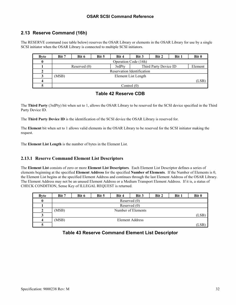
OSAR SCSI Command Reference
2.13 Reserve Command (16h) The RESERVE command (see table below) reserves the OSAR Library or elements in the OSAR Library for use by a single SCSI initiator when the OSAR Library is connected to multiple SCSI initiators.
Byte Bit 7 Bit 6 Bit 5 Bit 4 Bit 3 Bit 2 Bit 1 Bit 0 0 Operation Code (16h) 1 Reserved (0) 3rdPty Third Party Device ID Element 2 Reservation Identification 3 (MSB) Element List Length 4 (LSB) 5 Control (0)
Table 42 Reserve CDB The Third Party (3rdPty) bit when set to 1, allows the OSAR Library to be reserved for the SCSI device specified in the Third Party Device ID. The Third Party Device ID is the identification of the SCSI device the OSAR Library is reserved for. The Element bit when set to 1 allows valid elements in the OSAR Library to be reserved for the SCSI initiator making the request.
The Element List Length is the number of bytes in the Element List.
2.13.1 Reserve Command Element List Descriptors The Element List consists of zero or more Element List Descriptors. Each Element List Descriptor defines a series of elements beginning at the specified Element Address for the specified Number of Elements. If the Number of Elements is 0, the Element List begins at the specified Element Address and continues through the last Element Address of the OSAR Library. The Element Address may not be an unused Element Address or a Medium Transport Element Address. If it is, a status of CHECK CONDITION, Sense Key of ILLEGAL REQUEST is returned.
Byte Bit 7 Bit 6 Bit 5 Bit 4 Bit 3 Bit 2 Bit 1 Bit 0 0 Reserved (0) 1 Reserved (0) 2 (MSB) Number of Elements 3 (LSB) 4 (MSB) Element Address 5 (LSB)
Table 43 Reserve Command Element List Descriptor
Specification: 9000238 Rev: M 32

OSAR SCSI Command Reference
2.14 Rezero Unit Command (01h) The REZERO UNIT command causes each of the medium transport axes of motion to be driven to its respective home position. This sets the library to a defined state.
Byte Bit 7 Bit 6 Bit 5 Bit 4 Bit 3 Bit 2 Bit 1 Bit 0 0 Operation code (01h) 1 Reserved (0) 2 Reserved (0) 3 Reserved (0) 4 Reserved (0) 5 Control (0)
Table 44 Rezero Unit CDB
Specification: 9000238 Rev: M 33

OSAR SCSI Command Reference
2.15 Send Diagnostic Command (1Dh) The SEND DIAGNOSTIC command requests the OSAR Library controller to perform diagnostic operations on itself, on a specific logical unit, or on both, see the following table:
Byte Bit 7 Bit 6 Bit 5 Bit 4 Bit 3 Bit 2 Bit 1 Bit 0 0 Operation Code (1Dh) 1 Reserved (0) PF (0) Reserved (0) SelfTest DevOfL (1) UnitOfL (1)
2 Reserved (0) 3 (MSB) Parameter List Length (0004h) 4 (LSB) 5 Control Byte (0)
Table 45 Send Diagnostic CDB The PF bit of 0 indicates that the SEND DIAGNOSTIC parameters are vendor-specific. A Self-Test (SelfTest) bit of 1 directs the OSAR Library to complete its default self-test. If the self-test successfully passes, the command shall be terminated with GOOD status; otherwise, the command shall be terminated with CHECK CONDITION status and the sense key shall be set to HARDWARE ERROR. A Self-Test bit of 0 requests that the OSAR Library performs the diagnostic operation specified in the Parameter List. The Device Off-Line (DevOfL) and Unit Off-Line (UnitOfL) bits are set to 1. These bits grant permission to perform vendor-specific diagnostic operations on the OSAR Library. The Parameter List Length specifies the length in bytes of the parameter list that shall be transferred from the initiator to the OSAR Library.
Specification: 9000238 Rev: M 34

OSAR SCSI Command Reference
Byte Bit 7 Bit 6 Bit 5 Bit 4 Bit 3 Bit 2 Bit 1 Bit 0 0 Diagnostic Function Code 1 Reserved (0) 2 (MSB) Diagnostic Parameter 3 (LSB)
Table 46 Diagnostic Parameter List Format The Diagnostic Function Code is a value from 0h - 10h and selects the diagnostic function.
Function Code Function Performed 01h Electronic Self Test 02h Calibrate 03h Disable/Enable Gripper
Intentionally left blank Intentionally left blank
06h Gripper Check 07h Gripper Zee
Intentionally left blank 09h Mechanism Test 0Ah Quick Check 0Bh Range Check 0Ch Sensor Gain
Intentionally left blank 0Eh Spin Down 0Fh Spin Up 10h Test Sensors
Table 47 Send Diagnostic Function Codes The Diagnostic Parameter is a value from 0h - FFh. The meaning of the parameter is dependent on the Diagnostic Function Code as shown in the following tables:
Parameter Specific Electronic Self Test Performed 00h All of the tests 01h CPU PROM 02h CPU RAM 03h Communications Hardware 04h Real Time Clock 05h CPU Input Ports 06h CPU Output Ports 07h Non-Volatile Memory 08h Fans
Table 48 Electronic Self-Test Function Parameters Specification: 9000238 Rev: M 35

OSAR SCSI Command Reference
Parameter Specific Calibrate Performed Applicable Models 00h Entire Machine All 01h All data transfer elements All 02h Medium transport elements (grippers) All 20h Data transfer element 1 All 21h Data transfer element 2 All 22h Data transfer element 3 All 23h Data transfer element 4 0150 24h Data transfer element 5 0150 25h Data transfer element 6 0150 03h All storage elements and Import/Export element All 04h Medium transport element (gripper offset) All 30h Upper storage elements rack and Import/Export element All 31h Middle storage element rack All 32h Lower storage element rack 0150
Table 49 Calibrate Function Parameters
Parameter Specific Disable/Enable Gripper Performed 00h Enable full medium transport capability (enable both grippers) 01h Disable partial medium transport capability (disable gripper 1) 02h Disable partial medium transport capability (disable gripper 2)
Table 50 Disable/Enable Gripper Function Codes
Parameter Specific Gripper Check Performed 00h Check both grippers (both must be empty) 01h Check gripper 1 02h Check gripper 2
Table 51 Gripper Check Function Codes
Parameter Specific Gripper Zee Performed 00h Both grippers 01h Gripper 1
02h Gripper 2
Table 52 Gripper Zee Function Codes
Specification: 9000238 Rev: M 36

OSAR SCSI Command Reference
Parameter Specific Mechanism Test Performed Applicable
Models 00h Execute all test options All 01h Gripper 1 solenoid system All 02h Gripper 1 electrical operations All 03h Gripper 1 mechanical operations All 04h Gripper 2 solenoid system All 05h Gripper 2 electrical operations All 06h Gripper 2 mechanical operations All 07h Import/Export element detent solenoid system All 08h Import/Export element detent electrical operation All 09h Import/Export element detent mechanical operation All 0Ah Import/Export element door solenoid system All 0Bh Import/Export element door electrical operation All 0Ch Import/Export element door mechanical operation All 0Dh All solenoids electrical operations All 0Eh All solenoids mechanical operations All 0Fh Check all motor drive electronics All 10h Gripper 1 motor drive electronics All 11h Gripper 2 motor drive electronics All 12h Horizontal Motor Drive Electronics 0150 13h Pivot Motor Drive Electronics 0150 14h Vertical Motor Drive Electronics All
Table 53 Mechanism Test Function Codes
Parameter Specific Quick Check Performed 00h Quickly checks and adds offset to calibration data
Table 54 Quick Check Function Codes
Parameter Specific Range Check Performed Applicable Models 01h Check horizontal range 0150 02h Check vertical range All 04h Check pivot range 0150 03h Check horizontal and vertical ranges 0150 05h Check horizontal and pivot ranges 0150 06h Check vertical and pivot ranges 0150 07h Check horizontal, vertical and pivot ranges 0150
Table 55 Range Check Function Codes
Specification: 9000238 Rev: M 37

OSAR SCSI Command Reference
Parameter Specific Sensor Gain Performed Applicable Models
00h All sensors All 01h Gripper 1 - Slot Empty All 02h Gripper 2 - Slot Empty All 03h Gripper 1 - Slot Aligned All 04h Gripper 2 - Slot Aligned All
Table 56 Sensor Gain Function Codes
Parameter Specific Spin Down Performed Applicable Models 01h Spin down data transfer element 1 All 02h Spin down data transfer element 2 All 03h Spin down data transfer element 3 All 04h Spin down data transfer element 4 0150 05h Spin down data transfer element 5 0150 06h Spin down data transfer element 6 0150
Table 57 Spin Down Function Codes
Parameter Specific Spin Up Performed Applicable Models 01h Spin up data transfer element 1 All 02h Spin up data transfer element 2 All 03h Spin up data transfer element 3 All 04h Spin up data transfer element 4 0150 05h Spin up data transfer element 5 0150 06h Spin up data transfer element 6 0150
Table 58 Spin Up Function Codes
Specification: 9000238 Rev: M 38

OSAR SCSI Command Reference
Parameter Specific Test Sensor Performed Applicable Models 00h Test All Sensors All 05h Home Sensor - Horizontal Carriage 0150 06h Home Sensor - Pivot 0150 07h Home Sensor - Vertical Carriage All 08h Gripper 1 - Cart Present All 09h Gripper 2 - Cart Present All 0Ah Gripper 1 - Front Limit All 0Bh Gripper 2 - Front Limit All 0Ch Gripper 1 - Home Sensor All 0Dh Gripper 2 - Home Sensor All 0Eh Gripper 1 - Solenoid Sensor All 0Fh Gripper 2 - Solenoid Sensor All 10h Gripper 1 - Slot Aligned All 11h Gripper 2 - Slot Aligned All 12h Gripper 1 - Slot Empty All 13h Gripper 2 - Slot Empty All 14h Import/Export Element - Cart Fully Inserted All 15h Import/Export Element - Cart Orientation Invalid All 16h Import/Export Element - Cart Present All 17h Import/Export Element - Detent Solenoid All 18h Import/Export Element - Door Lock Solenoid All 19h Import/Export Element - Door Closed All 32h Carts Out Of Place - Rack 0 (Upper) All 33h Carts Out Of Place - Rack 1 (Lower) All 34h Carts Out Of Place - Rack 2 0150
Table 59 Test Sensors Function Codes
2.16 Test Unit Ready Command (00h) The TEST UNIT READY command provides a means to check if the logical unit is ready. If the logical unit would accept an appropriate medium-access command without returning CHECK CONDITION status, this command shall return a GOOD status. If the logical unit is not operational, the OSAR Library returns CHECK CONDITION status with a sense key of NOT READY. See the following table for the format of the Test Unit Ready CDB:
Byte Bit 7 Bit 6 Bit 5 Bit 4 Bit 3 Bit 2 Bit 1 Bit 0 0 Operation code (00h) 1 Reserved (0) 2 Reserved (0) 3 Reserved (0) 4 Reserved (0) 5 Control (0)
Table 60 Test Unit Ready CDB
Specification: 9000238 Rev: M 39

OSAR SCSI Command Reference
3. Messages
Message Name Direction 00 Command Complete In 01 Extended Message Request Out 02 Save Data Pointer In 04 Disconnect In 05 Initiator Detected Error Out 06 Abort Out 07 Message Reject In/Out 08 No Operation Out 09 Message Parity Error Out 0C Bus Device Reset Out
80-FF Identify In/Out
Table 61 SCSI Target Adapter Message Codes It is a requirement for the Initiator to support disconnection and reselection in order to use the OSAR Target Device effectively. All commands that support disconnect should be issued with Bit 6 set in the Identify Message Out. This is important in order to allow other SCSI ID optical disk devices and other LUN OSAR devices to get access to the SCSI Bus. The OSAR Library commands may take several seconds and it is undesirable to tie up the SCSI bus for that long.
4. Disconnects The following commands do not support disconnect, see table below.
Code (Hex) Command 00H Test Unit Ready 03H Request Sense 12H Inquiry 15H Mode Select 16H Reserve 17H Release 1Ah Mode Sense 1EH Prevent Allow Medium Removal B8H Read Element Status
Table 62 Commands That Do Not Disconnect
Specification: 9000238 Rev: M 40

OSAR SCSI Command Reference
Specification: 9000238 Rev: M 41
5. Status Code Name
00 Good 02 Check Condition 08 Busy 18 Reservation Conflict
Table 63 SCSI Target Adapter Status Codes
The OSAR SCSI Target device will accept one command for each LUN. If a command is issued from a different initiator to a LUN that already has a command pending, a Busy Status will be issued.