oshpd special seismic certification preapproval (osp) tested units in osp and for installations...
TRANSCRIPT

OFFICE OF STATEWIDE HEALTH PLANNING AND DEVELOPMENT FACILITIES DEVELOPMENT DIVISION
“Access to Safe, Quality Healthcare Environments that Meet California’s
STATE OF CALIFORNIA – HEALTH AND HUMAN SERVICES AGENCY OSH-FD-759 (REV 12/16/15) Page 1 of 3
APPLICATION FOR OSHPD SPECIAL SEISMIC CERTIFICATION PREAPPROVAL (OSP)
OFFICE USE ONLY
APPLICATION #: OSP – 0207 – 10
OSHPD Special Seismic Certification Preapproval (OSP)
Type: New Renewal
Manufacturer Information
Manufacturer: Ascom Wireless Solutions
Manufacturer’s Technical Representative: Michael Potvin
Mailing Address: 9024 Town Center Parkway, Suite 100, Bradenton, FL 34202
Telephone: 941-724-8200 Email: [email protected]
Product Information
Product Name: Telligence
Product Type: Nurse Call System
Product Model Number: See attached Ascom Seismic Products OSHPD (List all unique product identification numbers and/or part numbers)
General Description: The Telligence system patient-staff communications network is a distributed network-centric,
Internet protocol-based architecture system. Approval is limited to maximum C.G. and weights, listed within tested units in OSP and for installations within wall or floor mounted racks, as listed at the end of OSP.
Mounting Description: Units mounted, within both floor and wall racks, rigidly to structure.
Applicant Information
Applicant Company Name: Ascom Wireless Solutions
Contact Person: Michael Potvin
Mailing Address: 9024 Town Center Parkway, Suite 100, Bradenton, FL 34202
Telephone: 941-724-8200 Email: [email protected] I hereby agree to reimburse the Office of Statewide Health Planning and Development review fees in accordance with the California Administrative Code, 2016. Signature of Applicant: Date: 5/10/2019 Title: Regulatory Affairs Engineer Company Name: Ascom Wireless Solutions
OSP-0207-10
Timothy J. Piland
08/26/2019
08/26/2019
OSP-0207-10
Page 1 of 15

OFFICE OF STATEWIDE HEALTH PLANNING AND DEVELOPMENT FACILITIES DEVELOPMENT DIVISION
“Access to Safe, Quality Healthcare Environments that Meet California’s
California Licensed Structural Engineer Responsible for the Engineering and Test Report(s)
Company Name: MRH Structural Engineers, Inc.
Name: Mohammad R. Hariri California License Number: 3545
Mailing Address: 3400 Irvine Ave., Suite 101, Newport, CA 92660
Telephone: 714-633-6302 Email: [email protected]
Supports and Attachments Preapproval
Supports and attachments are preapproved under OPM- 0249-13 (Two-Post Floor Rack: Model 1385Y-X03) 0196-13 (Wall-Rack: Model 11840-X24) 0196-13 (Wall-Rack: Model 11890-X24)
(Separate application for OSHPD Preapproval of Manufacturer’s Certification (OPM) of Supports and attachments is required)
Supports and attachments are not preapproved
Certification Method
Testing in accordance with: ICC-ES AC156
Other (Please Specify):
Testing Laboratory
Company Name: Applied Technical Services, Inc.
Contact Name: David Common
Mailing Address: 1049 Triad Court, Marietta, Georgia 30062
Telephone: 770-423-1400 Email: [email protected]
STATE OF CALIFORNIA – HEALTH AND HUMAN SERVICES AGENCY OSH-FD-759 (REV 12/16/15) Page 2 of 3
OSP-0207-10
Timothy J. Piland
08/26/2019
08/26/2019
OSP-0207-10
Page 2 of 15

OFFICE OF STATEWIDE HEALTH PLANNING AND DEVELOPMENT FACILITIES DEVELOPMENT DIVISION
“Access to Safe, Quality Healthcare Environments that Meet California’s
STATE OF CALIFORNIA – HEALTH AND HUMAN SERVICES AGENCY OSH-FD-759 (REV 12/16/15) Page 3 of 3
Seismic Parameters
Design in accordance with ASCE 7-10 Chapter 13: Yes No
Design Basis of Equipment or Components (Fp/Wp) = 1.70
SDS (Design spectral response acceleration at short period, g) = 2.27
ap (In-structure equipment or component amplification factor) = 2.5
Rp (Equipment or component response modification factor) = 6.0
Ω0 (System overstrength factor) = 2.0
Ip (Importance factor) = 1.5
z/h (Height factor ratio) = 1
Equipment or Component Natural Frequencies (Hz) = See attachment
Overall dimensions and weight (or range thereof) = See attachment
Equipment or Components @ grade designed in accordance with ASCE 7-10 Chapter 15: Yes No
Design Basis of Equipment or Components (V/W) =
SDS (Design spectral response acceleration at short period, g) =
SD1 (Design spectral response acceleration at 1 second period, g) =
R (Response modification coefficient ) =
Ω0 (System overstrength factor) =
Cd (Deflection amplification factor) =
Ip (Importance factor) = 1.5
Height to Center of Gravity above base =
Equipment or Component Natural Frequencies (Hz) =
Overall dimensions and weight (or range thereof) =
Tank(s) designed in accordance with ASME BPVC, 2015: Yes No
List of Attachments Supporting Special Seismic Certification
Test Report(s) Drawings Calculations Manufacturer’s Catalog
Other(s) (Please Specify):
OSHPD Approval (For Office Use Only) – Approval Expires on December 31, 2022
Signature: Date: August 26, 2019
Print Name: Timothy J. Piland Title: SSE
Special Seismic Certification Valid Up to : SDS (g) = 2.27 z/h = 1
Condition of Approval (if applicable):
Approval is limited to maximum C.G. and weights, listed within tested units in OSP and for installations within wall or floor mounted racks, as listed at the end of OSP.
OSP-0207-10
Timothy J. Piland
08/26/2019
08/26/2019
OSP-0207-10
Page 3 of 15

Floor-Mounted Racks
Subcomponents Manufacturer Part # Max. Loaded Weight (lbs)
SDS Fp/Wp Testing Status
Seismic Frame Two-Post Rack Chatsworth Products, Inc. (CPI) 13853-703 836 2.27 1.70 NTS Rpt. PR033240 ENV 1
Power Switch Ascom HC-IPSWITCH8 2.27 1.70 NTS Rpt. PR033240 ENV 1 Station Gateway Ascom NGGTWY2-H 2.27 1.70 NTS Rpt. PR033240 ENV 1 Smart-UPS 1500 VA APC SMT1500RM2UC 2.27 1.70 NTS Rpt. PR033240 ENV 1
Equipment Tie-Down Bracket Chatsworth Products, Inc. (CPI) 11349-19
2.27 1.70 NTS Rpt. PR033240 ENV 1
20-Outlet Surge Power Strip Chatsworth Products, Inc. (CPI) 12851-02
2.27 1.70 NTS Rpt. PR033240 ENV 1
Wall-Mounted Racks
Subcomponents Manufacturer Part # Max.
Weight (lbs)
SDS Fp/Wp Testing Status
CUBE-iT Plus 24"Wx24"Hx24"D rack Chatsworth Products, Inc. (CPI)
11840-724 139 2.27 1.70 NTS Rpt. PR033240 ENV 3
Power Switch Ascom HC-IPSWITCH8 2.27 1.70 NTS Rpt. PR033240 ENV 3 Station Gateway Ascom NGGTWY2-H 2.27 1.70 NTS Rpt. PR033240 ENV 3 Smart-UPS 1500 VA APC SMT1500RM2UC 2.27 1.70 NTS Rpt. PR033240 ENV 3
Equipment Tie-Down Bracket Chatsworth Products, Inc. (CPI) 11349-19
2.27 1.70 NTS Rpt. PR033240 ENV 3
Horiz. Cable Management Bar Chatsworth Products, Inc. (CPI) 11837-01
2.27 1.70 NTS Rpt. PR033240 ENV 3
12-RMU Mounting Rails Chatsworth Products, Inc. (CPI) 12787-524
2.27 1.70 NTS Rpt. PR033240 ENV 3
8-Outlet 15A Surge Power Strip Chatsworth Products, Inc. (CPI) 12848-02
2.27 1.70 NTS Rpt. PR033240 ENV 3
CUBE-iT Plus 24"Wx24"Hx18"D rack Chatsworth Products, Inc. (CPI) 11890-724 151 2.27 1.70 ATS Rpt. 309082 ENV2
Station Gateway Ascom NGGTWY2-H 2.27 1.70 ATS Rpt. 309082 ENV2 Power Switch Ascom HC-IPSWITCH8 2.27 1.70 ATS Rpt. 309082 ENV2 Smart-UPS SC 450VA APC SC450RM1UC 2.27 1.70 ATS Rpt. 309082 ENV2
PoE Switch Cisco WS-3560CX-8PC-S
2.27 1.70 ATS Rpt. 309082 ENV2
8-Outlet 15A Surge Power Strip Chatsworth Products, Inc. (CPI) 12820-701
2.27 1.70 ATS Rpt. 309082 ENV2
Ascom - Telligence Patient-Staff Communication Systems
OSP-0207-10
Timothy J. Piland
08/26/2019
08/26/2019
OSP-0207-10
Page 4 of 15

Ascom Telligence Patient -Staff Communication Systems
Floor-Mounted Racks
Sub- Components Manufacturer Part# Max. Loaded Weights(lbs) SDS Fp/Wp Testing Status
Seismic Frame Two-Post Rack Chatsworth Products 13853-703 836 2.27 1.70 NTS Rpt. PR033240 ENV1 Power Switch Ascom HC-IPSWITCH8 2.27 1.70 NTS Rpt. PR033240 ENV1 Station Gateway Ascom NGGTWY2-H 2.27 1.70 NTS Rpt. PR033240 ENV1 Smart-UPS 1500VA APC SMT1500RM2UC 2.27 1.70 NTS Rpt. PR033240 ENV1 Equipment Tie-Down Bracket Chatsworth Products 11349-19 2.27 1.70 NTS Rpt. PR033240 ENV1 20-Outlet Surge Power Strip Chatsworth Products 12851-02 2.27 1.70 NTS Rpt. PR033240 ENV1 Test Report PR033240 Rev. 1 – ENV 1
Ascom Telligence Nurse Call System, floor-mounted rack Chatsworth Products, Inc. Seismic Frame 13853-703 Two-Post Rack: 24”W x 15”D x 84”H Weight: 836 lbs, including 711 lbs added weight See following page for loading configuration Floor Mounted with (4) – ½” bolts, Grade 8, 2” sq. X 3/8” (A36) plate washer atop a 3.75”sg. X 3/8” (ASTM 1018, 20KSI) plate washer.
Building Code
Test Criteria
SDS
(g) z/h Horizontal Vertical
AFLX-H ARIG-H AFLX-V ARIG-V
CBC 2016 ICC-ES AC 156 2.27 1 3.63 2.72 1.51 0.61
Natural Frequencies Test Results F-B S-S V The UUT maintained structural integrity and functionality
after the AC156 test. Unit full of contents. 9.5 Hz 6.8 Hz > 33 Hz
OSP-0207-10
Timothy J. Piland
08/26/2019
08/26/2019
OSP-0207-10
Page 5 of 15

Test Configuration – ENV 1
Center of gravity is approximately located at 38” from the base. Certified Components are to be positioned as shown.
OSP-0207-10
Timothy J. Piland
08/26/2019
08/26/2019
OSP-0207-10
Page 6 of 15

US & Canada+1-800-834-4969Toronto, Ontario, Canada+905-850-7770chatsworth.com
Latin America +52-55-5203-7525Toll Free within Mexico01-800-01-7592chatsworth.com.co
Europe+44-1628-524-834chatsworthproducts.co.uk
Middle East & AfricaDubai, UAE+971-4-2602125chatsworth.ae
Asia Pacific+86 21 6880-0266chatsworth.com.cn
Protecting your technology investment.PRODUCT DATA SHEET
Availability: Global
Support rack-mount network
equipment in data centers
and premise networks where
seismic activity exists.
KEY FEATURES
• Welded, steel network equipment rack engineered specifically to protect equipment in areas with seismic activity
• Independently seismic-tested and certified; meets industry-recognized Telcordia® Technologies, Inc. GR-63-CORE Network Equipment Building Systems (NEBS) Zone 4 requirements
• 1,000 lb (453.6 kg) load rating for seismic areas
• Supports 19” EIA-310-D compliant rack-mount equipment like patch panels and network switches; 23” W version also available
• 19” W rack fits within a 24” (610 mm) raised access floor tile
• Available with #12-24 threaded or square-punched adjustable-depth equipment mounting rails
• Equipment mounting rails have marked and numbered rack-mount spaces (U); numbering can start at the top or bottom of the rack
• Fully bonded rack has two masked grounding locations and includes a Two Mounting Hole Ground Terminal Block for easy connection to the Telecommunications Grounding Busbar
• Vertical Power Strips and T-shaped Cable Management Fingers attach directly to the rack channel to provide power and cable distribution for equipment
SPECIFICATIONS
Includes
Welded, steel frameEquipment mounting rails, two pairs50 each equipment mounting screws/cage nuts1 each Two Mounting Hole Ground Terminal Block
Available SizesHeight: 7’ (2.1 m)Widths: 24” (610 mm) and 28” (710 mm)Depth: 15” (380 mm) at base; 9.6” (244 mm) vertical channels
Equipment SpaceHeight: 44UWidth: 19” EIA or 23”Rail depths: 6” (150 mm) or 3” (80 mm)
Equipment Support
Two pairs of L-shaped equipment mounting rails fixed in place at 6”D (150 mm) or 3”D (80 mm)19” W EIA-310-D compliant or 23” WUniversal Hole Pattern, 5/8”-5/8”-1/2” alternating vertical mounting hole spacingThreaded #12-24 or square-punched equipment mounting holesIncludes 50 each mounting screws or cage nuts and mounting screws
Load Capacity 1000 lb (453.6 kg) of equipment in seismic areas
Bonding and Grounding
Rack components are bonded through weldsMounting rails are bonded to the rack through attachment hardware; optional zinc-plated mounting rails provide direct metal contact with rack-mount equipmentIncludes two masked ground connection points located at the top and base of the rackIncludes one Two Mounting Hole Ground Terminal; Block for connection to the Telecommunications; Grounding Busbar
Adjustable Depth Mounting RailsSet 6” (150 mm) or 3” (80 mm) apart
ADVANTAGES
Cable Management Built-in locations on rack
Two Mounting Hole Ground Terminal BlockIncluded for easy connection to the Telecommunications Grounding Busbar
SeismicFrame® Two-Post RackCaliforniaOSHPD
OPM-0112-13
For Refe
rence
Only
OSP-0207-10
Timothy J. Piland
08/26/2019
08/26/2019
OSP-0207-10
Page 7 of 15

PRODUCT DATA SHEET
2 Chatsworth Products
Design FeaturesCPI’s SeismicFrame® Two-Post Rack is designed specifically to support network equipment in areas with seismic activity. When earthquakes occur, equipment racks move back-and-forth with the building causing violent vibration through racks and equipment. An earthquake can easily damage or destroy non-seismic racks and equipment that are not carefully braced. The welded, steel SeismicFrame Two-Post Rack resists the swaying motion caused by earthquakes to reduce the amount of vibration transferred through the rack to equipment and is less likely to be damaged during a seismic event, which means faster network recovery.
The SeismicFrame Two-Post Rack supports 19” W EIA-310-D compliant or 23” W equipment with two pairs of mounting rails that can be spaced 6” (150 mm) or 3” (80 mm) apart. The mounting rails are marked and numbered with rack-mount spaces (U) and can be attached so that numbering starts at the bottom or top of the rack mount space. Choose threaded or square-punched mounting rails with a painted or zinc-plated finish. The mounting holes in threaded mounting rails are tapped with #12-24 threads to speed installation of panel-mount equipment with #12-24 screws. The square-punched rails accept cage nut hardware allowing you to change threads at each U to match equipment mounting requirements. CPI’s SeismicFrame Two-Post Rack ships fully assembled and includes a Two Mounting Hole Ground Terminal Block for bonding the rack to the Telecommunications Grounding Busbar and 50 each equipment mounting screws or cage nuts and screws. The rack is rated for a 1000 lb (453.6 kg) seismic Zone 4 load per Section 4.4 of the Telcordia® Technologies, Inc. GR-63-CORE Network Equipment Building Systems (NEBS) requirements.
See reverse for product details. Contact CPI Technical Support, or visit the CPI website (www.chatsworth.com/seismic) for configuration assistance.
DIMENSIONS
USE WITH
• SeismicFrame Two-Post Rack Vertical Cabling Section
• Top-Mount Cable Waterfall Tray
• Cable Management Fingers Kit
• SeismicFrame Two-Post Rack Concrete Floor Anchor Kit
SeismicFrame® Two-Post Rack
Certifications:
EIA-310-D compliant; UL Listed NWIN per UL 60950, File E227626OSHPD OPM-0249-13, California, Office of Statewide Health Planning and Development (OSHPD), Preapproval of Manufacturer's Certification (OPM)GR-63-CORE, NEBS, Zone 4US Patent Number: 8,424,691
Material Steel
ConstructionWeldedMounting rails attach with hardware
FinishEpoxy-polyester hybrid powder coat paint in black, gray or computer beigeMounting rails are painted or zinc-plated
Installation
Each rack must be secured to the structural floorOrder a seismic-rated, concrete anchor kit separatelyUse M12 x 5-1/8” Hilti HSL-3-G Heavy Duty Sleeve Anchors or equivalentWhen bayed in a continuous row, the spacing between racks should be determined by a licensed structural engineer familiar with seismic applications and codes. Each installation requirement varies.
Minimum recommended thickness of the concrete slab on the ground floor is 5-1/2” (140 mm)
Environment For indoor use only, in environmentally controlled areas; may not be used outdoors, in industrial or harsh environments, or in plenum spaces
RELATED PRODUCTS
• Heavy Duty Equipment Shelf for 6” (150 mm) Channel
• Vertical Cabling Section Offset Mounting Bracket Kit for Single-Sided Wide Vertical Cabling Section
• 3” (80 mm) Channel Rack-To-Runway Mounting Plate
• Cable Runway J-Bolt Kit
Description 19 in (mm) 23 in (mm)
Overall Width (A) 24.0 (610) 28.0 (710)
Frame Opening (B) 19.3 (490) 23.3 (592)
Rail Clearance (C) 17.75 (450) 21.75 (552)
A
B
C
15.0"(380 mm)
9.6"(294 mm)
For Refe
rence
Only
OSP-0207-10
Timothy J. Piland
08/26/2019
08/26/2019
OSP-0207-10
Page 8 of 15

PRODUCT DATA SHEET
3 Chatsworth Products
SeismicFrame® Two-Post Rack
PartNumber
DescriptionH x Wft (m)
Shipping Weightlb (kg)
13853-X03 7 (2.1) x 19”, 44U, Tapped #12-24 Zinc Rails 180 (81.6)
13854-X03 7 (2.1) x 19”, 44U, Square-Punched Zinc Rails 178 (80.7)
13855-X03 7 (2.1) x 19”, 44U, Tapped #12-24 Painted Rails 180 (81.6)
13856-X03 7 (2.1) x 19”, 44U, Square-Punched Painted Rails 178 (80.7)
13883-X03 7 (2.1) x 23”, 44U, Tapped #12-24 Zinc Rails 185 (83.9)
13884-X03 7 (2.1) x 23”, 44U, Square-Punched Zinc Rails 183 (83.0)
13885-X03 7 (2.1) x 23”, 44U, Tapped #12-24 Painted Rails 185 (83.9)
13886-X03 7 (2.1) x 23”, 44U, Square-Punched Painted Rails 183 (83.0)
ORDERING INFORMATION
Notes: X=color; 1=Gray, 2=Computer Beige, 7=Black. Install using (4) seismic-rated concrete anchors (sold separately).
Cable Management: - The top of the rack is punched with attachment points for the CPI Top-Mount Cable Waterfall Tray and
Cable Runway - Attach 9” W (230 mm), 12” W (300 mm), 15” W (380 mm) and 18” W (460 mm) Cable Runway to racks in
perpendicular (front-to-back) orientation with the Cable Runway J-Bolt Kit; 23” W racks will also support 20” W (510 mm) Cable Runway
- Attach 12” W (300 mm) to 24” W (610 mm) Cable Runway in parallel (side-to-side) orientation with the 3” W (80 mm) Channel Rack-To-Runway Mounting Plate.
- The front of the rack is punched with attachment points for the CPI Cable Management Fingers Kits - The sides of the rack are punched with three pairs of centered, 1/2-20 threaded attachment points for CPI
SeismicFrame Two-Post Rack Vertical Cabling Section - Attach a CPI Single-Sided Wide Vertical Cabling Section to the side of the rack with the CPI Vertical
Cabling Section Offset Mounting Bracket Kit - Evolution® Cable Management and MCS-EFX Master Cabling Section with Extended Fingers will also
attach to the side of the rack Shelves: - Use CPI Heavy Duty Equipment Shelf for 6” (150 mm) Channel with the rack’s mounting rails set 6” (150
mm) apart - When rails are set 3” W (80 mm) apart, the maximum shelf width on 19” W racks is 19.3” W (490 mm)
and the maximum shelf width on 23” W racks is 23.3” W (592 mm)
SeismicFrame® Two-Post Rack
ACCESSORIES
SeismicFrame® Two-Post Rack Accessories
PartNumber Description
Shipping Weightlb (kg)
13704-X03 VCS Vertical Cabling Section 35 (15.9)
13696-001 Cable Management Fingers Kit, Single-Sided, Black 7 (3.2)
13696-002 Cable Management Fingers Kit, Double-Sided, Black 14 (6.4)
13699-701 VCS Offset Mounting Bracket Kit, Black 2 (0.9)
SeismicFrame Two-Post RackVertical Cabling SectionProvide a double-sided, front and rear cable pathway next to SeismicFrame Two-Post Rack.• Separate front and rear 6”W x 6.38”D (150 mm x
162 mm) cable managers attach with included offset brackets to align with the front and rear of the rack
• Large cable pass-through ports on the back of each manager align with ports in the side of the frame; spin-open plastic latches secure cables inside the managers
• Includes one Single-Sided Cable Management Fingers Kit to organize cables by U
• Made of aluminum• Includes installation hardware
Cable Management Fingers KitOrganize patch cords and jumper cables by U.• 7U T-shaped plastic cable guides snap onto the front
and rear of the rack frame• Openings between the T-shaped guides align with each
U on the rack• Single-Sided Kit includes 12 cable guides for one side
(front or rear) of the rack• Double-Sided Kit includes 24 cable guides for both
sides (front and rear) of the rack
Notes: X=color; 1=Gray, 2=Computer Beige, 7=Black.
Vertical Cabling Section (VCS) Offset Mounting Bracket KitAttach a CPI Single-Sided Wide Vertical Cabling Section to the side of the SeismicFrame Two-Post Rack so that it aligns with the front of the rack.• Kit includes four Offset Mounting Brackets• Use two brackets per side to attach the Vertical
Cabling Section• Brackets are slotted allowing front-to-rear adjustment• Made of steel
For Refe
rence
Only
OSP-0207-10
Timothy J. Piland
08/26/2019
08/26/2019
OSP-0207-10
Page 9 of 15
PRODUCT DATA SHEET
Interested in learning more about our Cable Managers? Call us at 800-834-4969,
or email Technical Support at [email protected].
CPI now offers Extended Limited Warranties on CPI-Branded Electronic products, available for two additional years beyond the expiration of the Original Warranty Period (3 years).
Contact CPI Customer Service, or visit www.chatsworth.com/warranty for moreinformation.
While every effort has been made to ensure the accuracy of all information, CPI does not accept liability for any errors or omissions and reserves the right to change information and descriptions of listed services and products.
©2017 Chatsworth Products, Inc. All rights reserved. Chatsworth Products, CPI, CPI Passive Cooling, eConnect, RMR, MegaFrame, Saf-T-Grip, SeismicFrame, SlimFrame, TeraFrame, GlobalFrame, CUBE-iT PLUS, Evolution, OnTrac, QuadraRack and Velocity are
federally registered trademarks of Chatsworth Products. Simply Efficient, Secure Array, EuroFrame, Clik-Nut and Motive are trademarks of Chatsworth Products. All other trademarks belong to their respective companies. Rev.8 04/17 MKT-60020-402
SeismicFrame® Two-Post Rack
ACCESSORIES
SeismicFrame® Two-Post Rack Accessories
PartNumber Description
Shipping Weightlb (kg)
13697-001 Vertical Power Strip Mounting Kit, Clear 1 (0.5)
13698-001 Duplex Electrical Outlet Box, Zinc 1 (0.5)
13702-001 Concrete Floor Anchor Kit, Zinc-Plated 3 (1.4)
13703-701 Floor Drilling Template, Black 6 (2.7)
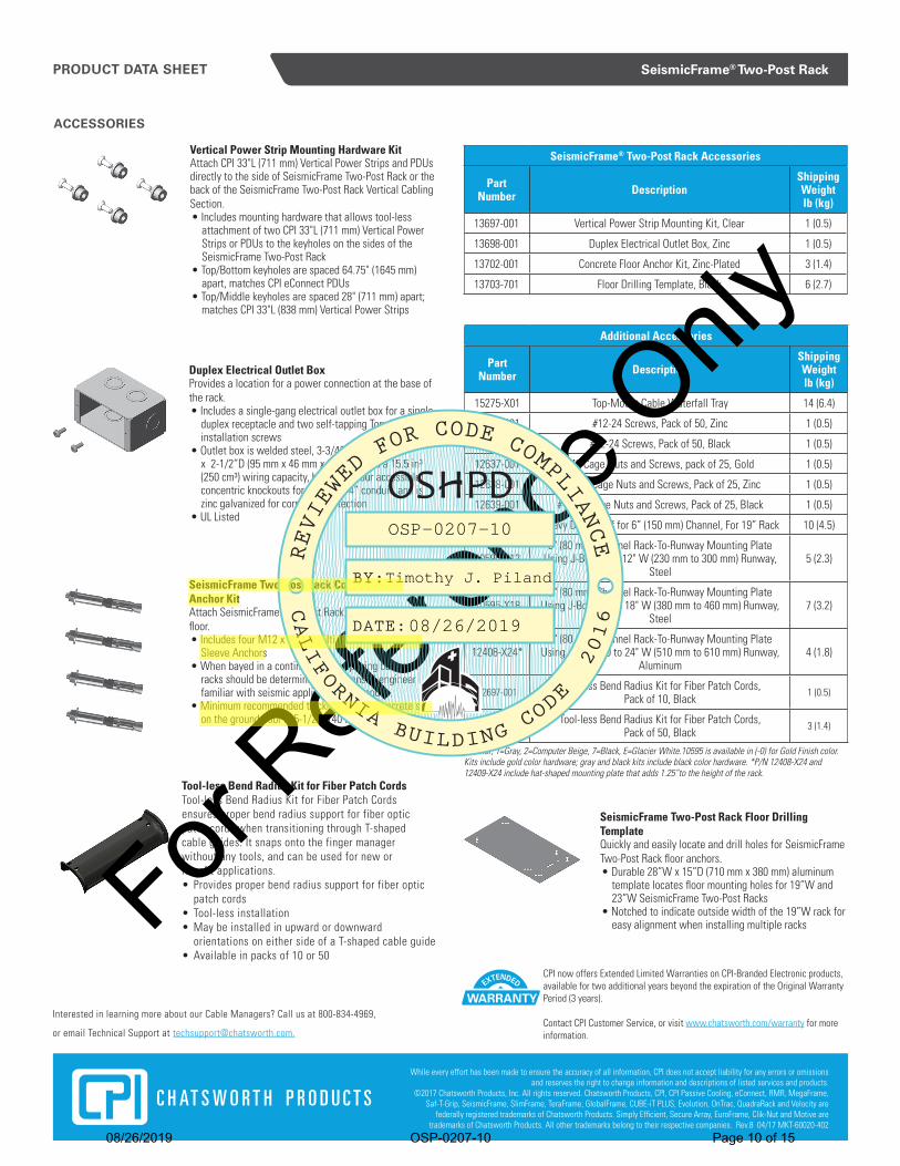
Vertical Power Strip Mounting Hardware KitAttach CPI 33"L (711 mm) Vertical Power Strips and PDUs directly to the side of SeismicFrame Two-Post Rack or the back of the SeismicFrame Two-Post Rack Vertical Cabling Section.• Includes mounting hardware that allows tool-less
attachment of two CPI 33"L (711 mm) Vertical Power Strips or PDUs to the keyholes on the sides of the SeismicFrame Two-Post Rack
• Top/Bottom keyholes are spaced 64.75" (1645 mm) apart, matches CPI eConnect PDUs
• Top/Middle keyholes are spaced 28" (711 mm) apart; matches CPI 33"L (838 mm) Vertical Power Strips
Duplex Electrical Outlet BoxProvides a location for a power connection at the base of the rack.• Includes a single-gang electrical outlet box for a single
duplex receptacle and two self-tapping Torx head T25 installation screws
• Outlet box is welded steel, 3-3/4”H x 1-13/16”W x 2-1/2”D (95 mm x 46 mm x 64 mm) with a 15.5 in³ (250 cm³) wiring capacity, has eight (four accessible) concentric knockouts for 1/2” or 3/4” conduit, and is zinc galvanized for corrosion protection
• UL Listed
SeismicFrame Two-Post Rack Concrete Floor Anchor KitAttach SeismicFrame Two-Post Rack to a concrete slab floor.• Includes four M12 x 5-1/8” Hilti HSL-3-G Heavy Duty
Sleeve Anchors• When bayed in a continuous row, spacing between
racks should be determined by a licensed engineer familiar with seismic applications and codes.
• Minimum recommended thickness of the concrete slab on the ground floor is 5-1/2” (140 mm)
SeismicFrame Two-Post Rack Floor Drilling TemplateQuickly and easily locate and drill holes for SeismicFrame Two-Post Rack floor anchors.• Durable 28”W x 15”D (710 mm x 380 mm) aluminum
template locates floor mounting holes for 19”W and 23”W SeismicFrame Two-Post Racks
• Notched to indicate outside width of the 19”W rack for easy alignment when installing multiple racks
Additional Accessories
PartNumber Description
Shipping Weightlb (kg)
15275-X01 Top-Mount Cable Waterfall Tray 14 (6.4)
40605-001 #12-24 Screws, Pack of 50, Zinc 1 (0.5)
40605-005 #12-24 Screws, Pack of 50, Black 1 (0.5)
12637-001 M6 Cage Nuts and Screws, pack of 25, Gold 1 (0.5)
12638-001 #10-32 Cage Nuts and Screws, Pack of 25, Zinc 1 (0.5)
12639-001 #12-24 Cage Nuts and Screws, Pack of 25, Black 1 (0.5)
12293-X19 Heavy Duty Shelf for 6” (150 mm) Channel, For 19” Rack 10 (4.5)
10595-X123" (80 mm) Channel Rack-To-Runway Mounting Plate
Using J-Bolts 9 to 12" W (230 mm to 300 mm) Runway, Steel
5 (2.3)
10595-X183" (80 mm) Channel Rack-To-Runway Mounting Plate
Using J-Bolts 15 to 18" W (380 mm to 460 mm) Runway, Steel
7 (3.2)
12408-X24*3" (80 mm) Channel Rack-To-Runway Mounting Plate
Using J-Bolts 20 to 24" W (510 mm to 610 mm) Runway, Aluminum
4 (1.8)
32697-001 Tool-less Bend Radius Kit for Fiber Patch Cords, Pack of 10, Black
1 (0.5)
32697-002 Tool-less Bend Radius Kit for Fiber Patch Cords, Pack of 50, Black
3 (1.4)
X=Color; 1=Gray, 2=Computer Beige, 7=Black, E=Glacier White.10595 is available in (-0) for Gold Finish color. Kits include gold color hardware; gray and black kits include black color hardware. *P/N 12408-X24 and 12409-X24 include hat-shaped mounting plate that adds 1.25”to the height of the rack.
Tool-less Bend Radius Kit for Fiber Patch CordsTool-less Bend Radius Kit for Fiber Patch Cords ensures proper bend radius support for fiber optic patch cords when transitioning through T-shaped cable guides. It snaps onto the finger manager without any tools, and can be used for new orretrofit applications.• Provides proper bend radius support for fiber optic
patch cords• Tool-less installation• May be installed in upward or downward
orientations on either side of a T-shaped cable guide• Available in packs of 10 or 50
For Refe
rence
Only
OSP-0207-10
Timothy J. Piland
08/26/2019
08/26/2019
OSP-0207-10
Page 10 of 15

Wall - Mount Rack – ENV2
Sub- Components Manufacturer Part# Max. Loaded Weights(lbs) SDS Fp/Wp Testing Status
Cube-iT Plus 24"Wx24"Hx18"D Rack
Chatsworth Products 11890-724 151 2.27 1.70 ATS Rpt. 309082 ENV2
Station Gateway Ascom NGGTWY2-H 2.27 1.70 ATS Rpt. 309082 ENV2 Power Switch Ascom HC-IPSWITCH8 2.27 1.70 ATS Rpt. 309082 ENV2 PoE Switch Cisco WS-3560CX-8PC-S 2.27 1.70 ATS Rpt. 309082 ENV2 Smart-UPS 450VA APC SC450RM1U 2.27 1.70 ATS Rpt. 309082 ENV2
8-Outlet 15A Surge Power Strip Chatsworth Products 12820-701 2.27 1.70 ATS Rpt. 309082 ENV2
Test Report 309082 – ENV 2 Ascom Telligence Nurse Call System, wall-mounted rack Chatsworth Products, Inc. Cube-iT 11890-724 Wall-mtd. cabinet: 24”W x 18”D x 24”H Qty. (6) – 5/16”x1.5” long Lag screws- ¾”, Plywood Backboard Per CUBE-iT_WALL_IIS-Cut sheet –IIS-740900 Wall mounted with Mounting kit shipped with Rack/Cabinet Weight 151 lbs
Building
Code Test
Criteria SDS
(g) z/h Horizontal Vertical
AFLX-H ARIG-H AFLX-V ARIG-V
CBC 2016 ICC-ES AC 156 2.27 1 3.64 2.73 1.53 0.62
Natural Frequencies Test Results
F-B S-S V The UUT maintained structural integrity and functionality after the AC156 test. Unit full of contents. n/a n/a n/a
Note: components are at bottom of the rack. ZCG = 9.9”
OSP-0207-10
Timothy J. Piland
08/26/2019
08/26/2019
OSP-0207-10
Page 11 of 15

ENV 3
Wall - Mount Rack-ENV3
Sub- Components Manufacturer Part#
Max. Loaded Weights(lbs) SDS Fp/Wp Testing Status
Cube-iT Plus 24"Wx24"Hx24"D Rack
Chatsworth Products 11840-724 139 2.27 1.70 NTS Rpt. PR033240 ENV3
Power Switch Ascom HC-IPSWITCH8 2.27 1.70 NTS Rpt. PR033240 ENV3 Station Gateway Ascom NGGTWY2-H 2.27 1.70 NTS Rpt. PR033240 ENV3 Smart-UPS 1500VA APC SMT1500RM2UC 2.27 1.70 NTS Rpt. PR033240 ENV3
Equipment Tie-Down Bracket Chatsworth Products 11349-19 2.27 1.70 NTS Rpt. PR033240 ENV3
Horiz. Cable Management Bar Chatsworth Products 11837-01 2.27 1.70 NTS Rpt. PR033240 ENV3
12-RMU Mounting RailsChatsworth Products 12787-524 2.27 1.70 NTS Rpt. PR033240 ENV3
8-Outlet 15A Surge Power StripChatsworth Products 12848-02 2.27 1.70 NTS Rpt. PR033240 ENV3
Test Report PR033240 Rev. 1 – ENV 3 Ascom Telligence Nurse Call System, wall-mounted rack Chatsworth Products, Inc. Cube-iT 11840-724 Wall-mtd. cabinet: 24”W x 24”D x 24”H Wall Mounted with (6) – ¼”, 2.5”-long lag bolts Weight: 139 lbs, including 60 lbs added weight
Wall Mounted with (6) – ¼”, 2.5”-long lag bolts Note: components are at bottom of the rack. Weights are mounted mid-height. ZCG = 11.5”
Building Code
Test Criteria
SDS
(g) z/h Horizontal Vertical
AFLX-H ARIG-H AFLX-V ARIG-V
CBC 2016 ICC-ES AC 156 2.27 1 3.63 2.72 1.51 0.61
Natural Frequencies Test Results F-B S-S V The UUT maintained structural integrity and functionality
after the AC156 test. Unit full of contents. n/a n/a n/a
OSP-0207-10
Timothy J. Piland
08/26/2019
08/26/2019
OSP-0207-10
Page 12 of 15

US & Canada+1-800-834-4969Toronto, Ontario, Canada+905-850-7770chatsworth.com
Latin America +52-55-5203-7525Toll Free within Mexico01-800-01-7592chatsworth.com.co
Europe+44-1628-524-834chatsworth.com
Middle East & AfricaDubai, UAE+971-4-2602125chatsworth.ae
Asia Pacific+86 21 6880-0266chatsworth.com.cn
Protecting your technology investment.PRODUCT DATA SHEET
Global Availability
CUBE-iT™ Wall-Mount
Cabinet provides a secure,
easy-to-install, swing-
out storage solution
for information and
communications technology
(ICT) equipment. Attractive
design, security features and
range of optional fan kits
make it ideal for public areas
or equipment rooms with
limited floor space.
CUBE-iT™ Wall-Mount Cabinet
SPECIFICATIONS
ADVANTAGES
Description Wall-mount enclosure with lockable front door and swing-out rear access to equipment
Use For indoor use only, in environmentally controlled areas; may not be used outdoors, in harsh environments, or in air-handling spaces
AvailableSizes
• Heights: 24" (610 mm), 36” (910 mm) and 48" (1220 mm)• Widths: 24" (610 mm); 19" EIA rack-mount• Depths: 18" (460 mm), 24" (610 mm), 30" (760 mm)
Usable Interior Space• Heights: 12U, 19U, 26U• Widths: 19" EIA rack-mount• Depths: refer to dimensional drawings on page 2
Cable Access
• (8) 1" (25.4 mm) and 3" (76 mm) knockouts, 4 top/4 bottom. Knockouts can accept 3/4” (19 mm) or 2.5” (63.5 mm) conduit
• (4) Edge-protection grommets are included for the 3" (76 mm) knockouts• Removable top/bottom panel on rear panel *Can't remove while under load; must remove center chassis• (1) Rectangular knockout, 9"W x 2.2"D (230 mm x 55 mm)
Equipment Support
(1) Pair L-shaped equipment mounting rails in the main cabinet body• 19"W, EIA-310-D compliant• Universal hole pattern, 5/8"-5/8"-1/2" vertical hole spacing• Threaded #12-24 equipment mounting holes• 5"D (130 mm) rear panel punched to accept accessory equipment mounting brackets, see dimensional drawings on page 2• Includes 50 each #12-24 equipment mounting screw
Easy Access to Equipment• Three-part, swing-out design enables easy access to the
front and rear of installed equipment
Modern, Sleek Design• Attractive design with multiple door styles and colors
make it suitable for use in public areas outside of telecommunications rooms
• Low-decibel, dual-fan kit option provides quiet operation while keeping active equipment cool
Retrofit Capability• Removable top and bottom rear panels with a
rectangular knockout are perfect for retrofit deployments over existing equipment and cabling
Increased Security• A single lock and key on the front door provides access
to the cabinet; the rear section is only accessible via an internal latch inside the front door
High Load Rating• 300 lb (136 kg) UL 2416 Listed load rating supports
heavier equipment
Cable Management Features and Options• A host of optional cable management accessories help
keep cables neat and organized
KEY FEATURES
• Three-part, swing-out design allows access and service to the front and rear of equipment
• A single lock and key (CH751) on the front door provides access to the entire cabinet
• Rear panel includes 1” (25.4 mm) and 3" (76 mm) knockouts, and can accept 3/4” (19 mm) and 2.5” (63.5 mm) conduit. The 3” (76 mm) knockouts include edge-protection grommets
• Rear panel features cable tie and attachment pointsfor accessory rack-mount brackets
• UL® 2416 Listed, 300 lb (136 kg) load rating
• Internal latch mechanism secures the rear panel; slim-profile does not impact cabling space
• Hinge design allows the installer to remove the rear panel for easier installation on the wall
• Cabinet body includes one pair of adjustable depth 19" EIA threaded equipment mounting rails
• Cable pass-through knockout with optional brush seal makes it ideal for retrofit installations
• Optional low-decibel (31 dB), dual-fan kit providesquiet operation while cooling equipment
• Factory-prepped bonding feature provides convenience and reduces installation time
• Ships fully assembled
For Refe
rence
Only
OSP-0207-10
Timothy J. Piland
08/26/2019
08/26/2019
OSP-0207-10
Page 13 of 15

PRODUCT DATA SHEET
Chatsworth Products
CUBE-iT™ Wall-Mount Cabinet
ORDERING INFORMATION:
Part Number
Cabinet Depth
Door StyleShipping Weight
lb (kg)
24”H (610 mm) CUBE-iT Cabinet
11890-X24 18” (460 mm) Solid 90 (40.9)
11901-X24 18” (460 mm) Tempered Glass 90 (40.9)
11840-X24 24" (610 mm) Solid 101 (45.9)
11900-X24 24" (610 mm) Tempered Glass 101 (45.9)
11996-X24 30” (760 mm) Solid 112 (50.9)
12419-X24 30” (760 mm) Tempered Glass 112 (50.9)
36”H (910 mm) CUBE-iT Cabinet
11890-X36 18” (460 mm) Solid 114 (51.8)
11901-X36 18” (460 mm) Tempered Glass 114 (51.8)
11840-X36 24" (610 mm) Solid 128 (58.2)
11900-X36 24" (610 mm) Tempered Glass 128 (58.2)
11996-X36 30” (760 mm) Solid 142 (64.5)
12419-X36 30” (760 mm) Tempered Glass 142 (64.5)
48"H (1220 mm) CUBE-iT Cabinet
11890-X48 18” (460 mm) Solid 139 (63.2)
11901-X48 18” (460 mm) Tempered Glass 139 (63.2)
11840-X48 24" (610 mm) Solid 155 (70.5)
11900-X48 24" (610 mm) Tempered Glass 155 (70.5)
11996-X48 30” (760 mm) Solid 171 (77.7)
12419-X48 30” (760 mm) Tempered Glass 171 (77.7)
CUBE-iT Wall-Mount Cabinets• Attaches to the wall with included installation hardware• Available in 12U, 19U and 26U heights, with solid metal or tempered glass door options• All cabinet styles are 24"W (610 mm)• Includes CH751 keyed lock
Note: X=Color; 7=Black and E=Glacier White
ACCESSORIES:
Vertical Cabling Section for CUBE-iT Wall-Mount Cabinet• Attaches to the outside edge of equipment mounting rails • 4U height; openings align with rack-mount unit spaces on
equipment mounting rails• Sold in pairs• Order additional kits as-needed per cable management
requirements
Vertical Lashing Bracket for CUBE-iT Wall-Mount Cabinet• Provides multiple lashing points for premise cables• Attaches to center chassis with included hardware• Adjustable front-to-rear
Part Number
DescriptionShipping Weight lb (kg)
40971-X24 24”H x 4”W (610 mm x 100 mm) 4 (1.8)
40971-X36 36”H x 4”W (910 mm x 100 mm) 6 (2.7)
40971-X48 48”H x 4”W (1220 mm x 100 mm) 8 (3.6)
Note: X=Color; 7=Black and E=Glacier White
P/N 11900-724 shown
Standard Fan and Filter Kit for CUBE-iT Wall-Mount Cabinet• Pressurizes interior of the cabinet, forcing warm air out of
open vents• Assembly Includes 1 fan, 1 filter, and 1 vent cover• Noise Level: 39 dB (measured at 3' (1 m) distance)• Airflow: 115 CFM (170 CMH)• 6'L (1.8 m) NEMA 5-15P/6-15P Power Cord
Part Number
DescriptionShipping Weight lb (kg)
40972-001 115 Volt, 50/60 Hz, 5-15P power cord 2 (0.8)
40972-002 230 Volt, 50/60 Hz, 6-15P Power cord 2 (0.8)
40973-001 Replacement Filter Kit, Pack of 5 2 (0.8)
Low-Decibel Dual-Fan and Filter Kit for CUBE-iT Wall-Mount Cabinet• Pressurizes interior of the cabinet, forcing warm air out of
open vents• Assembly Includes 2 fans and 2 filters• Noise Level: 31 dB (measured at 3' (1 m) distance)• Recommended placement on bottom right and left sides of
the cabinet• Airflow: 120 CFM (204 CMH)• 6'L (1.8 m) NEMA 5-15P/6-15P Power Cord
Part Number
DescriptionShipping Weight lb (kg)
40975-001 115 Volt, 50/60 Hz, 5-15P power cord 4 (1.8)
40975-002 230 Volt, 50/60 Hz, 6-15P Power cord 4 (1.8)
40973-001 Replacement Filter Kit, Pack of 5 2 (0.8)
Part Number
DescriptionShipping Weight lb (kg)
40970-704 4U, 7"H x 0.5"D (178 mm x 13 mm) 3 (1.4)
40970-707 7U, 12.3"H x 0.5"D (311 mm x 13 mm) 3 (1.4)
40970-711 11U, 19.3"H x 0.5"D (489 mm x 13 mm) 4 (1.8)
Color is black.
For Refe
rence
Only
OSP-0207-10
Timothy J. Piland
08/26/2019
08/26/2019
OSP-0207-10
Page 14 of 15

MOUNTING KEYHOLES
M8X40 LAG SCREWSSCREWS SHOULD
PROTRUDE 3/8"
3/4" PLYWOODBACKBOARD
WALL STUDS 16"ON CENTER
REAR FRAME
INSTALL 2 LAG SCREWS IN HOLESBELOW TOP KEYHOLES AFTER THE REARFRAME HAS BEEN MOUNTED TO WALL
MOUNTING REAR PANEL TO WALLSTEP 1. INSURE THAT THE WALL OR MOUNTING SURFACE HAS SUFFICIENT STRENGTH TO SUPPORT THE CABINET AND THE EXPECTED CABINET PAYLOAD. THE MOUNTING SURFACE MUST ALSO BE FLAT AND EXTEND BEYOND THE TOP, BOTTOM, LEFT, AND RIGHT EDGES OF THE REAR PANEL.
STEP 2. DRILL 5/32" PILOT HOLES FOR THE FOUR M5X40mm LAG SCREWS TO THE DIMENSIONS SHOWN ON THE DRAWING. THE SCREWS SHOULD GO DIRECTLY INTO THE WALL STUDS.
STEP 3. INSTALL THE LAG SCREWS INTO THE HOLES. THE SCREW HEAD SHOULD PROTRUDE ABOUT 3/8" FROM THE WALL.
STEP 4. MOUNT THE REAR FRAME TO THE WALL BY HOOKING THE KEYHOLES OVER THE SCREWS. TIGHTEN THE SCREWS SECURELY.
STEP 5. INSTALL THE REMAINING 2 LAG SCREWS IN THE HOLES BELOW THE TOP TWO KEYHOLES.
THE REAR FRAME MUST BE SECURED TO WALL USINGALL 6 LAG SCREWS PROVIDED. THE SCREWS AREINTENDED TO GO THROUGH 3/4" PLYWOODBACK-BOARD AND THEN INTO WOOD WALL STUDS.FOR MASONRY SURFACE, THE INSTALLER MUSTPROVIDE APPROPRIATE HARDWARE.
NOTE:
BOLT LOCATIONSLATERAL: 16.0" ON STUDSVERTICAL:24" CAB: 21.13"36" CAB: 33.38"48" CAB: 45.63
IIS-740900, SHEET 2 OF 5 - INSTL INSTR,CUBE-IT,G3 - 1:4 - 09/04/2018 - ISS. 3 - CPI/S. GIBBLE
SHEET 2
For Refe
rence
Only
OSP-0207-10
Timothy J. Piland
08/26/2019
08/26/2019
OSP-0207-10
Page 15 of 15