osteotomy system - osteosyntese - frakturbehandling
TRANSCRIPT
Osteotomy System

2
Osteotomy System
Since 1988, Acumed has been designing solutions for
the demanding situations facing orthopaedic surgeons,
hospitals and their patients. Our strategy has been to
know the indication, design a solution to fit and deliver
quality products and instrumentation.
Designed in conjunction with William B. Geissler, M.D., the low-profi le ulnar
shortening plate is designed to keep the screw heads as low as possible,
reducing soft tissue irritation. The interfragmentary lag screw has the option
to be placed in two locations through a scalloped slot and compresses the
osteotomy securely. The plate off ers the option to lock up to three screws
distally and one proximally.
The advanced cutting guide off ers precision and eliminates the need for a
technically demanding cutting system. The adjustable guide reduces surgery
time and allows a reduction of up to 10mm. An additional amount of
shortening can be achieved after the initial 10mm resection is performed.
Acumed’s Ulnar Shortening Plate is designed to off er an
anatomic, low-profi le plate with built-in osteotomy reference
lines and a simple cutting guide.
The reference lines on the plate help facilitate the creation of
the osteotomy, when a “free hand cut” is preferred.
The plate off ers locking screws which sit below the plate
surface when fully seated. An off set screw compresses the
osteotomy and an interfragmentary lag screw is placed
through a scalloped slot in the center of the plate and angles
across the osteotomy, helping to compress the osteotomy
and maximize fi xation.
Indications for an ulnar shortening osteotomy include:
· Ulnar Impaction Syndrome due to
ulnar-positive variance.
· DRUJ incongruity due to shortening of the radius.
· Traumatic and degenerative tears of the TFCC associated
with positive ulnar variance.

3
Built-in Osteotomy Reference Guides
Measurement reference lines on the side of the plate reference the amount
of shortening desired. Each 40o oblique laser line and spacing in between
represents 2mm of shortening. The perpendicular lines near the measurement
slot are spaced at 2mm giving a reference of shortening obtained from the
osteotomy, reducing the use of x-ray to determine shortening.
Simplifi ed Osteotomy Guide
The cutting guide allows you to make the adjustments needed to perform
the fi rst and second cuts without the need for numerous guides. The guide
off ers continuous adjustment from 1mm to 10mm to give you precisely the
amount of resection desired.
Advanced Instrumentation
The reduction clamp utilizes a speed-lock wheel to maintain a hands free
compression of the osteotomy. The multipurpose temporary reduction peg
is partially threaded to ensure that the far cortex is not tapped prior to it
being replaced by a screw. The peg fi rst stabilizes the ulna to help maintain
rotational alignment while creating the osteotomy prior to being used with
the reduction clamp. This allows easy compression of the osteotomy and
signifi cantly simplifi es the procedure.
Osteotomy System Features
Compression Slot
Proximal Locking Hole
Measurement Slot
Measurement Lines
Scalloped Lag Screw Slot
.054" K-wire Hole
Osteotomy Measurement
Reference LinesThree Distal Locking Holes

4
Locking Bolt Contains
Hex for 2.5mm Driver
Left and Right Specifi c
Cutting Guides
.054" K-wire Hole for
Additional StabilityOsteotomy Viewing Window
Measurement Guide on Bottom Plate
Measurement Viewing Window
Cutting Slot Accepts up to
.022" or .6mm Sagittal Blades
Cutting Guide Assembly Features
Cutting Guide Assembly Instructions
Step 1:
Ensuring that the laser marked arrows are aligned, slide the bottom plate
(80-0420) into the chosen cutting guide (80-0418 or 80-0419). Ensure that the
bottom plate is completely engaged into the cutting guide.
Note: The subsequent technique is for a volar approach with the cutting guide.
If a medial approach is taken then the opposite cutting guide can be used.
Be sure the cutting slot lines up with the angled measurement reference lines
on the plate.
Step 2:
Slide the bottom plate distal enough so that the locking bolt (80-0421) can be
inserted through both pieces.

5
Saw Blade Specifi cations
Osteotomy with Guide Surgical Technique by William B. Geissler, M.D.
Step 1:
Determine the amount of ulnar variance by preoperative x-rays. After exposing
the volar side of the ulna, place the plate 3-5cm proximal to the distal end of the
ulna. Secure the plate to the volar surface with one or more clamps. Make sure
the proximal and distal orientation of the plate is correct, as noted by the laser
marks on the plate.
Step 2:
Drill the most distal locking hole using the threaded drill guide(80-0384)
and 2.8mm drill (80-0387) and insert the proper length 3.5mm light blue
locking screw (COL-3XX0). In the proximal end of the measurement slot, drill
bicortically and perpendicular to the plate and insert the temporary reduction
peg (80-0422) with a 2.5mm hex driver.
Option: You can pre-drill the two remaining distal locking holes in the same
manner with the threaded drill guide but DO NOT INSERT SCREWS. You can also
do this after the osteotomy has been achieved.
Two sterile saw blades have been designed for use with the Osteotomy
System. Both contain identical dimensions, but diff erent hub styles. The
hub style L is compatible with most Linvatec/Hall® and Microaire® power
instrumentation. The hub style S is compatible with most Stryker® power
instrumentation.
The use of any generic saw blade with the Osteotomy System must meet the
specifi cations below and is to be considered the responsibility of the user.
Blade specifi cations for use with Osteotomy System:
Minimum Cutting Depth: 25mm
Blade Thickness: Equal to or less than .6mm (.022")
Hub Style L Hub Style S
6
Osteotomy with Guide
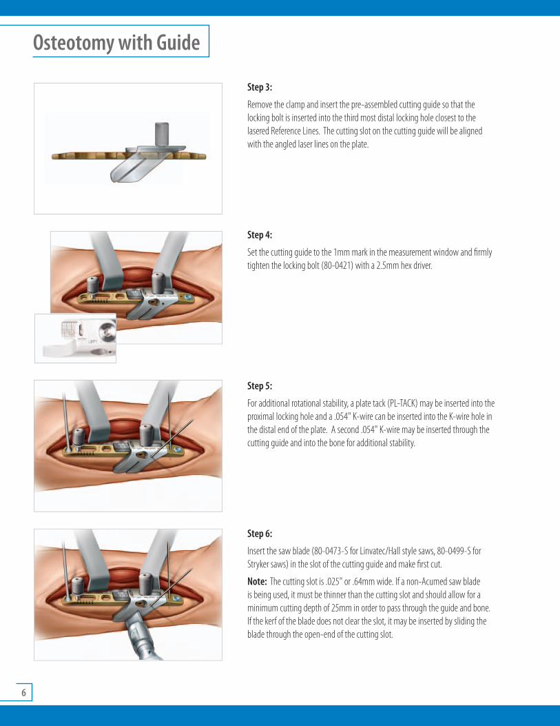
Step 3:
Remove the clamp and insert the pre-assembled cutting guide so that the
locking bolt is inserted into the third most distal locking hole closest to the
lasered Reference Lines. The cutting slot on the cutting guide will be aligned
with the angled laser lines on the plate.
Step 4:
Set the cutting guide to the 1mm mark in the measurement window and fi rmly
tighten the locking bolt (80-0421) with a 2.5mm hex driver.
Step 5:
For additional rotational stability, a plate tack (PL-TACK) may be inserted into the
proximal locking hole and a .054" K-wire can be inserted into the K-wire hole in
the distal end of the plate. A second .054" K-wire may be inserted through the
cutting guide and into the bone for additional stability.
Step 6:
Insert the saw blade (80-0473-S for Linvatec/Hall style saws, 80-0499-S for
Stryker saws) in the slot of the cutting guide and make fi rst cut.
Note: The cutting slot is .025" or .64mm wide. If a non-Acumed saw blade
is being used, it must be thinner than the cutting slot and should allow for a
minimum cutting depth of 25mm in order to pass through the guide and bone.
If the kerf of the blade does not clear the slot, it may be inserted by sliding the
blade through the open-end of the cutting slot.

7
Step 7:
Remove the K-wire inserted into the cutting guide and loosen the locking bolt
just enough to slide the cutting guide to the number corresponding to the
amount of shortening desired. Firmly retighten the locking bolt with the 2.5mm
hex driver.
Make sure that both sides of the ulna are re-aligned and re-insert the K-wire
through the cutting guide into the bone. Make the 2nd cut.
Note: The numbers on the bottom plate correspond to the desired amount of
bone to be resected, i.e. the “4” signifi es 4mm of resection.
Step 8:
Remove both K-wires, the cutting guide and plate tack. Slightly loosen (DO NOT
REMOVE) the temporary reduction peg in the measurement slot and excise the
bone wafer.
Note: If the gap does not close, make sure there is no bone left in the
osteotomy site near the plate. If this occurs the proximal and distal ends of the
bone may be rotated under the plate to remove any bone blocking reduction.
Step 9:
Place a bone clamp over the distal portion of the ulna and plate to reduce
the gap in between them. In the third most distal locking hole closest to the
osteotomy, drill using the threaded drill guide (80-0384) and 2.8mm drill
(80-0387) if pre-drilling was not preformed in STEP 2. Insert the proper length
3.5mm locking screw or non-locking screw. Remove the bone clamp and place
the threaded drill guide into the second distal locking hole.
Step 10:
Slightly loosen the reduction peg in the measurement slot. Place the reduction
clamp (80-0423) around the reduction peg and threaded drill guide. Reduce
the osteotomy gap with the reduction clamp and tighten the speed-lock wheel
on the clamp to maintain reduction hands-free.
Surgical Technique by William B. Geissler, M.D.

8
Figure 1 Figure 2
Osteotomy with Guide cont...
Step 11:
While holding the compression, drill the proximal end of the compression slot
with a 2.8mm drill, measure and insert a 3.5mm non-locking bicortical screw.
Ensure that the desired amount of shortening has been achieved by x-ray.
Step 12:
In the scalloped lag screw slot using a 3.5mm drill and the 3.5mm/2.8mm
drill guide (PL-2196), drill a glide hole in the near cortex at an angle across
the osteotomy site (Figure 1). Although the proximal or distal portion of
the slot may be used depending on the osteotomy location and desired
interfragmentary screw placement, the proximal slot is preferred. Next, place
the 2.8mm end of the drill guide into the 3.5mm glide hole and use a 2.8mm
drill to drill the far cortex (Figure 2).
Note: If the angle of the drill is too shallow, the drill may collide with the
adjacent screw in hole.
Step 13:
Measure and insert a non-locking 3.5mm screw into the scalloped lag screw
slot. Remove the reduction clamp. Drill the second distal locking hole before
removing the threaded drill guide. Measure and insert a locking screw into the
remaining distal locking hole.
Step 14:
Remove the temporary reduction peg. Measure and replace with a 3.5mm
non-locking screw. Drill, measure and insert a locking 3.5mm screw in the
remaining proximal locking hole.

9
Step 1:
Determine the amount of ulnar variance by preoperative x-rays. After exposing
the volar side of the ulna, place the plate 3-5cm proximal to the distal end of the
ulna. Secure the plate to the volar surface with one or more clamps. Make sure
the proximal and distal orientation of the plate is correct, as noted by the laser
marks on the plate.
Step 2:
Drill the most distal locking hole using the threaded drill guide (80-0384)
and 2.8mm drill (80-0387) and insert the proper length 3.5mm light blue
locking screw (COL-3XX0). In the proximal end of the measurement slot, drill
bicortically perpendicular to the plate and insert the temporary reduction peg
(80-0422) with a 2.5mm hex driver.
Option: You can pre-drill the two remaining distal locking holes in the same
manner with the threaded drill guide but DO NOT INSERT SCREWS. You can also
do this after the osteotomy has been achieved.
Step 3:
Using the 40° reference marks as a lines, create the osteotomy angled at least
40° perpendicular to the plate. Start the osteotomy at the most distal laser
mark. Create the osteotomy to the determined amount of shortening and excise
the bone wafer. A .054" K-wire in the distal end of the plate and a plate tack in
the proximal end may be used for additional stability.
Note: Each 40° reference line and space is 2mm wide. Additionally, the kerf of
the blade should be taken into consideration when creating the osteotomy.
Step 4:
Remove any K-wires and plate tacks. Make sure there is no bone left in the
osteotomy site near the plate. If this occurs the proximal and distal ends of
the bone may be rotated under the plate to remove any bone blocking the
reduction.
Place a bone clamp over the distal portion of the ulna and plate to reduce
the gap in between them. In the third most distal locking hole closest to the
osteotomy, drill using the threaded drill guide (80-0384) and 2.8mm drill
(80-0387) if pre-drilling was not preformed in STEP 2. Insert a locking or
bi-cortical non-locking screw.
Osteotomy w/o Guide Surgical Technique by William B. Geissler, M.D.

10
Figure 1 Figure 2
Osteotomy without Guide
Step 5:
Remove the bone clamp and place the threaded drill guide into the second
distal locking hole. Slightly loosen the reduction peg in the measurement slot.
Place the reduction clamp (80-0423) around the reduction peg and threaded
drill guide. Reduce the osteotomy gap with the reduction clamp and tighten the
speed-lock wheel on the clamp to maintain reduction hands-free.
Step 6:
While holding the compression, drill the proximal end of the compression slot
with a 2.8mm drill, measure and insert a 3.5mm non-locking bicortical screw.
Ensure that the desired amount of shortening has been achieved by x-ray.
Step 7:
In scalloped slot using a 3.5mm drill and the 3.5mm/2.8mm drill guide
(PL-2196), drill a glide hole in the near cortex at an angle across the osteotomy
site (1). Next, place the 2.8mm end of the drill guide into the 3.5mm glide
hole and use a 2.8mm drill to drill the far cortex (2). Measure and insert a non-
locking screw. The proximal or distal portion of the slot may be used depending
on the osteotomy location and desired interfragmentary screw placement. The
most proximal hole is preferred.
Note: If the angle of the drill is too shallow, the drill may collide with the
adjacent screw in hole.
Step 8:
Remove reduction clamp and drill the second distal locking hole before
removing the threaded drill guide. Measure and insert a locking screw into the
remaining distal locking hole. Remove the temporary reduction peg. Measure
and replace with a 3.5mm non-locking screw. Drill, measure and insert a
locking 3.5mm screw in the remaining proximal locking hole.

11
Note: The Ulnar Shortening Osteotomy Plate can be used with the following Acumed systems: Universal Tray and Congruent Locking Elbow Plate.
Ulnar Shortening Osteotomy Plate
Ulnar Shortening Plate PL-UL06
3.5mm Locking Cortical Screws
3.5mm x 8mm Locking Cortical Screw COL-3080
3.5mm x 10mm Locking Cortical Screw COL-3100
3.5mm x 12mm Locking Cortical Screw COL-3120
3.5mm x 14mm Locking Cortical Screw COL-3140
3.5mm x 16mm Locking Cortical Screw COL-3160
3.5mm x 18mm Locking Cortical Screw COL-3180
3.5mm Cortical Screws
3.5mm x 10mm Cortical Screw CO-3100
3.5mm x 12mm Cortical Screw CO-3120
3.5mm x 14mm Cortical Screw CO-3140
3.5mm x 16mm Cortical Screw CO-3160
3.5mm x 18mm Cortical Screw CO-3180
3.5mm x 20mm Cortical Screw CO-3200
Instrumentation
Ulnar Shortening Guide Left 80-0418
Ulnar Shortening Guide Right 80-0419
Ulnar Shortening Guide Bottom Plate 80-0420
Ulnar Shortening Locking Bolt 80-0421
Ulnar Shortening Reduction Peg 80-0422
Ulnar Shortening Reduction Clamp 80-0423
Ulnar Shortening Saw Blade - Hub Style L 80-0473-S
Ulnar Shortening Saw Blade - Hub Style S 80-0499-S
2.8mm Quick Release Drill 80-0387
3.5mm x 5" Quick Release Drill MS-DC35
2.8mm Locking Drill Guide 6-65mm 80-0384
.054" x 6" Guide Wire WS-1406ST
Tray
Instrument Tray 80-0513
Ordering Information

AcUMEDr5885 NW Cornelius Pass Road
Hillsboro, OR 97124
(888) 627-9957
www.acumed.net
Distributed by:
HNW00-03-B
Eff ective: 1/2010
These materials contain information about products that may or may not be available in any particular
country or may be available under diff erent trademarks in diff erent countries. The products may be
approved or cleared by governmental regulatory organizations for sale or use with diff erent indications
or restrictions in diff erent countries. Products may not be approved for use in all countries. Nothing
contained on these materials should be construed as a promotion or solicitation for any product or for
the use of any product in a particular way which is not authorized under the laws and regulations of
the country where the reader is located. Specifi c questions physicians may have about the availability
and use of the products described on these materials should be directed to their particular local sales
representative. Specifi c questions patients may have about the use of the products described in these
materials or the appropriateness for their own conditions should be directed to their own physician.