other visual programming paradigms in the remainder of the “programming paradigms section” we...
Post on 18-Dec-2015
222 views
TRANSCRIPT

Other Visual Programming Paradigms
In the remainder of the “programming paradigms section” we will look at
•Visual Logic Programming
•Programming with Relations (Database Programming)
•Basic Structure of Prolog: classical (textual) logic programming
•Execution Model of Prolog
•Visualizations of Prolog-Variants:
(TPM, MPL, Heterogenenous Visual Logic Programming,
Predicates and Pixels)
•Visual Functional Programming
•Clarity
•A Functional (set-based) View of Visual Logic Programming
•Visual Concurrent Constraint Programming
•Pictorial Janus and Toontalk

Rule-based Visual Programming
Universal Programming Paradigms•Visual Logic Programming (Visual Variants of Prolog, TPM etc.)•Visual Constraint Programming (Pictorial Janus, Toontalk)
Programming Pradigms for Programming with Pictures, particularly visual Simulations
•Production-system languages pixel-based: BitPicthigh-level image based: Agentsheets
(http://www.agentsheets.com)
Visual production systems generally have the formSearchPicture => Modification
This is interpreted as “if you find the picture SearchPicture in the current picture then apply the right-hand side modification to the current picture”

Visual Production Systemsused for implementing computations that directly operate on pictures.Mainly experimental research vehicle.
Only real-world application: Visual Simulation / Creating Animation
Example: BITPICT, a system for reasoning purely by diagram transformation.(For more information visit http://www.si.umich.edu/~furnas/)
The given rules (right) count the number of trees in a “tangled forrest” by reducing each tree to a single dot.

Visual Logic ProgrammingExperimental visual logic programming paradigm languages include: “Predicates and Pixels" [1], CUBE [2], Pictorial Janus [3], VLP [4], VPP [5], Mpl [6] and picture LP [7].
[1] Ringwood 1989 "Predicates and Pixels”. G. RingwoodNew Generation Computing, 7, 1989, pp. 59-70.
[2] "The CUBE Language” Marc A. Najork and Simon M. Kaplan. IEEE Workshop on Visual Languages 1991, Kobe, Japan.
[3] "Complete Visualizations of Concurrent Programs and their Executions”. Kenneth M. Kahn and Vijay A. Saraswat. IEEE Workshop on Visual Languages 1990, Skokie, Illinois.
[4] "VLP: A Visual Logic Programming Language”. Dider Ladret and Michel RueherJournal of Visual Languages and Computing (1991) 2, 163-188.
[5] "Visual Logic Programming”. L. F. Pau and H. OlasonJournal of Visual Languages and Computing (1991) 2, 3-15.
[6] "Mpl - a graphical programming environment for matrix processing”. Ricky YeungIEEE Workshop of Visual Languages 1988.
[7] "Pictures Depicting Pictures: On the Specification of Visual Languages by Visual Grammars”.Bernd Meyer. IEEE Workshop on Visual Languages 1992, Seattle, Washington.
Visual Logic Programming
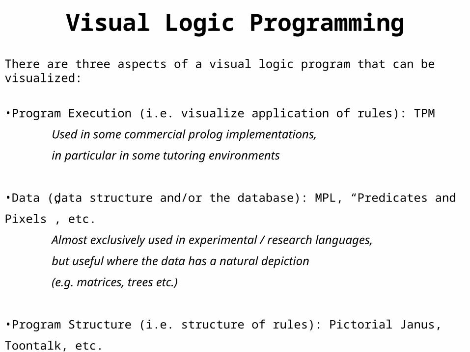
There are three aspects of a visual logic program that can be visualized:
•Program Execution (i.e. visualize application of rules): TPM
Used in some commercial prolog implementations,
in particular in some tutoring environments
•Data (data structure and/or the database): MPL, “Predicates and Pixels”, etc.
Almost exclusively used in experimental / research languages,
but useful where the data has a natural depiction
(e.g. matrices, trees etc.)
•Program Structure (i.e. structure of rules): Pictorial Janus, Toontalk, etc.
The most “visually complete” form of programming,
can form a good basis for execution visualization (e.g. Pictorial Janus)
Programming with Logic and Relations
•Relations (Tables) are a universal data representation
•Relations are used as the basis of Databases
•Prolog is a language for programming with logic & relations
Database Programming
Relational StructuresP1
P3
P2
P4
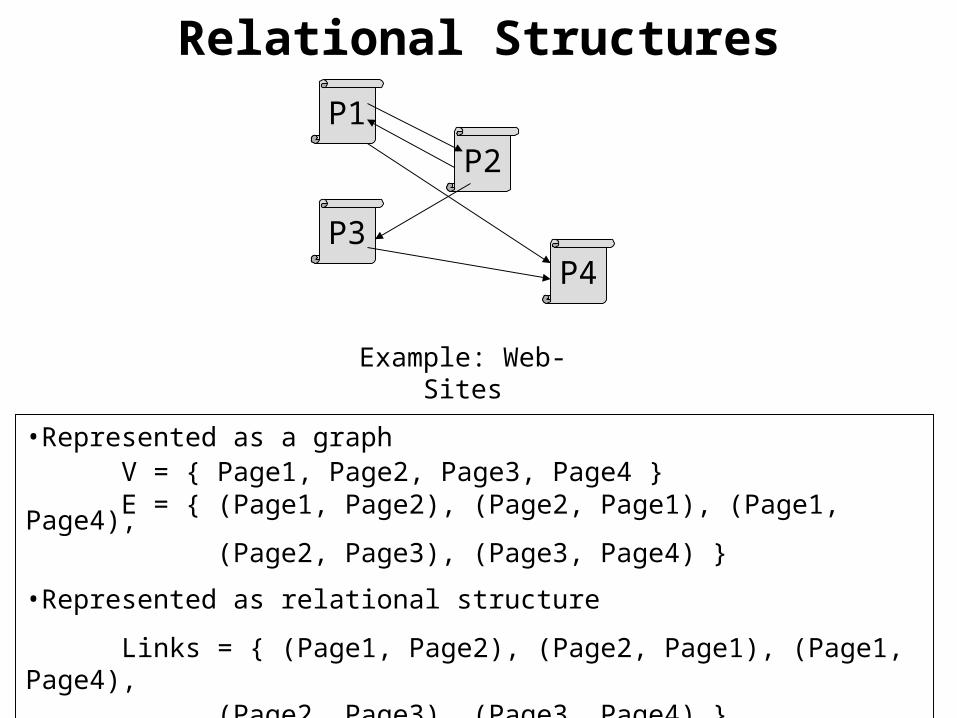
•Represented as a graph V = { Page1, Page2, Page3, Page4 }E = { (Page1, Page2), (Page2, Page1), (Page1, Page4),
(Page2, Page3), (Page3, Page4) }
•Represented as relational structure
Links = { (Page1, Page2), (Page2, Page1), (Page1, Page4),(Page2, Page3), (Page3, Page4) }
Example: Web-Sites
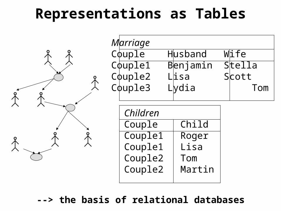
Representations as Tables
MarriageCouple Husband WifeCouple1 Benjamin StellaCouple2 Lisa ScottCouple3 Lydia Tom
ChildrenCouple ChildCouple1 RogerCouple1 LisaCouple2 TomCouple2 Martin
--> the basis of relational databases
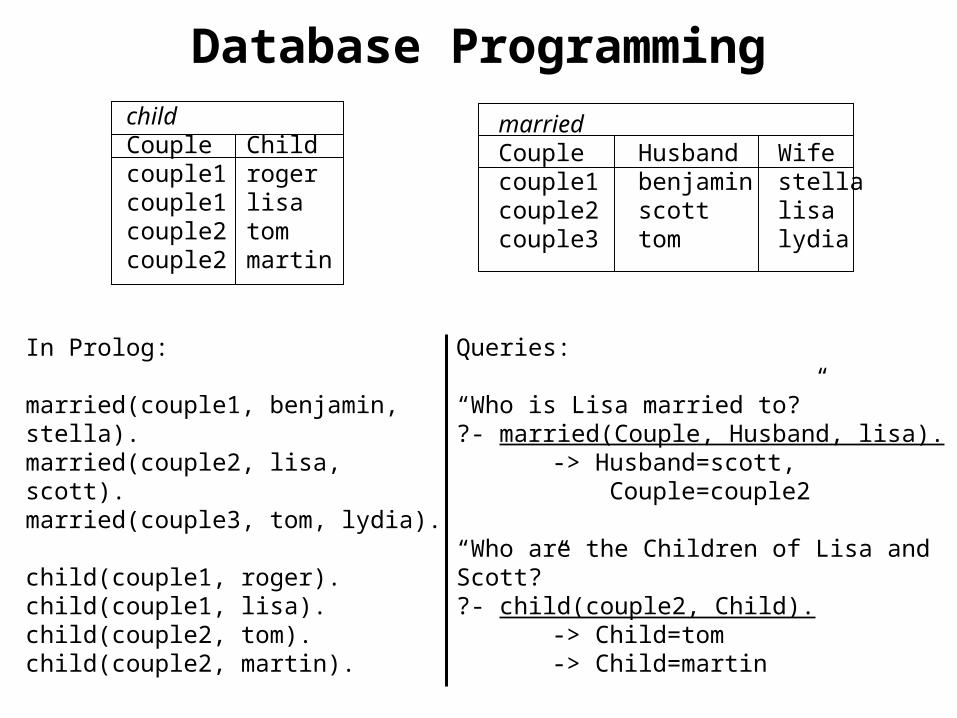
Database Programming
In Prolog:
married(couple1, benjamin, stella).married(couple2, lisa, scott).married(couple3, tom, lydia).
child(couple1, roger).child(couple1, lisa).child(couple2, tom).child(couple2, martin).
childCouple Childcouple1 rogercouple1 lisacouple2 tomcouple2 martin
marriedCouple Husband Wifecouple1 benjamin stellacouple2 scott lisa couple3 tom lydia
Queries:
“Who is Lisa married to?”?- married(Couple, Husband, lisa).
-> Husband=scott, Couple=couple2
“Who are the Children of Lisa and Scott?”?- child(couple2, Child).
-> Child=tom-> Child=martin
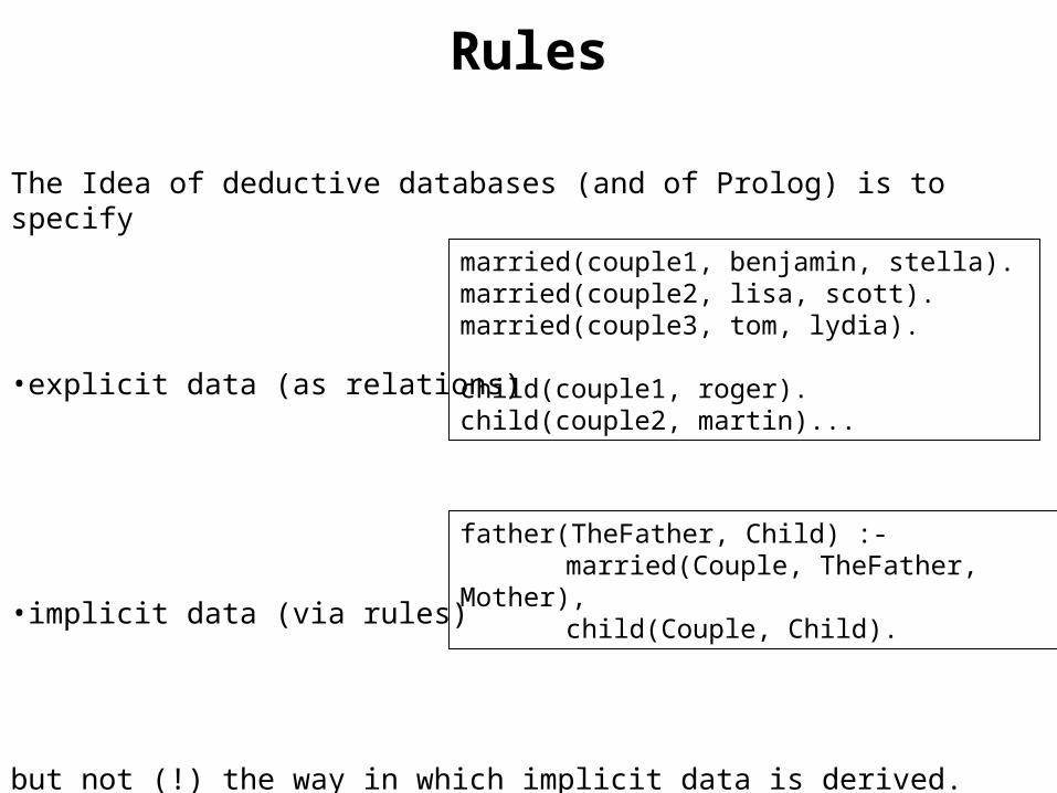
Rules
The Idea of deductive databases (and of Prolog) is to specify
•explicit data (as relations)
•implicit data (via rules)
but not (!) the way in which implicit data is derived.
married(couple1, benjamin, stella).married(couple2, lisa, scott).married(couple3, tom, lydia).
child(couple1, roger).child(couple2, martin)...
father(TheFather, Child) :- married(Couple, TheFather,
Mother),child(Couple, Child).
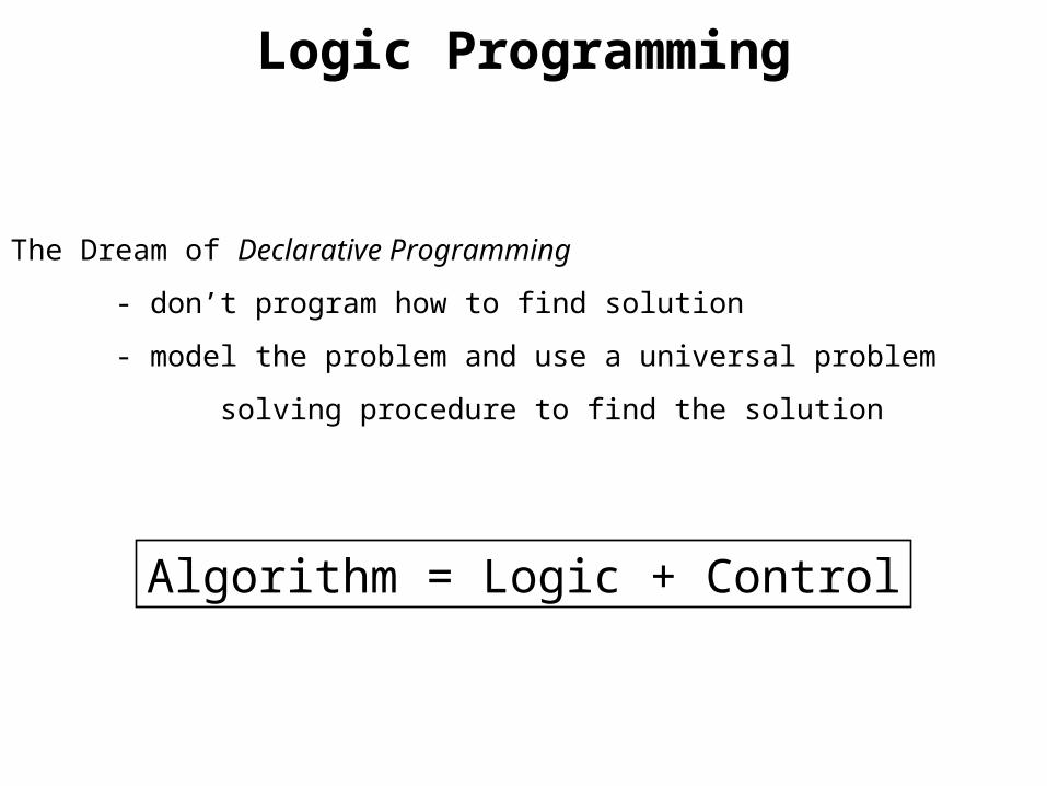
Logic Programming
The Dream of Declarative Programming
- don’t program how to find solution
- model the problem and use a universal problem
solving procedure to find the solution
Algorithm = Logic + Control

Procedural Interpretation of Rules
Logical deduction is the basis of programming
A if B1 and B2 and … Bn
Is re-interpreted as
to solve A, first solve B1 then B2 then … then Bn
or to execute A, first execute B1 then B2 then … then Bn

A short history of Prolog
Early 1970’s
Kowalski’s procedural interpretation of logic: Algorithm = Logic+Control
Colmerauer’s implementation of Prolog (Programmation en Logique)
Late 1970’s
D.H.D. Warren develops Prolog-10 Compiler (written in Prolog)
Prolog is not too well received in the US (Prolog / Lisp wars in AI)
1981
starts of Japanese Fifth Generation Project
1980’s
Europe and Australia start large Prolog projects (ECRC, Esprit…)
Height of “Decductive Databases”
Late 1980’s
numerous commercial Prolog implementations, Edinburgh standard, Development of Constraint logic Programming
Late 1980’s / 1990’s
Prolog widely used in AI
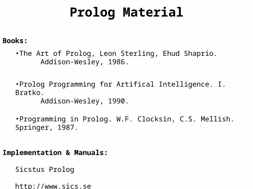
Prolog Material
Books:
•The Art of Prolog, Leon Sterling, Ehud Shaprio. Addison-Wesley, 1986.
•Prolog Programming for Artifical Intelligence. I. Bratko.Addison-Wesley, 1990.
•Programming in Prolog. W.F. Clocksin, C.S. Mellish. Springer, 1987.
Implementation & Manuals:
Sicstus Prolog
http://www.sics.sehttp://www.csse.monash.edu.au/software/sicstus/
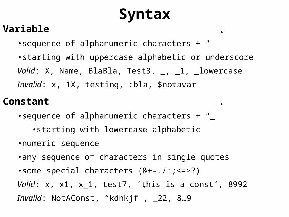
SyntaxVariable
•sequence of alphanumeric characters + “_”
•starting with uppercase alphabetic or underscore
Valid: X, Name, BlaBla, Test3, _, _1, _lowercase
Invalid: x, 1X, testing, :bla, $notavar
Constant•sequence of alphanumeric characters + “_”
•starting with lowercase alphabetic
•numeric sequence
•any sequence of characters in single quotes
•some special characters (&+-./:;<=>?)
Valid: x, x1, x_1, test7, ‘this is a const’, 8992
Invalid: NotAConst, “kdhkjf”, _22, 8…9
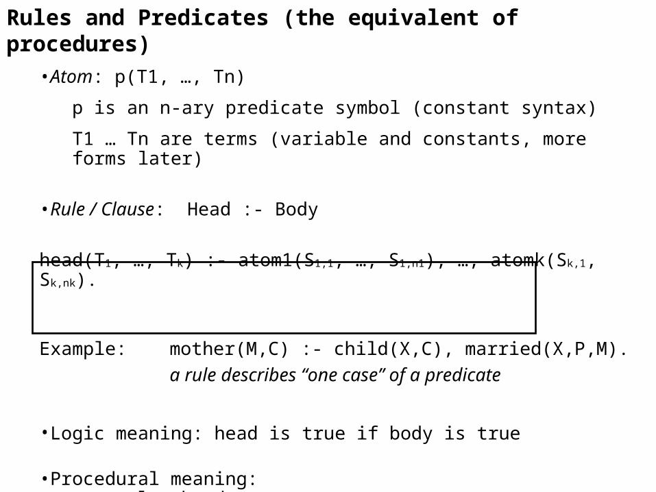
Rules and Predicates (the equivalent of procedures)
•Atom: p(T1, …, Tn)
p is an n-ary predicate symbol (constant syntax)
T1 … Tn are terms (variable and constants, more forms later)
•Rule / Clause: Head :- Body
head(T1, …, Tk) :- atom1(S1,1, …, S1,n1), …, atomk(Sk,1, Sk,nk).
Example: mother(M,C) :- child(X,C), married(X,P,M). a rule describes “one case” of a predicate
•Logic meaning: head is true if body is true
•Procedural meaning: to solve head,
solve atom1(S1,1, …, S1,n1), then … then atomk(Sk,1, Sk,nk).

Rules and Predicates (cont’d)
•Fact: person(joe).
a predicate with an empty body.
•Predicate definition:
a set of rules for the same predicate symbol.Interpreted as a disjunction.
parent(Person, Parent) :- father(Person, Parent).parent(Person, Parent) :- mother(Person, Parent).
•Query: syntactically just a body
normally with free variables that are bound in the answer.
parent(martin, X). -> the answer is X=scott, X=lisa.

Example: Database Programming
Which predicates are required to model this?

State Example
is_state_of(nsw, australia).is_state_of(nt, australia).is_state_of(qld, australia).is_state_of(vic, australia).is_state_of(tas, australia).is_state_of(wa, australia).is_state_of(act, australia).
border(wa,nt).border(wa,sa).border(sa,nt).border(sa,qld).border(sa,vic).border(sa,nsw).border(nt,qld).border(qld,nsw).border(nsw,vic).
Queries: ?- border(sa,S).?- is_state_of(S, australia).?- is_state_of(vic, C).
?- border(vic, X) *** No
Rules:
border(X,Y) :- border(Y,X)
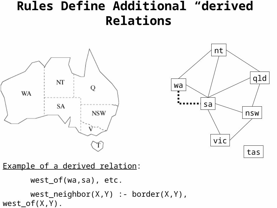
Rules Define Additional “derived” Relations
wa
nt
qld
sansw
vic
tas
Example of a derived relation:
west_of(wa,sa), etc.
west_neighbor(X,Y) :- border(X,Y), west_of(X,Y).

Execution of Prolog Programs
father(charles, philip).
father(ana, george).
father(philip, tom).
mother(charles, ana).
parent(Pers, Par) :- father(Pers, Par).
parent(Pers, Par) :- mother(Pers, Par).
grandparent(Pers, Gpar) :-parent(Pers, Par), parent(Par, Gpar).

Simplified Interpreter (for ground goals)
Input: A ground goal G and a program P
Output: yes if G is a consequence of P (“is true in P”),
no otherwise
Initialize resolvent to G
Algorithm:
While (resolvent A1, …, An is not empty) do
choose a goal A from the resolvent
choose a ground instance of a clause
A’ :- B1, …, Bn from P
such that A and A’ are identical
(exit with “no” if no such clause)
replace A by B1, …, Bn in the resolvent
If (resolvent is empty) answer “yes” else answer “no”

Multiple Solutions
father(charles, philip).
father(ana, george).
father(philip, tom).
mother(charles, ana).
parent(Pers, Par) :- father(Pers, Par).
parent(Pers, Par) :- mother(Pers, Par).
grandparent(Pers, Gpar) :-parent(Pers, Par), parent(Par, Gpar).
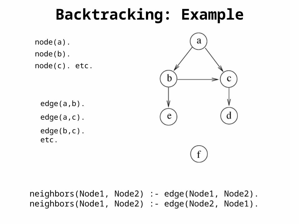
Backtracking: Example
edge(a,b).
edge(a,c).
edge(b,c). etc.
node(a).
node(b).
node(c). etc.
neighbors(Node1, Node2) :- edge(Node1, Node2).neighbors(Node1, Node2) :- edge(Node2, Node1).

neighbors(Node1, Node2) :- edge(Node1, Node2).neighbors(Node1, Node2) :- edge(Node2, Node1).

Execution Visualization in VPL
Mostly based on tree-representations of the derivation structure similar to those we have used when analyzing Prolog derivations.
The standard are And/Or-Trees, in which the branches to children denote either disjunctions of conjunctive subgoals, corresponding to the different bodies of a predicate..
A more elaborate visualization is used in the “Transparent Prolog Machine” (TPM),a system for teaching Prolog. These diagrams are called Aorta diagrams:
However, visualization of execution is
closer to algorithm animation and visual debugging than to visual
programming,
since the actual programming process is completely textual
For detailed information on the TPM see The Transparent Prolog Machine : Visualizing Logic Programs by Marc Eisenstadt, Mike Brayshaw, Jocelyn PaineKluwer Academic Publishers, 1992.
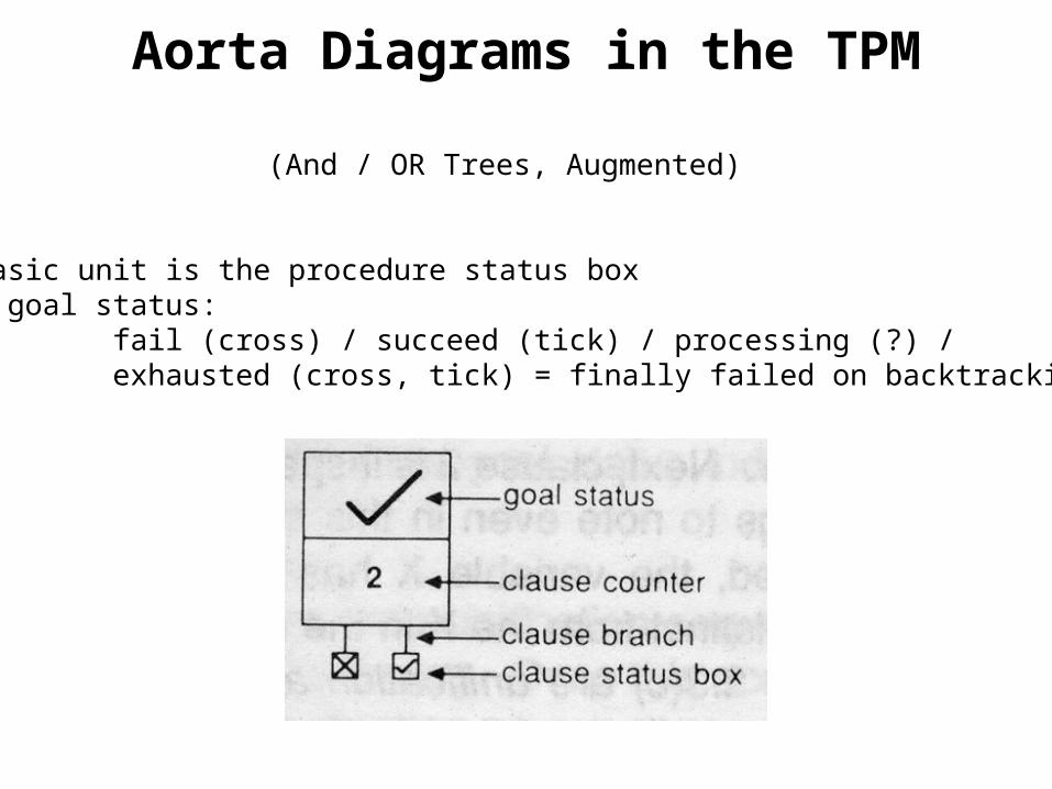
Aorta Diagrams in the TPM
(And / OR Trees, Augmented)
The basic unit is the procedure status boxgoal status:
fail (cross) / succeed (tick) / processing (?) /exhausted (cross, tick) = finally failed on backtracking

Dynamics of Procedure Status Box
eats(joe, hamburgers).eats(fred, X). eats(X, bread)
Status boxes during executionof eats(X, rubbish) for the program
Watch how the clause counter is incremented and the status ofthe separate clauses are indicated.
The annotation indicates the parameters unification (see below)
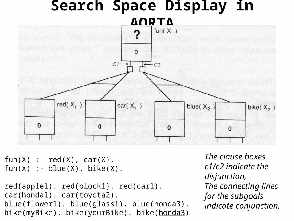
Search Space Display in AORTA
fun(X) :- red(X), car(X).fun(X) :- blue(X), bike(X).
red(apple1). red(block1). red(car1).car(honda1). car(toyota2).blue(flower1). blue(glass1). blue(honda3).bike(myBike). bike(yourBike). bike(honda3)
The clause boxesc1/c2 indicate thedisjunction,The connecting linesfor the subgoals indicate conjunction.

Full AORTA Execution Example
older(X,Y) :- age(X, AgeOfX), age(Y, AgeOfY), AgeOfX > AgeOfY.
age(john, 27).age(tom, 18).age(sue, 24).
Note
the execution timestamps given by thesmall italics and theargument passing arrows