otto bock tt design - pcs product...
TRANSCRIPT
Lesson Error! Style not defined.
Seminar Otto Bock Data Station – Measuring 1
Notes
Otto Bock TT Design
Functionality
The Otto Bock TT Design application helps you create a transtibial test
socket with the matching components.
Using modern CAD/CAM technology, it offers the following advantages:
Lower investment and reduced risk for the CPO
Support for the CPO during individual patient care
Comfort for the patient – no plaster cast
Simple, logical CAD application technology
Modern mass customization (CAM technology) as a service
Ability to reproduce the residual limb and socket data precisely
Compatible system consisting of a custom liner and test socket
Lesson Error! Style not defined.
Seminar Otto Bock Data Station – Measuring 2
Notes
When working with the Otto Bock TT Design application, the following
steps can be identified:
Working with the Patient
Palpating the residual limb and recording the residual limb
measurements
Applying a Calibration piece to the residual limb
Taking a digital photo of the anterior and lateral sides of the
residual limb
Working in the Otto Bock TT Design Application
Entering the recorded patient measurements
Reading and processing the digital images
Creating and editing a three-dimensional socket model
Optional: Selecting and configuring prosthesis components
Ordering the resulting product (socket and optional
components) from Otto Bock via e-mail

Lesson Error! Style not defined.
Seminar Otto Bock Data Station – Measuring 3
Notes
The Three-Dimensional Socket Model
After processing the digital pictures, the TT Design application
calculates the socket shape using a “morphing” algorithm.
This algorithm adjusts the chosen reference socket model to the
calibrated residual limb contours obtained from the digital photos. It
changes and reshapes the reference socket model until it matches the
contours shown in the digital photo.
#1 to be replaced
The illustrations below show how the reference model “grows” into the
correct contour during the morphing process. The result is an actual
socket model and not simply a reconstruction of the residual limb.

Lesson Error! Style not defined.
Seminar Otto Bock Data Station – Measuring 4
Notes
#2 to be replaced
The prominent areas of the residual limb are located directly on the
digital photos.
#3 to be replaced

Lesson Error! Style not defined.
Seminar Otto Bock Data Station – Measuring 5
Notes
Clinical Knowledge Integrated in the System
#4 to be replaced
The following fundamental changes are included in the calculated
socket model:
Volume reduction by 7-9% (dependent upon socket style)
Distal extension by 18 mm
Prominent tibial crest (tibial crest is applied)
Positive patches + 4 mm (e.g. fibula patch)
Negative patches – 3 mm (e.g. patella bar patch)
Medial condyle support – 3 mm
Posterior patch = 0 mm
You can individually adjust any of these features.

Lesson Error! Style not defined.
Seminar Otto Bock Data Station – Measuring 6
Notes
Manufacturing Process
After placing the order with Otto Bock via e-mail, Otto Bock Fabrication
Service will use a modern CAD/CAM process to create a test socket
which will be delivered to you for fitting along with the selected
components.
Fitting
After receiving the socket and assembling the test prosthesis, a walking
trial can be carried out.
#5 to be replaced
Individual problem areas can be rectified by heating and
reshaping the transparent test socket.

Lesson Error! Style not defined.
Seminar Otto Bock Data Station – Measuring 7
Notes
Tools
When working with the Otto Bock TT Design application, you require
the following tools:
1 Body caliper to measure the residual limb (743S20)
2 Calibration piece for digital photography (743S30)
3 Residual limb sock 2-pack (99B90=2)
4 Digital camera (743L234)
5 Black background (743S50)
6 Knee angle check (743S40)
7 Velcro patches to attach the Calibration piece (623Z20)

Lesson Error! Style not defined.
Seminar Otto Bock Data Station – Measuring 8
Notes
Working with the Patient
Seat the patient on the black background so that the entire residual limb
being photographed is located in front of the black background.
Obtain an impression of the soft tissues and bony regions of the
residual limb by palpating it.
Put the white residual limb sock onto the patient so that there
are no distal folds.
The TT Design kit includes a residual limb sock for all residual
limb sizes. This is the only type of sock that can be used for this
process. Please do not pull the sock up too tight, since this can
affect the residual limb shape.
Lesson Error! Style not defined.
Seminar Otto Bock Data Station – Measuring 9
Notes
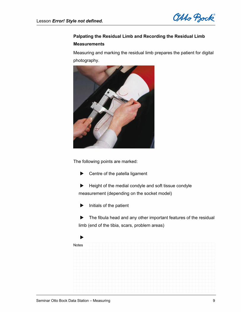
Palpating the Residual Limb and Recording the Residual Limb Measurements
Measuring and marking the residual limb prepares the patient for digital
photography.
The following points are marked:
Centre of the patella ligament
Height of the medial condyle and soft tissue condyle
measurement (depending on the socket model)
Initials of the patient
The fibula head and any other important features of the residual
limb (end of the tibia, scars, problem areas)

Lesson Error! Style not defined.
Seminar Otto Bock Data Station – Measuring 10
Notes
Use the body caliper, which has a slot in each caliper arm, to
mark the centre of the patella ligament.
To do so, press the upper caliper arm between the lower edge
of the patella and the tibial tuberosity and mark the centre of the
patella bar. This method is easy to reproduce. Laterally elongate the
line slightly so that the centre of the patella ligament can also be
seen on the lateral photo.
Attention
Correctly marking the centre of the patella ligament is crucial for
the correct socket length.
To create a trans-condylar socket, mark the medial condyle
height and measure the soft tissue condyle dimension.
Move the body caliper proximally starting from the centre of the
knee and bring the caliper arms together to determine the lowest
point of the condyle socket; mark it laterally through the slot.
In this position, read the soft tissue condyle measurement from
the body caliper and note this value on the patella. It is then recorded
on the photo and is available for socket production.
Marking the condyle height establishes the lowest point of the
condyle socket, not the height of the socket edge.

Lesson Error! Style not defined.
Seminar Otto Bock Data Station – Measuring 11
Notes
Write the patient’s initials and the soft tissue condoyle
measurement onto the patella.
For PTB sockets, mark the height of the socket edge at the
medial tibial plateau. A soft tissue condyle measurement is not
required in this case.
Mark the fibula head and any other important features of the
residual limb that could lead to pressure points and therefore have to
be considered when creating the socket model onto the sock. Also,
mark the highest point of the elevated area (patch) with a cross.
Creating the Digital Photos of the Residual Limb
Two digital photographs of the residual limb are required as the basis
for calculating the three-dimensional socket model in the TT Design
application:
The anterior view

Lesson Error! Style not defined.
Seminar Otto Bock Data Station – Measuring 12
Notes
The lateral view
The Calibration piece, the black background, and of course the digital
camera are required for this purpose.
Consider the following during photography:
Use the black background in order to create a good contrast
relative to the residual limb. On the photo, the entire white residual
limb sock must be underlain with the black background.

Lesson Error! Style not defined.
Seminar Otto Bock Data Station – Measuring 13
Notes
Ensure that the background is not pressed against the residual
limb, since this affects the shape or the residual limb contour on
the photo.
Check the knee flexion angle of the seated patient with the
supplied knee angle (15°).
Check the seating position of the patient. The amputated side is
frequently stretched forward, which causes interior rotation of the
residual limb. When taking the digital photos, the spinae should
be parallel to the back of the chair.
The residual limb must be photographed at maximum optical zoom (3x).
Ensure that the distance is approximately 1m. This is normally
the case when the residual limb fills picture in the viewfinder at
maximum zoom.
Use the Velcro patches to attach the Calibration piece along
the tibial crest. The Calibration piece helps to position the camera
and to calibrate the residual limb measurements.
Ensure that the Calibration piece is not tilted laterally or medially
when it is attached. The proximal or distal position is not
significant. The Calibration piece must be fully visible on the

Lesson Error! Style not defined.
Seminar Otto Bock Data Station – Measuring 14
Notes
photo.
Correct Use of the Calibration piece
The fins of the Calibration piece help you find the correct
camera position for anterior and lateral photos.
The reflector points are used to calibrate the software as a
reference measurement used to determine the residual limb
dimensions.
Here is how you determine the correct camera position for anterior and
lateral photos with the help of the Calibration piece:
Only the edges of the fins on the Calibration piece must be
visible.
Lesson Error! Style not defined.
Seminar Otto Bock Data Station – Measuring 15
Notes
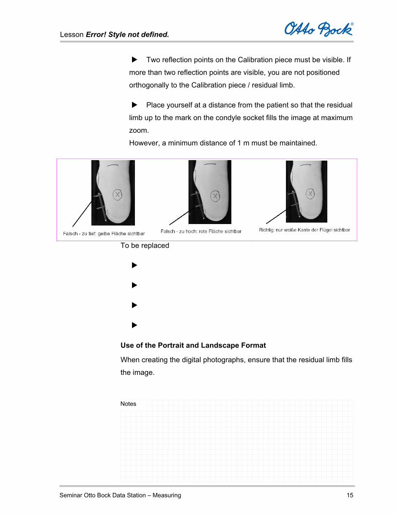
Two reflection points on the Calibration piece must be visible. If
more than two reflection points are visible, you are not positioned
orthogonally to the Calibration piece / residual limb.
Place yourself at a distance from the patient so that the residual
limb up to the mark on the condyle socket fills the image at maximum
zoom.
However, a minimum distance of 1 m must be maintained.
To be replaced
Use of the Portrait and Landscape Format
When creating the digital photographs, ensure that the residual limb fills
the image.

Lesson Error! Style not defined.
Seminar Otto Bock Data Station – Measuring 16
Notes
Use the portrait format for the anterior photo.
Use the landscape format for the lateral photo.
The illustration below shows a correct lateral photo in landscape format,
with the residual limb filling the image.
Lesson Error! Style not defined.
Seminar Otto Bock Data Station – Measuring 17
Notes
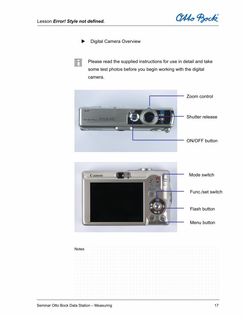
Digital Camera Overview
Please read the supplied instructions for use in detail and take
some test photos before you begin working with the digital
camera.
Zoom control
Shutter release
ON/OFF button
Mode switch
Func./set switch
Flash button
Menu button
Lesson Error! Style not defined.
Seminar Otto Bock Data Station – Measuring 18
Notes
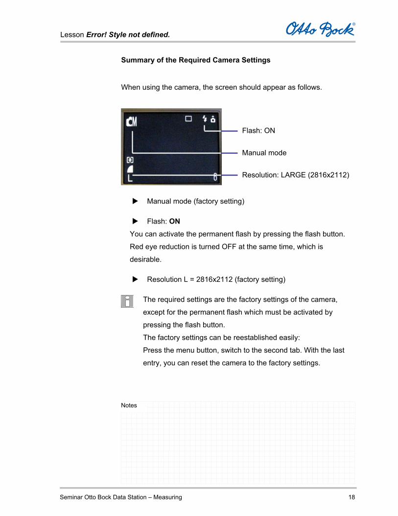
Summary of the Required Camera Settings
When using the camera, the screen should appear as follows.
Manual mode (factory setting)
Flash: ON You can activate the permanent flash by pressing the flash button.
Red eye reduction is turned OFF at the same time, which is
desirable.
Resolution L = 2816x2112 (factory setting)
The required settings are the factory settings of the camera,
except for the permanent flash which must be activated by
pressing the flash button.
The factory settings can be reestablished easily:
Press the menu button, switch to the second tab. With the last
entry, you can reset the camera to the factory settings.
Flash: ON
Manual mode
Resolution: LARGE (2816x2112)
Lesson Error! Style not defined.
Seminar Otto Bock Data Station – Measuring 19
Notes
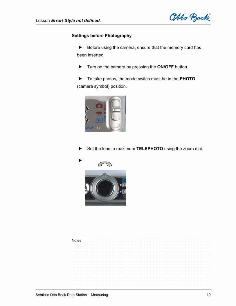
Settings before Photography
Before using the camera, ensure that the memory card has
been inserted.
Turn on the camera by pressing the ON/OFF button.
To take photos, the mode switch must be in the PHOTO
(camera symbol) position.
Set the lens to maximum TELEPHOTO using the zoom dial.

Lesson Error! Style not defined.
Seminar Otto Bock Data Station – Measuring 20
Notes
Taking Photos
Push the SHUTTER BUTTON down halfway.
Position the camera so that the crosshair inside the viewfinder (auto
focus field) points to the patient’s residual limb.
When you press the SHUTTER BUTTON fully, the photo is
taken immediately. Do not move the camera until you hear the sound
of the shutter.
Every photo must be taken with the flash activated.
Lesson Error! Style not defined.
Seminar Otto Bock Data Station – Measuring 21
Notes
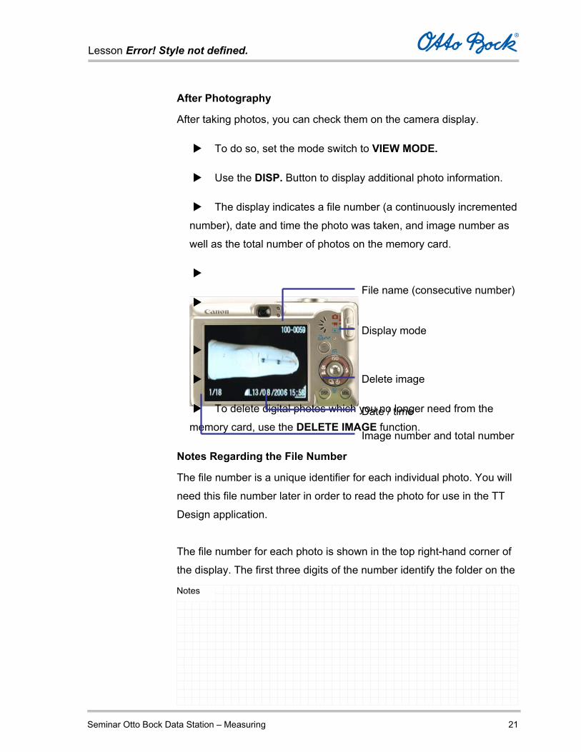
After Photography
After taking photos, you can check them on the camera display.
To do so, set the mode switch to VIEW MODE.
Use the DISP. Button to display additional photo information.
The display indicates a file number (a continuously incremented
number), date and time the photo was taken, and image number as
well as the total number of photos on the memory card.
To delete digital photos which you no longer need from the
memory card, use the DELETE IMAGE function.
Notes Regarding the File Number
The file number is a unique identifier for each individual photo. You will
need this file number later in order to read the photo for use in the TT
Design application.
The file number for each photo is shown in the top right-hand corner of
the display. The first three digits of the number identify the folder on the
Date / time
File name (consecutive number)
Image number and total number
Delete image
Display mode

Lesson Error! Style not defined.
Seminar Otto Bock Data Station – Measuring 22
Notes
memory card. The four digits to the right of the dash identify the actual
photo number.
The file name of the corresponding image file for TT Design is
comprised of IMG (for image), leading zeros (0), and the right-hand part
of the file number. The file has the extension .JPG.
For example, the file name for photo number 419-1976 will be
IMG_1976.JPG.
If you are photographing more than one patient, always make a
note of the corresponding photo numbers for the patient.
Transmitting the Photos from the Camera to the Computer
Two options are available to complete this job:
Connecting the camera to your computer directly via USB
Connect the camera to your PC using the supplied USB cable.
The camera is recognized as a file storage device. If not, then please
install the supplied camera software on your PC.
You can now use Windows Explorer to save the photos in a file
folder so they are available for socket design.

Lesson Error! Style not defined.
Seminar Otto Bock Data Station – Measuring 23
Notes
Removing the Memory Card
Press the memory card to release the locking mechanism; now
you can remove the SD memory card from the camera.
Then insert it into the corresponding card reader on your
computer and transfer the photos to the desired storage location.

Lesson Error! Style not defined.
Seminar Otto Bock Data Station – Operating Example 1
Notes
Operating Example for the Otto Bock Data Station On the following pages, you will find a brief sample description of the
following operating steps:
Launching the Otto Bock Data Station
Creating patient data for a patient
Creating the group My Patients and assigning the new patient
to this group
Opening a job in TT Design for this patient
Submitting the purchase order to Otto Bock after the job is
completed
Closing the Otto Bock Data Station
Lesson Error! Style not defined.
Seminar Otto Bock Data Station – Operating Example 2
Notes
Launching the Otto Bock Data Station
To launch the Otto Bock Data Station, click the
symbol on the Windows XP Desktop.
Alternatively, select the entry in the
Windows start menu.
The program is launched and you see a start-up screen with notes
regarding the version and legal notices for the use of the Otto Bock
Data Station during this phase.
Lesson Error! Style not defined.
Seminar Otto Bock Data Station – Operating Example 3
Notes
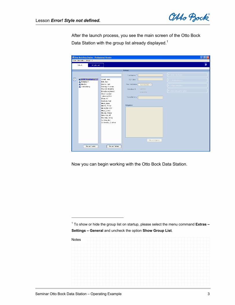
After the launch process, you see the main screen of the Otto Bock
Data Station with the group list already displayed.1
Now you can begin working with the Otto Bock Data Station.
1 To show or hide the group list on startup, please select the menu command Extras – Settings – General and uncheck the option Show Group List.
Lesson Error! Style not defined.
Seminar Otto Bock Data Station – Operating Example 4
Notes
Creating patient data for a patient
Create the patient data for a new patient named Theodor Müller.
Click the button New Patient.
Enter the last name and first name.
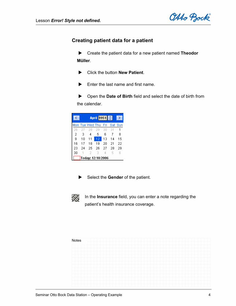
Open the Date of Birth field and select the date of birth from
the calendar.
Select the Gender of the patient.
In the Insurance field, you can enter a note regarding the
patient’s health insurance coverage.

Lesson Error! Style not defined.
Seminar Otto Bock Data Station – Operating Example 5
Notes
Up to this point, you have entered the following data.
Click the button Optional Data and enter additional data for the
patient.
Lesson Error! Style not defined.
Seminar Otto Bock Data Station – Operating Example 6
Notes
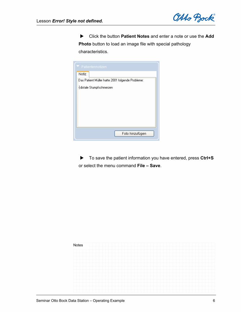
Click the button Patient Notes and enter a note or use the Add Photo button to load an image file with special pathology
characteristics.
To save the patient information you have entered, press Ctrl+S
or select the menu command File – Save.

Lesson Error! Style not defined.
Seminar Otto Bock Data Station – Operating Example 7
Notes
Creating the group My Patients
Now you will create a group with the name My Patients and assign the
patient Müller to this new group.
In our example, three additional groups already exist – Bergmann,
Josef’s Patienten, and Svedenborg.
Select any entry in the group list and then select the menu
command File – Group – New Favorite.
Lesson Error! Style not defined.
Seminar Otto Bock Data Station – Operating Example 8
Notes
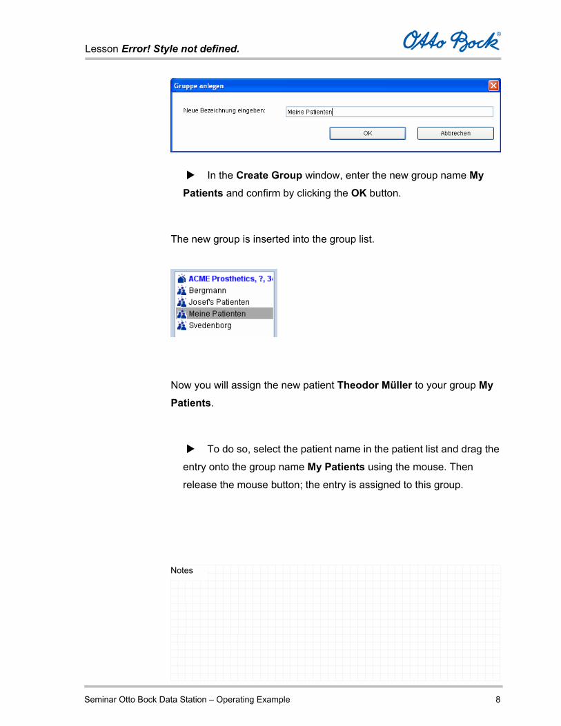
In the Create Group window, enter the new group name My Patients and confirm by clicking the OK button.
The new group is inserted into the group list.
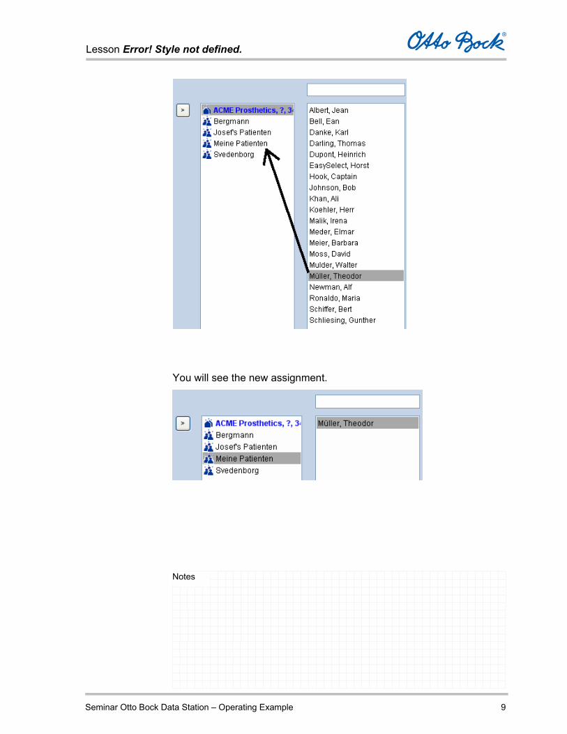
Now you will assign the new patient Theodor Müller to your group My Patients.
To do so, select the patient name in the patient list and drag the
entry onto the group name My Patients using the mouse. Then
release the mouse button; the entry is assigned to this group.
Lesson Error! Style not defined.
Seminar Otto Bock Data Station – Operating Example 9
Notes
You will see the new assignment.

Lesson Error! Style not defined.
Seminar Otto Bock Data Station – Operating Example 10
Notes
You can also verify the assignment by selecting the patient name
and clicking the button Group Membership.
The group memberships of the selected patient are displayed in
the window. This is useful if a patient entry is assigned to several
groups.
To remove a patient entry from a group, select the entry and
press Delete or select the command Remove Patient from the
context menu (right mouse button).
Lesson Error! Style not defined.
Seminar Otto Bock Data Station – Operating Example 11
Notes
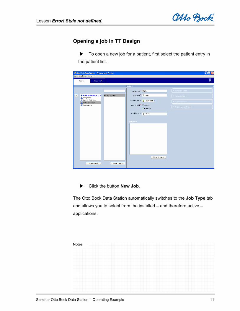
Opening a job in TT Design
To open a new job for a patient, first select the patient entry in
the patient list.
Click the button New Job.
The Otto Bock Data Station automatically switches to the Job Type tab
and allows you to select from the installed – and therefore active –
applications.

Lesson Error! Style not defined.
Seminar Otto Bock Data Station – Operating Example 12
Notes
For our example, select Transtibial.
Select the corresponding option in the option menu that is
displayed:

Lesson Error! Style not defined.
Seminar Otto Bock Data Station – Operating Example 13
Notes
Socket Design – Create a TT Design socket by entering
measurements and editing the socket view.
Component Selection – Select additional components to
supplement the socket (prosthesis components).
You will now finish processing the job Transtibial Socket for the patient
Theodor Müller.
Click Next to move to the Specification tab.
There you can enter measurements and information regarding the
socket material.
Lesson Error! Style not defined.
Seminar Otto Bock Data Station – Operating Example 14
Notes
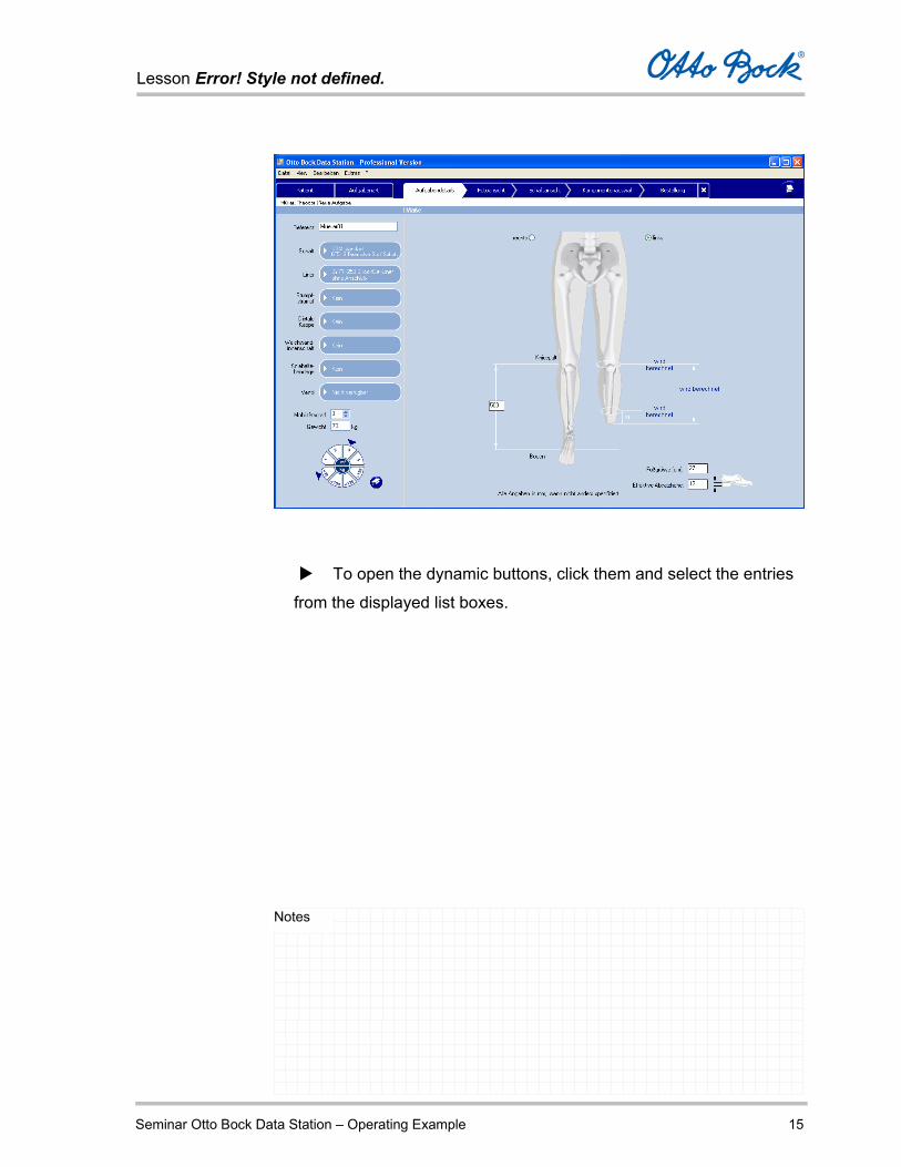
Entries in the Specification tab
In the Specification tab, you enter the following information regarding
the socket and the patient:
Reference number of the job
Socket material
Liner
Residual limb sock
Distal cap
Outer liner
Knee support sleeve
Valve
Mobility grade
Weight
Amputated side
Measurement from the medial tibial plateau to the floor
Foot size
Effective heel height
Complete all fields and list boxes according to the example.
Lesson Error! Style not defined.
Seminar Otto Bock Data Station – Operating Example 15
Notes
To open the dynamic buttons, click them and select the entries
from the displayed list boxes.

Lesson Error! Style not defined.
Seminar Otto Bock Data Station – Operating Example 16
Notes
After you have completed all entries in the Specifications tab
according to our illustration, move to the next tab by clicking Photo View.
This is where you load the anterior and lateral digital photos and
calibrate them for the subsequent digital socket calculation.
Entries in the Photo View tab
In the Photo View tab, you complete the following steps:
Loading the anterior and lateral digital photos

Lesson Error! Style not defined.
Seminar Otto Bock Data Station – Operating Example 17
Notes
Graphically marking the calibration tool and other prominent
features of the residual limb
Optionally editing the generated residual limb contour
Adding patches and medial support

Lesson Error! Style not defined.
Seminar Otto Bock Data Station – Operating Example 18
Notes
Loading the anterior and lateral digital photos
After switching to the Photo View tab, the dialogue used to load the
digital photos opens automatically.
Drag the digital photos from the overview bar on the top into the
two windows Anterior Photo and Lateral Photo.
By clicking the top line with the name of the file folder, you can
change the folder.
Use the two identified digital photos for our example.
Confirm with Next.
Lesson Error! Style not defined.
Seminar Otto Bock Data Station – Operating Example 19
Notes
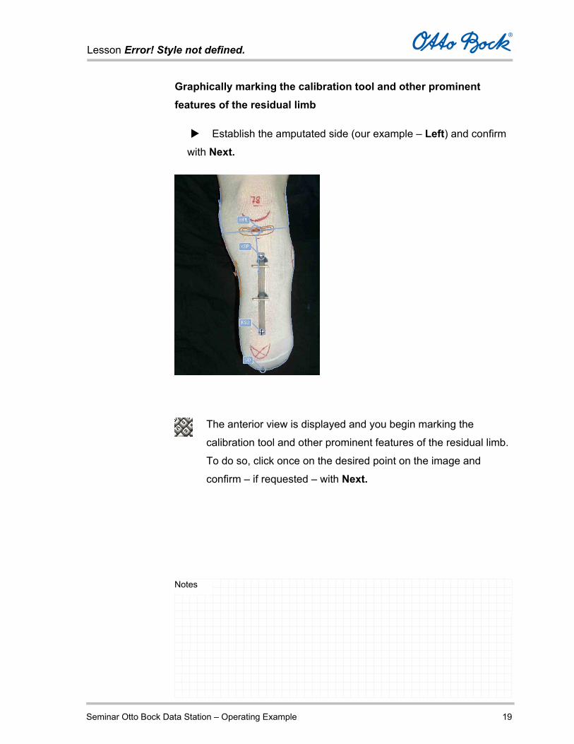
Graphically marking the calibration tool and other prominent features of the residual limb
Establish the amputated side (our example – Left) and confirm
with Next.
The anterior view is displayed and you begin marking the
calibration tool and other prominent features of the residual limb.
To do so, click once on the desired point on the image and
confirm – if requested – with Next.

Lesson Error! Style not defined.
Seminar Otto Bock Data Station – Operating Example 20
Notes
Distal calibration tool mark (KSD)
Proximal calibration tool mark (KSP)
Residual limb end mark (SD)
Patella ligament mark (MPL)
Condyle socket setting
After marking all points, you can make corrections by moving the
marks.
After the process for marking the points is completed, TT Design
automatically generates a residual limb contour. You can optionally edit
the contour or graphically position patches on the image.
You will find notes regarding these jobs in the following individual
sections.
Optionally editing the generated residual limb contour
Adding patches and medial support
Lesson Error! Style not defined.
Seminar Otto Bock Data Station – Operating Example 21
Notes
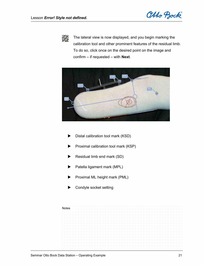
The lateral view is now displayed, and you begin marking the
calibration tool and other prominent features of the residual limb.
To do so, click once on the desired point on the image and
confirm – if requested – with Next.
Distal calibration tool mark (KSD)
Proximal calibration tool mark (KSP)
Residual limb end mark (SD)
Patella ligament mark (MPL)
Proximal ML height mark (PML)
Condyle socket setting

Lesson Error! Style not defined.
Seminar Otto Bock Data Station – Operating Example 22
Notes
After marking all points, you can make corrections by moving the
marks.
After the process for marking the points is completed, TT Design
automatically generates a residual limb contour. You can optionally edit
the contour or graphically position patches on the image.
You will find notes regarding these jobs in the following individual
sections.
Optionally editing the generated residual limb contour
Adding patches and medial support
Lesson Error! Style not defined.
Seminar Otto Bock Data Station – Operating Example 23
Notes
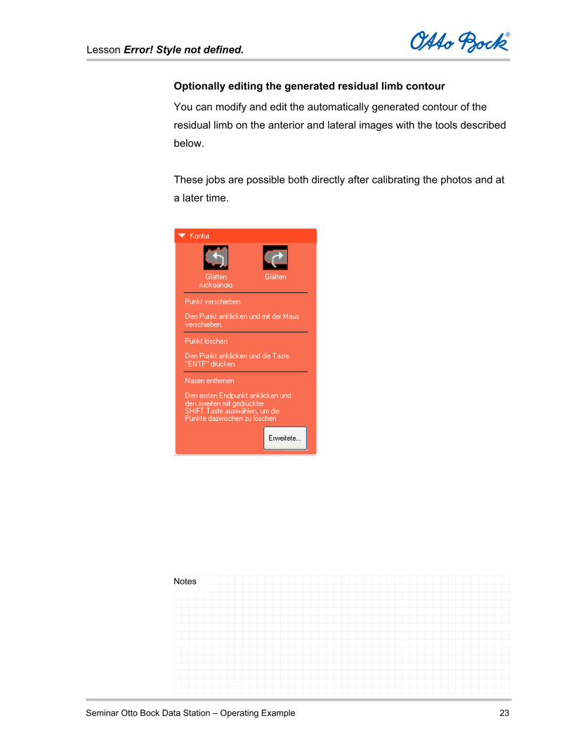
Optionally editing the generated residual limb contour
You can modify and edit the automatically generated contour of the
residual limb on the anterior and lateral images with the tools described
below.
These jobs are possible both directly after calibrating the photos and at
a later time.
Lesson Error! Style not defined.
Seminar Otto Bock Data Station – Operating Example 24
Notes
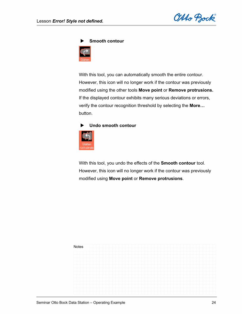
Smooth contour
With this tool, you can automatically smooth the entire contour.
However, this icon will no longer work if the contour was previously
modified using the other tools Move point or Remove protrusions. If the displayed contour exhibits many serious deviations or errors,
verify the contour recognition threshold by selecting the More…
button.
Undo smooth contour
With this tool, you undo the effects of the Smooth contour tool.
However, this icon will no longer work if the contour was previously
modified using Move point or Remove protrusions.

Lesson Error! Style not defined.
Seminar Otto Bock Data Station – Operating Example 25
Notes
Move point Sometimes, individual raster points in the digital photo cause errors
in the contour during the automatic residual limb contour calculation
process.
You can correct such jagged irregularities in the residual limb contour
with the Move point tool.
To increase the size of the photo view, use the Zoom plus tool.
Click the point on the outline of the contour.
The selected point changes colour.
Move the point by dragging it to the correct location while holding
down the mouse button.
Delete point With this tool, you can change any part of the outline of the contour
by deleting one or more points.
The remaining points are automatically reconnected.
Click the point on the outline of the contour.
The selected point changes colour.
Delete the point by pressing the Delete key.

Lesson Error! Style not defined.
Seminar Otto Bock Data Station – Operating Example 26
Notes
Remove protrusions
If irregularities in the residual limb contour were photographed along
with the residual limb (e.g. folds in the residual limb sock), so-called
protrusions can result during the automatic residual limb contour
calculation process.
You can correct such irregularities with the Remove protrusions
tool.
To do so, drag the connection between two points until it is smooth,
thus removing the protrusion.
To increase the size of the photo view, use the Zoom plus tool.
Click the point on one side of the protrusion.
Now press and hold the SHIFT key and drag from the starting point
to the end point on the other side of the protrusion while holding the
mouse button. As soon as you release the mouse button, all points
between the start point and the end point are deleted.
This creates a straight line between the two points and removes the
protrusion.
You can also delete individual points in order to straighten the
contour.
Lesson Error! Style not defined.
Seminar Otto Bock Data Station – Operating Example 27
Notes
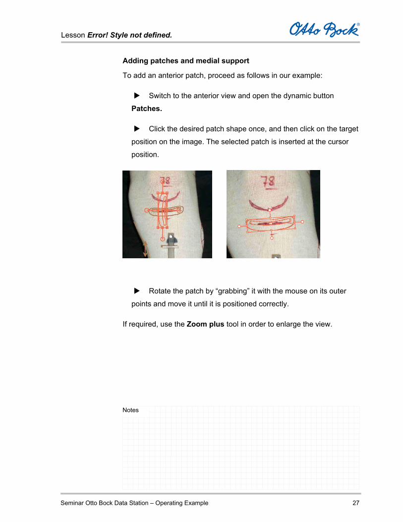
Adding patches and medial support
To add an anterior patch, proceed as follows in our example:
Switch to the anterior view and open the dynamic button
Patches.
Click the desired patch shape once, and then click on the target
position on the image. The selected patch is inserted at the cursor
position.
Rotate the patch by “grabbing” it with the mouse on its outer
points and move it until it is positioned correctly.
If required, use the Zoom plus tool in order to enlarge the view.

Lesson Error! Style not defined.
Seminar Otto Bock Data Station – Operating Example 28
Notes
To set the medial support, proceed as follows in our example:
Switch to the anterior view and open the dynamic button Medial support.
In the anterior view, use the mouse to drag the side arrows of
the medial support and thus bring it into the correct vertical position.
You can set the thickness of the medial support with the slide
control on the dynamic button.

Lesson Error! Style not defined.
Seminar Otto Bock Data Station – Operating Example 29
Notes
Entries in the Socket View tab
In the Socket View tab, the generated socket is displayed in three
dimensions and can be viewed from all sides.
To do so, use the signpost and the tool bar.
Symbol Tools
Select
Rotate in three dimensions
Move
Zoom in
Zoom out
Original size (optimal display)

Lesson Error! Style not defined.
Seminar Otto Bock Data Station – Operating Example 30
Notes
In addition to the visualization functions, the following functions are
available to you to edit the socket:
Medial radius of the condyle socket
Proximal ML measurement
Proximal reduction
Socket length
Distal reduction
Medial support
Posterior patch
Base plate liner
You will see a dynamic button for each of these functions, which you
can show and hide using the triangle symbol.

Lesson Error! Style not defined.
Seminar Otto Bock Data Station – Operating Example 31
Notes
You open the individual buttons by clicking them; they contain:
A slide control to set the respective measurement
An Original Value button to return to the default setting
A button that displays the Ideal View for the respective
measurement
The respective measurement is shown as a red line on the socket in the
socket view. Changes to the measurements are also displayed on the
three-dimensional model.
Lesson Error! Style not defined.
Seminar Otto Bock Data Station – Operating Example 32
Notes
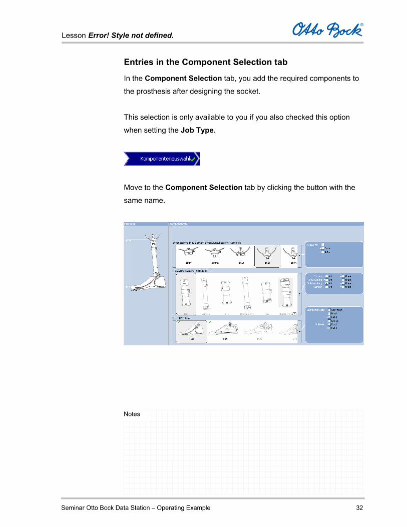
Entries in the Component Selection tab
In the Component Selection tab, you add the required components to
the prosthesis after designing the socket.
This selection is only available to you if you also checked this option
when setting the Job Type.
Move to the Component Selection tab by clicking the button with the
same name.
Lesson Error! Style not defined.
Seminar Otto Bock Data Station – Operating Example 33
Notes
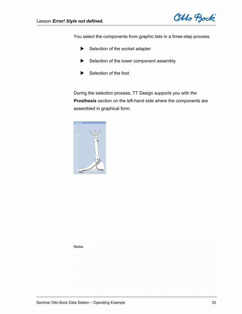
You select the components from graphic lists in a three-step process.
Selection of the socket adapter
Selection of the lower component assembly
Selection of the foot
During the selection process, TT Design supports you with the
Prosthesis section on the left-hand side where the components are
assembled in graphical form.

Lesson Error! Style not defined.
Seminar Otto Bock Data Station – Operating Example 34
Notes
Make the following selections in the three rows:
Your work in the Component Selection tab is complete when:
You have selected a component from each of the three rows
according to your requirements.
The measurements are displayed in the schematic
representation of the prosthesis on the left-hand side and the values
are acceptable to you.
After component selection is complete, move to the Order tab by
clicking the corresponding button.

Lesson Error! Style not defined.
Seminar Otto Bock Data Station – Operating Example 35
Notes
Submitting the purchase order
After you are done processing the job in the TT Design
application, switch to the Purchase Order tab by clicking the
Purchase Order button.
Here you will see an order list of the configured components; you
can activate / deactivate the individual components by selecting
or deselecting the check box next to the component.
Components with a quantity of 0 are automatically deselected.
Check the order list and change quantities or deselect
unneeded components as required.
Lesson Error! Style not defined.
Seminar Otto Bock Data Station – Operating Example 36
Notes
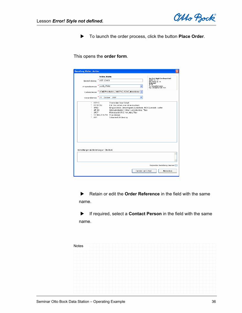
To launch the order process, click the button Place Order.
This opens the order form.
Retain or edit the Order Reference in the field with the same
name.
If required, select a Contact Person in the field with the same
name.

Lesson Error! Style not defined.
Seminar Otto Bock Data Station – Operating Example 37
Notes
Select a Delivery Address in the field with the same name.
The delivery address from the data of your medical supply company
is stored and always available for selection here.
Select a different Ship Date or retain the date displayed.
If you also want to send your purchase order to the connected
printer, select the option Print Copy of Purchase Order.
Select Send by E-Mail. The purchase order data are
transferred to the e-mail program and can be sent out from there.
Attention You need to send out the e-mail with the purchase order data
yourself.

Lesson Error! Style not defined.
Seminar Otto Bock Data Station – Operating Example 38
Notes
Closing the Otto Bock Data Station
To close the Otto Bock Data Station, select the menu command File –
Exit or the symbol in the upper right corner of the program window.
If you have not yet saved the job data then the Otto Bock Data Station
will prompt you to do so. Therefore data cannot get lost.
The Otto Bock Data Station is closed and you are back at the Windows
XP desktop.

Lesson Error! Style not defined.
Seminar Otto Bock Data Station - Functions 1
Notes
Introduction
When working with the Otto Bock TT Design application, you go
through up to five phases, each of which has a tab in the TT Design
processing window:
Specification Selection of the shaft-specific data and entry of the patient
measurements.
Photo View
Reading two digital photos (anterior and lateral photo).
Positioning the patches for the socket that is created later.
Socket View Three-dimensional view of the calculated socket, with the option
to make corrections.
Component Selection Selection of components for the prosthesis.
Ordering Display and editing of the purchase order for the current job.

Lesson Error! Style not defined.
Seminar Otto Bock Data Station - Functions 2
Notes
How to start a job in TT Design
Before you can create a transtibial socket, you first have to
create the corresponding patient.
In the patient tree, select the patient for which you want to create
a new TT Design job by clicking it with the left mouse button.
Select the command New Job in the File menu, or use the New Job button underneath the job list of the selected patient.
The Job Type tab is displayed. Select the dynamic button
Transtibial.

Lesson Error! Style not defined.
Seminar Otto Bock Data Station - Functions 3
Notes
At this stage, you can already decide which program
components of TT Design you wish to use.
Two options are available to you.
Select the corresponding option fields.

Lesson Error! Style not defined.
Seminar Otto Bock Data Station - Functions 4
Notes
If you want to create a prosthesis socket, select Socket Design.
In the Specification tab which follows, you will be prompted to
enter the corresponding measurements.
If the socket already exists and you only require components,
choose Component Selection.
In this case, you have to classify your patient according to Otto
Bock MOBIS® in the Specification tab which follows and also
enter the length measurements required for free space
calculation and component selection.
If you are creating a prosthesis socket and then want to select
components to complete the prosthesis, select both Socket Design and Component Selection.
After you confirm your selection by clicking Next, the Specification tab
is opened in the TT Design processing window.
Enter all requested measurements here.

Lesson Error! Style not defined.
Seminar Otto Bock Data Station - Functions 5
Notes
Specification
In the Specification tab, the measurements and information required
by the software are entered corresponding to the options you selected
in the previous tab.
Thus the number of measurements required is determined by your
selections.
Provide the following information in the left-hand column of the tab:
Order number
Socket
Liner
Residual limb sock
Distal cap
Outer liner
Knee support sleeve
Valve
Mobility grade
Weight of the patient

Lesson Error! Style not defined.
Seminar Otto Bock Data Station - Functions 6
Notes
In the right-hand column measurements, select the patient’s
amputated side.
At this point, entering the correct side is not mandatory. If you do
not know the side, you can also identify and establish it during
photo processing.
If you also checked off Component Selection in the preceding
Specification tab, you have to specify the measurement from
the medial tibial plateau to the floor, the foot size, and the
effective heel height of the patient.
The residual limb measurements are calculated during processing.

Lesson Error! Style not defined.
Seminar Otto Bock Data Station - Functions 7
Notes
Entries in the left-hand column
In the left-hand column, you pre-select a few core components of the
prosthesis socket. Thus you are influencing the design of the socket
and its 3D representation in the Socket View tab.
Furthermore, your patient can be classified here according to MOBIS®
(if Component Selection was chosen).
This determines which components from the Otto Bock product portfolio
are generally available for your patient in the component selection
process which follows, before the free space calculation is carried out.
Reference – identification of the current job.
Enter a reference or number for the job. This entry is later
displayed in the job list of the patient in order to identify the job
data.
Provide additional information regarding the socket components
in the fields below.
Open and close these fields by clicking the corresponding
dynamic button.
Lesson Error! Style not defined.
Seminar Otto Bock Data Station - Functions 8
Notes
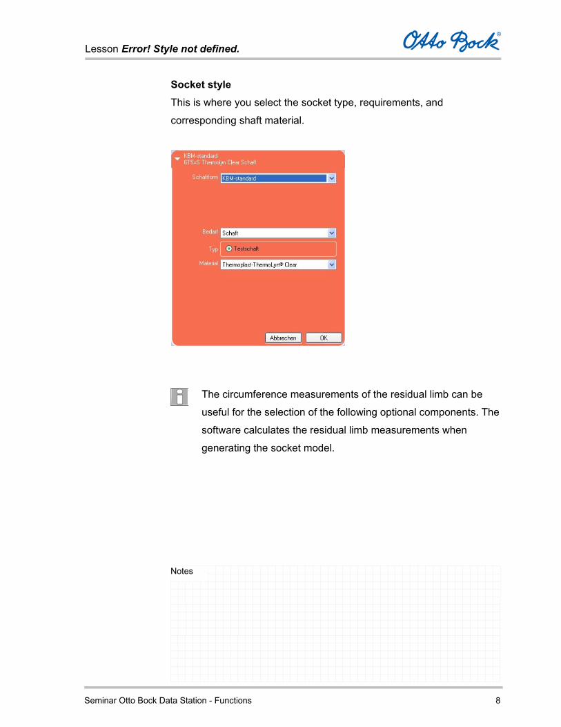
Socket style This is where you select the socket type, requirements, and
corresponding shaft material.
The circumference measurements of the residual limb can be
useful for the selection of the following optional components. The
software calculates the residual limb measurements when
generating the socket model.
Lesson Error! Style not defined.
Seminar Otto Bock Data Station - Functions 9
Notes
Therefore, it is recommended to switch to photo processing at this
point, completing that step, then switching to the three-dimensional
socket view and subsequently returning to the Specification tab.
This makes the size selection of the liner and/or residual limb sock
easier, since the circumference measurements have then been
calculated by the program and are displayed.
The program can then suggest the corresponding component sizes for
you in the form of a pre-sort.
If no photos were taken and you are not creating a socket for the patient
but only want to select components, you have to enter the
corresponding manually measured values.

Lesson Error! Style not defined.
Seminar Otto Bock Data Station - Functions 10
Notes
Liner If a liner is required, you can select the liner model, distal connection,
material, and liner size depending on the selected manufacturer.
Lesson Error! Style not defined.
Seminar Otto Bock Data Station - Functions 11
Notes
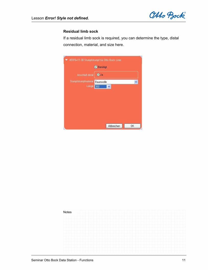
Residual limb sock If a residual limb sock is required, you can determine the type, distal
connection, material, and size here.

Lesson Error! Style not defined.
Seminar Otto Bock Data Station - Functions 12
Notes
Distal cap If a distal cap is being used, you determine the manufacturer and size
of this component here. This information is required to calculate the
socket volume.
Competitive products not included in the Otto Bock product
portfolio will not be considered on the order form.
Lesson Error! Style not defined.
Seminar Otto Bock Data Station - Functions 13
Notes
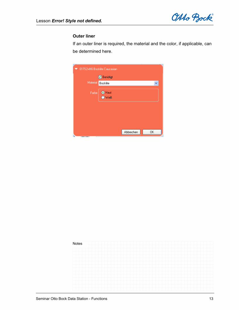
Outer liner If an outer liner is required, the material and the color, if applicable, can
be determined here.

Lesson Error! Style not defined.
Seminar Otto Bock Data Station - Functions 14
Notes
Knee support sleeve If a knee support sleeve is required, the material and the color can be
determined here.

Lesson Error! Style not defined.
Seminar Otto Bock Data Station - Functions 15
Notes
Valve If you have selected a socket with vacuum technology, the required
exhaust valve is displayed here.
Through the prior selection ‘Socket with Vacuum Technology’
under the Socket Selection button, the program offers you the
optional Harmony system in the component selection which
follows later, assuming it fits into the available free space.
The exhaust valve shown here is not required for the Harmony
system, but is intended for a conventional vacuum system.
However, it can also be deselected in the ordering process later
on if you decide on a Harmony system.
Lesson Error! Style not defined.
Seminar Otto Bock Data Station - Functions 16
Notes
Mobility grade and weight
Mobility grade Select the patient's mobility grade (grades 1 thru 4).
The selected mobility grade in conjunction with the patient weight has a
decisive influence on the functional characteristics of the prosthesis.
During the configuration of the prosthesis, only those components
which have structural and functional characteristics suitable for the
patient’s selected mobility grade and weight will be displayed.
The possible mobility grades are defined as follows:
Mobility grade 1 – Indoor walker
Mobility grade 2 – Restricted outdoor walker
Mobility grade 3 – Unrestricted outdoor walker
Mobility grade 4 – Unrestricted outdoor walker with particularly
high demands
This classification corresponds to the generally applicable
profiling questionnaire of the Medizinischer Dienst der
Spitzenverbände der Krankenkassen e.V. (MDS) (German
Registered Association of Medical Services for the National
Health Insurance Companies).

Lesson Error! Style not defined.
Seminar Otto Bock Data Station - Functions 17
Notes
Weight
Enter the patient weight. MOBIS® classifies patient weight to 75 kilograms/165 lbs, to 100 kilograms/220 lbs, to 125 kilograms/275 lbs and over 125 kilograms/275 lbs.
Both the patient weight and the selected patient mobility grade are
shown in the Otto Bock MOBIS® logo below the weight and mobility
fields.
Mobility grade 1 / patient weight <
100 kg/220 lbs
Mobility grade 4/ patient weight <
125 kg/275lbs
During processing, you receive information about the selected
mobility grade by clicking on the mortarboard symbol.
Lesson Error! Style not defined.
Seminar Otto Bock Data Station - Functions 18
Notes
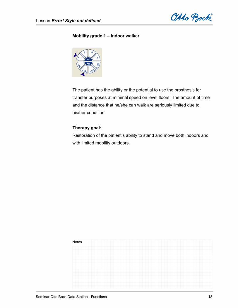
Mobility grade 1 – Indoor walker
The patient has the ability or the potential to use the prosthesis for
transfer purposes at minimal speed on level floors. The amount of time
and the distance that he/she can walk are seriously limited due to
his/her condition.
Therapy goal: Restoration of the patient’s ability to stand and move both indoors and
with limited mobility outdoors.

Lesson Error! Style not defined.
Seminar Otto Bock Data Station - Functions 19
Notes
Mobility grade 2 – Restricted outdoor walker
The patient has the ability or the potential to move slowly with the
prosthesis and can negotiate low environmental obstacles like curbs,
single steps or uneven ground. The amount of time and the distance
that he/she can walk are limited due to his/her condition.
Therapy goal: Restoration of the ability to stand, walk and move both indoors and
outdoors without any limitations.

Lesson Error! Style not defined.
Seminar Otto Bock Data Station - Functions 20
Notes
Mobility grade 3 – Unrestricted outdoor walker
The patient has the ability or the potential to move with the prosthesis
with variable cadence and can simultaneously negotiate most
environmental barriers.
He/she also has the ability to move about open areas and can
undertake occupational, therapeutic and other activities that do not
expose the prosthesis to above-average mechanical demands.
This also includes those patients who have an increased need for
security due to secondary conditions (additional handicaps, special
living circumstances) in connection with medium to high mobility
activities. In comparison to healthy individuals, the amount of time and
the distance that he/she can walk are limited only in nonessential ways.
Therapy goal: Restoration of the ability to stand, walk and move both indoors and
outdoors without any limitations.

Lesson Error! Style not defined.
Seminar Otto Bock Data Station - Functions 21
Notes
Mobility grade 4 – Unrestricted outdoor walker with particularly high demands
The patient has the ability to move with the prosthesis in a manner
similar to the unrestricted outdoor walker.
The amount of time and the distance that he/she can walk are not
limited. Moreover, due to the high functional demands, the prosthesis
can sustain a high degree of shock, tension and torsion.
Therapy goal: Restoration of the ability to stand, walk and move both indoors and
outdoors without any limitations.
Lesson Error! Style not defined.
Seminar Otto Bock Data Station - Functions 22
Notes
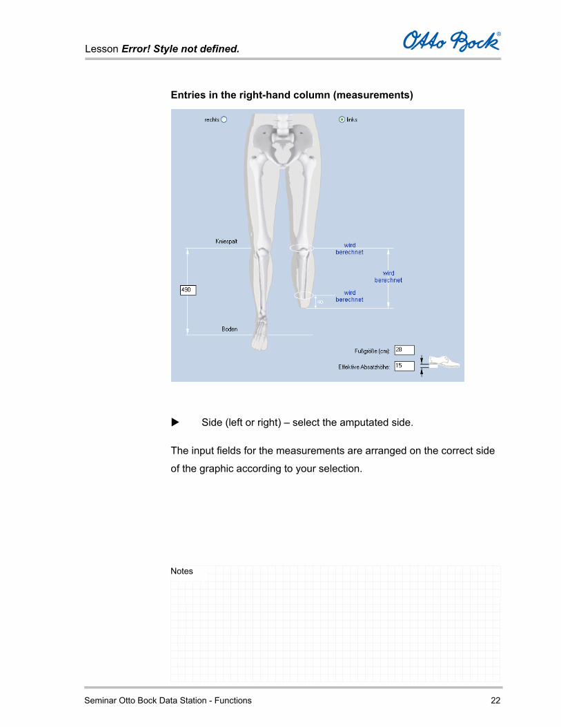
Entries in the right-hand column (measurements)
Side (left or right) – select the amputated side.
The input fields for the measurements are arranged on the correct side
of the graphic according to your selection.

Lesson Error! Style not defined.
Seminar Otto Bock Data Station - Functions 23
Notes
If you also checked off Component Selection in the preceding
Specification tab, you have to specify the measurement from
the medial tibial plateau to the floor, the foot size, and the
effective heel height of the patient.
The residual limb measurements are calculated during processing.
For the free space calculation carried out later, MPL (position
established by the photos) is assumed to be 10 mm below the medial
tibial plateau.
Measurements of the sound leg
Medial tibial plateau to the floor
The difference between the measurement from the medial tibial
plateau to the floor and the residual limb length calculated by the
software results in the amount of space available for the
Lesson Error! Style not defined.
Seminar Otto Bock Data Station - Functions 24
Notes
components.
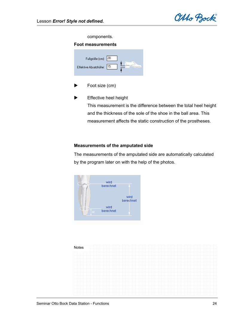
Foot measurements
Foot size (cm)
Effective heel height
This measurement is the difference between the total heel height
and the thickness of the sole of the shoe in the ball area. This
measurement affects the static construction of the prostheses.
Measurements of the amputated side
The measurements of the amputated side are automatically calculated
by the program later on with the help of the photos.
Lesson Error! Style not defined.
Seminar Otto Bock Data Station - Functions 25
Notes
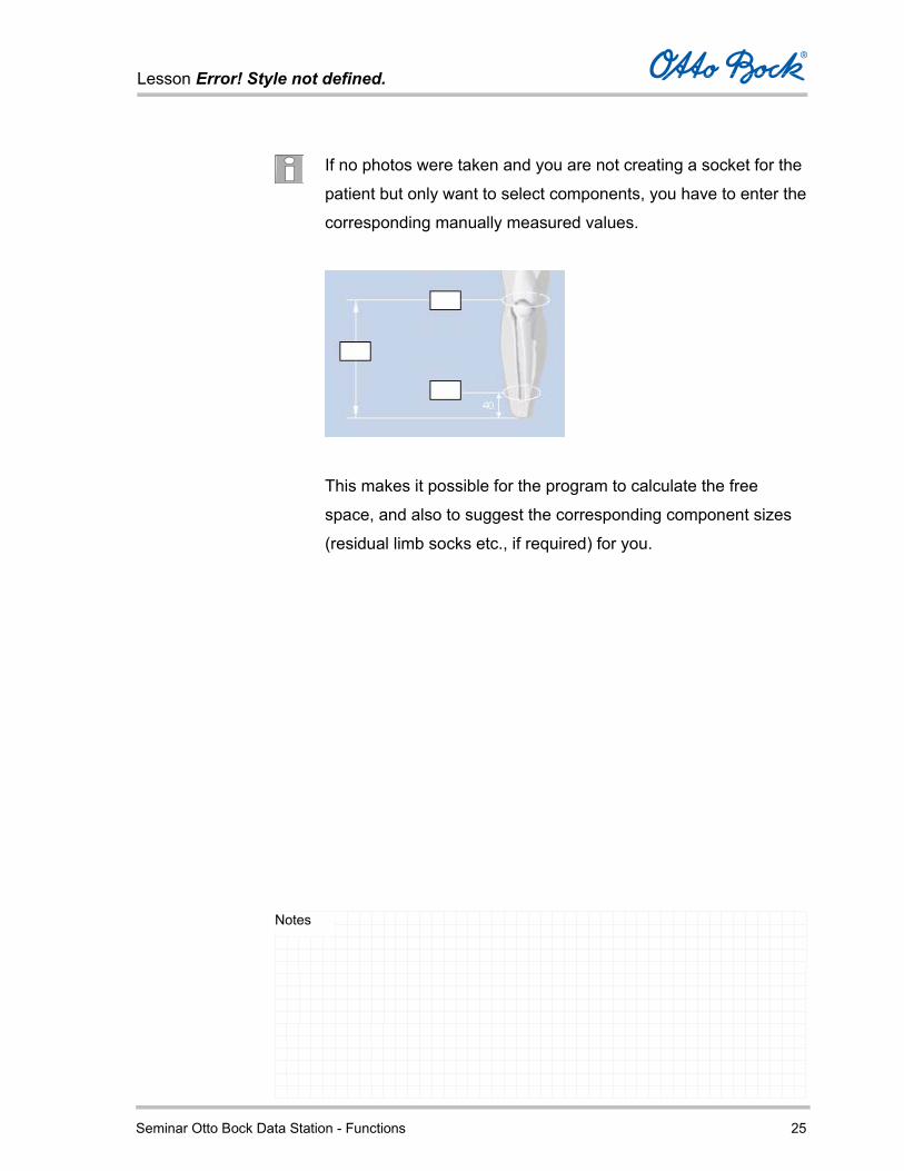
If no photos were taken and you are not creating a socket for the
patient but only want to select components, you have to enter the
corresponding manually measured values.
This makes it possible for the program to calculate the free
space, and also to suggest the corresponding component sizes
(residual limb socks etc., if required) for you.
Lesson Error! Style not defined.
Seminar Otto Bock Data Station - Functions 26
Notes
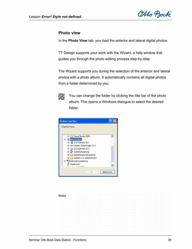
Photo view
In the Photo View tab, you load the anterior and lateral digital photos.
TT Design supports your work with the Wizard, a help window that
guides you through the photo editing process step-by-step.
The Wizard supports you during the selection of the anterior and lateral
photos with a photo album. It automatically contains all digital photos
from a folder determined by you.
You can change the folder by clicking the title bar of the photo
album. This opens a Windows dialogue to select the desired
folder.

Lesson Error! Style not defined.
Seminar Otto Bock Data Station - Functions 27
Notes
Select the drive where the digital photos are located. If you
connect the camera to your PC, it is normally recognized as a
drive and displayed in Windows Explorer. You can select this
drive.
If you have already saved the photos to a different drive on your
computer, select that drive.
Alternatively, you can create a new folder and copy the digital
photos of the lateral and anterior view to it.
The files of the existing digital photos have numbers starting with
“IMG”, e.g. “IMG_0001005”. The files have the extension “.JPG”.
The final digits of this number correspond to the consecutive
number displayed by the digital camera.

Lesson Error! Style not defined.
Seminar Otto Bock Data Station - Functions 28
Notes
With the Restart Wizard button, you can restart the Wizard at any time
while editing photos in the Photo View. The contours created up to that
point are deleted and have to be recreated.
To select the lateral and anterior photos, simply drag the
respective photo from the photo album into the corresponding
frame.
After inserting the photos, click Next.
Select the amputated side and confirm with Next.

Lesson Error! Style not defined.
Seminar Otto Bock Data Station - Functions 29
Notes
Tools in the Photo View
When marking and editing the lateral and anterior photos in the photo
view, you are supported by a tool bar with the following functions:
Symbol Tools
Select
Rotate counter-clockwise by 90°
Move
Zoom in
Zoom out
Original size
Lesson Error! Style not defined.
Seminar Otto Bock Data Station - Functions 30
Notes
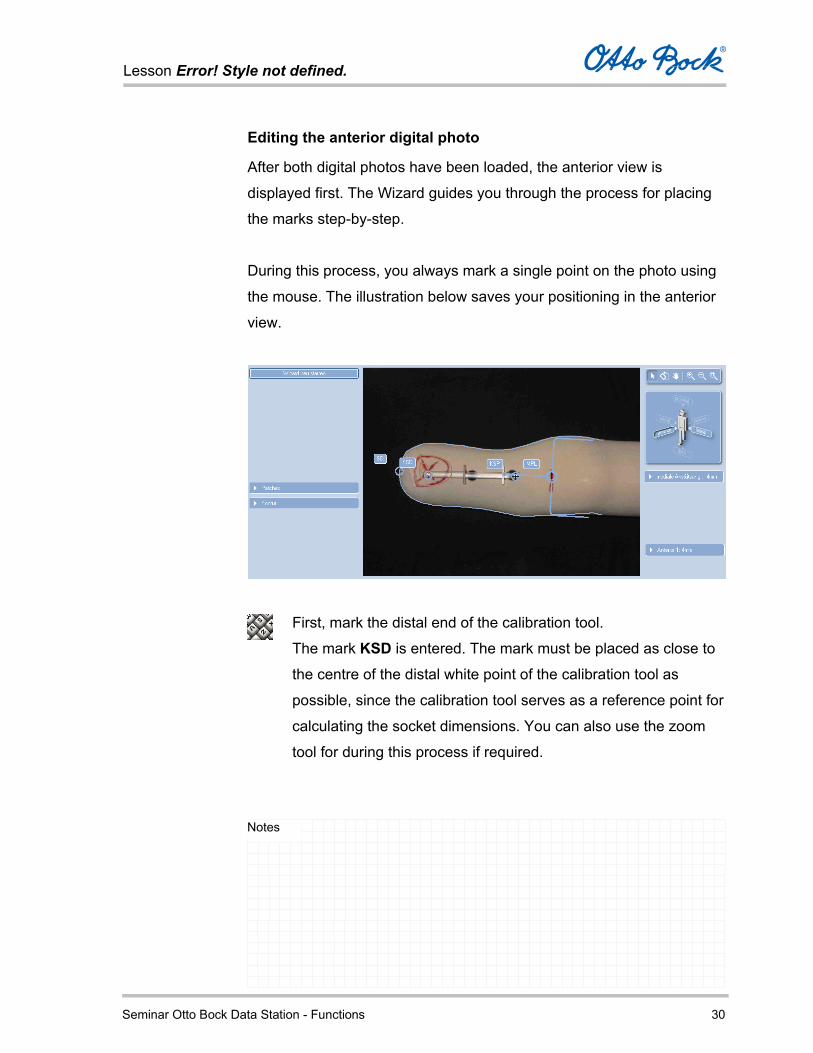
Editing the anterior digital photo
After both digital photos have been loaded, the anterior view is
displayed first. The Wizard guides you through the process for placing
the marks step-by-step.
During this process, you always mark a single point on the photo using
the mouse. The illustration below saves your positioning in the anterior
view.
First, mark the distal end of the calibration tool.
The mark KSD is entered. The mark must be placed as close to
the centre of the distal white point of the calibration tool as
possible, since the calibration tool serves as a reference point for
calculating the socket dimensions. You can also use the zoom
tool for during this process if required.

Lesson Error! Style not defined.
Seminar Otto Bock Data Station - Functions 31
Notes
Mark the proximal end of the calibration tool.
The mark KSP is entered. Once again, the mark must be placed
as close to the centre of the proximal white point of the
calibration tool as possible.
Mark the residual limb end. Ensure that the contour is actually
marked on the most distal point of the residual limb. The mark
SD is entered.
Mark the centre of the patella ligament.
The mark MPL is entered.
You can verify the positions of the individual marks.
If you have accidentally placed a mark in the wrong place, you
can use the tool on the toolbar to move it to the correct
location.
You can also correct specific marks directly after placing them,
by clicking the mark and dragging it to the desired position while
holding down the left mouse button.

Lesson Error! Style not defined.
Seminar Otto Bock Data Station - Functions 32
Notes
You now have the option of changing the orientation of the condyle
socket. The orientation calculated by the software is displayed.
You can correct the orientation of the condyle socket by clicking
the end of the displayed fork and rotating it correspondingly while
holding down the mouse button.
The axis with the condyle angle displays the orientation.
This orientation ensures that the condyle socket generated by the
reference model corresponds to the actual patient contours.
A proven method is to orient the condyle socket so that the
lateral shanks of the fork follow the lateral condyle as in the
illustration.
In order to get a feel for this tool at the outset, it may be useful to
switch back to the photo processing tab from the socket model
generated later, modify the position of the fork, and recalculate
the socket. Thus the effects quickly become obvious.

Lesson Error! Style not defined.
Seminar Otto Bock Data Station - Functions 33
Notes
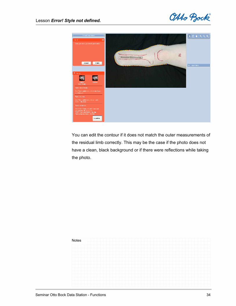
After setting the position, confirm with Next. The software calculates the anterior contour of the residual limb and
displays the contour line.
The marks from the preceding step are hidden during this
process.
Lesson Error! Style not defined.
Seminar Otto Bock Data Station - Functions 34
Notes
You can edit the contour if it does not match the outer measurements of
the residual limb correctly. This may be the case if the photo does not
have a clean, black background or if there were reflections while taking
the photo.
Lesson Error! Style not defined.
Seminar Otto Bock Data Station - Functions 35
Notes
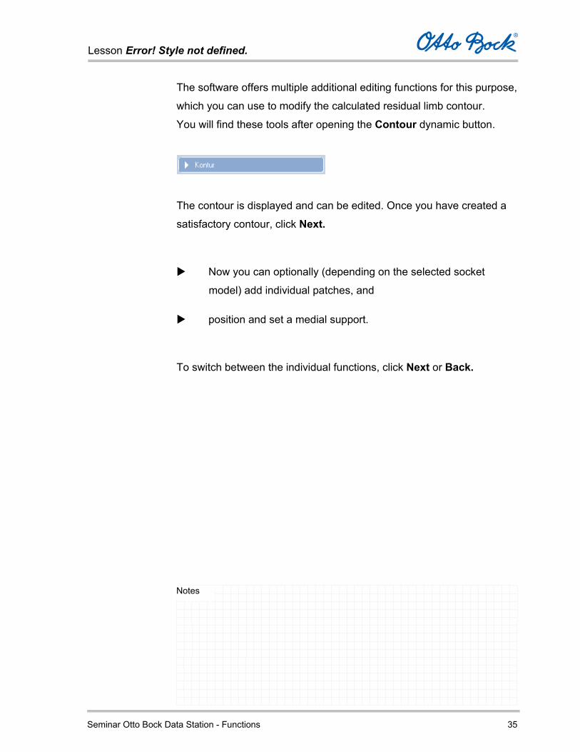
The software offers multiple additional editing functions for this purpose,
which you can use to modify the calculated residual limb contour.
You will find these tools after opening the Contour dynamic button.
The contour is displayed and can be edited. Once you have created a
satisfactory contour, click Next.
Now you can optionally (depending on the selected socket
model) add individual patches, and
position and set a medial support.
To switch between the individual functions, click Next or Back.
Lesson Error! Style not defined.
Seminar Otto Bock Data Station - Functions 36
Notes
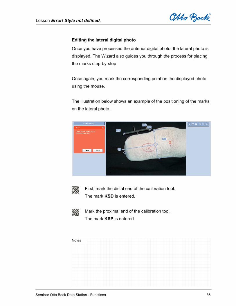
Editing the lateral digital photo
Once you have processed the anterior digital photo, the lateral photo is
displayed. The Wizard also guides you through the process for placing
the marks step-by-step
Once again, you mark the corresponding point on the displayed photo
using the mouse.
The illustration below shows an example of the positioning of the marks
on the lateral photo.
First, mark the distal end of the calibration tool.
The mark KSD is entered.
Mark the proximal end of the calibration tool.
The mark KSP is entered.

Lesson Error! Style not defined.
Seminar Otto Bock Data Station - Functions 37
Notes
Mark the residual limb end.
The mark SD is entered.
Mark the centre of the patella ligament.
The mark MPL is entered.
Mark the proximal ML height.
The mark PML is entered. The PML position depends on the
desired socket model.
In case of socket models that end approximately at the centre of
the condyle – in the area of the largest knee ML measurement –
the mark is placed at that location. In case of cross-condyle
socket models, the mark is placed at the corresponding location
above the condyle.
You can verify the positions of the individual marks.
If you have accidentally placed a mark incorrectly, you can use
the tool on the toolbar to move it to the correct location. You
can also correct specific marks directly after placing them, by
clicking the mark and dragging it to the desired position while
holding down the left mouse button.

Lesson Error! Style not defined.
Seminar Otto Bock Data Station - Functions 38
Notes
You now have the option of changing the orientation of the condyle
socket. The orientation calculated by the software is displayed.
You can correct the orientation of the condyle socket by clicking
the end of the displayed fork and rotating it correspondingly while
holding down the mouse button.
The axis with the condyle angle displays the orientation.
This orientation ensures that the condyle socket generated by the
reference model corresponds to the actual patient contours.
After setting the position, confirm with Next. The software calculates the lateral contour of the residual limb under
consideration of the marks you have entered, and displays the contour
line.
The marks from the preceding step are hidden during this
process.

Lesson Error! Style not defined.
Seminar Otto Bock Data Station - Functions 39
Notes
You can edit the contour if it does not match the outer measurements of
the residual limb correctly or if it has protrusions.
This may be the case if the photo does not have a clean, black
background or if there were reflections while taking the photo.
The software offers multiple additional editing functions for this purpose,
which you can use to modify the calculated residual limb contour.
Lesson Error! Style not defined.
Seminar Otto Bock Data Station - Functions 40
Notes
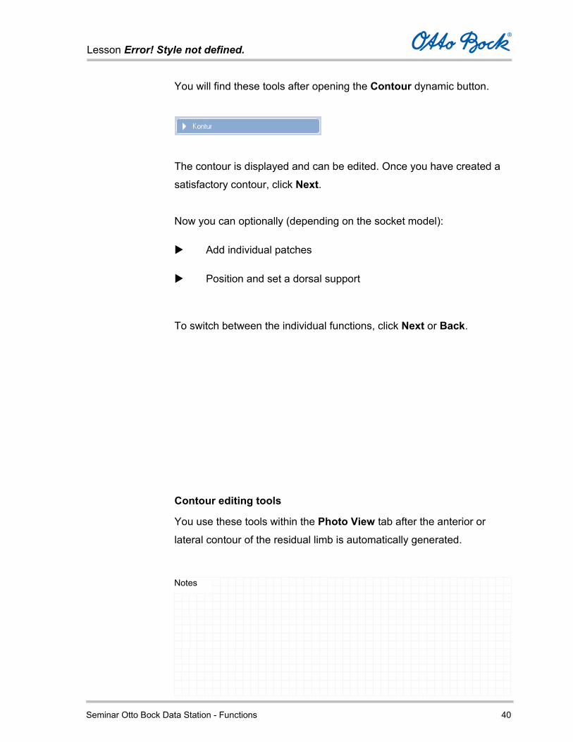
You will find these tools after opening the Contour dynamic button.
The contour is displayed and can be edited. Once you have created a
satisfactory contour, click Next.
Now you can optionally (depending on the socket model):
Add individual patches
Position and set a dorsal support
To switch between the individual functions, click Next or Back.
Contour editing tools
You use these tools within the Photo View tab after the anterior or
lateral contour of the residual limb is automatically generated.

Lesson Error! Style not defined.
Seminar Otto Bock Data Station - Functions 41
Notes
It is also possible to edit the contour of a residual limb photo that has
already been processed.
To do so, reopen the Photo View tab and select the anterior or
lateral view using the symbolic signpost.
Click on the dynamic button Contour.
Lesson Error! Style not defined.
Seminar Otto Bock Data Station - Functions 42
Notes
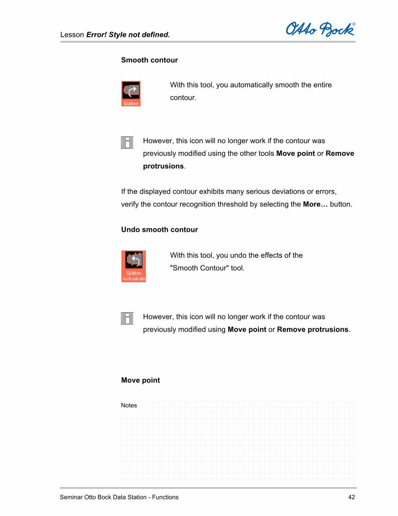
Smooth contour
However, this icon will no longer work if the contour was
previously modified using the other tools Move point or Remove protrusions.
If the displayed contour exhibits many serious deviations or errors,
verify the contour recognition threshold by selecting the More… button.
Undo smooth contour
However, this icon will no longer work if the contour was
previously modified using Move point or Remove protrusions.
Move point
With this tool, you automatically smooth the entire
contour.
With this tool, you undo the effects of the
"Smooth Contour" tool.
Lesson Error! Style not defined.
Seminar Otto Bock Data Station - Functions 43
Notes
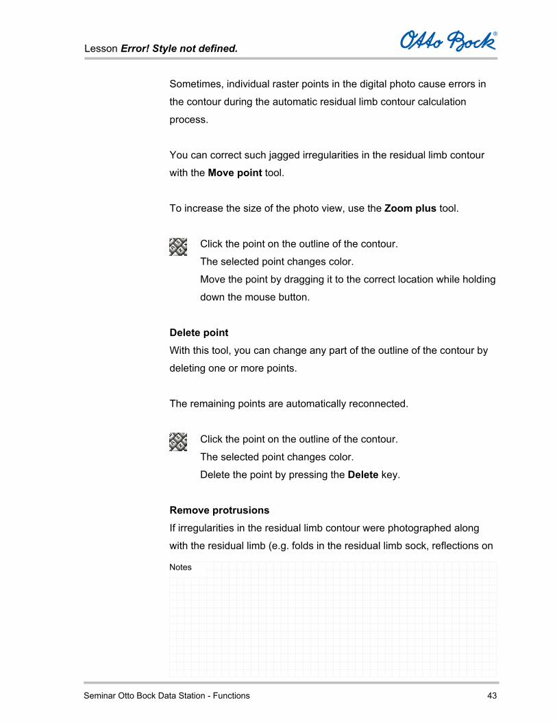
Sometimes, individual raster points in the digital photo cause errors in
the contour during the automatic residual limb contour calculation
process.
You can correct such jagged irregularities in the residual limb contour
with the Move point tool.
To increase the size of the photo view, use the Zoom plus tool.
Click the point on the outline of the contour.
The selected point changes color.
Move the point by dragging it to the correct location while holding
down the mouse button.
Delete point With this tool, you can change any part of the outline of the contour by
deleting one or more points.
The remaining points are automatically reconnected.
Click the point on the outline of the contour.
The selected point changes color.
Delete the point by pressing the Delete key.
Remove protrusions If irregularities in the residual limb contour were photographed along
with the residual limb (e.g. folds in the residual limb sock, reflections on
Lesson Error! Style not defined.
Seminar Otto Bock Data Station - Functions 44
Notes
the calibration tool), so-called protrusions can result during the
automatic residual limb contour calculation process.
You can correct such irregularities with the Remove protrusions tool.
To do so, drag the connection between two points until it is smooth,
thus removing the protrusion.
To increase the size of the photo view, use the Zoom plus tool.
Click the point on one side of the protrusion.
Now press and hold the SHIFT key and drag from the starting
point to the end point on the other side of the protrusion while
holding the mouse button.
As soon as you release the mouse button, all points between the
start point and the end point are deleted.
This creates a straight line between the two points and removes the
protrusion.
You can also delete individual points in order to straighten the contour.

Lesson Error! Style not defined.
Seminar Otto Bock Data Station - Functions 45
Notes
Contour recognition threshold With this tool, you can set the brightness level the software uses to
differentiate the pixels in the digital photo as the residual limb or
background. The setting is established using a slide control.
With Use Default Value, you can reset this setting to the default value.
The lower this value is set, the further the contour extends outwards,
since darker pixels are now also identified as part of the residual limb in
the transitional area between the residual limb and the background.
This function can be useful for underexposed photos. If the value
is set too low, a black line is visible between the residual limb
and the calculated contour; this effectively makes the socket
bigger. Errors where parts of the background or the calibration
tool are identified as part of the residual limb are also more
frequent in this case. These protrusions have to be removed with
the help of the contour editing tools.
The higher this value is set, the less far the contour extends outwards,
since lighter pixels in the transitional area between the residual limb and
the background are located closer to the centre of the residual limb.

Lesson Error! Style not defined.
Seminar Otto Bock Data Station - Functions 46
Notes
For overexposed photos, raising the brightness level can be useful.
If the value is set too high, the contour recognized by the program is
located within the residual limb. In this case, the contour is frequently
very irregular and does not follow the shape of the residual limb.
Medial support After displaying and optionally editing the anterior contour of the
residual limb, you can establish the position and thickness of the medial
support using the mouse.
To increase the size of the photo view, use the Zoom plus tool.
To do so, drag the line with the three symbolic double arrows to
the desired position.

Lesson Error! Style not defined.
Seminar Otto Bock Data Station - Functions 47
Notes
The two outer double arrows define the edges of the patch; the centre
double arrow shows the position of the lowest point. This position does
not necessarily have to be at the centre of the patch; it can also be
moved.
By opening the dynamic button Medial Support, you can
establish the thickness of the support. The default value is 3 mm.
Adding patches
While editing the image in the Photo View tab, you can insert one or
more so-called patches in the anterior and lateral views; patches are
applied to the socket model at the location of bony protrusions or scars.
This affects the most prominent point of the area being built up or
reduced.
Anterior and lateral patch types are available for you to select and edit
in the Photo View tab.
You can also add a patch at any time later after photo editing is
complete. To do so, switch to the anterior or lateral photo view
using the symbolic signpost, and open the dynamic button
Patches.

Lesson Error! Style not defined.
Seminar Otto Bock Data Station - Functions 48
Notes
Anterior patches
The patch types displayed here are available for socket editing in the
anterior view.
Lesson Error! Style not defined.
Seminar Otto Bock Data Station - Functions 49
Notes
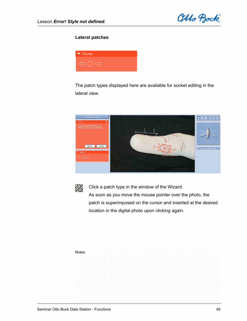
Lateral patches
The patch types displayed here are available for socket editing in the
lateral view.
Click a patch type in the window of the Wizard.
As soon as you move the mouse pointer over the photo, the
patch is superimposed on the cursor and inserted at the desired
location in the digital photo upon clicking again.

Lesson Error! Style not defined.
Seminar Otto Bock Data Station - Functions 50
Notes
The name of the button corresponds to the residual limb view
(anterior / lateral) and a number (e.g. Anterior 1). The number
corresponds to the sequence in which the patches are inserted.
When a patch is deleted, the numbers are automatically updated.
Such a dynamic button is available for every patch on the socket.
Once you have correctly shaped and positioned all required patches,
confirm with Next.
As soon as a patch has been positioned on
the photo, you will find a
corresponding dynamic button on the right-
hand side of the editing window; the depth
of the patch can be individually adapted.
You can adapt the position, size, and
shape of the patch by dragging
the individual points.

Lesson Error! Style not defined.
Seminar Otto Bock Data Station - Functions 51
Notes
Socket View
In the Socket View tab, the socket calculated based on the data you
have entered is displayed in three dimensions.
You can view the socket from all sides and rotate it freely in space by
dragging it with the mouse.
When you first open the Socket View tab, three-dimensional
rotation is activated by default.

Lesson Error! Style not defined.
Seminar Otto Bock Data Station - Functions 52
Notes
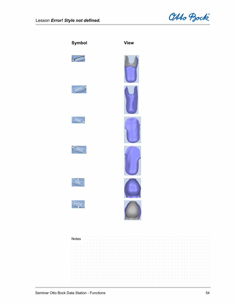
Symbolic Guide
Select the various socket views using the symbolic guide in the top right
corner of the screen.
You can modify the display size (zoom) of the socket by clicking the
right mouse button and dragging with the mouse.
Use this button in the top left corner of the screen to display or
hide the individual functions for editing the socket.
Lesson Error! Style not defined.
Seminar Otto Bock Data Station - Functions 53
Notes
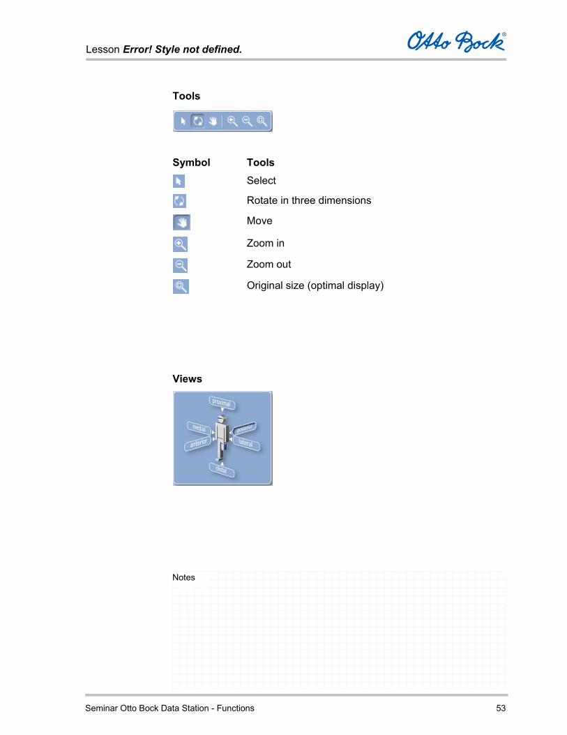
Tools
Symbol Tools
Select
Rotate in three dimensions
Move
Zoom in
Zoom out
Original size (optimal display)
Views
Lesson Error! Style not defined.
Seminar Otto Bock Data Station - Functions 54
Notes
Symbol View
Lesson Error! Style not defined.
Seminar Otto Bock Data Station - Functions 55
Notes
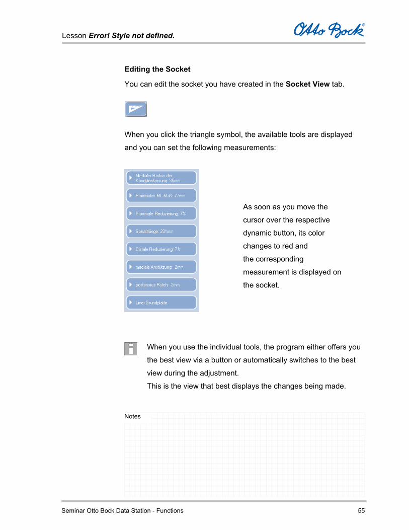
Editing the Socket
You can edit the socket you have created in the Socket View tab.
When you click the triangle symbol, the available tools are displayed
and you can set the following measurements:
When you use the individual tools, the program either offers you
the best view via a button or automatically switches to the best
view during the adjustment.
This is the view that best displays the changes being made.
As soon as you move the
cursor over the respective
dynamic button, its color
changes to red and
the corresponding
measurement is displayed on
the socket.

Lesson Error! Style not defined.
Seminar Otto Bock Data Station - Functions 56
Notes
Medial radius of the condyle socket
To edit the medial radius of the condyle socket, select the
dynamic button shown above. The current value is displayed on
the button.
In addition to changing the value with a slide control, you can set the
socket view to anterior.
The changes to the dimensions are best displayed in this view.
With Original Values, you undo your changes and reset to the
original values.
Clicking on the top of the handle closes it.

Lesson Error! Style not defined.
Seminar Otto Bock Data Station - Functions 57
Notes
Proximal ML measurement
To edit the proximal ML dimension, select the dynamic button
shown above. The current value is displayed on the button.
In addition to changing the value with a slide control, you can set the
socket view to anterior.
The changes to the dimensions are best displayed in this view.
With Original Values, you undo your changes and reset to the
original values.
Clicking on the top of the handle closes it.

Lesson Error! Style not defined.
Seminar Otto Bock Data Station - Functions 58
Notes
Proximal reduction
To edit the proximal reduction, select the dynamic button shown
above. The current value is displayed on the button.
In addition to changing the value with a slide control, you can set the
socket view to anterior.
The changes to the dimensions are best displayed in this view.
With Original Values, you undo your changes and reset to the
original values.
Clicking on the top of the handle closes it.
Lesson Error! Style not defined.
Seminar Otto Bock Data Station - Functions 59
Notes
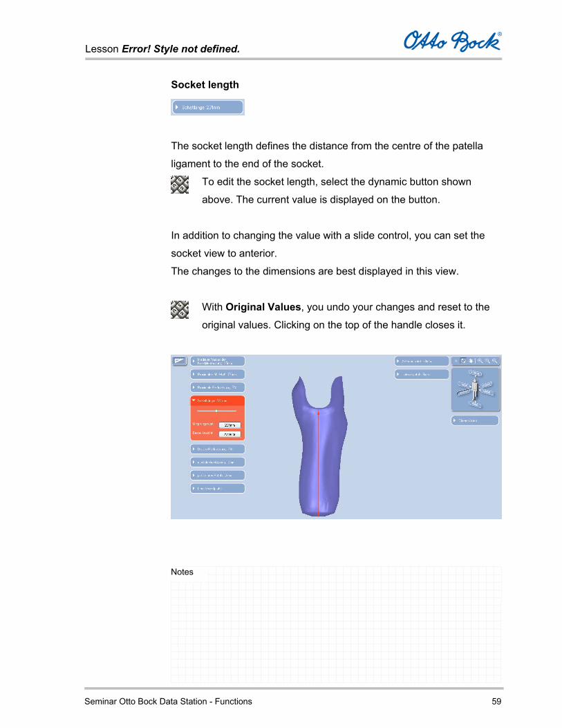
Socket length
The socket length defines the distance from the centre of the patella
ligament to the end of the socket.
To edit the socket length, select the dynamic button shown
above. The current value is displayed on the button.
In addition to changing the value with a slide control, you can set the
socket view to anterior.
The changes to the dimensions are best displayed in this view.
With Original Values, you undo your changes and reset to the
original values. Clicking on the top of the handle closes it.
Lesson Error! Style not defined.
Seminar Otto Bock Data Station - Functions 60
Notes
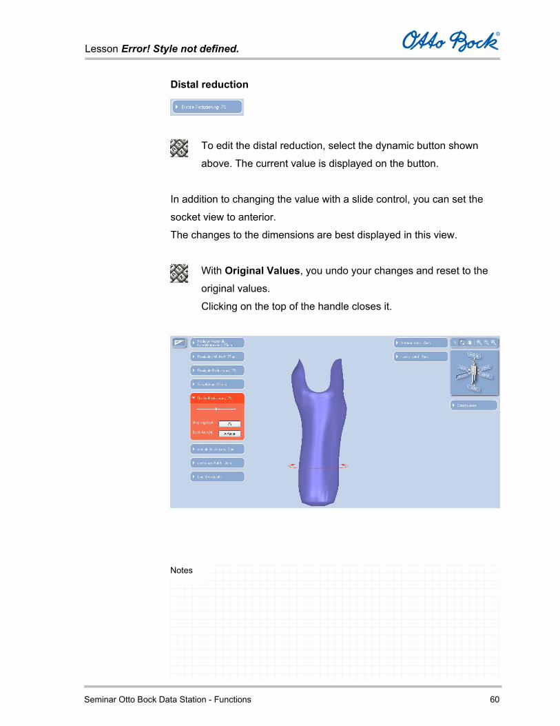
Distal reduction
To edit the distal reduction, select the dynamic button shown
above. The current value is displayed on the button.
In addition to changing the value with a slide control, you can set the
socket view to anterior.
The changes to the dimensions are best displayed in this view.
With Original Values, you undo your changes and reset to the
original values.
Clicking on the top of the handle closes it.

Lesson Error! Style not defined.
Seminar Otto Bock Data Station - Functions 61
Notes
Base plate liner
If you selected a liner that has a fixed base plate, this dynamic
button is displayed. Thus the orientation of the plate can be
edited if required.
You can modify three parameters:
Angle
Displacement in the sagittal plane: Posterior – anterior
Displacement in the frontal plane: Medial – lateral

Lesson Error! Style not defined.
Seminar Otto Bock Data Station - Functions 62
Notes
Every time a parameter is changed using the corresponding slide
control, the program automatically displays the corresponding socket
view. The changes to the dimensions are best displayed in this view.
Clicking on the top of the handle closes the tool.

Lesson Error! Style not defined.
Seminar Otto Bock Data Station - Functions 63
Notes
Medial support
To edit the medial support parameters, select the dynamic button
shown above. The current value is displayed on the button.
In principle, this function corresponds to the medial support
positioning function in the photo view of the anterior image.
Here you receive a better overview of the medial support position
due to the three-dimensional socket view.
Lesson Error! Style not defined.
Seminar Otto Bock Data Station - Functions 64
Notes
In addition to changing the value with a slide control, you can set the
socket view to anterior.
The changes to the dimensions are best displayed in this view.
With Original Values, you undo your changes and reset to the
original values.
Clicking on the top of the handle closes the tool.

Lesson Error! Style not defined.
Seminar Otto Bock Data Station - Functions 65
Notes
Posterior patch
To edit the posterior patch parameters, select the dynamic button
shown above. The current value is displayed on the button.
In addition to changing the value with a slide control, you can set the
socket view to lateral.
The changes to the dimensions are best displayed in this view.
With Original Values, you undo your changes and reset to the
original values.
Clicking on the top of the handle closes the tool.
Lesson Error! Style not defined.
Seminar Otto Bock Data Station - Functions 66
Notes
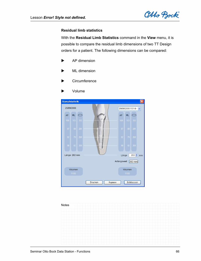
Residual limb statistics
With the Residual Limb Statistics command in the View menu, it is
possible to compare the residual limb dimensions of two TT Design
orders for a patient. The following dimensions can be compared:
AP dimension
ML dimension
Circumference
Volume
Lesson Error! Style not defined.
Seminar Otto Bock Data Station - Functions 67
Notes
After opening the residual limb statistics window, the left-hand side of
the window initially displays the values for the current job.
To compare these values with another job for the same patient,
you can select another job by date or reference in the selection
field at the top right.
The values for the comparative job are then displayed on the right-hand
side of the window.
Reconciling the residual limb length Before comparing the residual limb dimensions of two orders for a
patient, the residual limb length must first be reconciled to the same
value so that a realistic comparison is possible.
Differences in the length measurements are unavoidable due to
small discrepancies when the positioning the MPT (‘Mid Patella
Tendon’) mark.
The volume of the two residual limbs can only be compared if the
residual limb lengths are reconciled manually.
Lesson Error! Style not defined.
Seminar Otto Bock Data Station - Functions 68
Notes
Read the corresponding length of the residual limb from the
current values on the left-hand side and enter the same value in
the Length field on the right-hand side.
The button Original Value located below displays the original
residual limb length of the second job and resets it when the
button is clicked.
You can view the volumes of the two residual limbs in the Volume
fields.
With Print, you can send the residual limb statistics data to the
connected Windows printer.
With Copy, you can store the residual limb statistics data on the
Windows clipboard.
With Ctrl+V, you can paste these data into another program, e.g.
a word processor, for further editing.
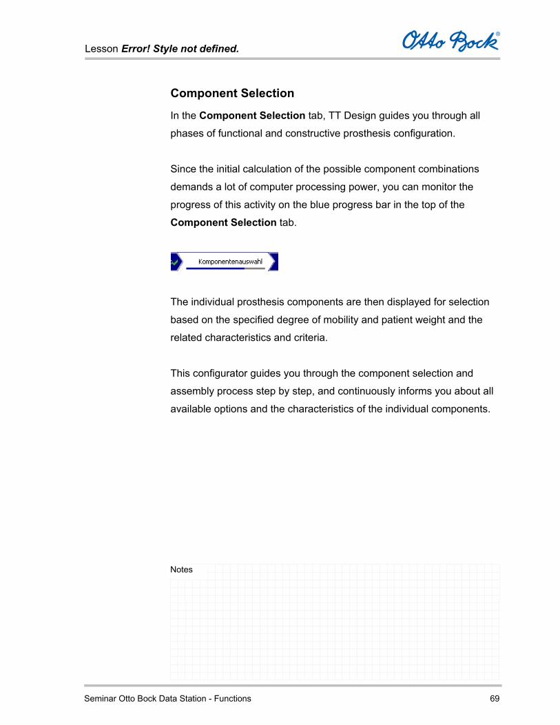
Lesson Error! Style not defined.
Seminar Otto Bock Data Station - Functions 69
Notes
Component Selection
In the Component Selection tab, TT Design guides you through all
phases of functional and constructive prosthesis configuration.
Since the initial calculation of the possible component combinations
demands a lot of computer processing power, you can monitor the
progress of this activity on the blue progress bar in the top of the
Component Selection tab.
The individual prosthesis components are then displayed for selection
based on the specified degree of mobility and patient weight and the
related characteristics and criteria.
This configurator guides you through the component selection and
assembly process step by step, and continuously informs you about all
available options and the characteristics of the individual components.

Lesson Error! Style not defined.
Seminar Otto Bock Data Station - Functions 70
Notes
The functions in the Component Selection tab are only available
if you chose the Component Selection option in the Job Type
tab.
After component selection is complete, you move to the Order tab.
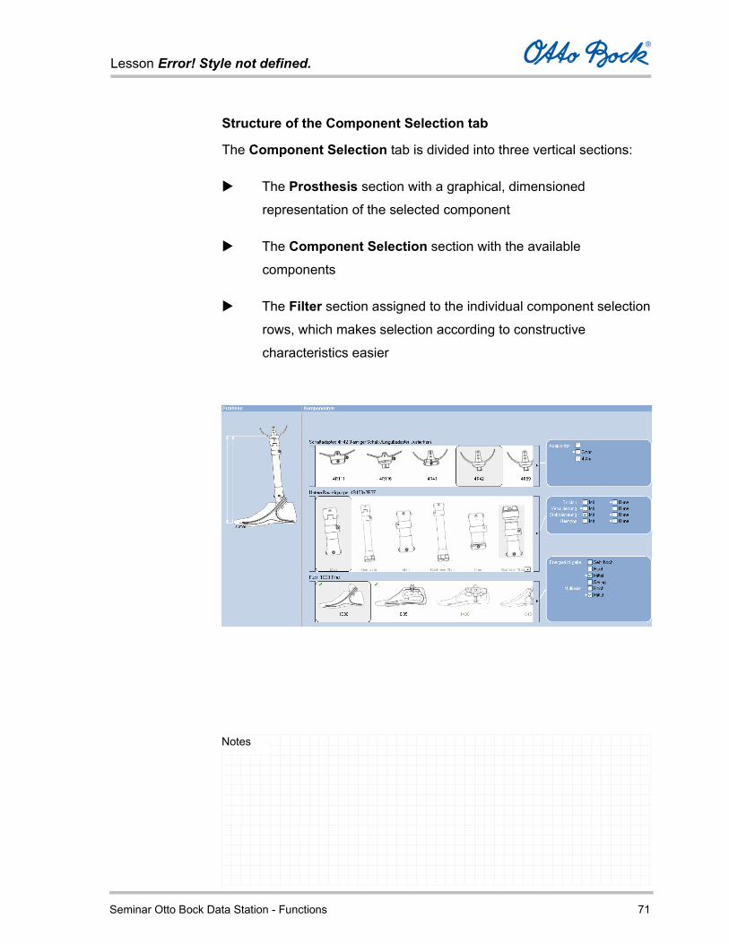
Lesson Error! Style not defined.
Seminar Otto Bock Data Station - Functions 71
Notes
Structure of the Component Selection tab
The Component Selection tab is divided into three vertical sections:
The Prosthesis section with a graphical, dimensioned
representation of the selected component
The Component Selection section with the available
components
The Filter section assigned to the individual component selection
rows, which makes selection according to constructive
characteristics easier

Lesson Error! Style not defined.
Seminar Otto Bock Data Station - Functions 72
Notes
Prosthesis section
In the Prosthesis section on the left-hand side,
you can see a graphical representation of the
assembled selected components.
This is where you see the current, still
incomplete or later also complete,
schematically assembled prosthesis.
The components you select in the Component Selection section are
inserted into this column.
The configured prosthesis is assembled graphically, step by step.
The graphical information shows the progress of the selection process
and permits visual verification of the components used.
As soon as the prosthesis is fully configured, the program calculates the
free space.
A dimension of ± 0 shows that the selected components fit into
the available free space and that an adjustment to the required
overall prosthesis length is possible.
Component Selection section

Lesson Error! Style not defined.
Seminar Otto Bock Data Station - Functions 73
Notes
In the Component Selection section in the center, you select
the individual components - which are displayed graphically -
simply by clicking the illustration of the desired component.
The available components are displayed at the appropriate level of the
prosthesis schematic shown on the left-hand side.

Lesson Error! Style not defined.
Seminar Otto Bock Data Station - Functions 74
Notes
The available components are divided into rows according to the
installation location within the prosthesis, from top to bottom:
Socket adapters
Component assemblies
Foot
The individual components can be selected by clicking them with
the mouse, and are then inserted into the schematic
representation of the prosthesis shown on the left-hand side. If a
component from that group has already been inserted, it is
replaced and the new component is shown.
In order to display information about a component, hold the
mouse pointer over the component briefly. Descriptive text for the
respective component is displayed. Use these texts to help you
make decisions during component selection.

Lesson Error! Style not defined.
Seminar Otto Bock Data Station - Functions 75
Notes
Components that do not fit into the available free space due to their
structural height in combination with the previously selected
components are displayed with a double arrow. This applies to
component combinations that are too long as well as those that are too
short.
If you select such a component that is identified with an orange
double arrow, it is still displayed in the schematic representation
of the prosthesis shown on the left-hand side.
At the same time, the previously selected component that requires too
much space in combination with the new component is deselected and
is itself shown with an orange double arrow in order to identify the
space issue.
If more components are available than can be displayed in a row,
you can use the arrows on the sides to scroll left and right.

Lesson Error! Style not defined.
Seminar Otto Bock Data Station - Functions 76
Notes
As soon as you complete a row by selecting a compatible component,
the color of the corresponding filter changes from red to blue. A red filter
box indicates that a component selection has not yet been made on the
corresponding row.
Filter section In the right-hand Filter section, characteristics for the individual
components can be selected. These characteristics correspond to the
characteristics or construction of the components.
When the Component Selection tab is first opened, no characteristics
are selected.
If there is a large range of choices in the type and construction of
a component, you can select the desired characteristics in the
filter section.

Lesson Error! Style not defined.
Seminar Otto Bock Data Station - Functions 77
Notes
The components that correspond to the selected criteria are
automatically moved to the left side of the component row and identified
with green checkmarks.
The sequence of the components within a row is determined by
the MOBIS® system; the components are listed in ascending
order by the degree of mobility and allowable patient weight (see
Otto Bock System Overview for Modular Leg Prostheses in the
catalogue).
This also applies if the sequence was modified through the use
of filters. In this case, the selected components displayed at the
left are shown in the corresponding MOBIS sequence within that
sub-group.
You can identify the characteristics of a selected component at a

Lesson Error! Style not defined.
Seminar Otto Bock Data Station - Functions 78
Notes
glance by looking at the small white dots within the
corresponding filter section. These show the assignment of the
component within the filter criteria.
Your work in the Component Selection tab is complete when:
You have selected a component from each of the five rows
according to your requirements.
The measurements are displayed in the schematic
representation of the prosthesis on the left-hand side and the
values are acceptable to you.
After component selection is complete, move to the Order tab by
clicking the button with the same name.
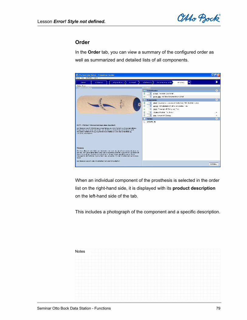
Lesson Error! Style not defined.
Seminar Otto Bock Data Station - Functions 79
Notes
Order
In the Order tab, you can view a summary of the configured order as
well as summarized and detailed lists of all components.
When an individual component of the prosthesis is selected in the order
list on the right-hand side, it is displayed with its product description
on the left-hand side of the tab.
This includes a photograph of the component and a specific description.

Lesson Error! Style not defined.
Seminar Otto Bock Data Station - Functions 80
Notes
The Order tab contains the order list on the right-hand side, which lists
the item numbers, descriptions, and order quantities.
You can set the quantity for each component in the order list.
If you do not need an individual component, you an deselect it by
changing the quantity to zero.
This allows you to avoid reordering components you may already
have in stock. On the other hand, you can order certain
components in larger quantities, for example to stock them as
replacement parts.

Lesson Error! Style not defined.
Seminar Otto Bock Data Station - Functions 81
Notes
To place the order with Otto Bock, click the Order button.

Lesson Error! Style not defined.
Seminar Otto Bock Data Station - Functions 82
Notes
This opens the Order form, where you can complete the following
information:
Order reference
Enter an order reference. By default, the field displays the order
reference entered at the outset.
Contact person
You can select a contact person here.
The data for the list of contact persons can be maintained in the
tab Addresses/Personnel of the option dialog (menu command
Tools – Options…).
Shipping address
You can select an alternative shipping address here.
The data for the list of shipping addresses can be maintained in
the Addresses/ Personnel tab (menu command Tools – Options).
Selection of the shipping date (depends on regional settings).
With the help of the calendar, you can select the desired
shipping date.
No partial delivery – depends on regional settings. If you check
this field, the order will only be sent as a complete delivery. The
order will not be sent until all parts are available.
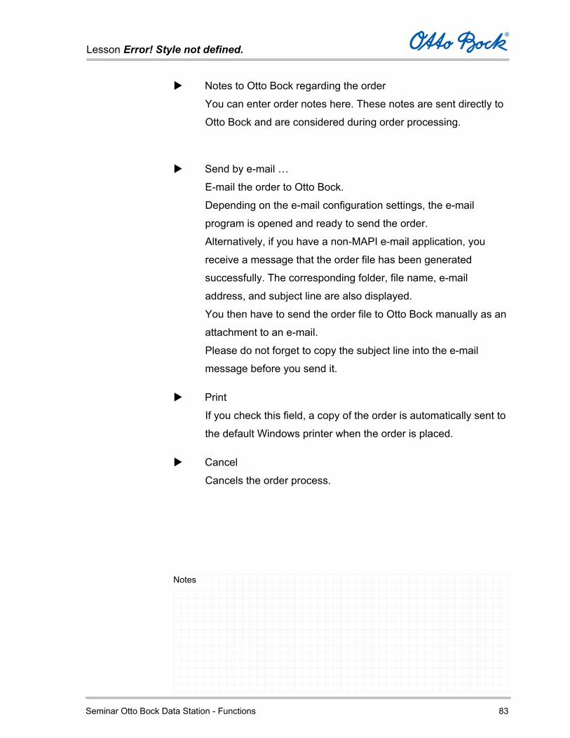
Lesson Error! Style not defined.
Seminar Otto Bock Data Station - Functions 83
Notes
Notes to Otto Bock regarding the order
You can enter order notes here. These notes are sent directly to
Otto Bock and are considered during order processing.
Send by e-mail …
E-mail the order to Otto Bock.
Depending on the e-mail configuration settings, the e-mail
program is opened and ready to send the order.
Alternatively, if you have a non-MAPI e-mail application, you
receive a message that the order file has been generated
successfully. The corresponding folder, file name, e-mail
address, and subject line are also displayed.
You then have to send the order file to Otto Bock manually as an
attachment to an e-mail.
Please do not forget to copy the subject line into the e-mail
message before you send it.
If you check this field, a copy of the order is automatically sent to
the default Windows printer when the order is placed.
Cancel
Cancels the order process.