our product range - sensor technology, signal processing ... · sensors in detail 07 ......
TRANSCRIPT
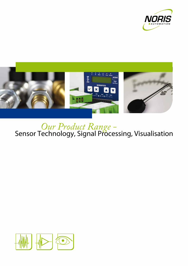
Our Product Range - Sensor Technology, Signal Processing, Visualisation
Content
Aim for success - with NORIS 03
We supply everything from one source 04
SENSORS in detail 07
Speed sensors (non-contacting) 08
Temperature sensors 10
Cable harnesses 12
Speed pick-ups (mech. connected) 14
Pressure transducers 15
Rotation angle pick-ups 16
Tachogenerators 17
SIGNAL PROCESSING in detail 19
Measuring transducers and limit value switches 20
Multifunctional devices 22
VISUALISATION in detail 25
Analogue indicators 26
Aim for success -with NORIS
For us reliability is keyOur products are designed to reliably operate for years and years under the most
extreme environmental conditions in safety applications. We constantly ask ourselves
the question: „What is REALLY required in order to offer our customers the functions
they really need?“
Through a large number of projects in the most diverse sectors we have been able to
proof that:
Our sophisticated products and concepts have a proven record or success under
extreme conditions in numerous applications
We know what our customers really need
Our well-established delivery loyalty and reliable service provide our customers with
the support they expect (in many cases more than 30 years)
Individual solutions of the highest quality do not need to be costly
Reliability and trust founded on almost 90 years of experienceWe‘ve been there from the very beginning. Experience is our greatest asset. For almost
90 years we have been successfully developing products and solutions in the fields of
sensor technology, signal processing and visualisation. We leave nothing to chance –
that‘s why our in-company development and production ensures everything comes
from under one roof.
Reap the profits from our greatest asset:
Comprehensive customer support based on long-standing cooperation
Experienced staff and their quality awareness
Perfect service worldwide
DIN EN ISO 9001:2008 certified quality and transparency
We offer complete solutionsWe take a holistic approach in solving your specific tasks. Even as early as the design
stage our products are developed to perfectly complement each other. This gives rise
to a module concept on system level that enables us to create complete measurement
and signal chains from our products. Furthermore, even after your purchase we stay
involved in your project by supplying spare parts as required as well as updating and
expanding your system solution.
Your benefits at a glance:
Maximum product compatibility and flexibility
Cost-effective solutions based on a modular system
Reliability ensured by perfectly matched components
Guaranteed availability of devices and spare parts over many years
Our areas of expertiseOur customers mainly come from ship-
building, transport technology, mecha-
nical engineering and industry. You will
find our products and solutions in motors,
engines, gearboxes, devices and machi-
nes worldwide.
We would like to include you among our
many satisfied customers!
Shipbuilding
Railway industries
Industry
Machinery and equipment
Commercial vehicles
Your future is our futureTo offer state-of-the-art products fea-
turing ultramodern technology at fair and
attractive prices now and in the future,
we constantly strive to:
Integrate the latest technologies in
our products
Test new developments under the
toughest conditions
Create individual solutions for our
customers
Focus on the ever growing demands
when developing new devices
Be one step ahead of currently
applicable standards
03
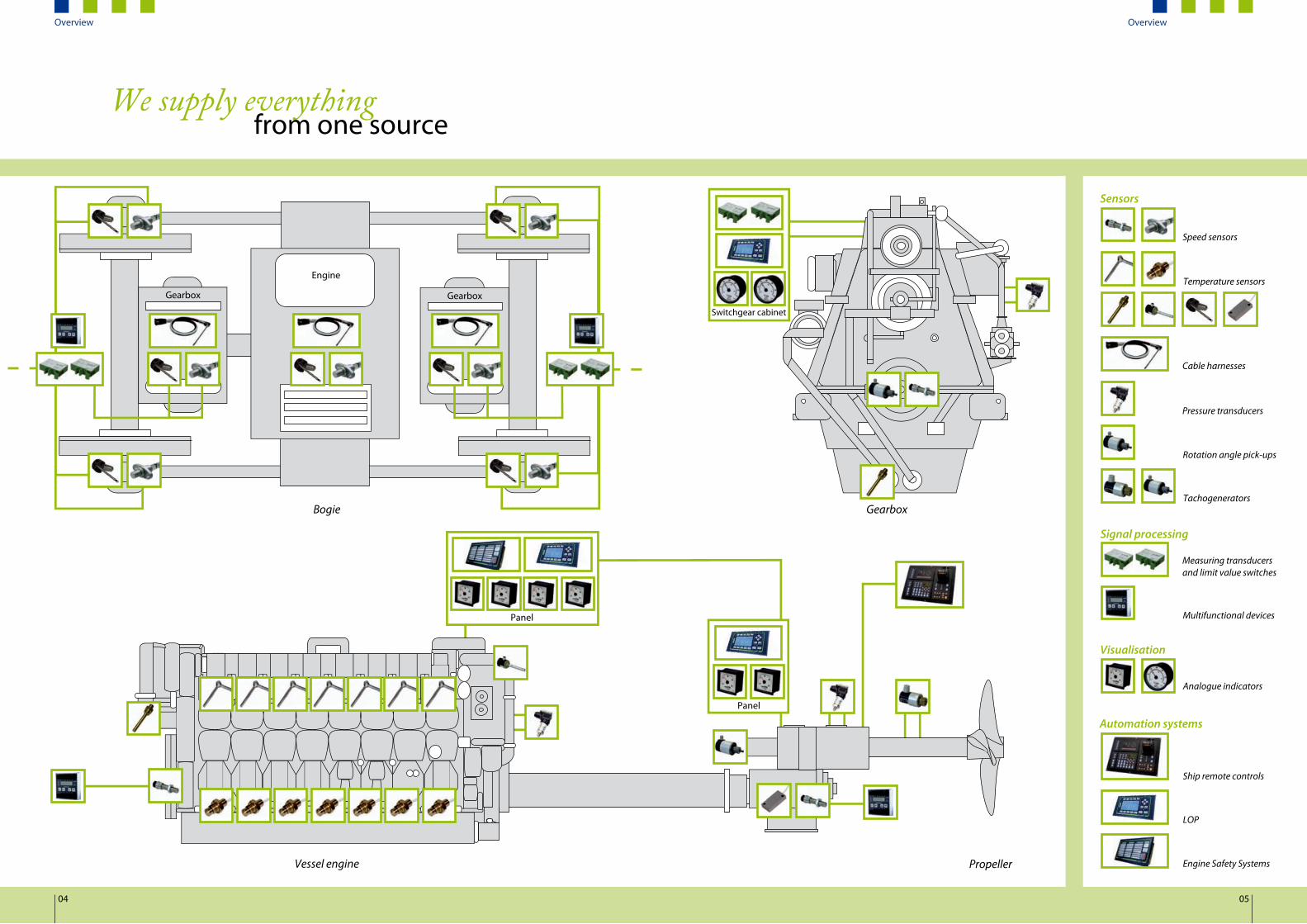
We supply everythingfrom one source
Vessel engine
Bogie Gearbox
Propeller
Engine
Gearbox
Panel
Switchgear cabinet
Gearbox
Panel
Visualisation
Signal processing
Sensors
Automation systems
Speed sensors
Temperature sensors
Rotation angle pick-ups
Tachogenerators
Pressure transducers
Measuring transducers and limit value switches
Multifunctional devices
Cable harnesses
Analogue indicators
Ship remote controls
LOP
Engine Safety Systems
04 05
Overview Overview
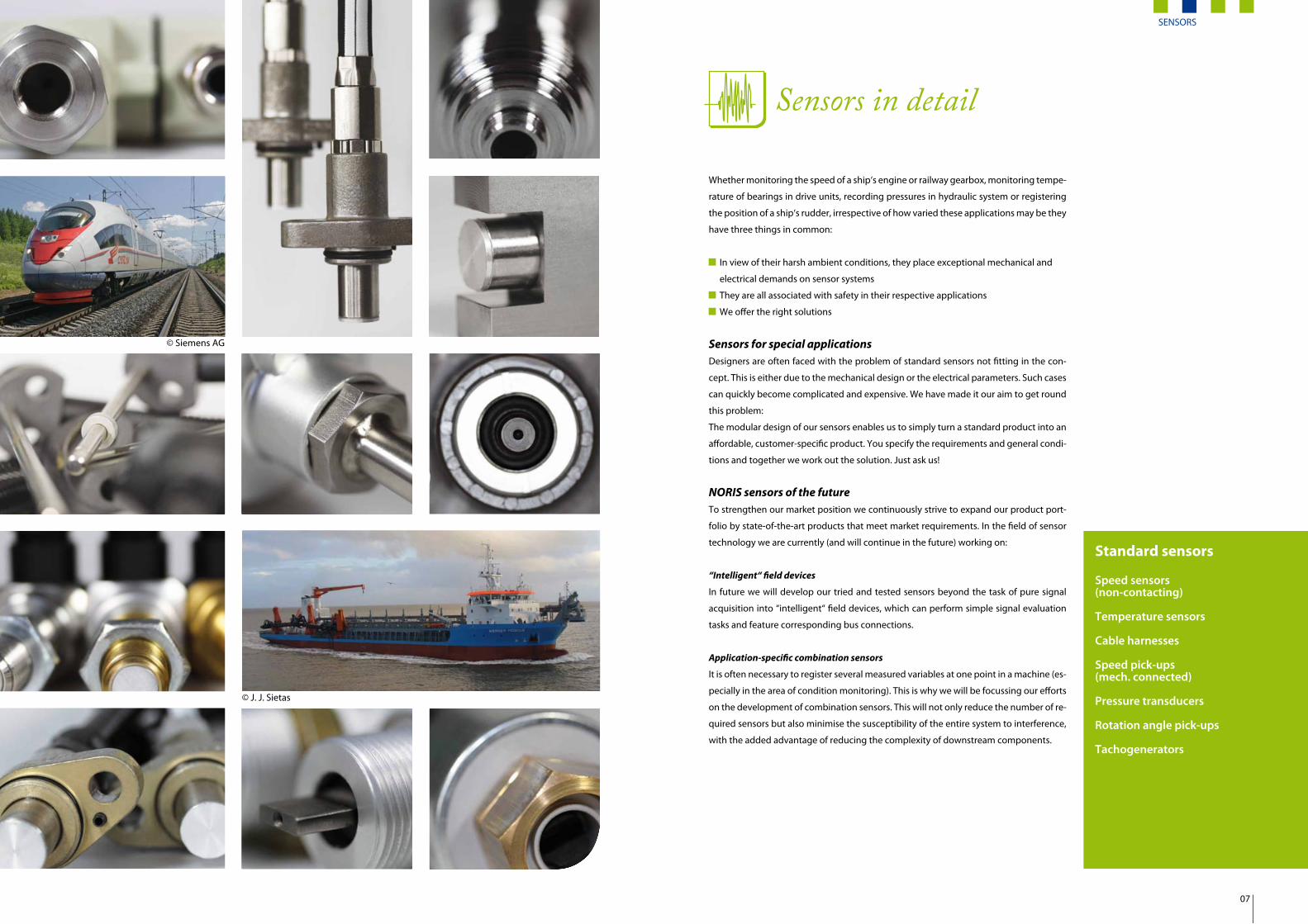
Sensors in detail
Whether monitoring the speed of a ship‘s engine or railway gearbox, monitoring tempe-
rature of bearings in drive units, recording pressures in hydraulic system or registering
the position of a ship‘s rudder, irrespective of how varied these applications may be they
have three things in common:
In view of their harsh ambient conditions, they place exceptional mechanical and
electrical demands on sensor systems
They are all associated with safety in their respective applications
We offer the right solutions
Sensors for special applicationsDesigners are often faced with the problem of standard sensors not fitting in the con-
cept. This is either due to the mechanical design or the electrical parameters. Such cases
can quickly become complicated and expensive. We have made it our aim to get round
this problem:
The modular design of our sensors enables us to simply turn a standard product into an
affordable, customer-specific product. You specify the requirements and general condi-
tions and together we work out the solution. Just ask us!
NORIS sensors of the futureTo strengthen our market position we continuously strive to expand our product port-
folio by state-of-the-art products that meet market requirements. In the field of sensor
technology we are currently (and will continue in the future) working on:
“Intelligent“ field devices
In future we will develop our tried and tested sensors beyond the task of pure signal
acquisition into “intelligent“ field devices, which can perform simple signal evaluation
tasks and feature corresponding bus connections.
Application-specific combination sensors
It is often necessary to register several measured variables at one point in a machine (es-
pecially in the area of condition monitoring). This is why we will be focussing our efforts
on the development of combination sensors. This will not only reduce the number of re-
quired sensors but also minimise the susceptibility of the entire system to interference,
with the added advantage of reducing the complexity of downstream components.
Standard sensors
Speed sensors(non-contacting)
Temperature sensors
Cable harnesses
Speed pick-ups(mech. connected)
Pressure transducers
Rotation angle pick-ups
Tachogenerators
© Siemens AG
© J. J. Sietas
SENSORS
07

Speed sensors
Inductive-magnetic principle; FAJ
Difference-hall effect principle; FAH
Eddy current principle
Signalacquisition
The sensor element consists of a permanent magnet and a coil.Toothed wheels or impulse bandsinduce a voltage in the sensor coil.
The sensor element consists of a permanent magnet and a differential Hall element.Toothed wheels or impulse bands change the Hall voltage.
The sensor element consists of excitation and evaluation coils.Toothed wheels or impulse bandsinduce an eddy current in the evaluation coils.
Frequency 5 ... 10,000 Hz Approx. 0 ... 20,000 Hz 0 ... 10,000 Hz (optionally up to 20,000 Hz)
Module ≥ m2 (restricted m1) ≥ m2 (restricted m1) ≥ m1
Distance Recommended: 1 ... 3 mm (5 mm and more possible)
Recommended: 1 ... 2 mm (max. 3 mm)
Recommended: 0.5 ... 1 mm (max. 1.5 mm)
Installation mode
Direction-insensitive Direction-sensitive Direction-sensitive
Applicationsand specialfeatures
Standard applications• Easy to use • Large error tolerance• Large temperature range
Standard and special applications• Can be used at frequencies below
5 Hz• Differential principle:
- Immune to radial toothed wheel vibration (e.g. bearing play,concentricity error)
- Reduction of interference of external magnetic alternating fields (e.g. electric motor magnetic fields)
Special applications• Can be used at frequencies below
5 Hz• Scanning of aluminium, brass and
stainless steel- Reduced weight
• Immune to ferrous metal dust and chips*)- Use in immediate vicinity of brake
dust- Use in “ferrous“ environments- Low maintenance
Today, non-contacting speed sensors are predominantly used to monitor the speed of machines, engines or motors. These sensors
register the rotation of toothed wheels made from ferromagnetic metals such as iron and steel but also aluminium. Depending on
requirements, various measurement principles (see table) can be used (inductive-magnetic principle, difference-hall-effect princip-
le, eddy current principle). So-called impulse bands can also be fitted to enable non-contacting signal acquisition of smooth shafts.
Furthermore, any movement of metal parts or changes in their geometry can be measured with these sensors.
Special applicationsMultichannel sensors
We equip our speed sensors for different
combinations of electrical output signals.
In addition to optimum adaptation of
sensors to a downstream evaluation unit,
this makes it possible to detect direction
of rotation or provide maximum security
by use of redundant signal outputs.
Phase offset of two signals by 90°
Additional inverted signals
Woodward regulator (UOUT = ±½ x UB)
Two galvanically isolated sensor
systems in one housing
Integrated directional rotation
recognition
Integrated standstill monitoring
Galvanically isolated parallel output
for individual control tasks
High temperature applications
For such applications, we offer sensors
that operate based on the inductive-ma-
gnetic measuring principle. These devices
are available with a signal amplifier for a
maximum operating temperature of up
to 160 °C. The special design of the head
unit with integrated insulation element
thermally decouples the electronics of
the signal amplifier from the sensor tip.
This guarantees a long service life even
under difficult thermal conditions. These
devices are available without a signal am-
plifier for a maximum operating tempera-
ture of up to 220 °C.
*) Due to the fact that this measuring principle involves no permanent magnets, the sensor head will not become clogged with metal chips during operation. This reduces the maintenance intervals.
Functional principleThe rotary speed registered by the sensor
is converted by a signal amplifier into an
electrical squarewave signal with a fre-
quency that is directly proportional to
the speed. The signal can be evaluated or
transformed by a downstream signal pro-
cessing component.
Main featuresOur speed sensors exhibit the following properties:
Mechanics
Sturdy design with threaded rod or flange connection
Different housing materials (e.g. brass, stainless steel or aluminium)
Different connectors, threads and rod lengths
Test prod completely protected by metal enclosed end face, resistant to splash oil
and lubricants even at high temperatures
Protection class of housing - IP66/IP67 (IP68 on request)
Connection lines protected by unique protective tube design - see information on
cable harnesses (page 12)
Electronics
Status shown by status LEDs
Interference-immune output signal
Inputs and outputs protected against polarity reversal and overloading
Matching measuring transducers and limit value switches available or already
integrated
Environmental influences
High EMC protection conforming to branch-specific standards
Large operating temperature range -40 °C ... +125 °C
Test prod temperature up to +175 °C
Outstanding resistance to vibration and shock
08 09
Speed sensors
Temperature sensors
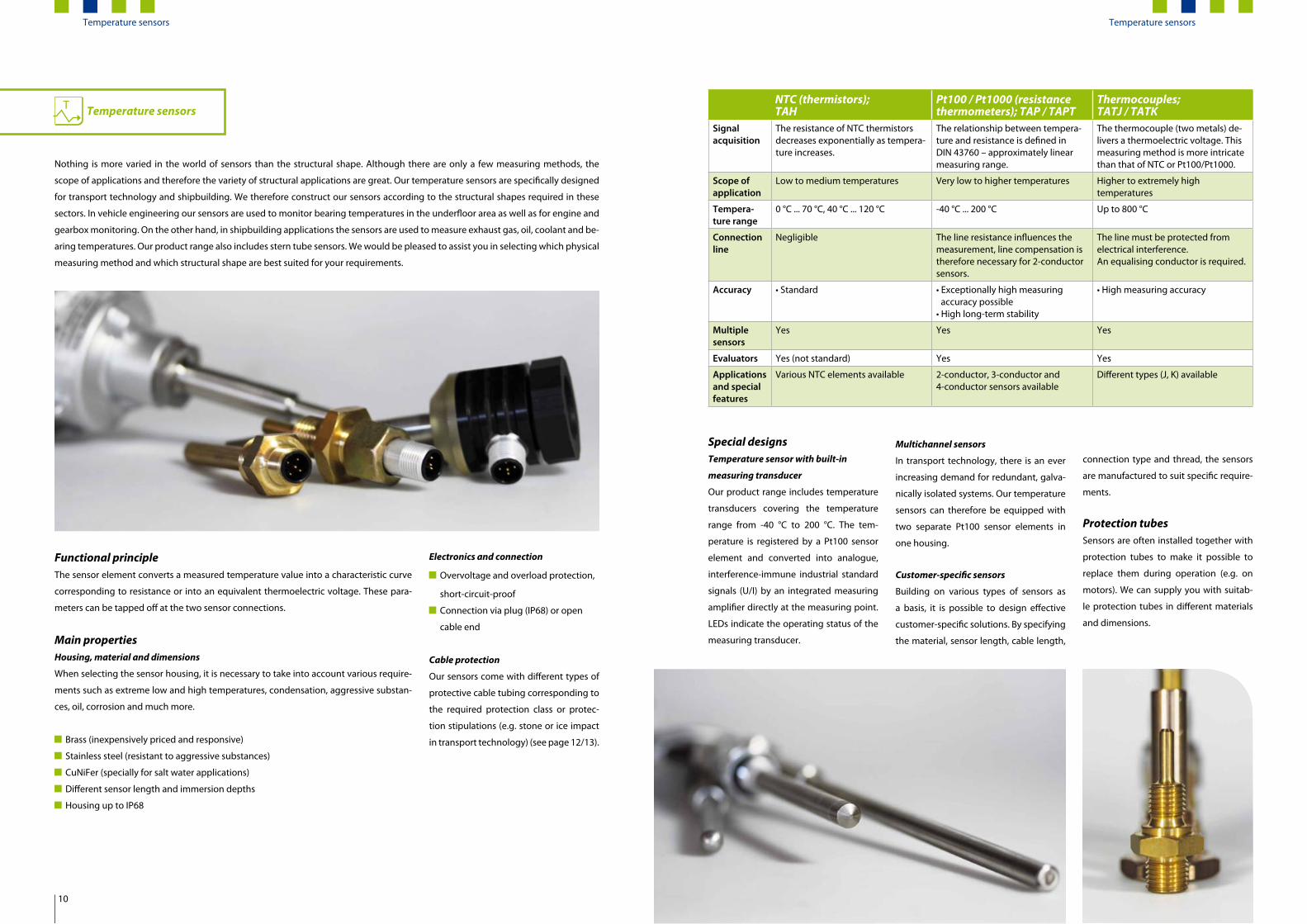
Nothing is more varied in the world of sensors than the structural shape. Although there are only a few measuring methods, the
scope of applications and therefore the variety of structural applications are great. Our temperature sensors are specifically designed
for transport technology and shipbuilding. We therefore construct our sensors according to the structural shapes required in these
sectors. In vehicle engineering our sensors are used to monitor bearing temperatures in the underfloor area as well as for engine and
gearbox monitoring. On the other hand, in shipbuilding applications the sensors are used to measure exhaust gas, oil, coolant and be-
aring temperatures. Our product range also includes stern tube sensors. We would be pleased to assist you in selecting which physical
measuring method and which structural shape are best suited for your requirements.
Special designsTemperature sensor with built-in
measuring transducer
Our product range includes temperature
transducers covering the temperature
range from -40 °C to 200 °C. The tem-
perature is registered by a Pt100 sensor
element and converted into analogue,
interference-immune industrial standard
signals (U/I) by an integrated measuring
amplifier directly at the measuring point.
LEDs indicate the operating status of the
measuring transducer.
T NTC (thermistors);TAH
Pt100 / Pt1000 (resistance thermometers); TAP / TAPT
Thermocouples;TATJ / TATK
Signalacquisition
The resistance of NTC thermistors decreases exponentially as tempera-ture increases.
The relationship between tempera-ture and resistance is defined in DIN 43760 – approximately linear measuring range.
The thermocouple (two metals) de-livers a thermoelectric voltage. This measuring method is more intricate than that of NTC or Pt100/Pt1000.
Scope ofapplication
Low to medium temperatures Very low to higher temperatures Higher to extremely high temperatures
Tempera-ture range
0 °C ... 70 °C, 40 °C ... 120 °C -40 °C ... 200 °C Up to 800 °C
Connectionline
Negligible The line resistance influences the measurement, line compensation is therefore necessary for 2-conductorsensors.
The line must be protected fromelectrical interference. An equalising conductor is required.
Accuracy • Standard • Exceptionally high measuring accuracy possible
• High long-term stability
• High measuring accuracy
Multiplesensors
Yes Yes Yes
Evaluators Yes (not standard) Yes Yes
Applicationsand specialfeatures
Various NTC elements available 2-conductor, 3-conductor and 4-conductor sensors available
Different types (J, K) available
Functional principleThe sensor element converts a measured temperature value into a characteristic curve
corresponding to resistance or into an equivalent thermoelectric voltage. These para-
meters can be tapped off at the two sensor connections.
Main propertiesHousing, material and dimensions
When selecting the sensor housing, it is necessary to take into account various require-
ments such as extreme low and high temperatures, condensation, aggressive substan-
ces, oil, corrosion and much more.
Brass (inexpensively priced and responsive)
Stainless steel (resistant to aggressive substances)
CuNiFer (specially for salt water applications)
Different sensor length and immersion depths
Housing up to IP68
Electronics and connection
Overvoltage and overload protection,
short-circuit-proof
Connection via plug (IP68) or open
cable end
Cable protection
Our sensors come with different types of
protective cable tubing corresponding to
the required protection class or protec-
tion stipulations (e.g. stone or ice impact
in transport technology) (see page 12/13).
Multichannel sensors
In transport technology, there is an ever
increasing demand for redundant, galva-
nically isolated systems. Our temperature
sensors can therefore be equipped with
two separate Pt100 sensor elements in
one housing.
Customer-specific sensors
Building on various types of sensors as
a basis, it is possible to design effective
customer-specific solutions. By specifying
the material, sensor length, cable length,
connection type and thread, the sensors
are manufactured to suit specific require-
ments.
Protection tubesSensors are often installed together with
protection tubes to make it possible to
replace them during operation (e.g. on
motors). We can supply you with suitab-
le protection tubes in different materials
and dimensions.
Temperature sensors
10
Temperature sensors
Cable harnesses
Customer-specific cable harnesses
On request, we are able to assemble customised cable harnesses to suit your specific
requirements. Several sensors (mostly temperature and/or speed sensors), a plug con-
nector of your choice and protective tubing, if necessary, are combined to make a cable
harness, thus creating a rugged sensor assembly. Our technicians take measurements
on site to ensure optimum adaptation of the cable lengths to the gearbox, engine/mo-
tor, etc.
CablingOur sensors are always equipped with the cable types specified for the vehicle enginee-
ring sector. We apply the following principles to cables in cable harnesses with protec-
tive tubing:
Instead of individual conductors cables are used so that, together with the cable
sheathing, a multi-layered protection system is created, thus effectively avoiding
water ingress as the result of damage to the protective tubing and cable chafing
in the tubing.
All sensor terminals are led directly to the connector to avoid electrical connections
in the protective tubing.
SensorsOur cable harnesses are predominantly connected to speed and/or temperature sen-
sors. The sensors can be combined in any configuration. You will find further informa-
tion on speed and temperature sensors in this brochure or we will gladly provide the
information on request.
Other peripheries are possible and a meeting can be arranged to discuss them in detail.
All our sensors have, of course, been developed in accordance with applicable guide-
lines and are equipped with standard installation flanges as required in the transport
technology applications.
Thanks to the reliability and robustness of our products, for years NORIS has been a leading speed and temperature sensor manufac-
turer in the transport technology sector. A key point for us is to guarantee the effectiveness of our products under extreme conditions.
Great demands are placed on sensors and wiring particularly in the underfloor area. While sensors are mostly installed with mechanical
protection, the cables are often exposed to direct impact of stones and ice and therefore represent a weak point.
For this reason, on customer request, we supply our sensors with protective tubing.
Corrugated tubing for standard applicationsAs common practice in the sector, we
use corrugated tubing for standard ve-
hicle engineering applications to provide
adequate mechanical protection in many
applications. Further advantages include
the low weight and high degree of flexibi-
lity for installation.
Special protective tubingunder extreme conditionsOur years of experience and our close
cooperating with our customers have
proven that corrugated tubing cannot
adequately protect cabling from stone
and ice impact especially on high speed
trains, with soiled track beds and under
extreme temperatures.
Example:
In harsh winters, snow and ice collect on
the corrugated tubing thus drastically in-
creasing the weight. The extremely low
temperatures make the material brittle. Me-
chanical stress such as vibration and shock
can easily cause conventional corrugated
tubing to break.
To protect our products from such extre-
me conditions we have developed a spe-
cial solution, placing us one step ahead of
our competitors:
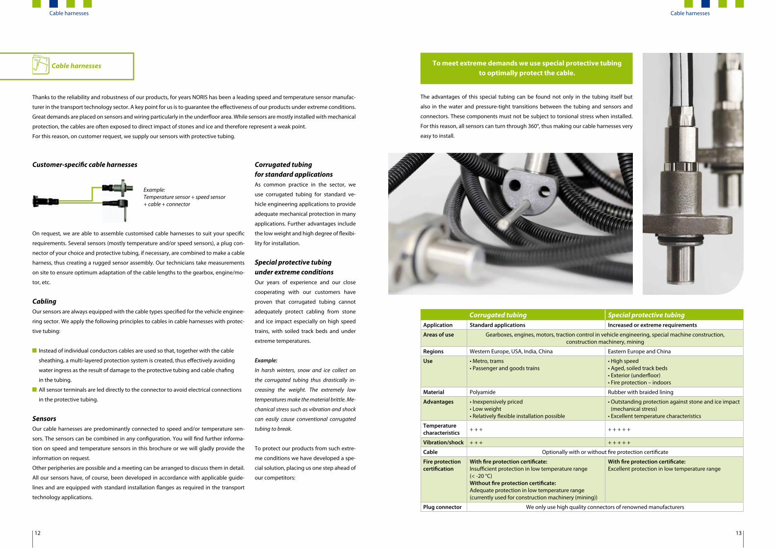
The advantages of this special tubing can be found not only in the tubing itself but
also in the water and pressure-tight transitions between the tubing and sensors and
connectors. These components must not be subject to torsional stress when installed.
For this reason, all sensors can turn through 360°, thus making our cable harnesses very
easy to install.
Corrugated tubing Special protective tubingApplication Standard applications Increased or extreme requirements
Areas of use Gearboxes, engines, motors, traction control in vehicle engineering, special machine construction, construction machinery, mining
Regions Western Europe, USA, India, China Eastern Europe and China
Use • Metro, trams• Passenger and goods trains
• High speed• Aged, soiled track beds • Exterior (underfloor)• Fire protection – indoors
Material Polyamide Rubber with braided lining
Advantages • Inexpensively priced • Low weight• Relatively flexible installation possible
• Outstanding protection against stone and ice impact(mechanical stress)
• Excellent temperature characteristics
Temperaturecharacteristics + + + + + + + +
Vibration/shock + + + + + + + +
Cable Optionally with or without fire protection certificate
Fire protectioncertification
With fire protection certificate:Insufficient protection in low temperature range (< -20 °C)Without fire protection certificate:Adequate protection in low temperature range (currently used for construction machinery (mining))
With fire protection certificate:Excellent protection in low temperature range
Plug connector We only use high quality connectors of renowned manufacturers
To meet extreme demands we use special protective tubing to optimally protect the cable.
Example:Temperature sensor + speed sensor+ cable + connector
Cable harnesses
12 13
Cable harnesses

Speed pick-ups
Speed pick-ups are used to convert rotary motion into electrically proportional square-wave signals where the drive shaft of the speed
pick-up is mechanically connected directly to the speed source (e.g. motor, generator). Alternatively, a coupling or a flexible shaft can
be used as the connection.
Functional principleThe rotation information of the drive
shaft is converted by a Hall switch in the
Single-phase; NAD1, NAD2 Two-phase with direction of rotation relay; NADS3Application Speed acquisition on engines, machinery and gearboxes
Housing and mounting
• Metal housing – IP67• Shaft: Slot mounting (NAD1)• Shaft: Blade mounting (NAD2)• Mounting: Screw-in thread M22 x 1.5
• Metal housing – IP66 (plastic terminal box)• Shaft: (Ø 10 mm) for coupling• Mounting: Spigot – Ø 40 x 40 mm
Frequency 0 ... 6000 rpm (0 Hz ... 1500 Hz) 0 ... 6000 rpm (0 Hz ... 6000 Hz)
Connection Euro M12 x 1 Screw terminals (1.5 mm²)
Temperaturerange -25 °C ... 100 °C -25 °C ... 85 °C
Special features • Compact design for directly screwing into engine block
• Two square-wave signals for detecting direction of rotation• Binary direction of rotation signal (relay)
• Comprehensive range of accessories, as well as matching measuring transducers and limit value switches available• Modular design for special solutions on request
Pressure transducersP
Pressure transducers register pressures of liquid and gaseous media and convert the
acquired information into linear, proportional, electrical industry standard signals at the
output. The devices are characterised by high degree of reliability, sturdy and compact
design as well as flexibility in adapting to different measurement tasks.
Their applications include the monitoring of:
Lubricating oil and fuel pumps on combustion engines
Hydraulic and pneumatic systems
Filters, compressors, pressure tanks
Fill levels in tank systems
Our pressure transducers are available both as screw-in devices as well as surface-moun-
ted devices with holes for individual piping and are suitable for measuring absolute and
relative pressures (as from -1 bar).
PAG8, PAA8 VD6Application Registering pressure of liquid and gaseous medium
Housing and mounting
• Cylindrical metal housing*) – IP65/IP67• For directly screwing into a pressure tank for example• Thread types: G¼, ¼-18 NPT, M14 x 1.5
• Cuboid aluminium housing*) – IP65• For rigid and flexible piping• Thread types: G¼ female, G½ male
Pressure ranges Up to 600 bar (relative, absolute); special pressure ranges possible on request
Electricalconnection
• Right-angle connector DIN 175301• Euro plug M12 x 1, cable outlet
• Screw terminals (1.5 mm²)
Output signals • 4 ... 20 mA (2-conductor)• 0 ... 10 V (3-conductor)
• 4 ... 20 mA (2-conductor)
Temperaturerange Measured medium temperature -30 °C ... +100 °C
Special features Reducers and damping elements available
*) Parts and housings that come in contact with the measured medium are made from CrNi steel
Functional principlePiezo-resistive sensor elements are used
for measuring ranges up to 10 bar while
thin-film sensors are used for measuring
ranges as from 16 bar. A downstream
amplifier stage converts the sensor sig-
nals into an analogue industry standard
signal.
To increase the service life of old machi-
nes they are often equipped with modern
control components as part of RETROFIT
solutions. In connection with new control
systems, outdated sensors in particular
Outstanding accuracy and highly
stable output signal (square-wave
signal) adapted to modern control
systems
Lower procurement costs, decreased
susceptibility to faults and longer
maintenance intervals by reducing the
number of mechanical components
Directional rotation detection
without additional expenditure
Procurement of spare parts is more
reliable, uncomplicated and less costly
device into a squarewave signal that is
proportional to the speed. An integrated
signal amplifier makes it available at the
output.
often pose problems in terms of reliabi-
lity, accuracy, signal compatibility as well
as signal stability and consequently also
need to be replaced. For speed acquisiti-
on, a combination of a flexible shaft and
tachogenerator was often used in older
systems. Our NAD1 and NAD2 speed pick-
ups have been specially developed as a
substitute for this component assembly
and offers the following advantages:
“Substitute for flexible shaft“ - RETROFIT
Speed pick-ups
14
Pressure transducers

Rotation angle pick-ups
Functional principleIn the device, the rotation of the drive
shaft is transferred to a precision poten-
tiometer featuring conductive plastics
technology, which enables virtually infi-
nite resolution over a service life of more
than 10 million shaft rotations. The drive
shaft turning through the specified angle
range initiates an analogue change in the
resistance by the specified ohmic value.
These potentiometers are designed as
2-stage or 3-stage units to enable signal
evaluation in redundant or galvanically
isolated systems. The connections of each
potentiometer stage are led outwards for
external wiring.
Our rotation angle pick-ups are used wherever angular positions need to be registered reliably and converted into electrical signals
by control systems for status monitoring purposes. The sensors are used, for example, in systems for displaying actual values and limit
thresholds. As angle of rotation sensors are mostly installed directly on the bearing-mounted shafts of the objects to be measured and
are therefore often difficult to access in such system, we attach particular importance to ensuring our sensors are durable, provide a
long service life and are maintenance-free.
Series 1; DWA...-1 Series 2; DWA...-2 Series 3; DWA...-3Application Registering propeller pitch and rudder position in shipbuilding applications
Housing and mounting
• Metal housing – IP66• Spigot – Ø 40 x 40 mm• Similar to DIN 5377, connection 2
• Metal housing – IP66• Spigot – Ø 30 x 30 mm• Similar to DIN 5377, connection 1
• Metal housing – IP66• Spigot – Ø 40 x 40 mm• Similar to DIN 5377, connection 2
Angle ofrotation
Standard: 50°, 70°, 90°, 180°, 240°, 320° Standard: 90°
Other ranges on request; 360° rotation possible – no mechanical stop
Potentio-meter and channels
Dual – galvanically isolated Dual – galvanically isolated Triple – galvanically isolated
Resistance – standard: 2 kΩ 1 kΩ
Connection Terminals Cables (7 x 0.5 mm²) Cables (10 x 0.5 mm²)
Tempera-ture range -40 °C ... +70 °C
Specialfeatures
• MED (Marine Equipment Directive) certified for rudder blade position display: The complete measurement chain was certified together with our indicators in the NORIMETER product family
• Comprehensive range of accessories such as flanges and retaining fixtures as well as matching measuring transducers and limit value switches available
• Modular design for special solutions on request
Tachogenerators
Our AC tachogenerators are predomi-
nantly used wherever operation of indi-
cator and display devices independent
of mains power supply is required. These
maintenance-free devices are built to be
extremely robust, making them ideal for
harsh operating conditions. They can be
driven either with couplings directly at
the rotor shaft or indirectly via friction
wheels, belt pulleys, sprockets or flexible
shafts.
Functional principleTachogenerators operate in accordance
with the generator or exciter principle si-
milar to a bicycle dynamo: A permanent
magnet rotates in a fixed winding where
it induces an AC voltage signal that is pro-
portional to the speed of the drive shaft.
This voltage and/or its frequency can be
used as measuring variables.
Multiphase AC voltage tachogenerators
Multiphase AC tachogenerators supply
two identical, galvanically isolated sinu-
soidal signals that are electrically offset by
90° with respect to each other. This makes
it possible for a downstream evaluation
unit to determine direction of rotation.
Tachogenerators with integrated
direction of rotation switch
Our devices are available with integrated
directional rotation recognition. Depen-
ding on the type of device, direction of
rotation information can be optionally
output as:
Polarity change of the DC voltage
signal
Floating changeover contact
Tachogenerators; GE / GZApplication Registering speed without auxiliary voltage
Housing • Metal housing – IP65/IP66• Drive side IP54
Mechanicalconnection
• The connection dimensions (pin/shaft) correspond toDIN specifications
• Variable mechanical connections possible
Speed range Up to max. 6000 rpm (depending on type)
Electricalconnection
Tab connector, connection cable, screw terminals in terminal box
Output signals • AC and/or DC voltage output• Various voltage characteristics available
Temperature range -20 °C ... +80 °C
Special features • Directional rotation recognition possible• Mounting elements such as flanges and holders available • Drive elements such as couplings, belt pulleys or friction
wheels available• Powerful for supplying several indicators/evaluators
Irrespective of the speed, a change in
direction of rotation is detected as from
approx. ¼ turn of the drive shaft. The AC
voltage signal can be additionally used
for the purpose of evaluating frequency.
Rotation angle pick-ups
16 17
Tachogenerators
Signal processing in detail
In the field of signal processing, our product portfolio ranges from simple control units
such as measuring transducers, limit value switches, isolation amplifiers through multi-
functional devices to highly complex automation systems (refer to our product brochu-
res on automation components).
Control units for special applicationsOur customers‘ demanding tasks and varied applications often require individual
solutions. We specialise specifically in satisfying these requirements and offer you the
following advantages:
Your new device optimally matched to your specific application
You only get and pay for the functions you really need
Interface compatibility with other components possible without the need for
additional devices
Standard devices
Measuring transducers
Limit value switches
Multifunctional devices
Automation systems(see product brochure on automation components)
Our standard devices come with built-in functions that already cover most applications. By the use of innovative technologies and
sophisticated concepts we are able to offer you inexpensively priced, high quality products also for your specific objectives. All our
devices can be easily adapted to changing conditions or special requirements.
Design according to your requirements:
Combine functions and interfaces in analogue and digital technology
Determine input and output signals and their accuracy
Select housings, mechanical systems, connectors and materials for your device
Determine the relevant standards and necessary approvals
Our control units of the futureWe are constantly improving our sophisticated and well-proven products and concepts. For us, to keep pace with technological deve-
lopment means to recognise today the trends of tomorrow. You, as our customer, are most important because your requirements will
become the standards of tomorrow. These are your benefits:
We integrate successful, individual solutions
Cooperating with our customers sheds light on new approaches that we then integrate in our standard products to fine-tune them for
their intended application. One efficient product instead of many individual devices – that is our goal.
We incorporate technical innovation in existing products
The use of state-of-the-art electronic components allows us to achieve greater accuracy, improve performance and even develop
new additional functions. For this reason we are continually developing our products in line with technological developments while
keeping prices virtually constant.
SIGNAL PROCESSING
19
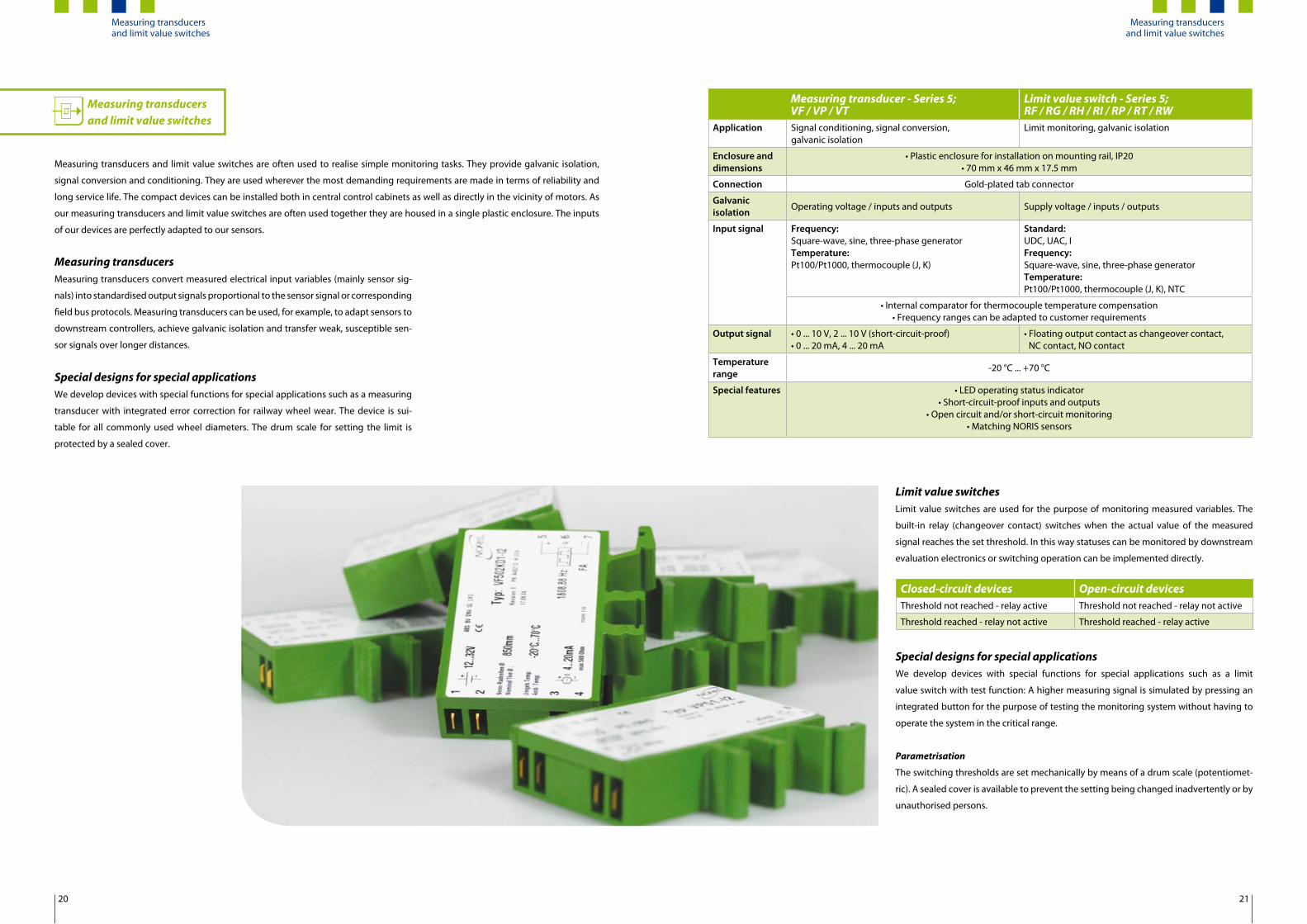
Measuring transducers and limit value switches
Measuring transducers and limit value switches are often used to realise simple monitoring tasks. They provide galvanic isolation,
signal conversion and conditioning. They are used wherever the most demanding requirements are made in terms of reliability and
long service life. The compact devices can be installed both in central control cabinets as well as directly in the vicinity of motors. As
our measuring transducers and limit value switches are often used together they are housed in a single plastic enclosure. The inputs
of our devices are perfectly adapted to our sensors.
Measuring transducersMeasuring transducers convert measured electrical input variables (mainly sensor sig-
nals) into standardised output signals proportional to the sensor signal or corresponding
field bus protocols. Measuring transducers can be used, for example, to adapt sensors to
downstream controllers, achieve galvanic isolation and transfer weak, susceptible sen-
sor signals over longer distances.
Special designs for special applicationsWe develop devices with special functions for special applications such as a measuring
transducer with integrated error correction for railway wheel wear. The device is sui-
table for all commonly used wheel diameters. The drum scale for setting the limit is
protected by a sealed cover.
Limit value switchesLimit value switches are used for the purpose of monitoring measured variables. The
built-in relay (changeover contact) switches when the actual value of the measured
signal reaches the set threshold. In this way statuses can be monitored by downstream
evaluation electronics or switching operation can be implemented directly.
Special designs for special applicationsWe develop devices with special functions for special applications such as a limit
value switch with test function: A higher measuring signal is simulated by pressing an
integrated button for the purpose of testing the monitoring system without having to
operate the system in the critical range.
Parametrisation
The switching thresholds are set mechanically by means of a drum scale (potentiomet-
ric). A sealed cover is available to prevent the setting being changed inadvertently or by
unauthorised persons.
Measuring transducer - Series 5; VF / VP / VT
Limit value switch - Series 5;RF / RG / RH / RI / RP / RT / RW
Application Signal conditioning, signal conversion,galvanic isolation
Limit monitoring, galvanic isolation
Enclosure anddimensions
• Plastic enclosure for installation on mounting rail, IP20 • 70 mm x 46 mm x 17.5 mm
Connection Gold-plated tab connector
Galvanic isolation
Operating voltage / inputs and outputs Supply voltage / inputs / outputs
Input signal Frequency: Square-wave, sine, three-phase generatorTemperature: Pt100/Pt1000, thermocouple (J, K)
Standard: UDC, UAC, IFrequency: Square-wave, sine, three-phase generator Temperature:Pt100/Pt1000, thermocouple (J, K), NTC
• Internal comparator for thermocouple temperature compensation • Frequency ranges can be adapted to customer requirements
Output signal • 0 ... 10 V, 2 ... 10 V (short-circuit-proof)• 0 ... 20 mA, 4 ... 20 mA
• Floating output contact as changeover contact, NC contact, NO contact
Temperaturerange -20 °C ... +70 °C
Special features • LED operating status indicator • Short-circuit-proof inputs and outputs
• Open circuit and/or short-circuit monitoring • Matching NORIS sensors
Closed-circuit devices Open-circuit devicesThreshold not reached - relay active Threshold not reached - relay not active
Threshold reached - relay not active Threshold reached - relay active
Measuring transducers and limit value switches
20 21
Measuring transducers and limit value switches

Multifunctional devices
Our multifunctional devices are a combination of measuring transducers and switch-
gear. They are used wherever several variables are to be monitored with one device,
special measurements such as slip and offset measurement are performed and flexible
parametrisation is required.
Solution-orientated multifunctional devicesOur multifunctional devices are based on solution-orientated design. Recurring appli-
cations that to date had to be realised by several individual components are now per-
formed by one single device. To this end we equip such devices with functions that you
require for your specific applications.
The benefits for you are:
Optimum price/performance ratio by adapting the scope of electronics, interfaces
and functions to specific application requirements
Error minimisation in installation and servicing
Menu-controlled parametrisation for maximum ease of operation
NORISPEED; FMN6Application Evaluation of up to two speed sensors
Housing Sturdy aluminium housing for installation on mounting rail
Connection Connector with spring-loaded contacts
Inputs/signals • Two galvanically isolated frequency inputs (1...12,000 Hz)• Square-wave signal (NORIS standard signal, PNP, NPN)
Outputs/signals • Two galvanically isolated standard signal outputs, parametrisable as 0 ... 5 V, 0 ... 10 V, 2 ... 10 V, +/-5 V, +/-10 V, 0 ... 20 mA and 4 ... 20 mA outputs
• Six relay outputs with working contacts (max. 2 A)• All outputs are short-circuit and overvoltage-proof
Display/LED • Measured value display and menu prompting on integrateddisplay
• LED operating status indicators
Temperature range -20 °C ... +70 °C
Special features Wire break detection (speed sensors)
Speed evaluation with “NORISPEED“NORISPEED is an evaluation unit for con-
nection of up to two speed sensors. The
properties of a measuring transducer and
of a limit value switch are combined and
evaluations based on the acquired mea-
sured data are made available via swit-
ched outputs or standard signal outputs.
The user can set up the device directly
with the aid of menu-controlled navigati-
on and an integrated LC display. Current
measured values can be shown on the
display, making them easy to check.
Applications Speed measurement and conversion
to standard signals
Directional rotation recognition in
reversing gearbox systems
Speed monitoring or engine protec-
tion (nominal speed and overspeed
detection or drive shutdown with
signalling to a remote station,
e.g. to a safety system)
Gearbox monitoring by means of slip
measurement
Application examplesSpeed measurement
Two independent speeds (up to 10,000
rpm) can be registered and converted
into proportional analogue signals. The
digital outputs can be individually desi-
gnated to the two frequency inputs and
assigned different functions (e.g. limit
monitoring).
Directional rotation recognition
The signals of two radially offset speed
sensors or those of a dual sensor are
evaluated in the device and sent to two
digital outputs. All analogue and digital
outputs are freely programmable in this
mode.
Slip measurement
Two speeds are measured and evaluated
with mechanical, parametrisable refe-
rence to each other. The freely program-
mable outputs can forward the speed
signals to a downstream evaluation unit.
The digital outputs can be used for status
messages and limit monitoring purposes.
Offset measurement
Offset measurement refers the measured
speed to a set target speed and the result
is output as an analogue value (via ana-
logue outputs), e.g. to precisely monitor
the target speed of a generator. The sca-
ling of the speed deviation is freely pro-
grammable. The digital outputs can be
used for status messages and limit moni-
toring purposes.
Measured value conversion
The frequency signal can be converted
into standard signals (see table). In con-
nection with directional rotation reco-
gnition, the signal range can be split for
anticlockwise and clockwise rotation.
Multifunctional devices
22 23
Multifunctional devices
Visualisation in detail
Standard indicators
Indicators withmoving-coil
Indicators withstepping-motor drive
Stepping-motor indicator(360° indicator)
Display solutionsas part of automation and safety engineering
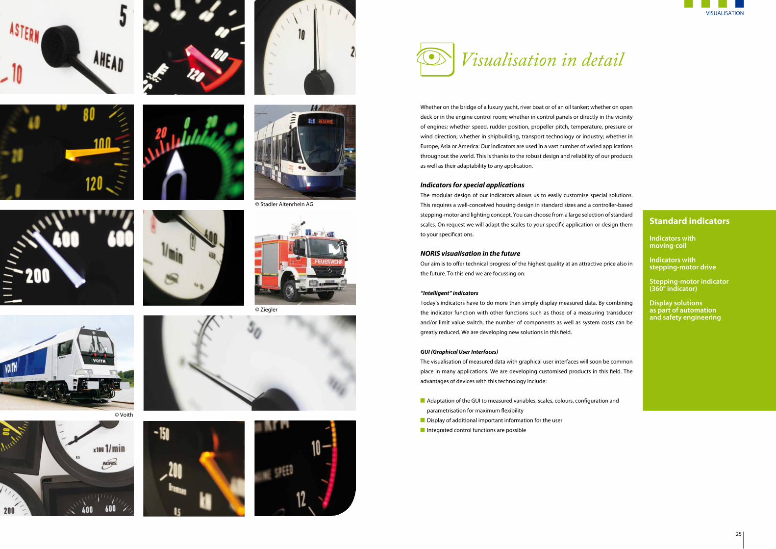
Whether on the bridge of a luxury yacht, river boat or of an oil tanker; whether on open
deck or in the engine control room; whether in control panels or directly in the vicinity
of engines; whether speed, rudder position, propeller pitch, temperature, pressure or
wind direction; whether in shipbuilding, transport technology or industry; whether in
Europe, Asia or America: Our indicators are used in a vast number of varied applications
throughout the world. This is thanks to the robust design and reliability of our products
as well as their adaptability to any application.
Indicators for special applicationsThe modular design of our indicators allows us to easily customise special solutions.
This requires a well-conceived housing design in standard sizes and a controller-based
stepping-motor and lighting concept. You can choose from a large selection of standard
scales. On request we will adapt the scales to your specific application or design them
to your specifications.
NORIS visualisation in the future
Our aim is to offer technical progress of the highest quality at an attractive price also in
the future. To this end we are focussing on:
“Intelligent“ indicators
Today‘s indicators have to do more than simply display measured data. By combining
the indicator function with other functions such as those of a measuring transducer
and/or limit value switch, the number of components as well as system costs can be
greatly reduced. We are developing new solutions in this field.
GUI (Graphical User Interfaces)
The visualisation of measured data with graphical user interfaces will soon be common
place in many applications. We are developing customised products in this field. The
advantages of devices with this technology include:
Adaptation of the GUI to measured variables, scales, colours, configuration and
parametrisation for maximum flexibility
Display of additional important information for the user
Integrated control functions are possible
© Voith
© Stadler Altenrhein AG
© Ziegler
VISUALISATION
25

Analogue indicators
Our analogue indicators feature step-
ping-motor technology or are equipped
with a moving-coil element. They are pri-
marily used wherever great demands are
placed on durability and reliability. They
are largely unaffected by harsh ambient
conditions and thermal extremes.
Long lifetime and easy readable values
even in case of direct sunlight are further
advantages compared to indicators with
displays.
Functional principle and design of the stepping-motor indicator - NORIMETER Our analogue indicators with integrated stepper motor technology are reliable over a long service life. Measured values are digitised
by an A/D converter and shown by means of a processor-controlled, high resolution stepper motor with illuminated plastic pointer on
an individually configurable scale. The combination of high quality components and materials with a sophisticated software system
ensures maximum accuracy and flexibility. The high EMC protection class as well as the immunity to shock and vibration as stipulated
by transport technology and most ship classification bodies enable continuous operation under increased mechanical stress condi-
tions such as direct installation on a motor/engine.
Indicator with moving-coil element; R / RQ Indicator with stepper motor drive; NIR/NIQApplication Low cost; no auxiliary voltage required Universal
Size *) Round: 60, 80, 100, 130, 160; square: 72, 96, 144
Housing Glass-fibre reinforced plastic or metal housing
Protection class Depending on housing – front: up to IP66/IP67; connection side: IP30
Accuracy class 0,5; 1.0; 1.5 depending on measuring system < 0.5
Indicator angle 0° ... 240° 0° ... 300° (pointer); 0° ... 360° (dial)
Illumination Lamps, dimmable LED Dimmable LED; illuminated pointer
Inputs U, I, frequency, resistive inputs U, I, frequency, resistive inputs (galvanically isolated)
Electricalconnection Terminals / various connectors 8-pin or 9-pin Phoenix connector
Temperaturerange -25 °C ... +70 °C
Application andspecial features
• Generally more cost-effective than stepping-motor indicators
• A supply voltage is not absolutely necessary• Exceptional electrical robustness thanks to minimal
circuitry• No electromagnetic radiation
• Precision measured value approach and hold• Outstanding mechanical robustness: Not influenced
by bearing friction and transverse acceleration fromhigh stepper motor actuating forces
• Line compensation possible• Auxiliary energy and sensor failure monitoring
function (live zero)• Automatic zero calibration after switch-on• Scale spread, selectable anticlockwise rotation and
zero point position• Independent pointer position feedback• Operation in any position
*) The dimensions of the housings and control panel apertures conform to applicable standards.
Analogue indicatorsIlluminated scale: white (standard)
Scale labelling: blackPointer: black, unlit
Illuminated scale: black
Scale labelling: colour specified by customerIlluminated pointer: white, red when lit (standard); optionally illuminated yellow or red
Extras Customer logo, different colours, spread, scales for indicatorsturning anticlockwise, double scales on multiple indicators
Main properties of stepping- motor indicators - NORIMETERFunctionalities
MIN-MAX value reading, extreme
value monitoring
Optional binary input and/or switched
output (limit value switches)
Integrated status LED
(e.g. for exceeding limits)
Lighting
Innovative LED lighting concept for
bright, uniform scale and optional
pointer lighting
The basic brightness setting (pointer
and scale separate) can be adapted to
adjacent devices and ambient condi-
tions
360° indicatorsOur 360° indicators that are used in con-
nection with azipods are equipped with
dials instead of pointers. The indicator or
dial performs automatic travel optimisa-
tion.
MED (Marine Equipment Directive)An MED certificate (European Marine
Equipment Directive) is generally requi-
red for use of indicators for ship naviga-
tion (propeller pitch, speed, rudder po-
sition). For this reason, our NORIMETER
stepping-motor indicators have been ap-
proved together with our DWA series ro-
tation angle pick-ups and measuring am-
plifiers as a complete measuring chain in
order to comply will all necessary criteria.
“Intelligent“ indicatorsIn addition to simply showing measured
values, for us the term “intelligent“ indica-
tor means providing extended functions,
which enable the indicator to convert
measured values or evaluate signals. The-
se devices were developed as a solution
to specific problems, thus avoiding unne-
cessary costs.
NORIMETER 3 - Indicator with integrated
directional rotation detection
Two speed sensors or a dual sensor (two
sensors in one enclosure) can be con-
nected to this device without the need
for additional electronics. The indicator
identifies the direction of rotation based
on the phase angle of both sensor signals
and shows it together with the speed on
the scale (right/left stop).
Special solutions
Our indicators can of course be adapted
to specific customer requirements.
You have the choice to:
Select the colour of the scale dial from
a range of colours
Define the colour of the scale
Select the colour of the scale and
pointer lighting
Have customised scale and zero point
calibration
More extensive changes are also possible.
At various points we have already prepa-
red appropriate concepts in advance and
hope we have sparked an interest.
Indicator with integrated display
96 step LED indicators in different
colours (can also be combined with
stepping-motor indicator)
Two-pointer devices
Input and output expansions
Scales and pointersThe “face“ of any indicator is its scale. This
feature gives every indicator its individual
character and personal touch. We have
available a large selection of standard
scales or if necessary we can also create
special scales that precisely conform to
your specific requirements - simply talk
to us.
If not otherwise specified, the scale la-
belling and graduation will conform to
DIN 43802 and DIN 43780.
Analogue indicators
26 27
Analogue indicators

NORIS Automation GmbHMuggenhofer Str. 9590429 NurembergGermany
Phone: +49 911 3201-0Fax: +49 911 [email protected]
Nuremberg Rostock Rotterdam Singapore Shanghai
BR-NAN-Overview en V01.00 - 08/2012 - Errors and modifications excepted.