out-of-plane instability of a rectangular wall …
TRANSCRIPT

OUT-OF-PLANE INSTABILITY OF A RECTANGULAR WALL SPECIMEN SUBJECT TO IN-PLANE CYCLIC LOADING
FARHAD DASHTI1, RAJESH P DHAKAL2, STEFANO PAMPANIN2
1 PhD Candidate, Dept. of Civil and Natural Resources Engineering, Univ. of Canterbury, Christchurch 8140, New Zealand
2 Professor, Dept. of Civil and Natural Resources Engineering, Univ. of Canterbury, Christchurch 8140, New Zealand
ABSTRACT
Out-of-plane instability is identified as one of the failure modes of rectangular reinforced concrete (RC) walls. This mode of failure was previously observed in experimental studies of rectangular walls, and has attracted more attention following the observed damage of several walls in the recent earthquakes in Chile and Christchurch. In this study, the sequence of events that were observed during a rectangular wall experiment in which out-of-plane instability was the main and only failure pattern (i.e. the wall response was not influenced by other failure modes such as bar buckling) is discussed. The postulations and observations presented in some prior research on development of out-of-plane instability of concrete columns representing the boundary zones of rectangular walls are linked with the observations made in this experimental research. The half-scale specimen tested herein represents the first story of a four story prototype wall designed according to NZS3101:2006. Keywords: Structural wall, Out-of-plane deformation, Experimental study INTRODUCTION According to the building performance observed in the recent earthquakes in Chile and New Zealand, lateral instability of structural walls (i.e. out-of-plane buckling) was one of the failure patterns that raised concerns about performance of RC shear wall buildings designed using modern codes (Sritharan et al. 2014). Prior to the Chile earthquake, this failure mechanism had primarily been observed in laboratory tests (Oesterle 1976, Goodsir 1985, Johnson 2010). Out-of-plane buckling (also referred to as out-of-plane instability) refers to the (local) buckling of a portion of a wall section out-of-plane due to in-plane cyclic loading as a result of reversed cyclic inelastic flexural response during an earthquake. The out-of-plane buckling is typically limited to an end region of the wall where vertical tension and compression strains from in-plane cyclic flexure are the greatest (Telleen et al. 2012a). Paulay and Priestley (1993) made recommendations for the prediction of the onset of out-of-plane instability based on the observed response in tests of rectangular structural walls and theoretical considerations of fundamental structural behaviour. Because of very limited available experimental evidences, engineering judgement was relied on extensively. It was concluded that the likelihood of inelastic buckling is more affected by wall length than by unsupported height and the major source of the instability was postulated to be the previously experienced tensile strain than the maximum compression strain.

In order to address this mode of failure, researchers have usually tested columns representing boundary zones of rectangular walls. Chai and Elayer (1999) studied the out-of-plane instability of ductile RC walls by idealizing the end-region of the wall as an axially loaded RC column, as shown in Figure 1, and conducted an experimental study to examine the out-of-plane instability of several RC columns that were designed to represent the end-regions of a ductile planar RC wall under large amplitude reversed cyclic tension and compression.
(a)
(b)
Figure 1 Idealization of reinforced concrete wall in end regions: (a) opening of cracks under tension cycle; and (b) closing of cracks under compression cycle (Chai and
Elayer 1999) Based on this study, the critical influence of the maximum tensile strain on the lateral instability of slender rectangular walls was confirmed and the basic behaviour of the wall end-regions under an axial tension and compression cycle was described by axial strain versus out-of-plane displacement and axial strain versus axial force plots shown in Figure 2. Also, based on a kinematic relation between the axial strain and the out-of-plane displacement, and the axial force versus the axial strain response, a model was developed for the prediction of the maximum tensile strain. Points a-f display different stages of the idealized column response and are briefly described in Table 1. .
(a)
(b)
Figure 2. Axial reversed cyclic response of reinforced concrete column: (a) nominal axial strain versus out-of-plane displacement; and (b) nominal axial strain versus axial
force (Chai and Elayer 1999).

Table 1. Behavior of wall end-region under the loading cycle shown in Figure 2 Path
Loading o-a Large tensile strain
Unloading a-b Elastic strain recovery mainly in reinforcing steel
Reloading
b-c Reloading in compression on the cracked concrete column accompanied by an out-of-plane displacement; yielding of the reinforcement closer to the applied axial force resulting in a reduced transverse stiffness of the column and an increased out-of-plane displacement.
c-d Compression yielding in the second layer of the reinforcement, and a rapid increase in the out-of-plane displacement
d-e Closure of cracks at Point d and decrease of out-of-plane displacement and increase of out-of-plane displacement after significant compressive strain is developed in the compressed concrete
d-f An excessive crack opening where subsequent compression would not result in the closure of the cracks but a continued increase in the out-of-plane displacement and eventual buckling of the column
As can be seen in Figure 2 and Table 1, the idealized column was assumed to consist of the loading stage where a large tensile strain was applied to the specimen (Path o-a), the unloading branch (Path a-b) corresponding to elastic strain recovery mainly in reinforcement steel and the reloading in compression which can be either Path b-c-d-e or Path b-c-d-f. During Path b-c, when the axial compression is small, the compressive force in the column is resisted entirely by the reinforcement alone as the cracks are not closed, and a small out-of-plane displacement would occur due to inherent eccentricity of the axial force. The increase in axial compression would lead to yielding of the reinforcement in one side of the wall section; thereby resulting in a reduced transverse stiffness of the column and an increased out-of-plane displacement. Path c-d corresponds to compression yielding in the second layer of the reinforcement due to further increase in the axial compression which could rapidly increase the out-of-plane displacement. Response of the idealized column after Point d depends on the initial tensile strain. If the initial tensile strain is not excessive, the cracks could close at Point d resulting in decrease of out-of-plane displacement (Path d-e). The crack closure would cause significant compressive strain to develop in the compressed concrete accompanied by increase of out-of-plane displacement. In case of excessive crack opening, the following compression would not be able to close the cracks before the increase in the out-of-plane displacement results in eventual buckling of the column. In this study the development of out-of-plane instability in rectangular walls is investigated by scrutinizing the response of a wall specimen subjected to in-plane cyclic loading that had exhibited out-of-plane instability as the main failure pattern. TEST PLAN Figure 3 displays the geometry and reinforcement configuration of this specimen. The specimen was 2.0 meters high and was half-scale model of the 1st storey of a four-storey high prototype wall. The test setup was thus designed to apply the lateral load as well as the bending moment coming from the upper stories. Figure 4 displays the configuration of horizontal and vertical actuators producing this loading pattern. As movements of the horizontal and vertical actuators were interdependent, the control program was designed to balance the actuators at each step through an iterative approach so that they comply with the above mentioned loading conditions and satisfy the design shear-span ratio. The out-of-plane deformation of the specimen was restricted at loading level using two roller supports at each side of the loading beam.
Figure 3 Geometry and reinforcement configuration of the specimen

The specimen was subjected to a quasi-static cyclic loading regime with three cycles at each drift level and an axial load ratio of 0.05. Figure 5 displays the displacement history applied using the horizontal actuator (Figure 4). The loading applied by the vertical actuators consisted of the axial load and the bending moment corresponding to every increment of lateral displacement.
Figure 4 Test setup
Figure 5 Applied displacement history
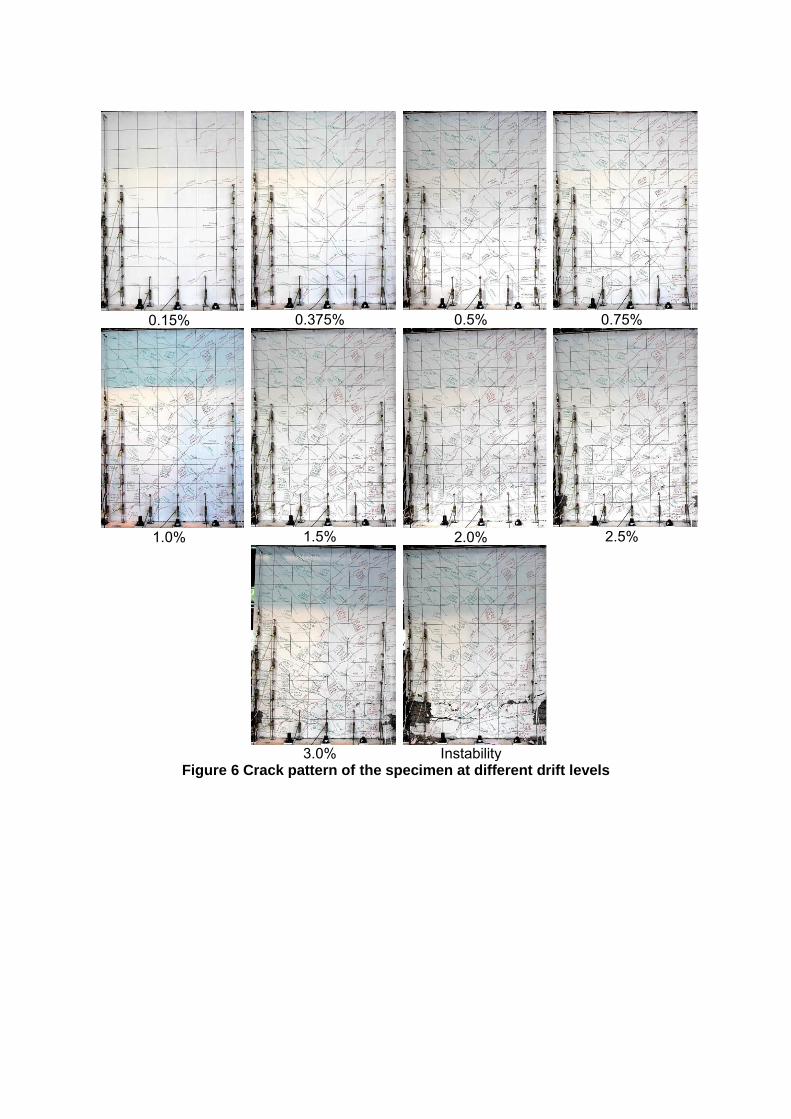
RESPONSE OF THE SPECIMEN Figure 6 displays the crack pattern of the specimen at different stages of loading. The grid size was 200x200mm. The specimen did not exhibit any cracking at 0.05% drift level and the first cracking happened at 0.06% drift and at about 550mm from the base during the 0.15% drift level. As can be seen in Figure 6, flexural cracks were distributed along the whole height of the specimen during the 0.15% drift level. The crack width was almost identical among all cracks (at about 0.04mm) at this stage. The number of horizontal cracks increased significantly at 0.375% drift level. These cracks were observed mostly along the boundary regions. A considerable number of diagonal cracks were also observed throughout the panel at this drift level. The distribution of crack width was almost uniform all over the specimen which can be attributed to the fact that the specimens represented the plastic hinge region of a four-storey
-4
-3
-2
-1
0
1
2
3
4
0 3 6 9 12 15 18 21 24 27 30
Dri
ft (
%)
Cycle Number.

wall. The cracks became wider and increased in number at 0.5% drift level. During the first cycle of 0.75%, a wide crack (1mm) happened at the base and extended up to 1150mm along the wall length (70% of the wall length). Another wide crack was observed at about 200mm from the base in the boundary region which did not extend more than 600mm along the wall length. According to the lateral load-top displacement response of the specimen this is the stage where overall yielding of the specimen happened. During the 1.0% drift level, the width of horizontal boundary region cracks increased considerably along 600mm from the base and the width of diagonal central region cracks increased within 1000mm from the base. Cover spalling was observed at the extreme compression end of the specimen during the 1st cycle of 1.0% drift level. At 1.5% drift level, new horizontal cracks formed in the boundary regions between former cracks which merged into wide diagonal cracks in the central region. This can be attributed to the difference in bar sizes of the boundary and central regions. At this stage, wide boundary cracks (with an average crack width of 1.3mm) were uniformly distributed within 700mm from the base. These cracks merged in the panel region and resulted in diagonal cracks that had an average crack width of 1.7mm. The initial out-of-plane displacement (1mm) occurred on the left boundary (i.e. the side in tension) during the 1st 1.5% drift cycle, and it increased in subsequent cycles. Quite a number of small cracks formed in the tension boundary at 2% drift; some of these cracks merged together to form wide cracks in the panel region. The wide cracks extended up to 50% of the wall height at this stage. No bar fracture or bar buckling was noticed until this stage and the out-of-plane displacement increased to about 7mm and 10mm in the 1st and 3rd cycles of 2.0% drift level, respectively. The crack pattern at 2.5% drift level was similar to the one at 2.0% drift level, and the crack width increased, particularly in the diagonal cracks. The wide cracks in the tension boundary region extended up to 1350mm from the base with a uniform distribution of crack width. When the load was reversed from the 2.5% drift level, the cracks in the tension region were wide open, and were still wide when the specimen was being reloaded in the opposite direction. Being spaced at an average distance of 120mm, these residual cracks had an average crack width of 0.7mm. At this stage, the out-of-plane deformation increased significantly in the compression boundary region and was clearly observable. Figure 7 displays the formation of out-of-plane deformation in the left boundary region during the second cycle of 2.5% drift level. Figure 7a indicates the wide cracks in the boundary region before initiation of out-of-plane displacement at 2.5% drift. Figure 7b and Figure 7c display development of the out-of-plane deformation at this drift level. Figure 7c indicates the maximum out-of-plane deformation and initiation of crack closure in one face of the wall at this drift level. This crack closure resulted in decrease of the out-of-plane deformation in the following stages (Figure 7d and Figure 7e) and its recovery (Figure 7f). The out-of-plane deformation did not recover completely at this stage since the compressive stresses increased in the inner face of the out-of-plane displacement profile (where the crack closure initiated) along with reloading in the opposite direction and resulted in concrete crushing in one face of the wall. The out-of-plane deformation increased in the right boundary element as well when the specimen was being unloaded and reloaded in the positive direction toward 3.0% drift level.
0.15%
0.375%
0.5%
0.75%
1.0%
1.5%
2.0%
2.5%
3.0%
Instability
Figure 6 Crack pattern of the specimen at different drift levels

(a)
(b)
(c)
(d)
(e)
(f)
Figure 7 Formation and recovery of out-of-plane deformation in the left boundary region, 2.5% drift level
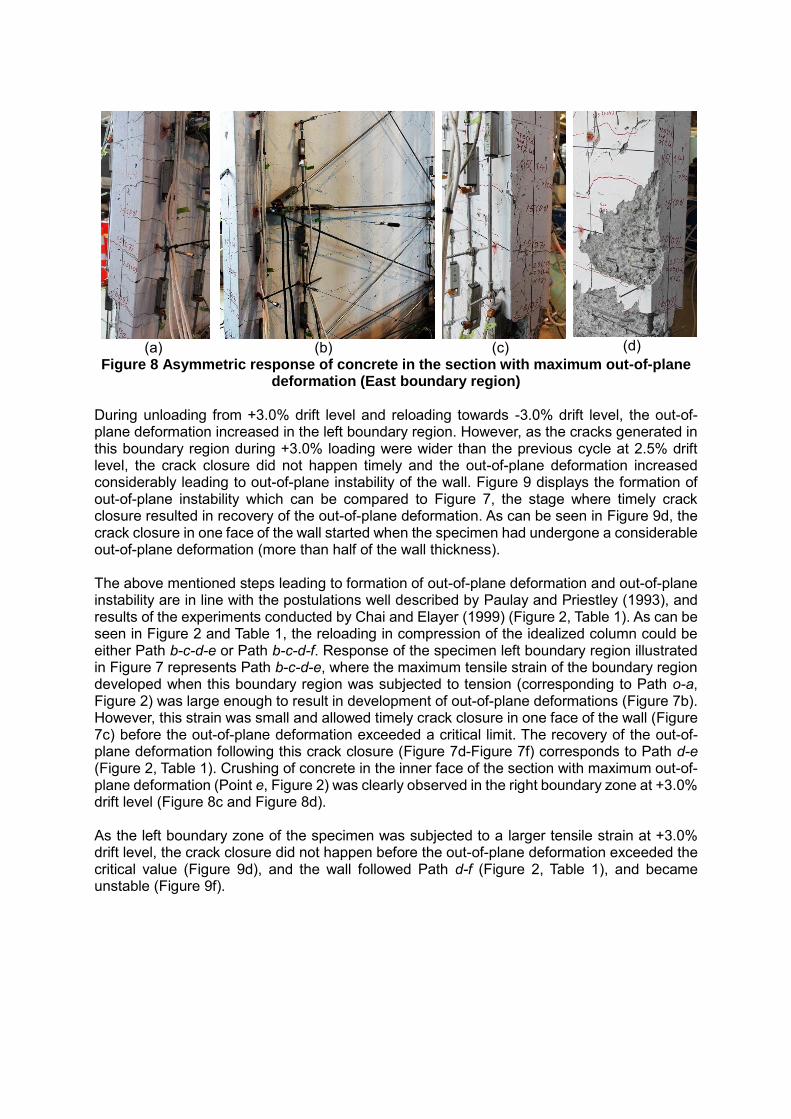
Following the same trend as the previous cycles, the out-of-plane deformation increased up to the state where the cracks started closing in one face of the wall. This crack closure resulted in increase of compressive stresses in one face of the wall and recovery of the out-of-plane deformation. Figure 8 indicates the asymmetric response of concrete in the section undergoing out-of-plane deformation. Figure 8a displays the stage where the crack closure has initiated in one face of the wall and the out-of-plane deformation is recovering. Further recovery of the out-of-plane displacement can be observed in Figure 8b. As can be seen in this figure, due to the out-of-plane deformation of the wall, the cracks are still open in one face of the compression boundary region while the cracks in the tension side of the wall have reopened. In other words, when the out-of-plane deformation increases in a boundary region that is under compression, the shear and flexural cracks of the inner face of the section with out-of-plane deformations close and the out-of-plane deformation starts to recover along with increase in top displacement applying further compression in the boundary region. At this stage, the cracks are still open in one face of the wall while the cracks in the tension side start to reopen (Figure 8b). At this stage, the inner face undergoes considerable compressive stresses due to the loading direction as well as the out-of-plane deformation of the boundary region. These increased compressive stresses can lead to cover spalling in inner face of the section with maximum out-of-plane deformation. Figure 8c indicates the colour flaking as an indication of cover spalling in inner face of the out-of-plane deformation section which was observed when the specimen was being unloaded from 3.0% drift level and Figure 8d displays the extent of cover spalling in this section at the end of the test.
(a)
(b)
(c)
(d)
Figure 8 Asymmetric response of concrete in the section with maximum out-of-plane deformation (East boundary region)
During unloading from +3.0% drift level and reloading towards -3.0% drift level, the out-of-plane deformation increased in the left boundary region. However, as the cracks generated in this boundary region during +3.0% loading were wider than the previous cycle at 2.5% drift level, the crack closure did not happen timely and the out-of-plane deformation increased considerably leading to out-of-plane instability of the wall. Figure 9 displays the formation of out-of-plane instability which can be compared to Figure 7, the stage where timely crack closure resulted in recovery of the out-of-plane deformation. As can be seen in Figure 9d, the crack closure in one face of the wall started when the specimen had undergone a considerable out-of-plane deformation (more than half of the wall thickness). The above mentioned steps leading to formation of out-of-plane deformation and out-of-plane instability are in line with the postulations well described by Paulay and Priestley (1993), and results of the experiments conducted by Chai and Elayer (1999) (Figure 2, Table 1). As can be seen in Figure 2 and Table 1, the reloading in compression of the idealized column could be either Path b-c-d-e or Path b-c-d-f. Response of the specimen left boundary region illustrated in Figure 7 represents Path b-c-d-e, where the maximum tensile strain of the boundary region developed when this boundary region was subjected to tension (corresponding to Path o-a, Figure 2) was large enough to result in development of out-of-plane deformations (Figure 7b). However, this strain was small and allowed timely crack closure in one face of the wall (Figure 7c) before the out-of-plane deformation exceeded a critical limit. The recovery of the out-of-plane deformation following this crack closure (Figure 7d-Figure 7f) corresponds to Path d-e (Figure 2, Table 1). Crushing of concrete in the inner face of the section with maximum out-of-plane deformation (Point e, Figure 2) was clearly observed in the right boundary zone at +3.0% drift level (Figure 8c and Figure 8d). As the left boundary zone of the specimen was subjected to a larger tensile strain at +3.0% drift level, the crack closure did not happen before the out-of-plane deformation exceeded the critical value (Figure 9d), and the wall followed Path d-f (Figure 2, Table 1), and became unstable (Figure 9f).

(a)
(b)
(c)
(d)
(e)
(f)
Figure 9 Formation of out-of-plane instability, 3.0% drift level CONCLUSIONS The experimental response of a rectangular wall specimen subjected to in-plane cyclic loading was discussed. Out-of-plane instability was the main and only failure pattern that was observed in the test, and the wall response was not influenced by other failure patterns such as bar buckling. Therefore, the observations could be used to scrutinize the mechanism of out-of-plane instability and the controlling parameters. The experimental observations regarding initiation, development and recovery of out-of-plane deformations as well as the out-of-plane instability of the specimen were in line with the observations presented in the benchmark research on development of out-plane instability in concrete columns representing the boundary zones of rectangular walls. The effect of residual strain of the reinforcement was well noticed by the crack pattern at different stages of loading. The out-of-plane deformation started at 1.5% drift level when the previously formed cracks did not close when the reloading in the opposite direction had started and recovered at the peak displacement in the opposite direction. However, the increase in the drift level resulted in wider cracks and consequently bigger values of out-of-plane deformations so that the out-of-plane deformation did not recover and changed into instability of the specimen at 3.0% drift level.

ACKNOWLEDGMENT The authors wish to acknowledge the financial support provided by the Ministry of Business, Innovation and Employment (MBIE) and the Quake Centre at University of Canterbury to conduct this research as well as the specimen fabrication scrupulously done by Bradford Precast. The considerate technician support provided by Alan Thirlwell at the University of Canterbury is highly appreciated. REFERENCES Chai, Y. and D. Elayer (1999). "Lateral stability of reinforced concrete columns under axial
reversed cyclic tension and compression." ACI Structural Journal 96(5). Dashti, F., R. Dhakal and S. Pampanin (2014a). Numerical simulation of shear wall failure
mechanisms. 2014 NZSEE Conference, Auckland, New Zealand, New Zealand Society for Earthquake Engineering.
Dashti, F., R. Dhakal and S. Pampanin (2015). Development of out-of-plane instability in rectangular RC structural walls 2015 NZSEE Conference, Rotorua, New Zealand, New Zealand Society for Earthquake Engineering.
Goodsir, W. J. (1985). The design of coupled frame-wall structures for seismic actions, University of Canterbury. PhD.
Johnson, B. (2010). Anchorage detailing effects on lateral deformation components of R/C shear walls, Master Thesis, University of Minnesota.
Oesterle, R. (1976). Earthquake Resistant Structural Walls: Tests of Isolated Walls, Research and Development Construction Technology Laboratories, Portland Cement Association.
Paulay, T. and M. Priestley (1993). "Stability of ductile structural walls." ACI Structural Journal 90(4).
Rosso, A., J. Almeida and K. Beyer (2015). "Stability of thin reinforced concrete walls under cyclic loads: state-of-the-art and new experimental findings." Bulletin of Earthquake Engineering, 1-30.
Sritharan, S., K. Beyer, R. S. Henry, Y. Chai, M. Kowalsky and D. Bull (2014). "Understanding poor seismic performance of concrete walls and design implications." Earthquake Spectra 30(1), 307-334.
Telleen, K., J. Maffei, J. Heintz and J. Dragovich (2012a). Practical Lessons for Concrete Wall Design, Based on Studies of the 2010 Chile Earthquake. 15th World Conference on Earthquake Engineering, 24-28 September 2012, Lisbon, Portugal.