outcrop mapping and photogrammetry of the precipice...
TRANSCRIPT

APPENDIX 4 EXTENSION OF PROJECT 7-0314-0228
2017
Outcrop mapping and photogrammetry of the Precipice Sandstone
ANLEC MILESTONE 8B FINAL REPORT: “INTEGRATED FACIES ANALYSIS OF EVERGREEN FORMATION“
Valeria Bianchi Fengde Zhou Joan Esterle
School of Earth and Environmental Sciences
The University of Queensland

1
This page is intentionally left blank

2
Title
Outcrop mapping and photogrammetry of the Precipice Sandstone
ANLEC Milestone 8B Report: Integrated facies analysis of the Evergreen Formation
Disclaimer
This report and the data on which it is based are prepared solely for the use of the person or corporation to whom it is addressed. It may not be used or relied upon by any other person or entity. No warranty is given to any other person as to the accuracy of any of the information, data or opinions expressed herein. The authors expressly disclaim all liability and responsibility whatsoever to the maximum extent possible by law in relation to any unauthorised use of this report.
The work and opinions expressed in this report are those of the Authors.
The authors wish to acknowledge financial assistance provided through Australian National Low Emissions Coal Research and Development (ANLEC R&D). ANLEC R&D is supported by Australian Coal Association Low Emissions Technology Limited and the Australian Government through the Clean Energy Initiative.

3
This page is intentionally left blank

i
Abstract
This objective of this project is to characterise the Evergreen Formation which is the regional seal
to the Precipice Sandstone. This project is included as additional scope to the ANLEC Project 7-
0314-0228 of the Precipice Sandstone as a geosequestration target in the Surat Basin. The
adopted workflow includes: (i) facies analysis of core, (ii) generation of a facies database (iii)
facies association interpretation and lateral variability of facies associations interpreted from
wireline logs, (iv) basin wide unit thickness maps and (v) development of a local model from
densely drilled area along depositional strike of the EPQ7.
The transition from the Precipice Sandstone to the Evergreen Formation is gradational and varies
laterally at a basin scale. The variation in the contact between the two formations reflects the
spatial variability of sedimentary facies and their projected geometries. Previous outcrop and
core studies subdivide the Precipice Sandstone into a lower and upper unit. The lower Precipice
Sandstone unit is described as blocky, and reflects its formation within large scale sand bars as
part of a braided river system. The upper Precipice is further defined by a series of stacked blocky
to fining upward sandstones often separated by fine-grained, thinly bedded units that are
interpreted to form baffles to flow. The lithological variations observed in the upper Precipice
Sandstone are interpreted to reflect its deposition within a meandering river system with variable
tidal influences, in a response to base level rise, drowning the system and depositing relatively
more suspended loads in the basin. This transition to suspended load-dominated sedimentation
forms the gradational contact between the Upper Precipice Sandstone and Lower Evergreen
Formation.
The Evergreen Formation can also be subdivided into lower and upper units by a marker horizon,
the Westgrove Ironstone Member. The ironstone is a chamositic oolite recognised regionally and
thought to represent a global depositional event. This marker is also thought to represent a
lower energy environment, close to a maximum flooding surface that can also be identified and
mapped spatially from seismic data. Beneath the ironstone marker is the Boxvale Sandstone
Member that is recognised as a sandstone dominated unit with variable thickness and character
across the basin. Where present, the Boxvale Sandstone Member varies in thickness from a few
metres to over 30 m. It is thickest in the northwest of the basin, forming an arcuate shape that
is interpreted to reflect deposition within a deltaic environment. This area appears disconnected
from sinuous belts also identified as Boxvale Sandstone that extend southeast and south across
the basin. Previous work recognised hummocky cross stratification in the northwestern
outcrops, along with southeast trending traction currents and northeast striking wave ripples.

ii
These sedimentary features are interpreted as wave reworked deltaic sediments which infill the
Evergreen lake or embayment. More recent work has suggested the extensive sandstone
dominated belts represented low stand fluvial deposits, which prograded eastward across the
basin. Disconnected sandstone belts of variable thickness, width and orientation also occur in
the underlying lower Evergreen Formation. Above the ironstone marker, the upper Evergreen
Formation is finer grained, thickening eastward, though still exhibiting sandier intervals that form
an easterly widening belt. The lithological variation from lower to upper Evergreen Formation is
interpreted to reflect a base level variation within a tidally influenced embayment that continues
to be fed from the northwest, with a laterally shifting depocentre.
Sedimentary logging of core material in the EQP7 area recognised the lower Evergreen Formation
by a series of stacked coarsening (and occasional fining) upward sequences, often capped by
paleosols, and culminating in the relatively ‘better sorted’ Boxvale Sandstone. These sequences
were interpreted as stacked distal and proximal mouthbars forming within a transgressive
systems tract. The ironstone marker represents the latest stage of regional regression, overlain
by a black shale that is thought to indicate the maximum flooding surface (MFS), or regional
topographic restriction on bottom water circulation. Above the ironstone marker, sediments are
interpreted as a continuation of more attenuated mouth bars that represent the onset of slow
regional regression, fully expressed within the Hutton Sandstone. These observations in core
support the interpretation of Green et al. (1997). A detailed local 3D model from wireline logs in
the APLNG Durham Ranch/Spring Gully area mimics a backward stepping fluvial-deltaic system
responding to a base level rise within a tidal to wave influenced environment. This change in
depositional systems within the upper Precipice Sandstone and Evergreen Formation are
responsible for the thickness, shape and connectivity of sandstone bodies to decline up
stratigraphy into shoreline parallel chenier plains.
This interpretation has implications on the Evergreen Formation as a reservoir-seal, as it suggests
lithological variation across the basin, though with fewer and more disconnected sandstone
bodies up-section. This understanding improves the quality of the stratigraphic variation up-
section, and also, potentially provides the basis of a secondary storage reservoir within the lower
part of the Evergreen or within the Boxvale Sandstone, that is capped by the finer grained sealing
unit of the upper Evergreen Formation.

iii
Table of Contents
Abstract ............................................................................................................................ i
Table of Contents ............................................................................................................ iii
Table of figures ................................................................................................................ iii
Introduction ..................................................................................................................... 0
Aims ................................................................................................................................. 0
Background ...................................................................................................................... 1
Summary of Precipice depositional evolution in 7-0314-0228 project ........................................ 2
Summary of Evergreen Formation ............................................................................................ 3
Facies analysis of Evergreen Formation strata ................................................................... 3
New data from core logging ...................................................................................................... 3
Chinchilla-4 ...................................................................................................................................... 4
Woleebee Creek-GW4 .................................................................................................................... 7
West Wandoan-1 (WW-1)............................................................................................................... 8
Palaeocurrents from WW-1 image log: ........................................................................................ 10
Correlation between cores ........................................................................................................... 12
Geological modelling of the Evergreen Formation ........................................................... 14
Data ....................................................................................................................................... 14
Regional formation thickness ................................................................................................. 15
Detailed Model ...................................................................................................................... 17
Discussion ...................................................................................................................... 22
Summary ........................................................................................................................ 25
Future work ................................................................................................................... 25
References ..................................................................................................................... 26
Appendix 1 ..................................................................................................................... 28
Appendix 2 ..................................................................................................................... 31
Variogram Analysis ................................................................................................................. 31
Distribution of GR .................................................................................................................. 33
Table of figures Figure 1: Inset of study outcrop area of the Precipice Sandstone and location CTSCo Glenhaven
Project Area (West Wandoan-1). Stratigraphic column is after Hamilton et al., 2014. ......................... 0
Figure 2: Three scale of observation used in FAKTS database (Colombera et al, 2012)......................... 2
Figure 3: Sketch for the depositional evolution of Precipice Sandstone (Bianchi et al., 2016) .............. 3
Figure 4: Sedimentological log and interpretation of Chinchilla-4 core. ................................................ 6

iv
Figure 5: Sedimentological log and interpretation of depositional environments of Woleebee Creek-
GW4 core. ............................................................................................................................................... 8
Figure 6: Photographs of West Wandoan-1 A) glauconitic sandstone and dark siltstone, B) oolitic
sandstone, C) Close-up of ooids in dark matrix. ..................................................................................... 9
Figure 7: Sedimentological log of the West Wandoan-1 core, interpretation of depositional
environments and rose diagram indicating the paleoflow of each facies association (Bianchi et al.,
2016). .................................................................................................................................................... 11
Figure 8: Correlation panel of Evergreen Formation between West Wandoan-1 (WW-1), Woleebee
Creek-GW4 (GW4) and Chinchilla-4 (Ch 4). Flattened at the Westgrove Ironstone Memebr
occurrence. Yellow marks Boxvale Sandstone Member and green one the Westgrove Ironstone
Member. ............................................................................................................................................... 13
Figure 9: Location of Durham Ranch and Spring Gully (APLNG) areas in Surat Basin (a) and locations
for wells and six correlation sections. b) background isochore is unit thickness for Lower Precipice,
from Bianchi et al., 2016 (Project report 7-0314-0228). ...................................................................... 14
Figure 10. Isochore along pillars for the formation Evergreen Lower on the left-hand side picture.
Circle points are well markers picked for the Evergreen Upper. In the right-hand side figure is the
sand% for the Evergreen Lower, intersected by 534 wells. Note that unit thickness maps were based
on the picks and sand% map based on the wellbores with log interpreted lithology. ........................ 15
Figure 11. Isochore along pillars (left-hand side figure) and sand% (right-hand side figure) for the
formation Boxvale Sandstone. Circle points are well markers picked for the Evergreen Upper. ........ 16
Figure 12. Isochore along pillars (left-hand side figure) and sand% (right-hand side figure) for the
formation Evergreen Upper (a). Circle points are well markers picked for the Evergreen Upper. ...... 17
Figure 13: Two sectional views of well correlation, wireline log of GR (Track #2) and interpreted
lithology (Track #3). Locations of sections (a) PS1 (N-S) and (b) PS5 (E-W) were shown in Figure 9. .. 18
Figure 14: Structural elevation on the top of Evergreen for the APLNG model. .................................. 19
Figure 15: Cell height in (a) Evergreen Upper, (b) Boxvale Sandstone and (c) Evergreen Lower. ........ 19
Figure 16: Upscaled GR (10x vertical exaggeration) and horizon at the top of the Precipice Sandstone.
.............................................................................................................................................................. 20
Figure 17: Comparison of histogram for GR from wireline log and upscaled cell. (a) Evergreen Upper;
(b) Boxvale Sandstone; and (c) Evergreen Lower. ................................................................................ 20
Figure 18: Generated 3D distribution of GR. ........................................................................................ 21
Figure 19: Filtered GR distribution (<80) in the (a) Evergreen Upper, (b) Boxvale and (c) Evergreen
Lower formations. ................................................................................................................................. 21
Figure 20: Summary panel of formations studied within this project. Lower and Upper Precipice units
thickness maps are from Bianchi et al., 2016. Paleocurrents derive from outcrop measurements and
image logs. Paleocurrents for Lower Evergreen and Boxvale Sandstone units were measured in West
Wandoan-1, but also include observations from Fielding (1990)......................................................... 24
Figure 21: Horizontal variogram map for the upscaled GR shows a major range orientation of 135˚
from north. ............................................................................................................................................ 32
Figure 22: Semivariance with distance in the vertical direction for the (a) Evergreen Upper, (b)
Boxvale, and (c) Evergreen Lower. ........................................................................................................ 33

0
Introduction The prediction of the subsurface movement of injected CO2 is based on a geological model of a
siliciclastic sedimentary succession that forms the framework of a reservoir/sealing system for a given
injection site. The model is based on geological, petrophysical and engineering judgement.
Sedimentological studies of the targeted reservoir/seal pair of the Precipice Sandstone and overlying
Evergreen Formation within the CTSCo Glenhaven storage complex aim to inform these models which
in turn predict CO2 movement and containment. Geological studies of the target reservoir system
provide conceptual models of the distribution of lithologies that influence porosity, permeability and
spatial connectivity of flow paths critical to CO2 injection.
Fluid flow, at the pore scale, is determined from core analyses of different lithologies that exhibit
varying textures and bedding characteristics, which vary between sedimentary facies. Although facies
models, which provide an overall summary of a particular sedimentary environment (Walker, 1984),
are a dated concept, they still form the backbone of reservoir flow unit identification and reservoir
modelling, becoming more effective with continuous innovation (Howell et al., 2008; Martinius et al,
2014). Where these different facies can be identified in wireline log signatures, their lateral extension
and juxtaposition to other facies can be mapped and modelled. Where units are exposed in outcrop,
their continuity and interrelationships can be mapped, and the information used to inform modelling
and conceptualisation of subsurface drilling data. It is through this general process that small scale
features and their potential reservoir behaviour is upscaled into the larger field scale. Core from West
Wandoan-1, Woleebee Creek-GW4 and Chinchilla-4 drill holes were logged for this purpose (Figure 1).
The first part of this study focussed on the Precipice Sandstone (Bianchi et al, 2016), and this extension
study examines the overlying Evergreen Formation.
Figure 1: Inset of study outcrop area of the Precipice Sandstone and location CTSCo Glenhaven Project Area (West Wandoan-1). Stratigraphic column is after Hamilton et al., 2014.
Aims The relationship with the underlying Precipice Sandstone is of gradual transition, which makes difficult
a clear distinction between reservoir and seal. The main aim of the extension project was to
investigate with higher detail the facies of the Evergreen Formation and its depositional history, in

1
order to have a deeper understanding of the lithological associations, geometries and dimensions of
the sealing unit. The Evergreen Formation contains the Boxvale Sandstone Member that is overlain by
the Westgrove Ironstone Member, of which forms a regionally persistent horizon across the basin,
above which the lithological characteristics of the formation changes. The members (Boxvale
Sandstone and Westgrove Ironstone) that certainly affect the sealing potential within the Evergreen
Formation, require a high-resolution sedimentological investigation to characterise dimensions and
geometries of these disturbances. A further aim was testing the existent facies scheme and modifying
the scheme, where needed, for the overlying Evergreen Formation. The facies scheme and
interpretations developed in ANLEC Project 7-0314-0228 for the Precipice Sandstone were applicable
for every outcrop observed. They assisted in the recognition of sedimentary facies in core and their
assignment to a depositional environment with spatial dimensions applicable to static geological
modelling of the Precipice Sandstone target reservoir, and the potential for compartmentalisation
resulting from finer grained units. The deliverable of this milestone is a integrated facies analysis of
the Evergreen Formation.
Background The Precipice Sandstone and Evergreen Formation have been studied for their reservoir/sealing
properties for hydrocarbons (Martin, 1976), groundwater (summarised in QWC, 2012), CO2
geosequestration (Hodgkinson et al., 2010), and water reinjection (APLNG, 2013). The Precipice
Sandstone is exposed in an extensive outcrop or “sandstone belt” that forms the northern rim to the
Surat Basin (Figure 1). The Precipice outcrop is sufficiently laterally extensive to enable facies changes
to be observed at different locations. These changes are interpreted to reflect regional changes across
the palaeo-topographic highs to lows, which can be used to calibrate the dimensions and hydraulic
flow of mappable facies. These facies correspond to changes in grain size, rounding and sorting (and
subsequent diagenesis), affecting porosity within the Precipice Sandstone which in turn varies both
vertically and laterally (Bianchi et al, 2016). This can create internal baffles for CO2 migration as the
reservoir top seal is approached.
The fine-grained nature of the Evergreen Formation and susceptibility to weathering and erosion
precludes its extensive expression in outcrop, therefore facies characterisation must be conducted
through subsurface drilling and core. The facies database proposed in the Project 7-0314-0228 is
organised by facies code, name of the facies, description of grain size, sedimentary structures
(pattern), trend and accessories (as roots, plant debris or bioturbation), interpretation of deposits and
dimension in outcrop. The facies association provides a sub-environment description. For instance,
channel belt and flood basin belong to continental settings, whereas shoreline, Gilbert delta and shoal-
water delta populate transitional coastal settings. Deposits and associated depositional environment
were interpreted following Bull (1999), Miall (1996), and Bridge (2003) for fluvial-alluvial settings; and
Nemec (1990), Reading (2004), Olariu & Batthacharya (2006) and Dumas & Arnott (2006) for
transitional coastal deltaic and non-deltaic settings. These facies were applicable to all of the outcrops
in the Precipice Sandstone and assisted in assigning environments and their spatial dimensions from
core.
The integration of elements as facies units, architectural elements, sub-environments and
depositional environments provides the workflow that can be coded into a quantitative database for
application to reservoir modelling (Colombera et al, 2013). The use of these types of databases

2
enhance information transfer between real and virtual geological observations, and provide a range
of scenarios for application within a reservoir, that can be verified through model validation (Figure
2). The facies tables are provided as an appendix at the end of the document; one facies code has
been added to the previous facies database to account for the oolitic Westgrove Ironstone Member.
Figure 2: Three scales of observation used in FAKTS database (Colombera et al, 2012)
Summary of Precipice depositional evolution in 7-0314-0228 project Despite the common interpretation of purely fluvial deposition of the Precipice Sandstone (Fielding et
al. 2006; Ziolkowski et al., 2014), field trips conducted as part of Project 7-0314-0228 shed some light
on the complexity of the depositional environment on the eastern outcrops. As a result, the Precipice
Sandstone was subdivided into two allounits (Figure 3).
The lower allounit was described as:
• sand-dominated deposited from multi-channel braided to meandering fluvial system,
detected both in outcrop and in the subsurface.
The deposits of the upper allounit were described as:
• coastal deltaic environment (e.g. Gilbert delta in the Flagstaff area and shallow water delta in
the Carnarvon and Cracow area), and;
• wave-dominated coastal environment (in the Isla Gorge and Forest Hill area) in outcrop and
tidal influenced meandering fluvial system in the subsurface.
The transition between these two allounits is marked by a sea/lake level transgression, which due to
the low gradient of the basin had to be almost immediate across the basin, making it a good candidate
for a boundary surface between the two allounits. The transgression was interpreted as coming from
the north based on paleocurrents of upper-allounit delta complexes on the eastern flank of the
outcrop.
Observations of the lower braided fluvial facies were exposed best at Carnarvon Gorge, where
discrete, finer grained units could be tracked for about 2 km. This suggests that the finer grained units
of the braided river facies can be correlated, or at least modelled at the kilometre scale. From the
regional model, a "baffle free" belt trending southeast was present and, coupled with southerly
marching, cross bedded bar forms in the lower unit, may act to control flow pathways in the reservoir.
The observed shift in palaeocurrent direction and flow energy creates increased heterogeneity within

3
the system stratigraphically upward, and eastward across the basin that, in turn impacts upon porosity
and permeability in different areas of the basin.
Figure 3: Sketch for the depositional evolution of Precipice Sandstone (Bianchi et al., 2016)
Evergreen Formation introduction The Evergreen Formation has been previously studied by Mollan et al. (1974) and Exon (1976), by
which it is divided into a Lower Evergreen (100 m thick), the Boxvale Sandstone Member (50 m thick),
the Westgrove Ironstone Member (5 m thick) and the Upper Evergreen (12 m thick). These thickness
values vary across the basin. Excluding the internal members, the lithologies overall are fairly
consistent, dominated by siltstone and argillaceous fine sandstone with abundant lithic and feldspar
grains and carbonaceous shales. The sandstone is considered relatively impermeable due to the
presence of argillaceous matrix and/or ferruginous cement.
The Evergreen Formation incorporates a localised sand-dominated body called the Boxvale Sandstone
Member, interpreted as a prograding delta (Fielding, 1990) or an incised-valley system (Ziolkowski et
al., 2014), and the Westgrove Ironstone Member, which is a semi-continuous layer in the basin,
consisting of chamositic oolitic concretions, formed during a period of relative stability in the basin
(Mollan et al., 1972). These latter features in the Evergreen Formation support the interpretation of a
continental transgression transitioning to marine environments at the top of the Formation
(Ziolkowski et al., 2014; Exon, 1976; Mollan et al., 1972), however, Fielding (1990) suggested the open
body of water was lacustrine. Understanding the spatial extent of this transgression has implications
upon the inferred subsidence and paleogeographic evolution of the basin.
Facies analysis of Evergreen Formation strata
New data from core logging With the aim of investigating the Evergreen Formation in continuous section, two additional cores
were logged to support the West Wandoan-1 interpretation. These two cores were Chinchilla-4,
located 5 km South of Chinchilla township, and Woleebee Creek-GW4, located 30 km west of the West
Wandoan-1 well, Figure 1. These two cores were logged at the Zillmere Exploration Data Centre, a
(Department of Natural Resources and Mines) DNRM facility. The cores were logged to provide
information on the transition between the Precipice Sandstone and Evergreen Formation that was not
cored in the West Wandoan-1 well. The Evergreen Formation has been generally attributed to a

4
fluvial-lacustrine to restricted embayment depositional environment, but there are a myriad of
depositional environments with deposits, characterised by different grain-size distribution and
sedimentary structures. These facies exhibit different geometries that in turn influence the
heterogeneity of the sealing unit. All depths in the report refer to driller’s depth (measured depth RT).
Chinchilla-4
The Precipice Sandstone was subdivided into the Lower and Upper Precipice following Green et al
(1997) and Ziolkowski et al (2015). The Lower Precipice is dominated by the coarse to medium
grained, cross bedded, quartzose sandstone, interpreted as a braided river facies. This unit transitions
upward into a series of medium to fine grained sandstones that fine upward and are mapped by the
above authors as Upper Precipice. The transition from the Upper Precipice Sandstone to the
Evergreen Formation is gradual, thus a distinctive pick for the Evergreen base is not always easy to
recognise, not always present, or is included stratigraphically as part of the Lower Evergreen. For the
purposes of this study, the base of the upper Precipice is interpreted at driller’s depth 1159.60 mRT
(Figure 4). The presence of tidal influenced facies becoming more evident in these sediments, has led
to the proposed upper Precipice limit for the West Wandoan-1 core. The top of the Evergreen
Formation is interpreted at 983.21 m (driller’s depth) which is consistent with sedimentological
observation in the core; the top is marked by an erosional surface, in which rip-up mud clasts from
the underlying strata, indicate the start of the Hutton Sandstone.
Generally, the Evergreen Formation in Chinchilla-4 exhibits a rhythmic alternation between medium
sand and organic-rich mudstone and siltstone. The Formation has been recognised completely, such
as lower Evergreen, Boxvale Sandstone Member, Westgrove Ironstone Member, and upper
Evergreen. The lower and the upper Evergreen present an alternation between fine to very fine
sandstone and organic-rich mudstone and siltstone. Sandstone is composed of quartz, k-feldspar and
black mica; sometimes the sorting of the minerals indicates a mixing of different compositional
sources that have a different behaviour during transport processes due to their density. They are
characterised by ripple cross-lamination and plane-parallel stratification, sometimes with ripples,
combined flow ripples, and mud drapes present on the top, indicating a combination between
oscillatory and current flow, as well as variable energy process of deposition. Locally mud-clast beds
are recognised in the sandstone packages. The packages have a mostly fining-upward trend and with
an average thickness of 5 m. Organic-rich mudstone and siltstone are frequently intercalated with very
fine sand with ripples or lamination, indicating a variable low-energy environment. Often, fine-grained
sediments are burrowed with a medium or high degree of bioturbation. Present are planolites,
horizontal small burrows within intralamination, indicating a stressed environment in the water
chemistry; glossifungites, horizontal circular burrows infilled with sand and cased in mudstone,
indicating a grazing behaviour in a coastal environment; and skolithos, vertical burrows, indicating
escaping behaviour or grazing in a sandy shore. Synaeresis cracks are also present in mudstones that
can be confused as bioturbations, but as distinctive feature they have dishomogeneous diameters.
They usually represent a change in water salinity that affects the fluidification of the mud (Burst,
1965).

5
Some very thin in-situ coal layers (5 – 7 cm thick) are deposited in the lower Evergreen Formation,
whereas in the upper Evergreen Formation, root penetration is evident but with no development of
coal in this particular core.
The Boxvale Sandstone Member is characterised by very clean, well-sorted sandstone (from 1084 to
1050.25 mRT with thickness of ~34 m). Due to the fact that is well sorted, it does not exhibit
sedimentary structures. The Westgrove Ironstone Member (1.5 m thick) is characterised by red
ironstone (chamositic) rich ooids of similar millimetre size in a micritic matrix. The origin of these
sediments may be associated with a shallow, wave-dominated environment, though probably
reworked in a low-energy environment, which facilitates mixing between ooids and muds. These
ooids are not just present in the Westgrove Ironstone Member, but are also deposited intercalated
with mudstone as singular grains or mixed with fine sandstone for 22 m of section above the Boxvale
Sandstone, in the prodelta association. The presence of a structureless black shale above the oolitic
succession indicates a particularly restricted offshore marine environment, that is expected to be
laterally continuous and found in core in other wells.
6
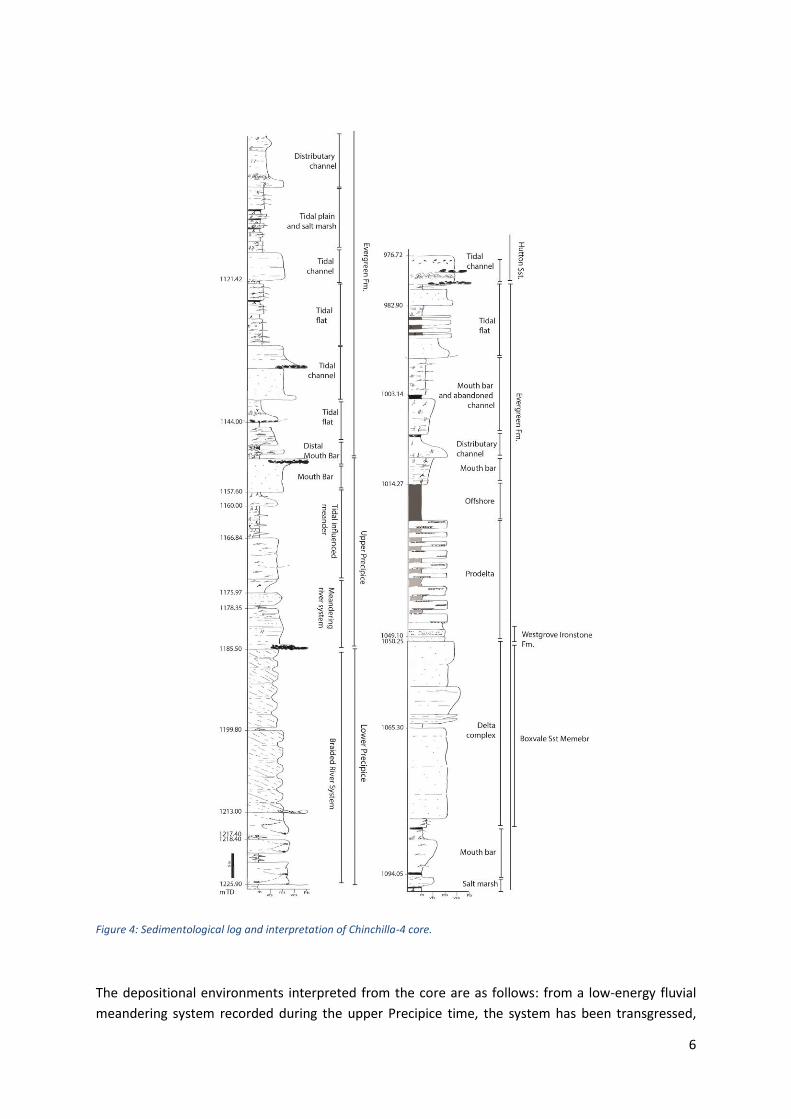
Figure 4: Sedimentological log and interpretation of Chinchilla-4 core.
The depositional environments interpreted from the core are as follows: from a low-energy fluvial
meandering system recorded during the upper Precipice time, the system has been transgressed,

7
leading to a coastal transitional environment, potentially a tidally-influenced meandering plain, which
then develops toward a tidal plain with channels and salt marshes. These tidal flat settings are strictly
associated with distal mouth bars, and are represented by facies with close spatial relationships. The
distal mouth bars develop in proximal mouth-bar delta complexes with associated distributary
channels overlying the proximal mouth bar in an overall regression.
Woleebee Creek-GW4
Located within EPQ7, Woleebee Creek-GW4 records the thickest section of Precipice Sandstone and
Evergreen Formation in all of the cores described in this study (Figure 5). Similar to West Wandoan-1
and Chinchilla-4, the Evergreen Formation is characterised by a variety of depositional environments,
always reflecting a transitional coastal environment. The base of Evergreen is interpreted at 1436.78
mRT (driller’s depth); the Boxvale Sandstone Member from 1356.35 m to 1338.36 mRT, and the top
of the formation at 1272.74 mRT (base of the Hutton Sandstone).
In contrast to Chinchilla-4, this core represents a more sandstone-dominated lower Evergreen
Formation. Sandstones are clean and well sorted with low angle plane parallel stratification, indicating
a beach-ridge environment. This facies transitions directly into back-barrier salt marshes,
characterised by often sulphurous coal deposits. Like Chinchilla-4, coal layers are present in the Lower
Evergreen Formation, whereas in the Upper Evergreen Formation root penetration is seen but no
development of coal. Sandstone is organised in combined-flow ripples and intercalated with mud
layers that present bioturbation (planolites, skolithos and glossifungites), in the same association seen
in core of Chinchilla-4. The Boxvale Sandstone Member is characterised by clean and continuous
poorly bedded sandstone, which gradually transitions into fine, darker sandstone, mixed with ooids.
The Westgrove Ironstone Member is evident in the core at 1324.30 mRT, as a highly oxidized and
compacted oolitic layer. Ooids here are present exactly as Chinchilla-4 mixed with sand or in pockets;
some exhibit sedimentary compactional deformation in this core. The presence of thicker
structureless black shale above the ooilitic succession, at the same stratigraphic point of the
succession as Chinchilla-4, can be correlated with the restricted offshore marine environment and
corroborates the expectation that this allounit it is laterally continuous.
Interpretation of the depositional environment does not differ from Chinchilla-4. From a low-energy
fluvial meandering system recorded during the upper Precipice time, the system has been
transgressed, leading to a coastal transitional environment. The low-energy river plain develops to a
tidal plain, with channels and salt marshes. Moving upward the tidal plain shifts to a tidal flat with
sediment supply sourced from distal mouth bars, up into the proximal mouth bar delta complex,
capped by a shallow wave dominated environment. As in other areas of the basin this core exhibits a
restricted marine setting that occurs above oolites, highlighting a maximum flooding surface and the
initiation of a regression with progradation of distal mouth bars up to distributary channels (at the
base of the Hutton Sandstone). The frequent occurrence of slumps and soft deformation indicates
increased sediment supply in a water-saturated environment where mouth bars had developed.

8
Figure 5: Sedimentological log and interpretation of depositional environments of Woleebee Creek-GW4 core.
West Wandoan-1 (WW-1)
Core was acquired from the base of the Precipice Sandstone to the Hutton Sandstone. For the
purposes of this study, the core was logged at low resolution down to 938 mRT (middle Hutton
Sandstone), and at high resolution down to 1146 mRT. Although coring was continuous, approximately
85 m of the upper Precipice allounit and its transition to the Evergreen was not cored due to
operational issues. Overall, the core presents facies belonging to a fluvial-alluvial depositional setting
and passes upward to transitional, to brackish and marine deposits (Figure 7).
The Evergreen Formation starts at 1061.19 mRT with quartzose, well-sorted, clean structureless
sandstone, some of the packages show a slight plane parallel or slightly inclined planar cross
stratification (facies 18b, 11 and 12), indicating a wave-dominated environment. The following
succession (from 1051 mRT) is dominated by intercalation of bioturbated mud and fine rippled
sandstone with coal and root penetrated horizons, organized in small coarsening-upward packages
(facies 19, 20b and 16). Mud becomes predominant with soft-deformation (facies 20a) intercalated
with minor combined rippled sandstone (f14). Burrowing is from vertical to small horizontal types
(skolithos to planolites) going up section, indicating a transition between proximal to distal mouthbar
and lower shoreface / offshore-transition deposits. These facies associations indicate the presence of
a river mouth with “environment deepening” such as from proximal to distal. The presence of lower
shoreface and offshore transitional facies indicates the influence of wave action on a fluvial-
dominated deltaic coast. This wave influence is also confirmed by a thin layer of coarsening sand,
transitioning gradually into well-sorted sandstone bodies (facies 11 and 12), immediately followed by
intercalation of glauconitic sandstone and silty mudstone (1025 to 1011 m). Glauconite has been

9
recognized in hand specimen and confirmed by XRD analysis (Farquhar, 2013; G. Dawson pers. comm.)
The glauconitic sandstones have variable colour from green to black, indicating an increasing degree
of water column starvation (Dumas and Arnott, 1999) and little to no additional sediment supply, and
is interpreted as an offshore environment marking the end of the lower Evergreen Formation (Figure
6A).
Figure 6: Photographs of West Wandoan-1 A) glauconitic sandstone and dark siltstone, B) oolitic sandstone, C) Close-up of ooids in dark matrix.
The Boxvale Sandstone Member starts at 1011 mRT with a gradual coarsening upward sequence,
initiated by a series of small coarsening-upward sequences including slumped fine sandstone bodies
in muds presenting liquefaction features (f19 and f20a). The Member coarsens upward with massive
argillaceous sandstone and rare plane parallel stratification highlighted by fragmented organic
laminae for a thickness of 7 m, up to 1001 mRT (facies 18b). This facies association is interpreted to
be an extensive delta complex.
Immediately above this depth the core records a deepening expressed by the occurrence of mudstone
and minor intercalation of slumped sandstone, representing the upper Evergreen. In this
interpretation, the upper Evergreen includes the Westgrove Ironstone Member. The degree of
bioturbation increases from vertical to horizontal with great variability in size, indicating a deeper
brackish to marine environment. One sandstone package within the bioturbated mud shows
hummocky cross-stratification indicating offshore transition (f15). The oolites float in a dark brown
muddy micritic matrix, which is contrary to the accepted origin of medium to high-energy coastal
environments, thus, these ooids are considered to have been re-worked by wave influence into a
deeper environment. The rusty-oxidized appearance of this layer is most likely due to some water
influx of different chemistry. This facies is not present in the facies database presented in the project
7-0314-0228, therefore a new facies code was generated (f22). XRD analysis conducted on the sample
at UQ demonstrated the presence of glauconite, siderite (Mg and Ca dominated) and hydrothermally
altered minerals (Farquhar, 2013; Dawson et al., 2016) which may suggest a secondary contamination
from surrounding fluid movement, probably instigated by hydrothermal activity.
Above 997.21 mRT the facies sequence infers a deeper environment characterized by black shale,
organic rich mud with rare to absent horizontal bioturbation and some plant debris, some minor thin

10
fine-grained sandstone is present in combined-flow ripples (facies 16 and 14). Here are present also
synaeresis cracks (Burst, 1989). These facies are interpreted as restricted marine, offshore deposits
and lower shoreface in a wave-dominated coastal environment up to 955.80 mRT, which marks the
base of the Hutton Sandstone. At this depth, a sharp erosional surface floors the massive medium
sandstone, which hosts fragments of mudclasts belonging to the underlying succession; these are
identifiable from the degree of bioturbation of the laminated black mudstone.
Palaeocurrents from WW-1 image log:
Palaeocurrents for the West Wandoan-1 image log have been measured and were presented in the
previous report for project 7-0314-0228. The rose diagrams, determined from picking sinusoids
within the different facies association of the Evergreen Formation are shown in Figure 7. It is worth
noting that for the lower Evergreen Formation a dominant northward direction occurs, consistent
with the northward direction of the coastal environments recognised in the outcrops for the upper
Precipice on the eastern side of the basin. This is in contrast to the Boxvale Sandstone Member
where an eastward direction of sediment dispersal is interpreted from the WW-1 image log.

11
Figure 7: Sedimentological log of the West Wandoan-1 core, interpretation of depositional environments and rose diagram indicating the paleoflow of each facies association (Bianchi et al., 2016).

12
Correlation between cores
A stratigraphic correlation of the cores from the studied wells is shown as Figure 8 datumed on the
Westgrove Ironstone Member. The cores are arranged spatially from west to east. The thickness of
the West Wandoan-1 core appears thinner than the other cores; the reason being that 85 m, of
section from the upper Precipice Sandstone and lower Evergreen Formation was not cored. In
reality the lower Evergreen interval in West Wandoan-1 is thicker than in GW4, due to vertical
stacking of mouth bars. The lower Evergreen Formation thins eastward and appears to be
characterized by tidal settings rather than a deltaic complex. The Boxvale Sandstone is represented
by a proximal delta complex, which has a thicker expression at Chinchilla-4 in the southeast. The
Westgrove Ironstone Member always occurs above the Boxvale Sandstone but the isopach between
the two differs at different localities. The significance of the Westgrove or of the chamositic oolites
above a delta complex suggests different depositional models. Although evidence for the formation
of ferruginous ooids in marine environments in the literature is not strong (Young, 1989), it is not
excluded. The more likely depositional models are:
(1) The generation of the ferruginous allochems in the nearshore, probably restricted lagoonal
environments during periods of low sea level stand and their reworking into the basin of deposition
by storms or during a subsequent transgressive event (Bayer 1989; McGhee & Bayer 1985).
(2) The development of oolitic ironstones on offshore swells which receive little clastic sediment, but
on which the sediments may be intensely reworked by wave activity (Hallam 1975).
(3) The in-situ development of ooids on marine shelves during phases of sediment starvation, such
as that produced by rising sea level (Young 1989).
These models may not necessarily contradict each other; we consider indeed that these three
models can be applicable to the Westgrove Ironstone Member depositional setting.
The upper Evergreen is thick in GW4 and Chinchilla-4, characterized by thick black shale that is
mappable across the basin with similar thickness, and by vertical stacking of mouth bars.

13
Figure 8: Correlation panel of Evergreen Formation between West Wandoan-1 (WW-1), Woleebee Creek-GW4 (GW4) and Chinchilla-4 (Ch 4). Flattened at the Westgrove Ironstone Memebr occurrence. Yellow marks Boxvale Sandstone Member and green one the Westgrove Ironstone Member.

14
Geological modelling of the Evergreen Formation
Data In this study, two scales of structural model were built: a regional model based on the updated well
markers made available to UQ from the Office of Groundwater Impact Assessment (OGIA; Sliwa,
2017), and a local model in the densely drilled APLNG Durham Ranch and Spring Gully CSG Fields.
These models were used to create unit thickness maps, coupled with sandstone percentage based on
wireline logs, within the different members of the Evergreen Formation. The calculation of sandstone
percentage at the regional scale was based on the wireline log interpreted lithology from Sliwa (2017).
The Durham Ranch/Spring Gully model used normalised Gamma Ray (GR) logs that were statistically
analysed to develop variograms that guided the interpolation of GR using Kriging. The resulting GR
property model was filtered (using an API of ~70) to identify and illustrate the geometry of low GR
geobodies that represent sandstones.
Table 1 lists the horizons and number of well markers used in the model. In addition, 90 wells from
the densely drilled Spring Gully Field area (~10×20 sq. km) were used to create the local model in
which to examine variation in lateral continuity of sandstone bodies in the Evergreen Formation
(Figure 9)
Table 1. Horizons and well marker numbers for the regional model.
Formation tops Wells with tops
Evergreen Upper 1124
Boxvale Sandstone 372
Evergreen Lower 1053
Lower Precipice 1220
Figure 9: Location of Durham Ranch and Spring Gully (APLNG) areas in Surat Basin (a) and locations for wells and six correlation sections. b) background isochore is unit thickness for lower Precipice, from Bianchi et al., 2016 (Project report 7-0314-0228).
PS1'
PS2'
PS3'
PS4'
PS5'
PS6'
149°02'E 149°04'E 149°06'E 149°08'E 149°10'E 149°12'E
149°02'E 149°04'E 149°06'E 149°08'E 149°10'E 149°12'E
26°0
4'S
26°0
2'S
26°0
0'S
25°5
8'S
25°5
6'S
25°5
4'S
26°04'S26°02'S
26°00'S25°58'S
25°56'S25°54'S
0 1 2km
EPQ7
Chinchilla
DALBYKogan
Roma
Taroom
Wandoan
147°30'E 148°00'E 148°30'E 149°00'E 149°30'E 150°00'E 150°30'E 151°00'E 151°30'E
147°30'E 148°00'E 148°30'E 149°00'E 149°30'E 150°00'E 150°30'E 151°00'E 151°30'E
28°4
8'S
28°2
4'S
28°0
0'S
27°3
6'S
27°1
2'S
26°4
8'S
26°2
4'S
26°0
0'S
25°3
6'S
25°1
2'S
24°4
8'S
28°48'S28°24'S
28°00'S27°36'S
27°12'S26°48'S
26°24'S26°00'S
25°36'S25°12'S
24°48'S
0 25 50km
05101520253035404550556065707580859095100105110115
Thickness (m)
(a)
(b)
EPQ7Reedy Creek
N
Geological modelling boundary
Borehole
Isla Gorge 2
Nathan Gorge
Well correlation section
Unit
Low
er
Pre
cip
ice
San
dst
on
e

15
Regional formation thickness Thickness and sandstone percentage maps are shown for the Evergreen lower (Figure 10), Boxvale
Sandstone (Figure 11) and upper Evergreen (Figure 12). In these maps, the lower Evergreen is the
interval from the bottom of Boxvale to the top of the lower Precipice Sandstone. Figure 13 shows
the correlation of those three units, and GR and lithology features. Note that these maps will
continue to change, as more data become available, but their patterns reflect potential generalised
environments of deposition that can be tested against the core descriptions.
Figure 10. Isochore along pillars for the lower Evergreen on the left-hand side picture. Circle points are well markers picked for the upper Evergreen. In the right-hand side figure is the sand% for the lower Evergreen intersected by 534 wells. Note that unit thickness maps were based on the picks and sand% map based on the wellbores with log interpreted lithology.
Figure 10a shows the unit thickness for the lower Evergreen. The unit is thicker along the eastern
flank of the basin, thinning out to the west along the Roma Shelf. The average thickness is around
80 m with peaks of accumulation of 194 m from 812 boreholes. The sandstone percentage map
shows a scattered and inhomogeneous pattern of belts, and also reflects the predominance of finer
heterolithic strata in this unit. These patterns, combined with the observation in core of variably
thick stacked mouthbars and channels might indicate a widespread tidally influenced environment,
which still conserves meandering channels and their progradation into a bay or other open body of
water.

16
Figure 11. Isochore along pillars (left-hand side figure) and sand% (right-hand side figure) for the Boxvale Sandstone. Circle points are well markers picked for the upper Evergreen.
In Figure 11 the unit thickness of Boxvale Sandstone shows an average of 15 m, but it can reach 45 m
in places. It is thicker to the northwest, forming a fan shape reminiscent of a river-delta prograding
toward the south east. The unit is variable and shows a sort of anabranching or belts elongated to the
south east. The area of thin to absent Boxvale Sandstone forms a ‘T-bar’ shaped area that widens
southward. Sandstone percentage mimics the thickness map in the northwest and in the belts.
Fielding (1990) recognised hummocky cross stratification in outcrop to the northwest, along with
clean, well sorted sandstone above a crudely coarsening upward sequence. The combination of
isopach patterns, outcrop and core observations promotes the idea that the Boxvale Sandstone is in
part associated with deposition in a ?wave reworked delta complex sourced from the NW, that
prograded at different times across the basin. The timing of these channels (possibly the incised
valleys interpreted by Ziolowoski et al (2015)) could differ from deposition in the delta.

17
Figure 12. Isochore along pillars (left-hand side figure) and sand% (right-hand side figure) for the upper Evergreen Upper (a). Circle points are well markers picked for the Evergreen Upper.
Figure 12 shows the thickness and sandstone distribution for the upper Evergreen. Regionally, this
unit thickens eastward towards the Clarence-Moreton Basin, opposite to the underlying Boxvale
Sandstone. Although the unit tends to be finer grained overall, the sandstone percent map is variable;
the unit is finer in the north, and forms a southeast to eastward sandstone belt that widens to the
east of the basin. This pattern, along with the attenuated coarsening upward sequences that occur
above the Boxvale Sandstone and its cap the Westgrove Ironstone marker, may indicate an estuary
sink that transgresses the Boxvale delta.
Detailed Model A detailed model of the Evergreen Formation was developed to understand the main sedimentary
trend of the area (Figure 9Error! Reference source not found.). The area was gridded into cells with
100 m by 100 m in x- and y- direction, to develop spatially extensive horizons that were derived from
correlation of ~80 public domain wells (Figure 13). Figure 14Error! Reference source not found. shows
the generated horizon at the top the Evergreen Formation, which shows the general southerly dip in
this part of the basin. Based on the horizons, the upper Evergreen, Boxvale Sandstone and lower
Evergreen were layered into 40, 10 and 80 layers. Figure 15Error! Reference source not found. shows
the final cell height in the three formations from top to bottom. The average cell height is about 1 m
in these three formations. The final grid cell number is 193*188*130 in x-, y- and z-direction.

18
Figure 13: Two sectional views of well correlation, wireline log of GR (Track #2) and interpreted lithology (Track #3). Locations of sections (a) PS1 (N-S) and (b) PS5 (E-W) were shown in Figure 9.
GR logs were selected for preliminary facies modelling as they were available in all wells and could
be calibrated to the core logging data. Before petrophysical modelling, the GR logs from the 83 wells
were upscaled by using the arithmetic averaging method as GR is considered continuous and non-
directional, as shown in Figure 15Error! Reference source not found.. Figure 16 shows the
comparison of histograms for the upscaled GR in about 1 m and the original wireline spacing of 0.1
m. Results show that the average values from the upscaled cells are 98, 79, and 95 API for the upper
Evergreen, Boxvale Sandstone and lower Evergreen, respectively. The histogram of upscaled GR is
similar to that from logs (Figure 17). This suggests that the upscaling cell height is small enough to
capture thin intervals with low GR. All statistical information regarding the variogram is shown in
(a)
EVERUP
BOXVALEEVERLOW
PRELOW
(b)
EVERUP
BOXVALE
EVERLOW
PRELOW

19
Appendix 2.
Figure 14: Structural elevation on the top of Evergreen Formation for the APLNG model.
Figure 15: Cell height in (a) upper Evergreen Formation, (b) Boxvale Sandstone Member and (c) lower Evergreen Formation
Elevation on the top of Evergreen, m
(a) Evergreen Upper
(b) Boxvale
(c) Evergreen Lower
0 0.8 1.6 2.4 3.2 4 0 0.8 1.6 2.4 3.2 4
0 0.8 1.6 2.4 3.2 4
%
0
10
20
30
0
10
20
0
12
24
36
48
%
%

20
Figure 16: Upscaled GR (10x vertical exaggeration) and horizon at the top of the Precipice Sandstone.
Figure 17: Comparison of histogram for GR from wireline log and upscaled cell. (a) upper Evergreen Formation;,(b) Boxvale SandstoneMember; and (c) lower Evergreen Formation
Elevation, m
GR, API
Upscaled
Well logs
Upscaled
Well logs
Upscaled
Well logs
0 100 200 0 100 200
0 100 200
0
10
20%
0
8
16
%
0
8
16
%
(a) (b)
(c)

21
The results shown in Figure 18 and Figure 19a - c illustrate the filtered sandstone value of GR for the
(a) upper Evergreen Formation, (b) Boxvale Sandstone Member and (c) lower Evergreen Formation.
The filtered GR showed that the lower Evergreen Formation is generally sand-dominated organised
into disconnected sinuous sandstone belts, with variable thickness across all of the study area. The
disconnected nature of the lower Evergreen Formation supports the interpretation of this unit as
being deposits by a series of meandering channel belts. Sandstone sheets that result connected
sandstone belts of the Boxvale Sandstone Member; this pattern supports the notion of a delta
complex setting. The upper Evergreen Formation is characterized by sandstone belts with elongate
forms, perpendicular to the direction of regional flow. This spatial morphology emphasises the
occurrence sand barriers or cheniers in an estuarine setting with some wave influence.

21
Figure 18: Generated 3D distribution of GR.
Figure 19: Filtered GR distribution (<80) in the (a) upper Evergreen Formation , (b) Boxvale Sandstone Member and (c) lower Evergreen Formation.
(a) (b)
(c)

22
Discussion Outcomes from the regional geological modelling and local geological modelling are discussed
and summarised in Figure 20.
The lower Precipice Sandstone unit reflects its formation within large scale sand bars as part
of a braided river system flowing southward. The upper Precipice Sandstone is defined by a
series of heterogeneous coastal transitional environments that leave behind a bifurcated belt
that flowed both northward and southward (Figure 20a).
The lower Evergreen Formation is variably mudstone-dominated with minor intercalations of
silty sandstone packages, which are not laterally continuous (Figure 13). From the regional
model the higher sand percentage is concentrated in the southern panel of the studied area,
as shown in Figure 10. The lower Evergreen Formation shows similar patterns to that of the
upper Precipice Sandstone, with a north-south depositional strike, but with paleocurrents
flowing northwards (Figure 7 and Figure 20c). The depositional environment that reflects these
patterns is interpreted as a tidal dominated setting passing to distal mouth bars, corroborated
by the core facies and the Durham Ranch/Spring Gully Field (local) model. The facies
observed in Chinchilla-4 for the lower Evergreen Formation mainly correspond to a tidal
dominated setting, comprising tidal flat, tidal meanders and salt marshes, transitioning to
distal mouth bars (Figure 4). Both the local model (Figure 19c) and the regional model (Figure
10) highlight particular geometries, such as the occurrence of wide and amorphous lobes of
low sand percentage that reflect possible estuary or embayments into which mouth bars
prograded, some tidal flats (Figure 20c).
The Boxvale Sandstone Member can be interpreted from the regional model as a compact
and homogenous delta complex prograding southeast ward. This is promoted by the shape
of the sand percentage map and by the paleocurrents shown in Figure 7. However, the delta
complex, and in particular the delta front, is strongly influenced by storm and wave action as
corroborated by the well-sorted facies in core and as previously interpreted by Fielding
(1990). The fan shape of the delta complex has extended belts protruding from the delta
front. They might represent prograding fingers or low stand relicts. In the local APLNG area,
the delta complex of the Boxvale Sandstone Member is attributed to the prodelta region with
distal mouth bars in vertical stacking aggradation. This interpretation is evidenced best in
model N-S transects, whereas in W-E transects the complex gently aggrades and progrades
north-eastward (steeper slope to the north). Progradation is marked by the change of fining-
upward to coarsening-upward sequences observed in core material, which may mark the
transition between a distributary plain to a delta front (Figure 13, Figure 19a). The slope of
the foresets associated with this delta front have a low gradient (~10 m in 1 km). These
foresets exhibit aggradational geometries. It is important to keep in mind the scale of the local
area, as the delta in this region represents only a small local branch of a wider, regional low-
gradient deltaic setting (Figure 20d). The Boxvale Sandstone Member is topped by the thin
Westgrove Ironstone Member represented as a regionally mappable surface (Figure 19b).

23
In the regional model the upper Evergreen Formation exhibits its sandiest expression
downstream of the delta complex associated with the Boxvale Sandstone Member, expressed
toward the southeastern corner with a funnel shape which recalls an estuarine opening with
trend NW-SE (Figure 20e). The upper Evergreen Formation in the APLNG area is a mud-
dominated sequence, with blocky thick sandy packages (Figure 19a). These packages are not
difficult to correlate laterally but appear to be less than 3-4 km in extent and oriented NE-SW.
The overall thin unit does not promote the detection of foresets or lobe geometries, which
may suggest the presence of elongated cheniers or sand barriers, that are wave influenced.
The orientation of the cheniers results perpendicular to the orientation of the estuarine
development, therefore it is a confirmation more about the wave action within the estuary.
The black shale, recognised in all the studied cores at the same stratigraphic level is also
characterised by the same thickness. Therefore it represents one depositional event occurring
across the basin. The environmental conditions, that led the deposition and moreso the
preservation of a black shale, are found in restricted subaqueous areas. The redox condition
in subaqueous environments are related to the distance from the wave base and from the
coastline, the topography of the sea bottom and the water currents (Hallam and Bradshaw,
1979). The limitation of water and so oxygen circulation promotes the redox condition for
black shale sedimentation. To confirm also the belonging to reduced circulation area the
bioturbation is absent or rare. In addition, high pyrite content (1.9%) of samples published in
Pearce et al. (2016), corroborated the redox conditions. Integrating this information, we are
confident to confirm that the black shale in West Wandoan-1, occurring between ~985 to
~998mRT, is interpreted to be extended not just at the Glenhaven extent but also across the
overall basin.
The overall succession from upper Precipice to upper Evergreen has increasing evidence of a
marine transgression, this is due to the several factors, including but not limited to:
(i)the abundance of the bioturbation and the association involved;
(ii) the alternated frequency and the relationship with the substratum which suggest a
stressed environment influenced by tides;
(iii) the presence of synaerisis cracks which confirm the rapid change in water salinity.
For all the above reasons, we believe that in the succession is recorded a marine transgression
rather than a lacustrine one.

24
Figure 20: Summary panel of formations studied within this project. lower and upper Precipice units thickness maps are from Bianchi et al., 2016. Paleocurrents derive from outcrop measurements and image logs. Paleocurrents for lower Evergreen Formation and Boxvale Sandstone Member units were measured in West Wandoan-1, but also include observations from Fielding (1990).

25
Summary The sandstone units within the Evergreen Formation are interpreted to have formed by fluvial-
dominated shoreline deposits, sometimes reworked by wave and tidal action. The wave action is
expressed by thick blocky sand barriers and shoreface deposits. Furthermore, the wave action is not
dominant in any particular interval of the section, but rather is ‘patchy’ across the basin area, observed
in the Boxvale Sandstone Member outcrop by Fielding (1999), in the lower Evergreen Formation in
cores (e.g. in cores GW4, WW-1) and inferred by the shape of sandstone geobodies in the Durham
Ranch/Spring Gully) area model.
Chamositic ooids are present below and above the Boxvale Sandstone Member (Chinchilla-4, WW-1),
but just within the upper Evergreen Formation they show iron oxidation, resulting in a hard compact
unit, traceable across the basin and named the Westgrove Ironstone Member. This juxtaposition has
created some confusion in defining the Member. As suggested by several authors (Hallam and
Bradshaw, 1979; Young, 1989), ironstone ooids are evidence of mechanical reworking in a marine
environment during a starvation period of the basin sedimentation. This corroborates the hypothesis
of the black shale above it which represents the maximum flooding surface.
The lower Evergreen Formation, Boxvale Sandstone Member and upper Evergreen Formation
represent the same general depositional environment, which is deepening within the lower
Evergreen, shallowing recorded in the Boxvale Sandstone Member and standing base level within the
upper section (basically a sequence). The geometry of this sedimentary system is evidenced by a
coarsening upward sequence, from deeper and longer to shallower foresets up to the Boxvale
Sandstone Member, with an immediate, and widespread transgression of relative sea-level, due to
the shallow gradient of the basin. The slow aggradation of the thin upper Evergreen Formation may
suggest that the system was starved of sediment supply, validated by the Westgrove Ironstone
Member at its base, until the influx of the Hutton Sandstone.
Implications of this regional study for the EPQ7 and surrounding areas, is that the transition from the
Precipice Sandstone storage reservoir to the Evergreen Formation sealing unit is gradational and
variable, but the size and connectivity of the sandstone belts and lobes decline up section. This is
observed well within the densely drilled local model, and similar behaviour is predicted for the EPQ7.
This should be tested by conducting a detailed lithofacies analysis using the available seismic (3D and
2D).
Future work The core logging and stratigraphic surfaces require integration with the EPQ7 3D seismic dataset to
ensure consistency in stratigraphic correlation and to examine the lateral continuity of lithofacies
units. Seismic facies analysis can assist in mapping and understanding the sedimentary geometries of
the Evergreen Formation and the internal members the Boxvale Sandstone Member and Westgrove
Ironstone Member. Integration with the 3D seismic will also verify the correlation between these
cores and West Wandoan-1 core and facies analysis. Moreover the seismic dataset would be helpful
to confirm the depocentre and verify the paleo-flow measured in the image log.

26
References APLNG (Australia Pacific LNG) (2013) Reedy Creek aquifer injection management plan- Precipice Sandstone Q-4255-95-MP-004, 94pp.
Burst J.F. (1965). Subaqueously formed shrinkage cracks in clay. Journal of Sedimentary Research, 35, 348–353, https://doi.org/10.1306/74D71271-2B21-11D7-8648000102C1865D
Bianchi V., Pistellato D., Zhou F., Boccardo S. & Esterle J., 2016a. Outcrop analogue models of Precipice Sandstone. ANLEC 07-0314-0228 Final Report. 74pp plus appendices.
Bridge, J. S. (2003) Rivers and floodplains. Malden, Mass: Blackwell Publishing, (p. 491).
Bull, W. B. (1997). Discontinuous ephemeral streams. Geomorphology, 19(3), 227-276.
Catuneanu, O., Abreu, V., Bhattacharya, J. P., Blum, M. D., Dalrymple, R. W., Eriksson, P. G., ... & Giles, K. A. (2009). Towards the standardization of sequence stratigraphy. Earth-Science Reviews, 92(1), 1-33.
Deutsch, C.V. and Journel, A.G., 1998. GSLIB Geostatistical Software Library and User's Guide.
Second Edition.
Dawson G.K.W., Pearce J.K., Turner L.G. and Golding S.D. (2016). Weak-acid leachable and total trace
elements in Precipice Sandstone and Evergreen Formation, Milestone report for ANLEC project 7-
0115-0236
Dumas, S. and Arnott, R.W.C. (2006). Origin of hummocky and swaley cross-stratification – the controlling influence of unidirectional current strength and aggradation rate. Geology, 34, 1073–1076.
Exon, N. F. (1976). Geology of the Surat Basin in Queensland. Bureau of Mineral Resources, Geology and Geophysics Bulletin 166. Canberra ACT.
Farquhar S. M., Dawson G. K. W., Esterle J. S. & Golding S. D. (2013). Mineralogical characterisation of
a potential reservoir system for CO2 sequestration in the Surat Basin, Australian Journal of Earth
Sciences, 60:1, 91-110, DOI: 10.1080/08120099.2012.752406.
C. R. Fielding (1990). Hummocky cross‐stratification from the Boxvale Sandstone member in the
Northern Surat Basin, Queensland, Australian Journal of Earth Sciences, 37:3, 379-380
Fielding, C. R., Gray, A. R. G., Harris, G. I., & Salomon, J. A. (1990). The Bowen Basin and overlying Surat Basin. Bureau of Mineral Resources Bulletin, 232, 105-116.
Green, P.M., Hoffmann, K.L., Brian, T.J., Gray, A.R.G., Murray, C.G., Carmichael, D.C., McKeller, J.L., Beeston, J.W., Price, P.L., Smith, M.D. and McKillop, M., (1997). The Surat and Bowen Basins, south-east Queensland. Queensland Minerals and Energy Review Series, Queensland Department of Mines and Energy. Hodgkinson, J., Hortle, A. and McKillop, M. (2010) The application of hydrodynamic analysis in the assessment of regional aquifers for carbon geostorage: Preliminary results for the Surat Basin, Queensland’, paper presented at the APPEA Conference 2010, Brisbane.
Howell, J. A., Martinius, A. W., Timothy, R. G., (2014). The application of outcrop analogues in geological modelling: a review, present status and future outlook. Sediment-Body Geometry and

27
Heterogeneity: Analogue Studies for Modelling the Subsurface. Geological Society, London, Special Publications, 387, 1-25.
Martin, K. (1976) Sedimentology Of The Precipice Sandstone, Surat Basin, Queensland. Unpublished PhD Thesis, The University of Queensland. 224 pp plus appendices.
Martinius, A. W., Howell, J. A. & Good, T. R. (2014) Sediment- Body Geometry and Heterogeneity: Analogue Studies for Modelling the Subsurface. Geological Society, London, Special Publications, 387, 299 pp.
Mellere, D., Plink‐ Björklund, P., & Steel, R. (2002). Anatomy of shelf deltas at the edge of a prograding Eocene shelf margin, Spitsbergen. Sedimentology, 49(6), 1181-1206.
Miall, A. D. (1996) The geology of fluvial deposits (p. 582). Heidelberg: Springer-Verlag.
Nemec, W. (1990). Aspects of sediment movement on steep delta slopes. Coarse-grained deltas, 10, 29-73.
OGIA model, 2014. Office of Groundwater Impact Assessment, Queensland, 2014. Unpublished.
Olariu, C. and Bhattacharya, J.P. (2006) Terminal distributary channels and delta front architecture of river-dominated delta systems. J. Sed. Res., 76, 212–233.
Pearce, J.K., Golab, A., Dawson, G.K., Knuefing, L., Goodwin, C. and Golding, S.D., (2016). Mineralogical controls on porosity and water chemistry during O 2-SO 2-CO 2 reaction of CO 2 storage reservoir and cap-rock core. Applied Geochemistry, 75, pp.152-168.
Petrel (2014). Petrel Help Center. Schlumberger.
QGC - BG group (undated)- REPORT: 5.0 Conceptual model of groundwater flow in Surat Basin.
QWC (Queensland Water Commission) (2012) Draft Underground Water Impact Report Surat Cumuliatve Management Area, Consultation Draft, 218 pp.
Reading, H. G. (1986). Sedimentary Environments and Facies. Oxford (Blackwell), 688 pp.
Sliwa, R., 2017. Notes on Surat Basin borehole correlations 2017. PowerPoint file.
Young, T.P., 1989. Phanerozoic ironstones: an introduction and review. Geological Society, London,
Special Publications, 46(1), pp.ix-xxv.
Walker, R.G. (1984). General introduction: facies, facies sequences and facies models. In: Facies Models (Ed. R.G. Walker), 2nd edn, 1–13. Geological Association of Canada Reprint Series. Geological Association of Canada, Toronto.
Ziolkowski, V., Hodgkinson, J, McKillops, M.M, Grigorescue, M. and McKellar, J.L. (2014). Sequence stratigraphic analysis of the Lower Jurassic succession in the Surat Basin, Queensland — preliminary findings. Queensland Minerals and Energy Review Series, Department of Natural Resources and Mines, Queensland, 30pp.

28
Appendix 1 Table 2: Facies database (in green cell added for the project extension).
Code Name Description Deposit interpretation
Dimensions
f1
Massive clast-
supported gravels
Massive clast-supported small pebble to granules size clasts (up to Cobbles) with medium sandy matrix flooring an erosive surface. Coal clasts, logs and plant debris.
Channel lag W ~ 500 cm T ~ 50 (max 80) cm
f2a
Channelized high-angle cross-bedded sand
Very coarse to medium sand organised in planar-cross stratification. Dip ~ 23/25º. Well-develop normal grading. Plant debris and some small pebbles concentrated on the toe of the cross sets.
Frontal accretion (transverse bar)
W ~ 900 cm T ~ 80 (max 150) cm
f2b
Channelized low-angle cross-bedded sand
Very coarse to medium sand organised in planar-cross stratification. Dip ~ 10/20º transverse to the local flow. Well-develop fining upward some small pebbles concentrated on the toe of the cross sets.
Lateral accretion (side bar)
W ~ 5000 cm T ~ 180 cm
f3
Channelized plane parallel stratified sand
Medium to very fine sand with plane parallel stratification or very low angle planar cross-stratification. Sedimentary units with sharp base and coarsening-upward grain size trend.
Frontal accretion (longitudinal bar)
W ~ 200 cm T ~ 10 cm (max 20)
f4
Channeliz
ed trough cross-bedded sand
Very coarse to medium sand organised in trough cross stratification. Pockets of small pebble. Fining-upward sequence.
3D dunes on active channel fill
W ~ 130 cm (max 220) T ~ 100 (max 200)
f5
Heterolithic sand and silt
Heterolithic bedded sand and silt organised in ripples and plane parallel lamination. Gently dipping of 10º transverse to the local flow. Fining-upward trend.
Lateral accretion (point bar)
W ~ 1000 cm T ~ 300 cm
f6
Non- channelized cross-bedded sand
Very coarse to medium sand organised in planar-cross stratification. Well-developed normal grading.
Proximal crevasse splay
W ~ 300 cm T ~ 30 cm
f7
Non-channelized planar
bedded sand
Medium to very fine sand organised in plane parallel stratification.
Sand-sheets deposits
W ~ 200 cm T ~ 5-10 cm
f8a
Pedogenised mud
and silt
Massive muds and silt with disrupted plane parallel lamination, roots casts, siderite nodules.
Floodplain with incipient paleosoils
W ~ 8000 cm T ~ 200 cm
f8b No sketchable feature Coal Black massive wood debris with bright and dull bands
Mire deposits W? T ~ 5-10 cm

29
f9
Non-channelized rippled fine sand
Rippled fine sands with coarsening- to fining-upward grain size trend.
Distal crevasse splay
W ~ 1000 cm T ~ 10 cm
f10
Massive granules
Massive clast-supported granules flooring horizontal erosive surface.
Transgressive lag W ~ 15000 cm T ~ 10 cm
f11
Plane parallel- stratified well-sorted
sand
Plane parallel-stratified medium to fine, well-sorted sand. Very low dip angle (dip 3-4º).
Foreshore deposits W ~ 15000 cm T ~ 500 cm
f12
Cross-stratified well-sorted sand
Trough and parallel cross-stratified fine, well-sorted sand. 2D dunes. Sporadic pebbly pockets and floating mud clasts.
Upper shoreface deposits
W ~ 15000 cm T ~ 500 cm
f14
Combined-flow ripples
combined-flow ripples in fine-grained to medium sand with symmetrical bidirectional accretion in tabular beds. Vertical burrows (Skolithos).
Lower shoreface deposits
W ~ 80000 cm T ~ 150 cm
f15
Hummocky and
swaley cross- stratified sand.
Low angle hummocky cross-stratification and swaley cross-stratification in medium sand (50x10 cm), with intercalations of massive muddy layers.
Offshore transition deposits
W ~ 50 cm T ~ 10 cm
f16
Bioturbated silt and mud
Plane parallel laminated silt and mud in tabular beds with vertical and horizontal burrows (Skolithos and cruziana).
Offshore deposits W ~ 10000 cm T ~ 50 cm
f17
Non-channelize
d massive sand
Massive medium to coarse sands with inverse grading. 31º dip. Presence of backset beds at the toe.
Debris-flow deposits on foreset of Gilbert delta (800x8 meters)
W ~ 1000 cm T ~ 800 cm
f18a
Channelized laminated silt and mud
Erosional scoured silt and mud with tight laminations draping the basal erosional surface.
Abandoned channel in mouth bar
W ~ 200 (max 500) cm T ~ 75 cm
f18b
Channelized
massive sand
Erosional scoured massive medium sand, well-sorted and sporadic granules.
Distributary channel
W ~? (core occurrence) T ~2000 m
f18c Semi-channelized sand
Inclined beds with scrolling dunes marching toward the top of the strata. In relation with f18b.
Channel-lobe transition
f19
Non-channelized cross-laminated sand
Low angle lobes with coarsening upward trend. Rippled fine to very fine sand interfingered with silt and organised in lobated geometries (silty at the toe). Frequent vertical burrows Skolithos. Coarsening-upward lobate units.
Proximal mouth bar
W ~ 1000 (max 5000) cm T ~ 150 (max 250) cm

30
Table 3: Facies association database (in green cell added for the project extension)
Facies code
Facies association code
Facies Facies association
Depositional Environment
1 FA1 Channel lag Channel belt Fluvial environment (FAbr 1/2a/2b/3/4/6/7 FAme 1/4/5/9/8a/8b )
2a Transverse bar 2b Side bar 3 Longitudinal bar 4 3D bedform in channel fill 5 Lateral accretion 6 FA2 2D bedform in small
tributaries Floodbasin
7 Sand sheet in small tributaries
8a Floodplain and paleosols 8b Peat deposits 9 Crevasse splay 10 FA3 Transgressive lag Shoreline Coasts wave-dominated 11 Foreshore deposits 12 Upper shoreface deposits 13 Middle shoreface deposits 14 Lower shoreface deposits 15 Offshore transition deposits 16 Offshore deposits 22 OOLITIC SANDSTONE 1 FA4 Channel lag Gilbert Delta Topset 4 3D bedforms 17 Debris-flow Foreset 20 Soft-deformed mud 18a FA5 Abandoned channel Shoal water delta Coast river-dominated 18b Distributary channel 18c Channel-lobe transition 19 Proximal mouth bar 20a Distal mouth bar 20b Interdistributary bay 8b Mire 1 Channel lag 8a Paleosols
f20a
Non-channelized laminated mud and
sand
Thin intercalations of silt and very fine sand. Mud deformed by soft deformation and sedimentary load.
Distal mouth bar W ~ 200 cm T ~ 10 cm
f20b Non-channelized laminated mud
Structureless or slightly thin laminated mud.
Interdistributary bay
W ~ 50 m T ~ 50 cm
f21 Flaser to wavy beds in mud
Flaser to wavy bedding of very fine sand in laminated organic-rich mud.
Tidal flat deposits W ~ 1000 cm T ~ 50 cm
f22 Oolitic sandstone laminae
0.5-1 mm concentrical accretion ooids within micritic matrix.
Reworked Lower shoreface
T ~ 3 cm (found in core)

31
8b FA6 Mire Tidal deposits Tidal plain 5 Lateral accretion 8a Paleosols 21 Flaser and wavy bedding Tidal flat
Appendix 2
Variogram Analysis Kriging required the analysis of the horizontal variogram based on the upscaled GR. Considering the
average well spacing which is about 1 km, and the size of modelling area is about 17 km in x- and y-
direction, a search distance in x- and y- direction of 10 km and lag numbers of 20 were used to
generate the horizontal variogram which were used to identify the orientation of the variogram range.
Figure 21 shows the generated horizontal variogram map which shows that the variance is not
increased with distance. With a distance of 1800m at NE45˚ and 1200m at ES45˚, the variance is 1.08.
The quick increased variance indicate that the lower GR sandstone is patchy distributed.
Based on the horizontal variogram, a directional variogram was generated along major and minor
orientations, respectively. Table 4 lists the parameters used in calculating the experimental
variogram. The lag distance is 800 m and the number of lags is 20 along both major and minor
orientations. The band width is 800 m; tolerance angle is 45˚; and lag tolerance is 50%. In vertical
direction, the number of lags is 20 and lag distance is 1 m.
Error! Reference source not found. shows the vertical experimental semivariance and its regressions f
or each of the upper Evergreen, Boxvale Sandstone Member and lower Evergreen Formation. Results
show that the type variogram is exponential for GR in the vertical direction. With same variance of
0.3, the distances are about 9m, 4m, and 2m for the upper Evergreen, Boxvale Sandstone Member
and lower Evergreen Formation respectively.
The horizontal experimental semivariance points are similar for the three formations. They are
reached a semivariance of about 1 in a short distance of about 1 to 2 km which indicates a quick change
of GR laterally.

32
Figure 21: Horizontal variogram map for the upscaled GR shows a major range orientation of 135˚ from north.
Table 4. Parameters for experimental variogram calculation.
Direction Azimuth from
north, ˚
Number lags
Lag distance,
m
Band width, m
Tolerance angle, ˚
Lag tolerance,
%
Vertical // 20 1 // 45 50
Major 45 20 800 800 45 50
minor 135 20 800 800 45 50
1.08 0.78
0.93
0.93
0.93
0.78
0.78 0.93
0.93
0.93
0.93
0.93
0.930.
78
1.08
0.93
0.93
0.930.93
0.93
0.93
0.93
0.93
0.93
0.93
0.93
0.93
0.78
0.780.
93
0.93
0.93
0.93 0.93
-8000 -6000 -4000 -2000 0 2000 4000 6000 8000
-8000 -6000 -4000 -2000 0 2000 4000 6000 8000
-800
0-6
000
-400
0-2
000
0
2000
4000
6000
8000
-8000-6000
-4000-2000
0
20004000
60008000
0 1000 2000 3000 4000 5000m
1:122804
0.510.540.570.600.630.660.690.720.750.780.810.840.870.900.930.960.991.021.051.081.111.141.171.20
VarianceMap
Country Scale1:122804
Block Contour inc0.03
License User nameuqfzhou1
Model name Date06/10/2017
Horizon name Signature
1.08 0.78
0.93
0.93
0.93
0.78
0.78 0.93
0.93
0.93
0.93
0.93
0.930.
78
1.08
0.93
0.93
0.930.93
0.93
0.93
0.93
0.93
0.93
0.93
0.93
0.93
0.78
0.78
0.93
0.93
0.93
0.93 0.93
-8000 -6000 -4000 -2000 0 2000 4000 6000 8000
-8000 -6000 -4000 -2000 0 2000 4000 6000 8000
-800
0-6
000
-400
0-2
000
0
2000
4000
6000
8000
-8000-6000
-4000-2000
0
20004000
60008000
0 1000 2000 3000 4000 5000m
1:122804
0.510.540.570.600.630.660.690.720.750.780.810.840.870.900.930.960.991.021.051.081.111.141.171.20
VarianceMap
Country Scale1:122804
Block Contour inc0.03
License User nameuqfzhou1
Model name Date06/10/2017
Horizon name Signature
1.08 0.78
0.93
0.93
0.93
0.78
0.78 0.93
0.93
0.93
0.93
0.93
0.930.
78
1.08
0.93
0.93
0.930.93
0.93
0.930.93
0.93
0.93
0.93
0.93
0.93
0.78
0.78
0.93
0.93
0.93
0.93 0.93
-8000 -6000 -4000 -2000 0 2000 4000 6000 8000
-8000 -6000 -4000 -2000 0 2000 4000 6000 8000
-800
0-6
000
-400
0-2
000
0
2000
4000
6000
8000
-8000-6000
-4000-2000
0
20004000
60008000
0 1000 2000 3000 4000 5000m
1:122804
0.510.540.570.600.630.660.690.720.750.780.810.840.870.900.930.960.991.021.051.081.111.141.171.20
VarianceMap
Country Scale1:122804
Block Contour inc0.03
License User nameuqfzhou1
Model name Date06/10/2017
Horizon name Signature
Dis
tan
ce, m
Distance, m
1800m
1200m

33
Figure 22: Semivariance with distance in the vertical direction for the (a) upper Evergreen Formation; (b) Boxvale Sandstone member, and (c) lower Evergreen Formation .
Distribution of GR Simple Kriging (SK; Deutsch and Journel, 1998) was used to interpolate the distribution of GR values
(without a priori interpretation of lithologies). As mentioned above, the horizontal variance reached
to 1 at a distance of 1 km to 2 km, while the variance is about 0.4 at a distance of 20 m in vertical. In
order to use a same sill for the horizontal and vertical variogram, variogram parameters listed in Table
5 were used in distributing GR.
Figure 18 shows the generated distribution of GR in 3D. In order to show the geobody with GR less
than 80 API, the generated GR model was filtered with a threshold value of 80. Figure 19 shows the
distribution of cells with GR less than 80 API. Results show that in upper Evergreen Formation, the low
GR cells are patchy distributed (Figure 19a); in the Boxvale Sandstone Member, they are sheet-like
distributed (Figure 19b); while in the lower Evergreen Formation, they are belt-like distributed (Figure
19c).
Table 5. Variogram parameters used in Kriging the distribution of GR.
Sill Major range, m
Minor range, m
Vertical range, m
Upper Evergreen 0.4 1800 1200 20
Boxvale Sst 0.4 1800 1200 2.5
Lower Evergreen 0.4 1800 1200 10
(a) (b)
(c)
0.5 4.5 8.5 12.5 16.5 20.5 0
0.1
0.2
0.3
0.4
0.5 Se
miv
aria
nce
Sem
ivar
ian
ce
0.1
0.2
0.3
0.4
0.5
0.6
0.5 4.5 8.5 12.5 16.5 20.5
0.5 4.5 8.5 12.5 16.5 20.5
Sem
ivar
ian
ce
0.1
0.2
0.3
0.4
0.5
0.6