outdoor reset iq option card, p/n 104842-01
TRANSCRIPT

Outdoor Reset IQ Option Card, P/N 104842-01
Instruction Sheet CONTENTS Application……………………………......……… 1
General ………………………………......……… 2
How it Works……………………….....………… 3
Installation……………………………....….…… 5
Wiring…………………………………….....…… 7
User Interface……………………………....…… 14
Using IQ Option Panel Display………...… 14
Selecting IQ Option Card……………...…. 14
Selecting View Mode Options………...…. 14
Entering Adjustment Mode.………….…... 15
Adjusting Parameters………………………..... 16
Trouble Shooting………………………….….... 19
Ordering Information………………………….… 19
Specifications………………………………....... 20
Available Kits:
Outdoor Reset IQ Option Card w/ Wired Outdoor Temperature Sensor Kit, P/N 105648-01 content:
(1) Outdoor Reset IQ Option Card (104842-01)
(1) Outdoor Temperature Sensor, 10Kohm (102946--01)
(1) Instructions (106554-01)
Outdoor Reset IQ Option Card w/ Wireless Outdoor Temperature Sensor Kit, P/N 105648-02 content: (1) Outdoor Reset IQ Option Card (104842-01)
(1) Wireless Outdoor Reset Adapter (Receiver and Sensor) (105121-01) with instructions
(1) Instructions (106554-01)
APPLICATION The Outdoor Reset IQ Option Card (Reset Control) is a microprocessor-based control designed to regulate hydronic heating system heat delivery rate to match the home heat demand and building heat loss. This is accomplished by continuously adjusting the boiler supply water temperature setpoint based on outside air temperature, domestic hot water demand and “sleep” or “leave” period selections, when a Honeywell EnviraCOM enabled programmable thermostat is connected. This product may be applied to either gas or oil fired hot water boilers equipped with the IQ Control System. The Outdoor Reset IQ Option card may be simply “plugged in” to the IQ Option Panel and only requires outside air temperature and domestic hot water demand sensor connections to become fully operational.
106554-01 - 8/15

Outdoor Reset IQ Option Card – Instruction Sheet
Page 2 of 20
GENERAL Selected Burnham Brand boilers are equipped with the IQ Control System. Factory installed components include the Boiler Control (combination ignition, aquastat high limit and circulator control) and an IQ Option Panel (option card holder). Burnham’s IQ Control System is designed to simplify the installation, operation and service of the entire boiler system and save energy. A variety of “plug-in” IQ Option Cards may be field installed into the IQ Option Panel. The IQ Option Panel provides mechanical connections (with no screws required), along with the power and interconnection wiring into the IQ Control System. Only wiring to field-installed sensors is required. Initial set up functions are performed on the IQ Option Panel mounted display. Factory default settings are provided. However, field adjustment of these settings will improve the heating system performance. When the Outdoor Reset IQ Option Card is properly adjusted the following home heating improvements should be confirmed:
1. Smooth, Continuous, Regulated Heat Delivery: As outside temperatures get colder or warmer the amount of heat required to maintain a comfortable home changes. Using the reset card, the amount of heat supplied to the home is regulated by changing the supply water temperature setpoint rather than only turning on and off a constant temperature supply water flow (starting and stopping the system circulator). Boilers without a reset card maintain a constant supply water temperature setpoint (High Limit Setpoint) that is normally too high for the required heat load.
The reset card matches the supply water temperature setpoint to the outdoor air temperature. By adjusting the supply water temperature setpoint, the rate of heat delivery to the home is more consistent and temperature cycles in the boiler, heat emitters and building materials are reduced. The result should be reduced expansion noises, evened out heat delivery with reduced cold spots, and reduced thermal stress. When using the reset card there should be less cycling of the system circulator and more consistent boiler and heat emitter temperatures.
2. Reduced Indoor Air Temperature Fluctuations, Increased Comfort: When the water temperature is properly matched to home heating needs there is minimal chance of room temperature overshoot. Excessive heat is not sent to the room heating elements by “overheated” (supply water temperature maintained at High Limit setting) water. Room temperature changes (as can be expected from on/off heat cycles) should not be noticeable.
3. Energy Savings: Reset control saves energy by: (1) reducing room over heating, (2) reducing boiler
temperature & increasing combustion efficiency and (3) reducing standby losses as a boiler and system piping cool down to ambient following room over heating. Reset control has demonstrated energy savings in homes, apartment houses, churches and office buildings. Conservative energy saving estimates is between 10 and 20%. A successful installation should show reduced fuel consumption.
4. Sage Zone Panel Compatible, Two Heating Temperatures: When the Reset Control is used with a Sage Zone Control Circulator Panel (P/N 104590-01) two separate heating curves set points are provided. The Reset Control may be configured to provide three different temperature demands, Heating Zone 1 (standard heat demand), Heating Zone 2 (second heating loop) and Domestic Hot Water. The Heating Zone 2 demand allows the boiler to provide cooler water when the Heating Zone 1 and Domestic Hot Water demand are not calling for heat. Energy is saved when water is supplied at the temperature required by the demand. As discussed above, this will allow longer heating cycles and reduced cycling. This feature allows unique water temperature to be supplied to different home heating zones.
5. Wireless Outdoor Air Reset Adaptor Compatible, “Wireless” Reset: When the Reset Control is used with a Wireless Outdoor Air Reset Adaptor (P/N - 105121-01) the outdoor air temperature is transmitter from an outdoor sensor to the boiler mounted receiver without the need to run a wire, or make a home exterior wall penetration. The Reset Control presents an outdoor air sensor low battery alarm when it is time to replace the battery.
6. IQ Outdoor Reset Card Primary Run – This new feature allows the user to select the system pump to run for
a domestic hot water demand. When off, the system pump does not run for a domestic call for heat.

Outdoor Reset IQ Option Card – Instruction Sheet
Page 3 of 20
HOW IT WORKS The Reset Control enables the heat to flow from your boiler to your home smoothly and at the right rate. The boiler operating setpoint is regulated based on the outside air temperature to change the rate of heat flow to the home. The reset card uses parameter selections to allow the heating system to match different types of heat emitters.
The following paragraphs explain the reset card functions:
Operating Setpoint Is Selected Based On Measured Outside Air Temperature The reset card measures outside air temperature and uses the “Reset Ratio” curve to determine the right supply water temperature setpoint. While there is a heat demand, the boiler runs to maintain this new setpoint. For example, when the outside air temperature is 5°F the operating setpoint is 160 °F. Parameter factory defaults and possible ranges are provided in the Setup section of this manual. High and Minimum Temperature Restrictions The High Boiler Water Temperature (Zone 1, H1 or (Zone 2, H) for Zone that is calling and Minimum Boiler Water (L) Temperatures create upper and lower operating setpoint boundaries. The boiler is stopped when the High Boiler Water Temperature is reached. The Reset Control will not request an operating temperature setpoint higher than the High Boiler Water Temperature, regardless of how cold it gets outside. The Minimum Boiler Water Temperature setting establishes a lowest possible operating setpoint. The Minimum Boiler Water Temperature is set to prevent flue gas condensation in the chimney or boiler and/or ensure radiators have the minimum required temperature. Ensured Domestic Hot Water Supply As the supply water temperature is reduced to match home heat demand for warmer days, it is possible the operating temperature setpoint may be lower than required for an indirect water heater. To overcome this situation, a domestic hot water heat demand contact input is provided. Upon a domestic hot water heat demand (as sensed by the contact input) the operating setpoint is set equal to or greater than the Domestic Hot Water Setpoint () parameter. The supply water setpoint is now at least warm enough to satisfy the domestic hot water demand. When the domestic hot water demand is over the operating setpoint is released to follow the reset ratio as discussed above.
(continued on next page)
High and Low RestrictionsParameters
Minimum Boiler Water Temperature (Lt)
Outdoor Air Temperature (°F)
90
10 -10
110
3070 50
150
130
190
170
70
210
Outdoor Air Temperature (°F)
90
10 -10
110
3070 50
150
130
190
170
70
“Reset Ratio”
Ope
ratin
g Se
tpoi
nt (°
F)
210
Mea
sure
d 5F
Out
side
Air
Yie
lds
A 1
60 F
Ope
ratin
g S
etpo
int
High Boiler Water Temperature (H1)
Ope
ratin
g Se
tpoi
nt (°
F)
Graphs shown for Zone 1, (Typical for Zone 2 heat demand)

Outdoor Reset IQ Option Card – Instruction Sheet
Page 4 of 20
HOW IT WORKS (continued) Ensured Domestic Hot Water Supply (continued) Additionally, sometimes it is desirable to rapidly recover the domestic hot water temperature. For this reason it is possible to stop the system circulator during a domestic hot water heat demand. When there is a domestic hot water demand and the Priority Time () parameter is not set to zero the system circulator is forced off for the duration of the priority time. When the priority time is set to zero the system circulator is not forced off during the domestic hot water demand. Primary Run The Primary Run parameter allows the system pump to be selected to run for a Domestic Demand. When “off” the system pump does not run for a domestic call for heat. When set to “on” the system pump is started along with the DHW pump for a call for DHW heat. Ensured Home Heat Supply Keeping the home warm is the heating systems primary function. After the central heat demand is not satisfied for longer than the Boost Time (t) minutes the operating temperature setpoint is increased by 10 F. This process will continue until either heat demand is satisfied (indoor air is at desired temperature) or the High Limit is reached. Once the heat demand is satisfied, the operating setpoint reverts to the value determined by the reset ratio. If Boost Time (t) is zero, then the boost function is not used. Reduced Room Temperatures for Evenings and Unoccupied Periods The IQ Outdoor Reset Card reduces the operating setpoint when a connected EnviraCOM enabled thermostat is in “leave” or “sleep” (setback) modes. When setback is “on” the Thermostat Setback Setpoint shifts the reset curve to save energy while the home is in a reduced room temperature mode. This feature is available when an EnviraCOM enabled thermostat is connected to the Option Panel’s terminals 1, 2 & 3. The Honeywell VisionPro IAQ, (part no. TH9421C1004) is a “setback” EnviraCOM enabled thermostat.
Ope
ratin
g Se
tpoi
nt (°
F)
Boost Time
Boost Time (t) (Shown with thin lines, typical)
Operating Setpoint is Increased 10 F every Boost Time minutes that demand is not satisfied
Factory Default is 20 minutes
Outdoor Air Temperature (°F)10 -103070 50
150
130
190
170
210
10 F
Time of Day Setback Curve
EnviraCOM Thermostat Setback Setpoint Parameter
Non-SetbackCurve
Thermostat Setback Setpoint ( SS)
Factory Default 170
Outdoor Air Temperature (°F)
90
10 -10
110
3070 50
150
130
190
170
70
210
Ope
ratin
g Se
tpoi
nt (°
F)

Outdoor Reset IQ Option Card – Instruction Sheet
Page 5 of 20
INSTALLATION
When Installing this Product…. 1. Read these instructions carefully. Failure to follow them could damage the product or cause a hazardous
condition. Save instructions for future use. 2. Check the ratings given in the instructions and on the product to make sure the product is suitable for your
application. 3. Installer must be a trained, experienced service technician. 4. After installation is complete, check out product operation as provided in these instructions.
Caution
Electrical Hazard Disconnect power before beginning installation and wiring. Failure to do so may cause electrical shock or equipment damage. Wiring must comply with applicable codes, ordinances and regulations.
WARNING
Installation must be performed in accordance with all national and local codes and ordinances. Risk of explosion. Not for use in hazardous locations. Serious injury or death could result. When installations are complete, check for correct operation of ALL limit and operating controls. Wire insulation must be rated at 221º F (105º C) or greater, over copper conductors only. Use of other wire or
insulation types could result in fire causing property damage, serious injury, and death. Hot or pressurized boiler systems can discharge steam and hot water. Cool boiler system to 80º F (27º C) and to
0 psi (0 bar) before servicing. Failure to do so could result in serious burns.
NOTE
High Limit Settings The IQ Boiler Control Operating Setpoint will function as the operating limit that is reduced for energy savings. However, the IQ Boiler Control High Limit setpoint remains as set by the user and functions as the boiler High Limit that will stop the boiler when boiler water temperature is excessive. When an Aquastat IQ Option Card is used it functions as an auxiliary high limit and will not be reset.
Warning Outdoor reset lowers the average flue gas temperature over the heating season. Do Not lower the factory set Minimum Boiler Water Temperature (Lt) parameter setting when condensation in exterior chimneys is a concern.
!
!
!

Outdoor Reset IQ Option Card – Instruction Sheet
Page 6 of 20
INSTALLATION (continued)
Installing the IQ Option Card 1. Turn off power to the boiler before installing
the option card 2. Select an unoccupied IQ Option Panel slot
and carefully insert pins on the IQ Option Panel header into the connector on the bottom of the option card.
NOTE Use caution not to bend the pins. Align all four card guides before gently pushing card into slot.
3. Gently push the option card into the IQ Option Panel option slot until it locks into place. The IQ Option Panel will
automatically recognize the option card and establish communication.
Insert IQ Option Card into selected slot
Applicable to WIRELESS OUTDOOR SENSOR KIT - 105648-02: Install the Wireless Outdoor Air Reset Adaptor P/N 105121-01 (included). Refer to instructions included with this product for installation details and wiring SENSOR MOUNTING DETAIL Applicable to WIRED OUTDOOR SENSOR KIT 105648-01:
INSTALL WIRED OUTDOOR SENSOR AS FOLLOWS:
1. Mount the sensor where: ∗ There is good air circulation. ∗ It can measure true outdoor ambient
temperature. ∗ The surface is flat ∗ The wire distance between sensor and
option card is less than 200 feet. 2. Do not mount the sensor:
∗ In direct sunlight. ∗ Where hot or cold air blows on the
sensor. Discharge Line from an outdoor compressor unit, vent or fan causes inaccurate temperature readings.
∗ Where snow, ice or debris can cover it. 3. Use the following steps to mount the sensor:
∗ Remove the sensor from the mounting clip.
∗ Mark the area on the location selected for mounting the sensor mounting clip.
∗ Mount the clip.

Outdoor Reset IQ Option Card – Instruction Sheet
Page 7 of 20
WIRING Outdoor Reset IQ Option Card connections:
Rating Terminal Description
Low voltage
1 Outdoor Temperature
2 Outdoor Temperature
24 Vac supplied by card
3 DHW Demand, 24 Vac -
4 DHW Demand, 24 Vac +
CAUTION
Electrical Interference (Noise) Hazard. Can cause erratic system operation. Keep wiring at least one foot away from large inductive loads such as motors, line starters, lighting ballasts and large power distribution panels. Use shielded cable to reduce interference when rerouting is not possible.
IMPORTANT
Erratic temperature readings from a sensor can occur as a result of any of the wiring practices described below. Avoid these practices to assure correct operation. Use shielded cable to reduce interference if rerouting of sensor wiring is not possible.
∗ Be sure wires have a cable separate from the thermostat cable. ∗ Do not route temperature sensor wiring with building power wiring, next to control contactors or near
light dimming circuits, electric motors or welding equipment. ∗ Avoid poor wiring connections. ∗ Avoid intermittent or missing building earth ground.
Wiring Procedure – applicable to Wireless Outdoor Temperature Sensor: DO NOT WIRE terminals 1 and 2 at Outdoor Air Temperature Reset Plug-in Option Card 104842-01. Follow wiring pictorials below for specific product wiring:

Outdoor Reset IQ Option Card – Instruction Sheet
Page 8 of 20
WIRING (continued)

Outdoor Reset IQ Option Card – Instruction Sheet
Page 9 of 20
Wiring Procedure – applicable to Wired Outdoor Temperature Sensor: Wire Outdoor sensor (P/N 102946-01) to terminals 1 and 2 at Outdoor Air Temperature Reset Plug-in Option Card 104842-01
∗ If 60-inch lead wire provided with sensor 102946-01 is not long enough, run a cable to a hole at 102946-01-sensor location. Using color-coded, 18-gauge thermostat wire is recommended.
∗ Mount sensor 102946-01 in its mounting clip. ∗ Plug wiring hole using non hardening caulk or putty.
OUTSIDE AIR TEMPERATURE
SENSOR
DHWAQUASTAT
OUTDOOR AIRTEMPERATURE
RESETPlug-in Option Card
(OPTIONALBY INSTALLER)
102294-01
1 2 3 4
Outdoor Reset IQ Option Card Connections – Wired Outdoor Temperature Sensor
Applicable to either type of Outdoor Temperature Sensor:
1. Wire Domestic Hot Water (DHW) Aquastat Input: ∗ If there is no DHW Heater leave these terminals unwired ∗ If the DHW Heater has an available “dry” (without voltage) DHW Aquastat contact available, simply wire
this contact to terminals 3 and 4 as shown above. ∗ If the DHW Heater only has a single contact available for the DHW circulator and Outdoor Reset IQ
Option Card please refer to the Single Zone System with DHW Heater diagram on the next page for recommended wiring.
∗ If there are a DHW Heater and a zone panel please refer to the Multiple Zone System with DHW Heater diagrams on the next pages for recommended wiring.

Outdoor Reset IQ Option Card – Instruction Sheet
Page 10 of 20
Single Zone System
Thermostat 1(supplied by others)
Outside AirTemperature
Sensor
Domestic Hot WaterPriority is selected
by setting the “DHW Priority Time” parameter on the
Outdoor Reset IQ Option Card
1 2 3 T T 1 2 3 4
Alliance SLIndirect
Water HeaterTPI Control
Terminal 2 is 24Vac tositive Terminal 3 is 24Vac DndLeft “T” is 24Vac tositive, Right “T” is 24Vac Dnd
IQ Option Panel
1 2 1 2 3
SystemCirculator
DHWCirculator
(supplied by others)
GND.
Service Switch(Optional)
(supplied by others)
OvercurrentProtection/Disconnect
(supplied by others)
PowerSupply
120/60/1
L1
Boiler Junction BoxLine Voltage Wiring Connections
L2
120 VACPowerSupply
SystemCirculator
DHW/ZoneCirculator
Green
White
Black
Yellow
Red
Intelligent Hydronic Control
Low voltage Field WiringLine Voltage Field WiringLine Voltage Factory Wiring
Wire Type Legend
Single Zone with Alliance SL™ Water Heater

Outdoor Reset IQ Option Card – Instruction Sheet
Page 11 of 20
1 2 3 T T 1 2 3 4
Remove Jumper between ZC &ZR
Thermostat 3Thermostat 2Thermostat 1
IWH AquastatControl
Domestic Hot Water
Priority is selectedby setting the “DHW Priority
Time” parameter on the Outdoor Reset IQ Option
Card
IQ Option Panel
1 2 1 2 3
DHWCirculator
(supplied by others)
GND.
Service Switch(Optional)
(supplied by others)
OvercurrentProtection/Disconnect
(supplied by others)
PowerSupply
120/60/1
L1
Boiler Junction BoxLine Voltage Wiring Connections
L2
120 VACPowerSupply
SystemCirculator
DHW/ZoneCirculator
Green
White
Black
Yellow
Red
Intelligent Hydronic Control
Low voltage Field WiringLine Voltage Field WiringLine Voltage Factory Wiring
Wire Type Legend
Multiple Zone System with Zone Circulator Panel

Outdoor Reset IQ Option Card – Instruction Sheet
Page 12 of 20
1 2 3 T T 1 2 3 4
Thermostat 1
FIELD INSTALLED
40VA TRANSFORMER
Thermostat 2
PowerSupply
120/60/1
L1L2
24Vac Positive
With this application there will not be DHW priority
Caution: When using a zone valve on an IWH we strongly suggest the use of a mixing valve installed on the Domestic water side of the Indirect Water Heater
NOTEZone Valve Terminal 2 Must be connected to 24Vac CommonFailure to do so will result in
damaged equipment
Terminal 2 is 24Vac tositive Terminal 3 is 24Vac DndLeft “T” is 24Vac tositive, Right “T” is 24Vac Dnd
Terminal # 3 Grounded 24Vac Com.Terminal # 4 24Vac Positive
IWH Aquastat
1 2 1 2 3
SystemCirculator
GND.
Service Switch(Optional)
(supplied by others)
OvercurrentProtection/Disconnect
(supplied by others)
PowerSupply
120/60/1
L1
Boiler Junction BoxLine Voltage Wiring Connections
L2
120 VACPowerSupply
SystemCirculator
DHW/ZoneCirculator
Green
White
Black
Yellow
Red
Intelligent Hydronic Control
Low voltage Field WiringLine Voltage Field WiringLine Voltage Factory Wiring
Wire Type Legend
Multiple Zone System with Zone Valve Panel

Outdoor Reset IQ Option Card – Instruction Sheet
Page 13 of 20
1 2 3 T T 1 2 3 4
Terminal 2 is 24Vac tositive Terminal 3 is 24Vac DndLeft “T” is 24Vac tositive, Right “T” is 24Vac Dnd
Alliance SLIndirect
Water HeaterTPI Control
RJ45EnviraCOM
Communication to/from Zone Panel
IQ ZONE CONTROL CIRCULATOR PANEL
SLAVE MASTERPRIORITY OFF
RESET NORMALPRIMARY PUMP OFF
POST PURGE OFFPRIOR. PROTECT OFFPUMP EXERCISE OFF
30 SEC / 2 WK 4 MIN / 24 HRLOW LIMIT (ZC) OFF
LEDINDICATORS
FUSE
6 AMP
FUSE
6 AMP
FUSE
6 AMP
FUSE
6 AMP
FUSE
6 AMP
FUSE
6 AMP
1
RJ45
THERMOSTATS
PRIMARYCIRCULATOR(OPTIONAL)
ONZC1
OFF
ZC2ZC3ZC4BT LT
ZONE CIRCULATORS
23
X XM AIN PRIO RITY
END SWITCH
X XEXPANSIONA B C
ZONE 1R W C
ZONE 2R W C
ZONE 3R W C
ZONE 4R W C
NET1 2
THERMOSTATS PR IORITY24 VAC
POWERZONE 1ZONE 2ZONE 3ZONE 4
120 VOLT CIRCULATORS
N HZONE 4PRIORITY
N HZONE 1 ZONE 2 ZONE 3 ZONE 4PRIMARYZC ZR
N HN HN HN HN H
NORMALLYCLOSED
120 VACINPUT
120 VACINPUT
Use CAT 5 Cable(Alternately, wire IQ Zone Panel
terminals EnviraCOM “1,2,3” to boiler control terminals 1,2,3.)
1 2 1 2 3
DHWCirculator
(supplied by others)
GND.
Service Switch(Optional)
(supplied by others)
OvercurrentProtection/Disconnect
(supplied by others)
PowerSupply
120/60/1
L1
Boiler Junction BoxLine Voltage Wiring Connections
L2
120 VACPowerSupply
SystemCirculator
DHW/ZoneCirculator
Green
White
Black
Yellow
Red
Intelligent Hydronic Control
Low voltage Field WiringLine Voltage Field WiringLine Voltage Factory WiringCommunication, CAT5 Cable
Wire Type Legend
Multiple Zone System with Sage Zone Control Circulator Panel, P/N 104590-01
. A “LOW TEMPERATURE” HEAT DEMAND IS AVAILABLE AT IQ ZONE PANEL ZONE 3
WHEN “BT/LT” DIP SWITCH IS SET TO “LT”. DIP Switch Detail, Sage Zone Control Circulator Panel, P/N 104590-01

Outdoor Reset IQ Option Card – Instruction Sheet
Page 14 of 20
USER INTERFACE Using IQ Option Panel Display The IQ Option Panel display along with Up , Down , and “I” keys are used to view and adjust IQ Option Card settings. Please note that these keys look similar to the keys on the IQ Boiler Control but are in a different orientation, and they perform different functions.
Selecting IQ Option Card To access an IQ Option Card: 1. Press the “I” key. The display will go from “” to
1, and (when cards are installed) to provide access to each of the card slots and the card plugged into that slot.
2. Press either the Up or Down keys when the display shows the card number where the reset card is installed. For example, if the reset card is installed in slot one, press the Up or Down keys when “1” is displayed.
This will switch the display to show the Outdoor Reset IQ Option Card View Mode.
Selecting View Mode Options In view mode the user may look at (but not change) status and temperature readings. To view option card information: 1. Press and release the “I” button. The following
table shows the items that will be displayed in view mode.
View Mode Options S Operating Setpoint Temperature ot Outside Air Temperature Return to IQ Option Panel Menu
Error (Followed By Error No.) Temp Sensor Failure Communication error 1 Outdoor Low Battery (refer to Trouble Shooting Section for more information)
Each setting will alternately flash between the relevant display code, its corresponding value and units. For example, when the “I” key is pressed until “ot” is displayed, it will then flash a display a number (such as “10”) and followed by either “” (or “”). This indicates that the outside air temperature is 10°F. Other view mode items display the information in a similar fashion.
Unit Display
ORSample Display
1 sec 1 sec1 sec
Please note that in view mode to hold the display on the value the user can press and hold either the Up or Down keys and the value will be continuously shown. This may be helpful in watching a value “live”. To exit view mode and return to the IQ Option Panel menu: 1. Press the “I” button to select the “" menu item. 2. Press either the Up or Down keys to exit the
card menu.
1
IQ Option Panel Card Slot
“I” Key
IQ Option Panel Display
“Up” Key
“Down” Key
IQ Option Panel User Interface

Outdoor Reset IQ Option Card – Instruction Sheet
Page 15 of 20
USER INTERFACE (continued) Entering Adjustment Mode The Outdoor Reset IQ Option Card is factory programmed to include basic outdoor air reset functionality. To view or adjust these settings: 1. Press and hold the Up , Down , and “I”
keys simultaneously for three (3) seconds while the display is in the reset card View Mode. While holding the buttons the display will change to an Adjustment mode label signifying to the user that installer mode has been entered. This procedure is intended to discourage unauthorized or accidental changes to parameter settings.
2. After entering Adjustment Mode, Press the “I” key to view the item to be adjusted.
3. Press the Up or Down keys to adjust the displayed setpoint to the desired value.
The following table shows adjustable items:
Adjustment Mode Options S Domestic Hot Water Setpoint t Priority Time Primary Pump Run t Boost Time SS Thermostat Setback Setpoint H Zone 1 High Boiler Temperature L Zone 1 Low Boiler Temperature Ho Zone 1 High Outdoor Temperature Lo Zone 1 Low Outdoor Temperature Lt Minimum Boiler Temperature H Zone 2 High Boiler Temperature L Zone 2 Low Boiler Temperature Ho Zone 2 High Outdoor Temperature Lo Zone 2 Low Outdoor Temperature Set F or C Mode
Return to Option Card View Mode Menu
For example, to adjust the Priority Time () perform the following steps from the IQ Option Panel display: 1. Press “I” key until the Reset Card slot number is
displayed (1, or ). 2. Press the Up or Down keys to enter the card's view
mode. 3. Press and Hold the Up , Down , and “I” keys
simultaneously for three (3) seconds, the first item of adjustment mode is shown.
4. Press “I” until the Priority Time () is shown on. 5. Press the Up or Down keys to adjust the parameter. 6. Exit adjustment mode by one of the following means:
a. Press the “I” key until “” option is displayed and press either Up or Down keys
b. Press and Hold the Up , Down , and “I” keys until the first item of view mode is shown.
c. If no keys are pressed, after five (5) minutes the display will automatically return to the view mode.
2. Once in view mode press the “I” key until “” option is displayed and press either Up or Down keys to return to the IQ Option Panel Display.
NOTE H, L, Ho and Lo are only used when the IQ Zone Panel is connected to the system and has a “Low Temperature” heat demand. A “Low Temperature” heat demand is available at IQ Zone Panel Zone 3 when “BT/LT” DIP Switch is set to “LT”. Refer to “Wiring” section for DIP switch location.

Outdoor Reset IQ Option Card – Instruction Sheet
Page 16 of 20
ADJUSTING PARAMETERS Before adjusting the reset card settings be sure to read the How It Works section of this manual to ensure that you know how the reset card operates. The following describes how to adjust the reset card parameters once the adjustment mode has been entered. For instruction on how to access adjustment mode please refer to the “Entering Adjustment Mode” section of these instructions:
Display Factory Default Range Instruction
S 180 150 to 200°F
Domestic Hot Water Setpoint The Domestic Hot Water (DHW) Setpoint parameter is used to create a minimum boiler water temperature setpoint that is used when DHW heat demand is “on” (Outdoor Reset IQ Option Card input terminal 3 and 4 sense a contact closure). When the DHW heat demand is not “on” (the contact is open or not wired) this setpoint is ignored.
t 0 0 to 101
minutes
Domestic Hot Water Priority Time When the Domestic Hot Water Priority Time parameter is non-zero and Domestic Hot Water (DHW) heat demand is “on” the DHW demand will take “Priority” over home heating demand for the specified time. During DHW Priority the system circulator will be forced “off”. DHW Priority ends and the system circulator is released to service home heating demand when Domestic Hot Water Priority Time is exceeded. If this parameter is set to zero, there is no domestic hot water priority and the system circulator is not forced “off”.
off off or on
Primary Pump Run When “off” the system pump does not run for a domestic call for heat. When set to “on” the system pump is started along with the DHW pump for a call for DHW heat.
t 20 0 to 30 minutes
Boost Time The Boost Time parameter is used to increase the operating setpoint when the home heat demand is not satisfied after the Boost Time setting is exceeded. When heat demand has been “on” continuously for longer than the Boost Time parameter the reset card will increase the operating setpoint by a 10°F. This process will continue until either the heat demand is satisfied (indoor air is at desired temperature) or the High Limit setting is reached. Once the heat demand is satisfied, the operating setpoint reverts to the value determined by the reset ratio. If Boost Time is zero, then the boost function is not used.
SS 10 0 to 80F 0 to 27C
Thermostat Setback Setpoint Thermostat setback setpoint is used when the EnviraCOM thermostat is in “leave” or “sleep” modes and sensed at E-COM terminals 1,2,3. When setback is “on” the thermostat setback setpoint shifts the reset curve to save energy while home is in a reduced room temperature mode. The reset curve is shifted by the thermostat Setback Setpoint degrees. Honeywell VisionPro IAQ P/N TH9421c1004 is a “setback” EnviraCOM thermostat. When connected, it allows boiler water setback cost savings.
Lt 140 120 to 180°F
Minimum Boiler Temperature The Minimum Boiler Temperature parameter sets a low limit for the Reset setpoint. Set this parameter to the lowest supply water temperature that will prevent chimney or boiler flue gas condensation. Always consider the type of radiation when adjusting this parameter. Factory Default is 130 F.
Ope
ratin
g Se
tpoi
nt (°
F)
Outdoor Air Temperature (°F)10 -103070 50
150
130
90
170
10 F

Outdoor Reset IQ Option Card – Instruction Sheet
Page 17 of 20
ADJUSTING PARAMETERS (continued)
Outdoor Air Temperature (°F)
90
10 -10
110
3070 50
150
130
190
170
70
High Boiler Water Temperature ( H)
Factory Default 10
“Reset Ratio”Parameters
0
Low Boiler Water Temperature ( L)Factory Default 70
Low Outside Air Temperature ( Lo)Factory Default 0
High Outside Air Temperature ( Ho)Factory Default 70
Ope
ratin
g Se
tpoi
nt (°
F)
High Boiler Water
Temperature Heating Element Type
180 to 200°F Fan Coil
160 to 190°F
Convection Baseboard
Fin tube Convective
130 to 160°F Radiant Baseboard
100 to 140°F In Slab Radiant
High Mass Radiant
130 to 160°F Staple-up (Low Mass) Radiant
140 to 160°F Radiators
Display Factory Default Range Definition
"H", "L", "Ho" and "Lo" "Zone 1" parameters are used when the typical call for heat is received from a TT input or IQ Zone Panel is connected and a “High Temperature” call for heat is received.
Lo 0 -50 to 32°F
Zone 1 Low Outdoor Temperature The Low Outdoor Temperature parameter is also called “Outdoor Design Temperature”. This parameter is the outdoor temperature used in the heat loss calculation. It is typically set to the coldest outdoor temperature.
Ho 70 35 to 100°F
Zone 1 High Outdoor Temperature The High Outdoor Temperature parameter is the outdoor temperature at which the Low Boiler Water Temperature is supplied. This parameter is typically set to the desired building temperature.
L 110 110 to 180°F
Zone 1 Low Boiler Water Temperature The Low Boiler Water Temperature parameter is the operating setpoint when the High Outdoor Temperature is measured. This is typically set to the desired building temperature. If the home feels cool during warm outdoor conditions, the Low Boiler Water Temperature parameter should be increased.
H 180 110 to 220°F
Zone 1 High Boiler Water Temperature The High Boiler Water Temperature parameter is also known as “Boiler Water Design Temperature”. This parameter is the operating setpoint required to satisfy the building heat loss during the coldest outdoor temperature. This adjustment typically depends on the type and quantity radiation (heating element) installed in the home. Parameter setting suggestions for different heating element types are found in above High Boiler Water Temperature table. This parameter is restricted by the High Limit (HL) safety rated limit temperature set in the IQ Boiler Control.

Outdoor Reset IQ Option Card – Instruction Sheet
Page 18 of 20
ADJUSTING PARAMETERS (continued)
Display Factory Default Range Definition
"H", "L", "Ho" and "Lo" "Zone 2" parameters are used only when IQ Zone Panel is connected and a “Low Temperature” call for heat is received. A “Low Temperature” heat demand is available at IQ Zone Panel Zone 3 when “BT/LT” DIP Switch is set to “LT”. Refer to “Wiring” section for DIP switch location.
Lo 0 -50 to 32°F
Zone 2 Low Outdoor Temperature The Low Outdoor Temperature parameter is also called “Outdoor Design Temperature”. This parameter is the outdoor temperature used in the heat loss calculation. It is typically set to the coldest outdoor temperature.
Ho 70 35 to 100°F
Zone 2 High Outdoor Temperature The High Outdoor Temperature parameter is the outdoor temperature at which the Low Boiler Water Temperature is supplied. This parameter is typically set to the desired building temperature.
L 110 110 to 180°F
Zone 2 Low Boiler Water Temperature The Low Boiler Water Temperature parameter is the operating setpoint when the High Outdoor Temperature is measured. This is typically set to the desired building temperature. If the home feels cool during warm outdoor conditions, the Low Boiler Water Temperature parameter should be increased.
H 160 110 to 220°F
Zone 2 High Boiler Water Temperature The High Boiler Water Temperature parameter is also known as “Boiler Water Design Temperature”. This parameter is the operating setpoint required to satisfy the building heat loss during the coldest outdoor temperature. This adjustment typically depends on the type and quantity radiation (heating element) installed in the home. Parameter setting suggestions for different heating element types are found in above High Boiler Water Temperature table. This parameter is restricted by the High Limit (HL) safety rated limit temperature set in the IQ Boiler Control.
°F °F or °C Temperature Units The Temperature Units parameter determines whether temperature is represented in units of Fahrenheit or Celsius degrees.
High and Low RestrictionsParameters
Minimum Boiler Water Temperature (Lt)
Outdoor Air Temperature (°F)
90
10 -10
110
3070 50
150
130
190
170
70
210High Limit Temperature (HL)Parameter updated using IQ Boiler Control Display
Time of Day Setback Curve
EnviraCOM Thermostat Setback Setpoint Parameter
Non-SetbackCurve
Ope
ratin
g Se
tpoi
nt (°
F)
Thermostat Setback Setpoint ( SS)
Factory Default 170
Outdoor Air Temperature (°F)
90
10 -10
110
3070 50
150
130
190
170
70
210
Ope
ratin
g Se
tpoi
nt (°
F)

Outdoor Reset IQ Option Card – Instruction Sheet
Page 19 of 20
TROUBLE SHOOTING When a problem occurs with the operating setpoint or reset card the Burnham IQ Control System provides specific, valuable information to help resolve the issue quickly and easily. The display on the IQ Option Panel should be the first place to check.
Status Boiler / Control Action(s)
Boiler not responding to Domestic Hot
Water Heat Request
• Boiler is not sensing Domestic Hot Water Heat Request. Check reset card wiring for loose connection, miswiring, or defective indirect water heater aquastat.
Boiler Running but Circulator is not running
• Check wiring for loose connection, miswiring • When there is a Domestic Hot Water Heat Request wired to the Outdoor Reset card the
System Circulator will be forced “off” for the duration of the DHW Priority Time. This to allow all of the heat to be provided for fast indirect water heater recovery. Check Priority Time (pt_) function using Outdoor Reset IQ Option Card Adjustment Mode (see Adjustments Parameters section for more information).
Home is cold during mild weather days • Increase Low Boiler Water Temperature parameter 5°F per day.
Home is cold during cold weather days • Increase High Boiler Water Temperature parameter 5°F per day.
Operating Setpoint is not responding to
outside air temperature changes
• Refer to Outdoor Reset IQ Option Card Error Codes listed below
Outdoor Reset IQ Option Card Error Codes The following errors are reportable via both EnviraCOM and the IQ Option Panel Display. Errors will be displayed in view mode.
Display Status Boiler / Control Action(s)
Temperature Sensor
failure • Temperature sensor or interface failure (open or short connection or increased
connection resistance) or control hardware failure
Communication Error • Loose wire between IQ Option Panel and IQ Boiler Control or control failure
1 Outdoor Battery Low • Wireless Outdoor Air Reset Adaptor (P/N - 105121-01) Battery is low and needs
to be replaced. This alarm is only possible if the Wireless Outdoor Air Reset Adaptor is provided.
ORDERING INFORMATION
Part Number Description 105648-01 Outdoor Reset IQ Option Card w/ Wired Outdoor Temperature Sensor Kit
105648-02 Outdoor Reset IQ Option Card w/ Wireless Outdoor Temperature Sensor Kit
104842-01 Outdoor Air Temperature Reset IQ Option Card Less Sensor, Unit Pack
102946-01 Outdoor Temperature Sensor, 10Kohm
105121-01 Wireless Outdoor Air Reset Adaptor Kit with Instructions
104590-01 Sage Zone Control Circulator Panel, four zone circulator panel with Communication to boiler control, expandable up to 16 zones, three demand temperatures, priority protection and pump exercise.
Outdoor Reset IQ Option Card – Instruction Sheet
Page 20 of 20
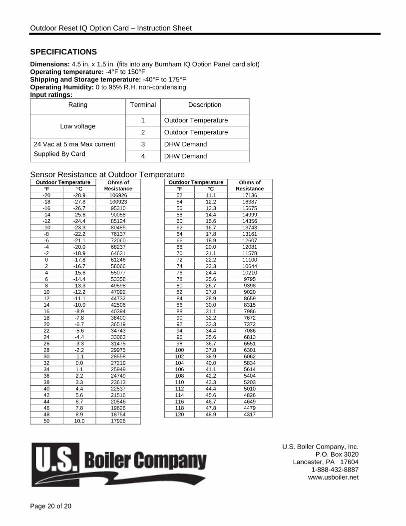
SPECIFICATIONS Dimensions: 4.5 in. x 1.5 in. (fits into any Burnham IQ Option Panel card slot) Operating temperature: -4°F to 150°F Shipping and Storage temperature: -40°F to 175°F Operating Humidity: 0 to 95% R.H. non-condensing Input ratings:
Rating Terminal Description
Low voltage 1 Outdoor Temperature
2 Outdoor Temperature
24 Vac at 5 ma Max current Supplied By Card
3 DHW Demand
4 DHW Demand Sensor Resistance at Outdoor Temperature
Outdoor Temperature Ohms of Resistance
Outdoor Temperature Ohms of Resistance °F °C °F °C
-20 -28.9 106926 52 11.1 17136 -18 -27.8 100923 54 12.2 16387 -16 -26.7 95310 56 13.3 15675 -14 -25.6 90058 58 14.4 14999 -12 -24.4 85124 60 15.6 14356 -10 -23.3 80485 62 16.7 13743 -8 -22.2 76137 64 17.8 13161 -6 -21.1 72060 66 18.9 12607 -4 -20.0 68237 68 20.0 12081 -2 -18.9 64631 70 21.1 11578 0 -17.8 61246 72 22.2 11100 2 -16.7 58066 74 23.3 10644 4 -15.6 55077 76 24.4 10210 6 -14.4 53358 78 25.6 9795 8 -13.3 49598 80 26.7 9398 10 -12.2 47092 82 27.8 9020 12 -11.1 44732 84 28.9 8659 14 -10.0 42506 86 30.0 8315 16 -8.9 40394 88 31.1 7986 18 -7.8 38400 90 32.2 7672 20 -6.7 36519 92 33.3 7372 22 -5.6 34743 94 34.4 7086 24 -4.4 33063 96 35.6 6813 26 -3.3 31475 98 36.7 6551 28 -2.2 29975 100 37.8 6301 30 -1.1 28558 102 38.9 6062 32 0.0 27219 104 40.0 5834 34 1.1 25949 106 41.1 5614 36 2.2 24749 108 42.2 5404 38 3.3 23613 110 43.3 5203 40 4.4 22537 112 44.4 5010 42 5.6 21516 114 45.6 4826 44 6.7 20546 116 46.7 4649 46 7.8 19626 118 47.8 4479 48 8.9 18754 120 48.9 4317 50 10.0 17926
U.S. Boiler Company, Inc. P.O. Box 3020
Lancaster, PA 17604 1-888-432-8887
www.usboiler.net