outline wireless phy: modulation and demodulation -...
TRANSCRIPT

Page 1
Wireless PHY: Modulation and Demodulation
Y. Richard Yang
09/6/2012
2
Outline
❒ Admin and recap ❒ Frequency domain examples ❒ Basic concepts of modulation ❒ Amplitude modulation ❒ Amplitude demodulation
❍ frequency shifting
3
Admin
❒ First assignment to be posted by this weekend
❒ Any feedback on pace and coverage
4
Recap: Fourier Series of Periodic Function
❒ A periodic function g(t) on [a, a+T] can be decomposed as:
❒ For periodic function on [0, 1]
g(t) = G[k]ej2π k
Tt
k=−∞
∞
∑
G[k]= 1T
g(t)e− j2π k
Ttdt
a
a+T∫
g(t) = G[k]e j2πk tk=−∞
∞
∑
G[k]= g(t)e− j2πk t dt0
1∫
5
Fourier Transform
❒ For those who are curious, we do not need it formally
❒ Problem: what if g(t) is not periodic ❒ Approach:
❍ Truncate g(t) beyond [-L/2, L/2] (i.e., set = 0) and then repeat to define gL(t)
gL (t) = GL[k]ej2π k
Lt
k=−∞
∞
∑ GL[k]= 1L
gL (t)e− j2π k
Ltdt
−L/2
L/2∫
6
Fourier Transform
GL[k]= 1L
gL (t)e− j2π k
Ltdt
−L/2
L/2∫ GL[k]= Δf G( fk )
gL (t) = G( fk )ej2π fk t
k=−∞
∞
∑ Δf
fk =kL G( fk ) = gL (t)e− j2π fk t dt
−∞
∞
∫Define Δf = 1L
GL[k]= 1L
gL (t)e− j2π k
Ltdt
−L/2
L/2∫
≈ G( f )e j2π ft df−∞
∞
∫
Fourier Transform
G( f ) = g(t)e− j2π f t dt−∞
∞
∫ f (t) = G( f )e j2π ft df−∞
∞
∫
Page 2
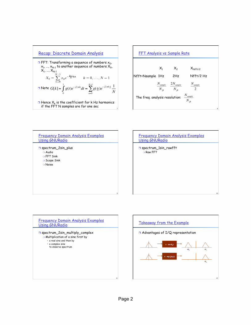
Recap: Discrete Domain Analysis
❒ FFT: Transforming a sequence of numbers x0, x1, …, xN-1 to another sequence of numbers X0, X1, …, XN-1
❒ Note
❒ Hence Xk is the coefficient for k Hz harmonics if the FFT N samples are for one sec
7
G[k]= g(t)e− j2πkt0
1
∫ dt ≈ g( nN )e− j2πk nN
n=0
N−1
∑ 1N
8
FFT Analysis vs Sample Rate
X1
Nfft=Nsample
X2 XNfft/2
1Hz 2Hz Nfft/2 Hz
Nsample
N fft
2Nsample
N fft
Nsample
2
The freq. analysis resolution:
Nsample
N fft
9
Frequency Domain Analysis Examples Using GNURadio
❒ spectrum_2sin_plus ❍ Audio ❍ FFT Sink ❍ Scope Sink ❍ Noise
10
Frequency Domain Analysis Examples Using GNURadio
❒ spectrum_1sin_rawfft ❍ Raw FFT
11
Frequency Domain Analysis Examples Using GNURadio
❒ spectrum_2sin_multiply_complex ❍ Multiplication of a sine first by
• a real sine and then by • a complex sine
to observe spectrum
12
Takeaway from the Example
❒ Advantages of I/Q representation

Page 3
13
I/Q Multiplication Also Called Quadrature Mixing
spectrum of complex signal x(t)
spectrum of complex signal x(t)ej2f0t
spectrum of complex signal x(t)e-j2f0t
14
Basic Question: Why Not Send Digital Signal in Wireless Communications?
❒ Signals at undesirable frequencies ❍ suppose digital frame repeat every T seconds,
then signal decomposes into frequencies at 1/T, 2/T, 3/T, …
❍ let T = 1 ms, generates radio waves at frequencies of 1 KHz, 2 KHz, 3 KHz, …
1
0 digital signal
t
15
Frequencies are Assigned and Regulated
Europe USA Japan
Cellular
Phones
GSM 450 - 457, 479 -
486/460 - 467,489 -
496, 890 - 915/935 -
960,
1710 - 1785/1805 -
1880
UMTS (FDD) 1920 -
1980, 2110 - 2190
UMTS (TDD) 1900 -
1920, 2020 - 2025
AMPS , TDMA , CDMA
824 - 849,
869 - 894
TDMA , CDMA , GSM
1850 - 1910,
1930 - 1990
PDC
810 - 826,
940 - 956,
1429 - 1465,
1477 - 1513
Cordless
Phones
CT1+ 885 - 887, 930 -
932
CT2
864 - 868
DECT
1880 - 1900
PACS 1850 - 1910, 1930 -
1990
PACS - UB 1910 - 1930
PHS
1895 - 1918
JCT
254 - 380
Wireless
LANs
IEEE 802.11
2400 - 2483
HIPERLAN 2
5150 - 5350, 5470 -
5725
902 - 928
I EEE 802.11
2400 - 2483
5150 - 5350, 5725 - 5825
IEEE 802.11
2471 - 2497
5150 - 5250
Others RF - Control
27, 128, 418, 433,
868
RF - Control
315, 915
RF - Control
426, 868
16
Spectrum and Bandwidth: Shannon Channel Capacity ❒ The maximum number of bits that can be
transmitted per second by a physical channel is:
where W is the frequency range of the channel,
and S/N is the signal noise ratio, assuming Gaussian noise
)1(log2 NSW +
17
Frequencies for Communications
VLF = Very Low Frequency UHF = Ultra High Frequency LF = Low Frequency SHF = Super High Frequency MF = Medium Frequency EHF = Extra High Frequency HF = High Frequency UV = Ultraviolet Light VHF = Very High Frequency
Frequency and wave length: λ = c/f
wave length λ, speed of light c ≅ 3x10⁸m/s, frequency f
1 Mm 300 Hz
10 km 30 kHz
100 m 3 MHz
1 m 300 MHz
10 mm 30 GHz
100 µm 3 THz
1 µm 300 THz
visible light VLF LF MF HF VHF UHF SHF EHF infrared UV
optical transmission coax cable twisted pair
18
Why Not Send Digital Signal in Wireless Communications?
voice
Transmitter
20-20KHz
Antenna: size ~ wavelength
At 3 KHz, λ =cf
=3×10⁸
3×103=100km
Antenna too large! Use modulation to transfer
to higher frequency

Page 4
19
Outline
❒ Recap ❒ Frequency domain examples ❒ Basic concepts of modulation
20
❒ The information source ❍ Typically a low frequency signal ❍ Referred to as baseband signal
q Carrier q A higher frequency sinusoid q Example cos(2π10000t)
q Modulated signal q Some parameter of the carrier (amplitude, frequency, phase)
is varied in accordance with the baseband signal
Basic Concepts of Modulation Basic Concept of Modulation
The information source Typically a low frequency signal Referred to as the “baseband signal”
Carrier A higher frequency sinusoid Example: cos(2π10000t)
Modulated Signal Some parameter of the carrier (amplitude, frequency, phase) is varied in
accordance with the baseband signal
x(t)
t
X(f)
f
Modulator baseband
carrier Modulated signal
7/8/10 5 Flynn/Katz
Basic Concept of Modulation
The information source Typically a low frequency signal Referred to as the “baseband signal”
Carrier A higher frequency sinusoid Example: cos(2π10000t)
Modulated Signal Some parameter of the carrier (amplitude, frequency, phase) is varied in
accordance with the baseband signal
x(t)
t
X(f)
f
Modulator baseband
carrier Modulated signal
7/8/10 5 Flynn/Katz
21
Types of Modulation
❒ Analog modulation ❍ Amplitude modulation (AM) ❍ Frequency modulation (FM) ❍ Double and signal sideband: DSB, SSB
❒ Digital modulation ❍ Amplitude shift keying (ASK) ❍ Frequency shift keying: FSK ❍ Phase shift keying: BPSK, QPSK, MSK ❍ Quadrature amplitude modulation (QAM)
22
Outline
❒ Recap ❒ Frequency domain examples ❒ Basic concepts of modulation ❒ Amplitude modulation
Amplitude Modulation (AM) Block Diagram
Time Domain
Frequency Domain
m x +
Ac cos �ct
x(t) xAM(t)=Ac [1+mx(t)]cos �ct
X(f)
f -fm fm
XAM(f)
f -fc fc
Signal information is contained in the sidebands
7/8/10 7 Flynn/Katz 23
Example: Amplitude Modulation (AM)
❒ Block diagram
❒ Time domain
❒ Frequency domain
Amplitude Modulation (AM) Block Diagram
Time Domain
Frequency Domain
m x +
Ac cos �ct
x(t) xAM(t)=Ac [1+mx(t)]cos �ct
X(f)
f -fm fm
XAM(f)
f -fc fc
Signal information is contained in the sidebands
7/8/10 7 Flynn/Katz
Amplitude Modulation (AM) Block Diagram
Time Domain
Frequency Domain
m x +
Ac cos �ct
x(t) xAM(t)=Ac [1+mx(t)]cos �ct
X(f)
f -fm fm
XAM(f)
f -fc fc
Signal information is contained in the sidebands
7/8/10 7 Flynn/Katz
Amplitude Modulation (AM) Block Diagram
Time Domain
Frequency Domain
m x +
Ac cos �ct
x(t) xAM(t)=Ac [1+mx(t)]cos �ct
X(f)
f -fm fm
XAM(f)
f -fc fc
Signal information is contained in the sidebands
7/8/10 7 Flynn/Katz
Amplitude Modulation (AM) Block Diagram
Time Domain
Frequency Domain
m x +
Ac cos �ct
x(t) xAM(t)=Ac [1+mx(t)]cos �ct
X(f)
f -fm fm
XAM(f)
f -fc fc
Signal information is contained in the sidebands
7/8/10 7 Flynn/Katz 24
Example: am_modulation Example
❒ Setting ❍ Audio source (sample 32K) ❍ Signal source (300K, sample 800K) ❍ Multiply
❒ Two Scopes
❒ FFT Sink

Page 5
25
Example AM Frequency Domain
Note: There is always the negative freq. in the freq. domain. 26
Problem: How to Demodulate AM Signal?
Amplitude Modulation (AM) Block Diagram
Time Domain
Frequency Domain
m x +
Ac cos �ct
x(t) xAM(t)=Ac [1+mx(t)]cos �ct
X(f)
f -fm fm
XAM(f)
f -fc fc
Signal information is contained in the sidebands
7/8/10 7 Flynn/Katz
Amplitude Modulation (AM) Block Diagram
Time Domain
Frequency Domain
m x +
Ac cos �ct
x(t) xAM(t)=Ac [1+mx(t)]cos �ct
X(f)
f -fm fm
XAM(f)
f -fc fc
Signal information is contained in the sidebands
7/8/10 7 Flynn/Katz
27
Outline
❒ Recap ❒ Frequency domain examples ❒ Basic concepts of modulation ❒ Amplitude modulation ❒ Amplitude demodulation
❍
28
Outline
❒ Admin and recap ❒ Frequency domain examples ❒ Basic concepts of modulation ❒ Amplitude modulation ❒ Amplitude demodulation
❍ frequency shifting
29
Design Option 1
❒ Step 1: Multiply signal by e-jfct
❍ Implication: Need to do complex multiple multiplication
30
Design Option 1 (After Step 1)
-2fc

Page 6
31
Design Option 1 (Step 2)
❒ Apply a Low Pass Filter to remove the extra frequencies at -2fc
-2fc
32
Design Option 1 (Step 1 Analysis)
❒ How many complex multiplications do we need for Step 1 (Multiply by e-jfct)?
33
Design Option 2: Quadrature Sampling
34
Quadrature Sampling: Upper Path (cos)
35
Quadrature Sampling: Upper Path (cos)
36
Quadrature Sampling: Upper Path (cos)

Page 7
37
Quadrature Sampling: Lower Path (sin)
38
Quadrature Sampling: Lower Path (sin)
39
Quadrature Sampling: Lower Path (sin)
40
Quarature Sampling: Putting Together
41
Exercise: SpyWork
❒ Setting: a scanner scans 128KHz blocks of AM radio and saves each block to a file (see am_rcv.py).
❒ SpyWork: Scan the block in a saved file to find radio stations and tune to each station (each AM station has 10 KHz)