outokumpu sx ew technology package raimo …outokumpu technology oy, metals processing,...
TRANSCRIPT

The South African Institute of Mining and Metallurgy The Third Southern African Conference on Base Metals Raimo Kuusisto, Pertti Pekkala and George J. Karcas
Page 321
OUTOKUMPU SX EW TECHNOLOGY PACKAGE
Raimo Kuusisto Outokumpu Technology Oy, Metals Processing, Hydrometallurgy
Pertti Pekkala
Outokumpu Technology Oy, Metals Processing, Hydrometallurgy
George J. Karcas Outokumpu Technology Oy, Metals Processing, Hydrometallurgy
ABSTRACT
Ongoing Outokumpu development in Solvent Extraction and Electrowinning Technology, involving all aspects of process chemistry, equipment and control, extends over a period of close to 30 years. The development in SX started with molybdenum and rhenium, continued with zinc, manganese, cobalt and nickel and is now focusing on copper. The OutoCompact VSF™ SX concept, which has been recently introduced, is a honed version of earlier VSF™ technology. The Outokumpu VSF™ ("Vertical Smooth Flow") SX package includes the DOP ("Dispersion Overflow Pump") units, the Spirok Mixers, the OutoCompact Settlers including their DDG ("Dispersion Depletor Gate") fences and tank farm equipment such as the LOS ("Loaded Organic Scrubbing") tank as well as the CEP ("Copper Electrolyte Purifying") tank. Although the VSF™ SX package can be implemented according to several optional lay-outs, the so-called Track version has lately been introduced to the advantage of new plants. The new OutoCompact SX technology decreases the footprint of future VSF™ plants. The lay-out, including plant size flexibility, have further been improved by Outokumpu’s new OutoReverse settler technology. Two of several SX plants currently under construction rely on reverse settlers in order to maximize their performance. The Outokumpu EW technology includes process know-how as well as proprietary equipment. The copper EW package consists of permanent stainless steel cathodes based on wax-less technology and lead anodes utilising polymer concrete cells with the double contact bus bar system and ventilation hoods fitted for efficient mist control. The lifting of cell hoods, as well as cathode washing, is done by the cathode pulling crane. Proper electrolyte flows and matching current density further ensure high productivity of LME grade copper cathodes.

The South African Institute of Mining and Metallurgy The Third Southern African Conference on Base Metals Raimo Kuusisto, Pertti Pekkala and George J. Karcas
Page 322
INTRODUCTION
The Outokumpu Technology Solvent Extraction and Electrowinning packages combine Basic Engineering, Integrated Proprietary Equipment, and Supervision Services with Process Guarantees, as well as the possibility of Copper Off Take Agreements.
Outokumpu’s proven track record in SX EW, offering technically advanced equipment, which renders optimal operation at all stages of the process, gives the operator the ability to maximize the benefits while minimizing operational costs.
VERTICAL SMOOTH FLOW TECHNOLOGY The Vertical Smooth Flow (VSF) Solvent Extraction Technology Package is predominant in North and South America, accounting for over 25% of the world’s Copper SX capacity. New applications are being commissioned in Laos and Mexico during the 2005 calendar year. Solvent Extraction is a frequently used unit process in Outokumpu hydrometallurgical operations. Twelve out of nineteen SX processes in our reference list (1) are or have been in use in Finland. A constant pursuit of better SX performance has resulted in an uninterrupted development work covering all aspects of the SX processes. In the early 90’s the accumulated SX know-how had already passed a level, after which the keystone ideas of uniform mixing and low shear pumping could be realized. The first SX processes to use mixer-settlers relying on, what is nowadays known as Spirok mixing and DOP pumping, were a cobalt/magnesium circuit and a nickel circuit. Since that time, four more VSF SX plants have been built in Finland including one large plant for cobalt recovery and a very compact one for copper. Simultaneously with the SX progress in Finland, the VSF concept was introduced for large copper SX plants like Zaldívar and Radomiro Tomic in Chile and Morenci in USA. This development has now resulted in the OutoCompact Copper SX focusing on economical key items impacting on stable copper cathode production, efficient space utilization and top-level operational performance. A glimpse of how our cobalt and copper SX developments interrelate with each other can be obtained from Figure 1 showing a typical OutoCompact cobalt mixer-settler and its counterpart for copper, shown in Figure 2.
Figure 1 - OutoCompact Cobalt Mixer-Settler

The South African Institute of Mining and Metallurgy The Third Southern African Conference on Base Metals Raimo Kuusisto, Pertti Pekkala and George J. Karcas
Page 323
Figure 2 - OutoCompact Copper Mixer-Settler VSF Technology separates the pumping and mixing functions by executing them in separate units. This allows the operator to simultaneously maintain optimum conditions for mixing and pumping ensuring that the process is not compromised. The mixing intensity is kept at the optimum level and pumping is controlled to achieve low head conditions, which together with horizontal pipe runs minimises high shear forces, restrains organic phase oxidation, and ensures low operating costs and flexibility in achieving the maximum allowable flow rate of the pregnant leach solution. The 3D - “Deep Dense Dispersion” settler design, coupled with the VSF pumping and mixing technology results in high specific settler throughput with low organic entrainment. VSF operators have reported the mean annual O/A entrainments in the Raffinate and Rich Electrolyte of typically being less than 15 ppm. Outokumpu’s proprietary DDG - “Dispersion Depletor Gate” picket fence design ensures that a thick and dense dispersion layer is predominant in the front end of the settler. This dispersion band allows for the filtration of small droplets, hence, ensuring low entrainment values. Due to the settler and picket fence design, the dispersion cannot spread to the discharge end of the settler, hence allowing for good flow capacity flexibility.
It is interesting to note that both Spirok mixers and the DOP unit are in-built in the settler tank in an OutoCompact cobalt mixer-settler. The compactness and its benefits become obvious by considering the present specific settling rate in the settler, ranging between 8 - 14 m3/h/m2. Due to the location of the DOP, the mixers are on the same side of the line of

The South African Institute of Mining and Metallurgy The Third Southern African Conference on Base Metals Raimo Kuusisto, Pertti Pekkala and George J. Karcas
Page 324
mixer-settlers. This gives a process designer additional freedom to create advantageous layout alternatives, similar to those of plants using reverse flow mixer-settlers. In large copper SX plants the DOP units and the mixer tanks have to be built outside the settler basin for size constraint reasons. A large copper SX plant treating a total solution flow close to 5000 m3/h is relying on a DOP unit with a diameter of about 6000 mm, whereas a relatively large cobalt SX plant seldom even requires a DOP close to 2000 mm. A common feature of both copper and cobalt SX plants is the compact settler design using intensified phase separation. A combination of proper settler depth, a guiding inlet fence, and sets of “Dispersion Depletor Gates” (DDGs) have proved to be very successful compacting tools. The thickness and the level of the dispersion bands are predetermined by the settler design itself. Of course the dispersion bands are only fully developed provided the plant flows exceed prerequisite flows. The Outokumpu SX Technology Package also features a loaded organic (LO) tank design with proprietary scrub solution circulation and coalescing fences. The Outokumpu layout configuration places the LO tank, which also requires less excavation work than conventional designs, in the center area of the SX plant in order to minimize organic inventory. The transfer of impurities to the electrolyte circuit is minimized with the VSF Technology due to:
Separate pumping and mixing, which prevent the formation of extra fine droplets. Capturing of occasional high Rich Electrolyte O/A entrainments, caused, for
example through operator error, by the Rich Electrolyte After Settler. Efficient washing of any remaining aqueous entrainment with a combination
washing mixer-settler and a scrubber type LO-tank. The VSF mixer settlers are also efficient coalescers, actually performing better than commercial coalescers, hence, eliminating the need for additional coalescers.
Figure 3 – Outokumpu VSF Solvent Extraction Plant

The South African Institute of Mining and Metallurgy The Third Southern African Conference on Base Metals Raimo Kuusisto, Pertti Pekkala and George J. Karcas
Page 325
VSF SOLVENT EXTRACTION PROPRIETARY EQUIPMENT The main equipment that the Outokumpu VSF Technology package consists of, are the Dispersion Overflow Pump (DOP), the SPIROK mixer, and the Outocompact settler. DOP Pumping Unit The main advantage of the VSF technology is that it separates pumping and mixing in order to ensure low entrainment losses because it is possible to constantly control and maintain the mixing intensity at the optimum level, regardless of whether the PLS flow rate has to rise above the design value or is not stable.
The DOP unit “Dispersion Overflow Pump” consists of a suction cylinder with a conical overflow rim, a turbine, a flow stabilizer and a baffled cylindrical outer tank (Figure 4).
Figure 4 – Dispersion Overflow Pump (DOP) Unit
The DOP’s operating philosophy is based on utilising a relatively large slow speed turbine, and on minimizing pressure losses in the VSF system, with for example, the use of horizontal settler outlets. The first mixing contact between the aqueous and the organic solutions occurs in the turbine casing, where the chemical mass-transfer reactions start immediately and vigorously. A typical retention time in the turbine casing is 3-5 seconds, whereas in the outer tank it is close to half a minute. The mixing intensity in the outer tank matches that of the main mixers hence allowing optimal mixing. Thanks to this very short retention time in the turbine casing, and a low tip speed, the crud formation in the VSF units can be kept astonishingly low, especially when treating PLS which contains high iron.
Flow Stabilizer
Turbine
Conical Overflow
Rim
Suction Cylinder

The South African Institute of Mining and Metallurgy The Third Southern African Conference on Base Metals Raimo Kuusisto, Pertti Pekkala and George J. Karcas
Page 326
SPIROK Mixing Unit The Spirok mixers are designed to provide gentle and uniform mixing at a rate that results in proper dispersion formation giving the appropriate mass transfer rate. Low shear mixing in combination with an organic continuous dispersion mode that contains a high hold-up of aqueous drops (O/A 0.7-0.9), has proven to be a very efficient way of improving the entrainment and crud situation. The VSF mixing unit (Figure 5) consists of two cylindrical baffled mixer tanks equipped with double helical Spirok stirrers and an uptake channel, the latter connecting the last mixer tank with the settler. The dip cover structure of the mixer tank prevents air from entering into the dispersion.
Figure 5 – Vertical Smooth Flow (VSF) Mixing Unit
OutoCompact Settling Unit Settler design is a critical factor in solvent extraction plant operation. The OutoCompact settler is based on the concept of having a deep, dense and thick dispersion layer at the feed side of the settler. The incoming dispersion flow is distributed evenly with the flow distributor and one non-jetting picket fence. The dispersion is then kept in a compressed state with three DDG fences. The dense dispersion layer filtrates small droplets and enhances coalescence, ensuring low entrainment values. It is important to note that more flexibility to handle higher feed flow rates is achieved when the dispersion is not allowed to spread over the whole settling area. Separated organic and aqueous solutions are finally collected into
Cylindrical Mixing Tank
Cover
Spirok Stirrer
Uptake Channel

The South African Institute of Mining and Metallurgy The Third Southern African Conference on Base Metals Raimo Kuusisto, Pertti Pekkala and George J. Karcas
Page 327
launders. The aqueous inner circulation is taken from the settler bulk. The settler design is presented in figures 6, 7, and 8.
Figure 6 – VSF mixer settler
Figure 7 - OutoCompact Copper Mixer-Settler Picket Fence and Dispersion Profile
11- 5-1999 10:04:34 / Tulostaja: lyyraju

The South African Institute of Mining and Metallurgy The Third Southern African Conference on Base Metals Raimo Kuusisto, Pertti Pekkala and George J. Karcas
Page 328
Figure 8 - OutoCompact Copper Mixer-Settler Picket Fence Design
Outokumpu Electrowinning Technology Outokumpu’s electrowinning technology is based on its own stainless steel permanent cathode production concept, utilizing widely utilized and proven proprietary tankhouse equipment. The Outokumpu electrowinning process, in its entirety, utilizes cell size up to 84 cathodes per cell, allowing for more operating efficiency and reduced tankhouse foot print area. The first plant utilizing this concept was started up in 2001 at OMG Kokkola Chemicals in Finland. New plants to be commissioned are in Laos, Mexico and Russia The Outokumpu electrowinning technology package includes the following proprietary design equipment:
Full Deposit Stripping Machine with wide range of manual or automated options Stainless Steel Permanent Cathodes Lead - Anodes Double Contact Bus Bar System Crane and Bale with integrated electrode washing system Polymer concrete electrolytic cells with up to 84 cathodes per cell Acid Mist Capture System
A brief description of the Outokumpu tankhouse technology package equipment follows

The South African Institute of Mining and Metallurgy The Third Southern African Conference on Base Metals Raimo Kuusisto, Pertti Pekkala and George J. Karcas
Page 329
Figure 9 – Outokumpu Electrowinning Plant
Full Deposit Stripping Machine
Outokumpu’s full deposit stripping machine features either non flex or flex stripping. The non flexing approach is applicable in conjunction with Outokumpu’s Acid Mist Capture System, or any other system that does not utilise de-mister balls, while the flexing approach can be applied in all cases. This is due to the fact that de-mister balls result in a rounded copper deposit at the top of the cathode, making it difficult for a knife to make the initial penetration. Outokumpu’s proprietary flexing method, in comparison with previous methods, extends the life of both stainless steel blanks and edge strips by executing the flex very gently and by minimising the flexing distance. The Outokumpu full deposit stripping machine can produce either separate cathodes or TACO cathodes, which are connected at the bottom. In either case, it is done without waxing the bottom of the blanks and with only side edge strips. The capacity of the Outokumpu full deposit stripping machine can be customised according to the requirements of the operation. and it can be on a manual, semi- automatic or fully automatic basis.

The South African Institute of Mining and Metallurgy The Third Southern African Conference on Base Metals Raimo Kuusisto, Pertti Pekkala and George J. Karcas
Page 330
Additional benefits of mechanised stripping are that the Outokumpu full deposit stripping machine can physically sort higher and lower quality deposits into separate stacks without requiring manual intervention. It can also execute automatic or manual sampling, corrugating, weighing, marking, labelling, and strapping.
Figure 10 – Outokumpu Full Deposit Stripping Machine
Stainless Steel Permanent Cathodes The Outokumpu permanent cathode is made of AISI 316L stainless steel and has a plating area of approximately 1.0 m2 per side. The hanger bar is constructed by metallurgically joining a large solid copper cross section into a stainless steel tube. Only the tips of the hanger bar expose the copper at the position where contact will be made with the copper bus bar. The stainless steel tube is laser welded to the plate. This construction results in low electrical losses throughout the entire life of the cathode with high mechanical strength, hence no bending over time, high dimensional accuracy and virtually no deterioration of the copper cross section over time. Furthermore, as there are only stainless to stainless welds between the bar and the plate, there is a high resistance against corrosion, even when the electrodes are below the ventilation hoods. A very important advantage of Outokumpu permanent cathodes is that the hanger bar can be removed and utilized on a new plate in the case of damage to the plate, or replacement at the end of the plate’s useful life.
The South African Institute of Mining and Metallurgy The Third Southern African Conference on Base Metals Raimo Kuusisto, Pertti Pekkala and George J. Karcas
Page 331
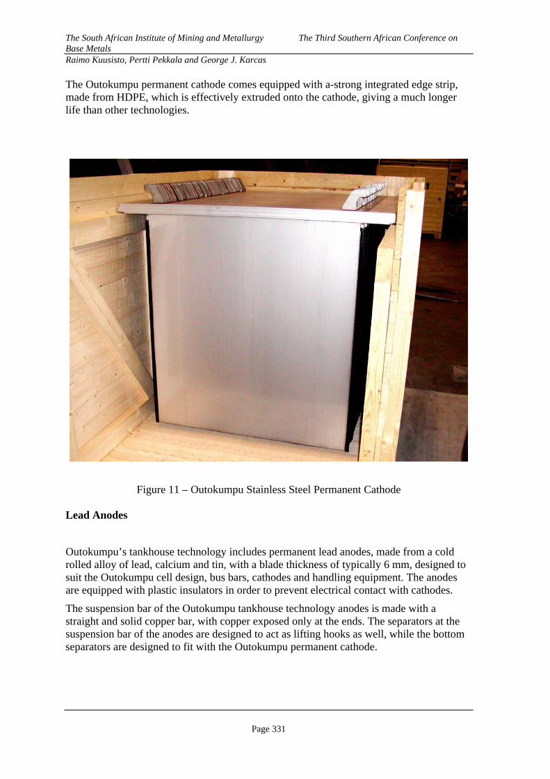
The Outokumpu permanent cathode comes equipped with a-strong integrated edge strip, made from HDPE, which is effectively extruded onto the cathode, giving a much longer life than other technologies.
Figure 11 – Outokumpu Stainless Steel Permanent Cathode Lead Anodes
Outokumpu’s tankhouse technology includes permanent lead anodes, made from a cold rolled alloy of lead, calcium and tin, with a blade thickness of typically 6 mm, designed to suit the Outokumpu cell design, bus bars, cathodes and handling equipment. The anodes are equipped with plastic insulators in order to prevent electrical contact with cathodes.
The suspension bar of the Outokumpu tankhouse technology anodes is made with a straight and solid copper bar, with copper exposed only at the ends. The separators at the suspension bar of the anodes are designed to act as lifting hooks as well, while the bottom separators are designed to fit with the Outokumpu permanent cathode.

The South African Institute of Mining and Metallurgy The Third Southern African Conference on Base Metals Raimo Kuusisto, Pertti Pekkala and George J. Karcas
Page 332
Figure 12 – Outokumpu EW Process Lead Anode
Double Contact Busbar System
Outokumpu Technology has developed the Double Contact Bus Bar System, which effectively makes bus bar contact with both sides of each anode and cathode. This is done with the use of an equaliser bar on each side for each electrode, which effectively picks up any stray current from the hanger bar and distributes it to all electrodes over the entire cell length. The Outokumpu Double Contact Inter-cell Bus bar Assembly consists of one main inter-cell bus bar, two equalizing bus bars, one main insulator, and one auxiliary insulator. The bus bars are made of oxygen free copper and all insulators of high quality Fiberglas reinforced vinyl ester resin, specially designed for electrical purposes. The Outokumpu double contact bus bar system results in even current distribution throughout the cell length, less short circuits, longer permanent anode life, and better cathode quality, having less lead and sulphur, even weight distribution, and above all, lower electrical energy consumption.

The South African Institute of Mining and Metallurgy The Third Southern African Conference on Base Metals Raimo Kuusisto, Pertti Pekkala and George J. Karcas
Page 333
Figure 13 – Outokumpu Double Contact Bus Bar System
Tankhouse Crane and Bale
The Outokumpu electrowinning plant’s material handling system can either be based on a fully automatic crane and bale, or a manual crane and bale, extracting every second cathode at a time. The electrode bale has mechanical aligning combs, mounted on both sides on the bottom part of the guide frame in order to ensure that the cathodes do not hit each other during crane movements and that they are safely inserted between anodes when placed into cells. The system is provided with a washing system (tank – pump – piping – nozzles), which enables excellent and constant chemical quality of produced copper cathodes. The crane is a heavy-duty industrial overhead bridge crane designed specifically for the conditions of the tankhouse

The South African Institute of Mining and Metallurgy The Third Southern African Conference on Base Metals Raimo Kuusisto, Pertti Pekkala and George J. Karcas
Page 334
Figure 14 – Outokumpu Tankhouse Crane and Bale
Electrowinning Cells
The electrowinning cells are made of polymer concrete and are equipped with an electrolyte inlet manifold and an overflow box, holes for crane bale positioning, and an acid mist capture system integrated into the cell body. These electrolytic cells are specially designed for the copper electrowinning process. The benefits of polymer concrete cells are well known, from simple and easy installation and lower maintenance costs.
The Outokumpu electrowinning plant assumes typically an 84 cathode cell, which ensures efficient materials and hood handling and smaller tankhouse foot print. The technology can also be applied to systems with smaller cells.
Acid Mist Capture System In order to capture all evolving harmful emissions from electrolytic cells, such as - sulphuric acid mist, Outokumpu has developed its Acid Mist Capture System where the cells are covered with acid mist collection hoods and the off-gases are transferred into a wet-scrubber system that removes practically all acid from the evolving gases. The recovered acid is returned back into the process.

The South African Institute of Mining and Metallurgy The Third Southern African Conference on Base Metals Raimo Kuusisto, Pertti Pekkala and George J. Karcas
Page 335
This reduces the risk of corrosion, both inside and outside the tankhouse, and the capacity and the cost of the general ventilation system can be considerably less when compared to conventional systems. This system eliminates the need for balls or foam on the surface of the electrolyte, simplifying drastically the everyday plant operation. Sulphuric acid consumption is minimized as it can be recycled. No gas masks are required in the cell aisle and health and safety requirements are fulfilled in all countries throughout the world.
Figure 15 – Outokumpu Acid Mist capture System

The South African Institute of Mining and Metallurgy The Third Southern African Conference on Base Metals Raimo Kuusisto, Pertti Pekkala and George J. Karcas
Page 336
Figure 16 – Outokumpu Tankhouse Technology Package Conclusion Outokumpu’s Solvent Extraction Technology provides the operator with the ability to maximise the output of the plant while minimising organic entrainments and losses. The ability to control, and optimise, pumping and mixing separately renders the operation to perform effectively and efficient. Outokumpu’s experience in cathode stripping has gained it the respect of its peers. With flexing that minimises the impact, it can extend the life of the stainless steel blank and edge strip, thereby minimising operating costs and maximising throughput. Outokumpu’s permanent cathodes allow for easier and more effective operation of the tankhouse. Minimum voltage losses, enhanced by the double contact bus bar system ensures that current is evenly distributed along the cell without stray currents, resulting in a uniform cathode weight across the cell. The above factors all ensure maximum current efficiency and minimum energy consumption. Finally, Outokumpu’s acid mist capture system effectively renders the electrowinning environment free of acid mist.
Transformer-Rectifier to convert AC to DC current
Crane and Bale
Off-gas Scrubbers and fans for acid mist capture
Basic and Detailed Engineering, Installation-, Start-up Supervision and Training
Full Deposit Stripping Machine
Electrolytic Cells with Hoods including:
Electrodes: - Permanent Cathodes - Lead anodes
Busbar System for DC current
Pumps, Tanks, Piping, Ducting and Field Instruments