over-center tm hydraulic aluminum lift - boat lifts, pwc ... · 5 1 2 3 4 5 6 mechanism parts list...
TRANSCRIPT
READ complete manual CAREFULLYBEFORE attempting assembly or operation
08/15
L392-0073, REV C1
tmOver-Center Hydraulic Aluminum Lift
6,000 lbs Capacity Models 6k51 &6k62
866-GO-BASTA
www.gobasta.com
ASSEMBLYINSTALLATIONREPLACEMENT PARTS
Copyright 2015 Basta Marine©Basta Marine, Inc. Bellevue WA 98005 USA
6k51/6k62
Assembly Instructions .........................................................................Pages 6 - 18
First Use / Adjustments
..……………...........................................................Page 18
Basta Marine Boat Lift Accessories ....…………………... ...….….….Page 24 ......
Parts List and Diagrams .............................................................Pages 4, 5, 15, 20
2
INDEX
Warning......………………..............................................................................Page 2, 3
Warranty .............................…...........................................................................Page 23
NOTE:Your boat lift is a very heavy piece of equipment. Improper use could result in serious injury or death. For the safety of people and property please review the safety guidelines below for your new boat lift.
Do not exceed the maximum weight capacity specified for the lift. SEE PAGE 18.
Passengers should stand clear of the lift and not be aboard when the lift is in operation.
Do not play on or near the lift.
Leave your automatic bilge pump turned on the automatic setting to prevent the accumulation of rain water.
Service your lift regularly.
Do not service the unit with the boat on the lift.
Use a mooring line for additional security.
Only use Basta Marine approved oil in lift. Special biodegradable non-toxic hydraulic fluid
Visually inspect all parts and assemblies for defects and damage prior to assembling the lift.
Do not install the lift alone.
Install the lift on firm and level ground.
Verify the lower frame of the lift is level before each use.
Turn the power off during periods of non-use.
This hoist is a heavy piece of equipment please use with care.
The lift should not be used for any other purpose besides the lifting of boats & watercraft.
WARNING
part # Y354-0001
Manufactured under one or more of the following patents: #4895479, #4900187, #5143182, #5184914, #5311970,#6318929, #6602022, #6837651, #7021861, #7210420,
#7712425, #D503692 Canada #2089044Other patents pending
P A T E N T E D D E S I G N
Maintenance ......................…...........................................................................Page 22
Troubleshooting / FAQ .…...........................................................................Page 21
3
In the following pages various symbols are used:
indicates an illustration for a procedure.
indicates a major part described in the parts list on pages 4 and 5.
or indicate hardware items shown above and described in the parts list
on pages 4 and 5.
1&223
AA
1
After the lift is assembled and installed, all fasteners should be checked for proper tightness
and reinspected periodically.
INSPECTthe lift monthly
for frayed hoses, loosefasteners and corrosion
Before Using:
Read this manualcompletely!
!!!
lift unattended
OIL INJECTED INTO THE SKIN FROM HIGH PRESSURE
LEAKS IN HYDRAULIC SYSTEMS CAN CAUSE SEVERE
INJURY. MOST DAMAGE OCCURS DURING THE FIRST
FEW HOURS. SEEK MEDICAL ATTENTION IMMEDIATELY.
SURGICAL REMOVAL OF OIL MAY BE NECESSARY.
USE ONLY BASTA APPROVED BIODEGRADABLE HYDRAULIC FLUID
Do not exceed the maximum weight capacity specified for the lift.
6,000 LBSDANGER
MAXIMUM CAPACITY

5
1
2
3
4
5
6
MECHANISM PARTS LISTSEE PAGES 15 & 20 FOR ELECTRICAL AND HYDRAULIC PARTS
ITEM
ITEM
PART NO.
PART NO.
DESCRIPTION
DESCRIPTION
QTY.
QTY.
JJ
KK
HH
W107-0004
K204-0072
A427-0005
Stop Block, Left
Bunk Rail
Bunk Carrier Assy
1
2
4
LL W410-0039 Carpeted Bunk Board, Blue 2
MM
NN
PP
RR
SS
TT
UU
--
N/A
M621-1002
K200-0072
W107-0005
W119-0005
W119-0006
K202-0231
W111-0015
M621-1003
Base Pivot Bushing
Pivot Block
Stop Block,Right
Base Brace, Left
Base Brace, Right
H-Frame arm, inner
Base Crossmember, Aft
Bunk Pivot Bushing (part of HH)
8
4
1
1
1
1
4
1
(8)
ITEM PART NO. DESCRIPTION QTY.
1
AA
2
BB
3
CC
4
DD
5
EE
FF
GG
6
7
8
9
10
11
12
13
S362-0008
K200-0001
S313-0008
W117-0001
S313-0007
W105-0008
S322-0007
W111-0014
S342-0007
A431-0020
A431-0019
SEE PG. 20
S503-0013
S103-0517
S503-0012
S314-0032
S103-0516
S522-0801
W119-0002
Y356-0003
nut, 3/8-16 nylock SS
Leg
washer, flat 3/8 SS
Foot Pad
washer, flat 5/16 SS
Side Rail
washer, lock 5/16 SS
Base Crossmember, Fwd
nut, 5/16-18 SS
H-frame, Forward
H-frame, Aft
Hydraulic Cylinder
clevis pin, 3/4 x 3.5 SS
bolt, hex head 3/8-16 x 4.0 SS
base pivot pin SS
washer, flat 3/4 nylon
bolt, hex head 3/8-16 x 3.75 SS
ring cotter pin .091 x 3/4 SS
bunk bolt weldment SS
anti-seize grease packet
26
4
40
4
6
2
6
1
6
1
1
1
2
2
4
2
20
2
4
1
S532-1801 P pin, SS 414
S503-0010 bunk pin, SS 415
S362-0110 nut,1/2-13 nylock thin SS 816
17
S313-0010 washer, flat 1/2 SS 818
F730-0004 plastic cap for 2-3/8" OD sq tube 419
20
21
22
23
S103-0705
S503-0011
S103-0338
S322-0006
S520-1706
bolt, hex head 1/4-20 x 1.75 full thread SS
bolt, hex head 1/2-13 x 1.0 SS
extension arm pin [6k62 only]
washer, lock 1/4 SS
cotter pin 3/16 x 2.0 SS
4
[4]
4 [8]
4 [8]
4
ITEM PART NO. DESCRIPTION QTY.
11
19
5
4
3
12
22
14
8
10
13
16
18
17
6
9
2
2
1
15
21
20
7
2
2
1
10
1
2
23
21
20
[6k62 only]
20&21
15
20&21
15
9
6
11
MMEE
14
14
14
14
DD
TT
1919
1919
22
22
22
22
10&2
10&210&2
10&2
1&21&2
1&2
1&2
BBBB
BBBB
BBBB
BBBB
AA
AA
AA
AA
CC
CC
1&2 1&2
10&2
10&2
6
11
MM
10&2
10&21&2
7&2
7&21&2
LL
KK 12
12
3 4&5
3 4&5
3 4&5
16&18
16&18
16&1816&18
HH
HH
20&21
15
20&21
15
GG
JJ
PP
1&2
NN
FF
20&21
23
UU
20&21
23
UU
6k61 only6k61 only
NN1&2
10
108
8
17
RR
SS
1&2
NN1&2
7&21&2
1&2
10&2
4

5
1
2
3
4
5
6
MECHANISM PARTS LISTSEE PAGES 15 & 20 FOR ELECTRICAL AND HYDRAULIC PARTS
ITEM
ITEM
PART NO.
PART NO.
DESCRIPTION
DESCRIPTION
QTY.
QTY.
JJ
KK
HH
W107-0004
K204-0072
A427-0005
Stop Block, Left
Bunk Rail
Bunk Carrier Assy
1
2
4
LL W410-0039 Carpeted Bunk Board, Blue 2
MM
NN
PP
RR
SS
TT
UU
--
N/A
M621-1002
K200-0072
W107-0005
W119-0005
W119-0006
K202-0231
W111-0015
M621-1003
Base Pivot Bushing
Pivot Block
Stop Block,Right
Base Brace, Left
Base Brace, Right
H-Frame arm, inner
Base Crossmember, Aft
Bunk Pivot Bushing (part of HH)
8
4
1
1
1
1
4
1
(8)
ITEM PART NO. DESCRIPTION QTY.
1
AA
2
BB
3
CC
4
DD
5
EE
FF
GG
6
7
8
9
10
11
12
13
S362-0008
K200-0001
S313-0008
W117-0001
S313-0007
W105-0008
S322-0007
W111-0014
S342-0007
A431-0020
A431-0019
SEE PG. 20
S503-0013
S103-0517
S503-0012
S314-0032
S103-0516
S522-0801
W119-0002
Y356-0003
nut, 3/8-16 nylock SS
Leg
washer, flat 3/8 SS
Foot Pad
washer, flat 5/16 SS
Side Rail
washer, lock 5/16 SS
Base Crossmember, Fwd
nut, 5/16-18 SS
H-frame, Forward
H-frame, Aft
Hydraulic Cylinder
clevis pin, 3/4 x 3.5 SS
bolt, hex head 3/8-16 x 4.0 SS
base pivot pin SS
washer, flat 3/4 nylon
bolt, hex head 3/8-16 x 3.75 SS
ring cotter pin .091 x 3/4 SS
bunk bolt weldment SS
anti-seize grease packet
26
4
40
4
6
2
6
1
6
1
1
1
2
2
4
2
20
2
4
1
S532-1801 P pin, SS 414
S503-0010 bunk pin, SS 415
S362-0110 nut,1/2-13 nylock thin SS 816
17
S313-0010 washer, flat 1/2 SS 818
F730-0004 plastic cap for 2-3/8" OD sq tube 419
20
21
22
23
S103-0705
S503-0011
S103-0338
S322-0006
S520-1706
bolt, hex head 1/4-20 x 1.75 full thread SS
bolt, hex head 1/2-13 x 1.0 SS
extension arm pin [6k62 only]
washer, lock 1/4 SS
cotter pin 3/16 x 2.0 SS
4
[4]
4 [8]
4 [8]
4
ITEM PART NO. DESCRIPTION QTY.
11
19
5
4
3
12
22
14
8
10
13
16
18
17
6
9
2
2
1
15
21
20
7
2
2
1
10
1
2
23
21
20
[6k62 only]
20&21
15
20&21
15
9
6
11
MMEE
14
14
14
14
DD
TT
1919
1919
22
22
22
22
10&2
10&210&2
10&2
1&21&2
1&2
1&2
BBBB
BBBB
BBBB
BBBB
AA
AA
AA
AA
CC
CC
1&2 1&2
10&2
10&2
6
11
MM
10&2
10&21&2
7&2
7&21&2
LL
KK 12
12
3 4&5
3 4&5
3 4&5
16&18
16&18
16&1816&18
HH
HH
20&21
15
20&21
15
GG
JJ
PP
1&2
NN
FF
20&21
23
UU
20&21
23
UU
6k61 only6k61 only
NN1&2
10
108
8
17
RR
SS
1&2
NN1&2
7&21&2
1&2
10&2
4

6
QT
Y 4
: 3
/8 x
3.7
5"
bo
lts
("1
0")
QT
Y 4
: 3
/8 n
ylo
n in
se
rt lo
ck
nu
ts (
"1")
QT
Y 8
: 3
/8 f
lat
wa
sh
ers
("2
")Q
TY
4:
leg
P p
ins
("1
4")
QT
Y 4
: 1
/2 x
1.0
" b
olts
("2
2")
1
1
1
2
3
1
NOTE: and adjust legs so that lift baseframe is level during lift assembly.
assemble lift on level ground
7
QT
Y 4
: 3
/8 x
3.7
5"
bo
lts
("1
0")
QT
Y 8
: 3
/8 f
lat
wa
sh
ers
("2
")Q
TY
4:
3/8
nylo
n in
se
rt lo
ck
nu
ts (
"1")
QT
Y 4
: 3
/8 x
3.7
5"
bo
lts
("1
0")
QT
Y 8
: 3
/8 f
lat
wa
sh
ers
("2
")Q
TY
4:
3/8
nylo
n in
se
rt lo
ck
nu
ts (
"1")
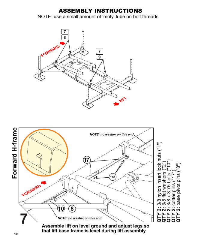
NOTE: use a small amount of 'moly' lube on bolt threadsASSEMBLY INSTRUCTIONS
Fe
et
an
d L
eg
s [
4 p
lac
es
]
Fo
rwa
rd C
ros
sm
em
be
r
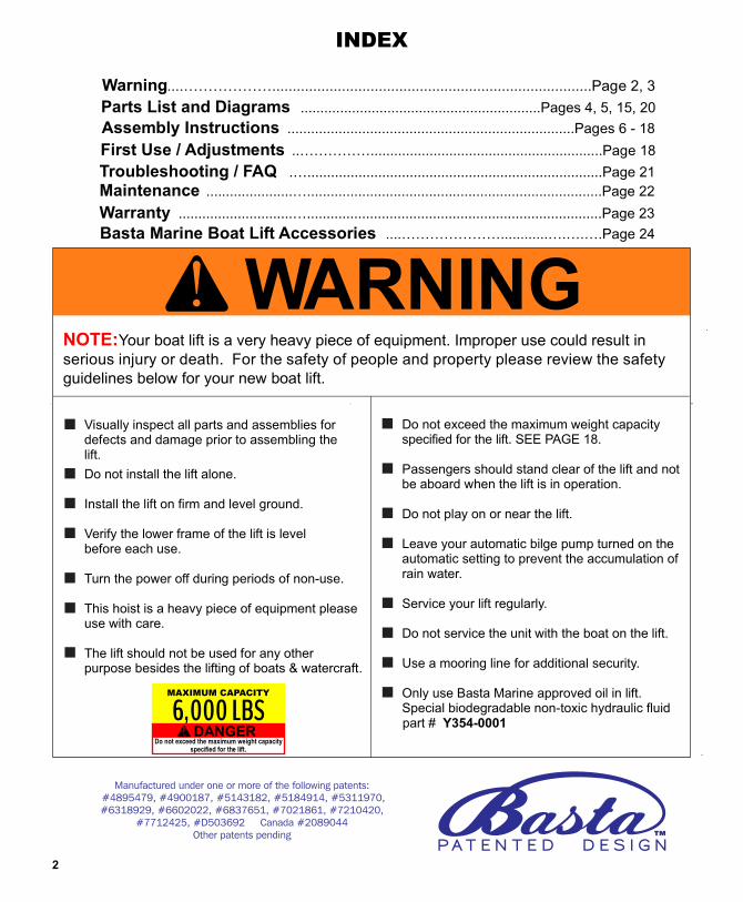
2
Aft
Cro
ss
me
mb
er
3A adjust legs sothat lift base frame is level during lift assembly.
ssemble lift on level ground and A adjust legs sothat lift base frame is level during lift assembly.
ssemble lift on level ground and
A adjust legs sothat lift base frame is level during lift assembly.
ssemble lift on level ground and
AA
BB
NOTE: the 3 different holes shown can be used for pin “14” to allow fine height adjustment after installation
14
1+2
DOWNto lock
22
NOTE: do not tighten bolt “22” until Step 22
1
10+2
CC
DD
1+2
10+2
TT
1+2
10+2
NOTE:SINGLE
NOTE:THREE
6
QT
Y 4
: 3
/8 x
3.7
5"
bo
lts
("1
0")
QT
Y 4
: 3
/8 n
ylo
n in
se
rt lo
ck
nu
ts (
"1")
QT
Y 8
: 3
/8 f
lat
wa
sh
ers
("2
")Q
TY
4:
leg
P p
ins
("1
4")
QT
Y 4
: 1
/2 x
1.0
" b
olts
("2
2")
1
1
1
2
3
1
NOTE: and adjust legs so that lift baseframe is level during lift assembly.
assemble lift on level ground
7
QT
Y 4
: 3
/8 x
3.7
5"
bo
lts
("1
0")
QT
Y 8
: 3
/8 f
lat
wa
sh
ers
("2
")Q
TY
4:
3/8
nylo
n in
se
rt lo
ck
nu
ts (
"1")
QT
Y 4
: 3
/8 x
3.7
5"
bo
lts
("1
0")
QT
Y 8
: 3
/8 f
lat
wa
sh
ers
("2
")Q
TY
4:
3/8
nylo
n in
se
rt lo
ck
nu
ts (
"1")
NOTE: use a small amount of 'moly' lube on bolt threadsASSEMBLY INSTRUCTIONS
Fe
et
an
d L
eg
s [
4 p
lac
es
]
Fo
rwa
rd C
ros
sm
em
be
r
2
Aft
Cro
ss
me
mb
er
3A adjust legs sothat lift base frame is level during lift assembly.
ssemble lift on level ground and A adjust legs sothat lift base frame is level during lift assembly.
ssemble lift on level ground and
A adjust legs sothat lift base frame is level during lift assembly.
ssemble lift on level ground and
AA
BB
NOTE: the 3 different holes shown can be used for pin “14” to allow fine height adjustment after installation
14
1+2
DOWNto lock
22
NOTE: do not tighten bolt “22” until Step 22
1
10+2
CC
DD
1+2
10+2
TT
1+2
10+2
NOTE:SINGLE
NOTE:THREE
8
4
4
5
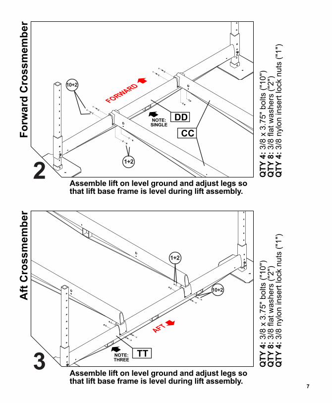
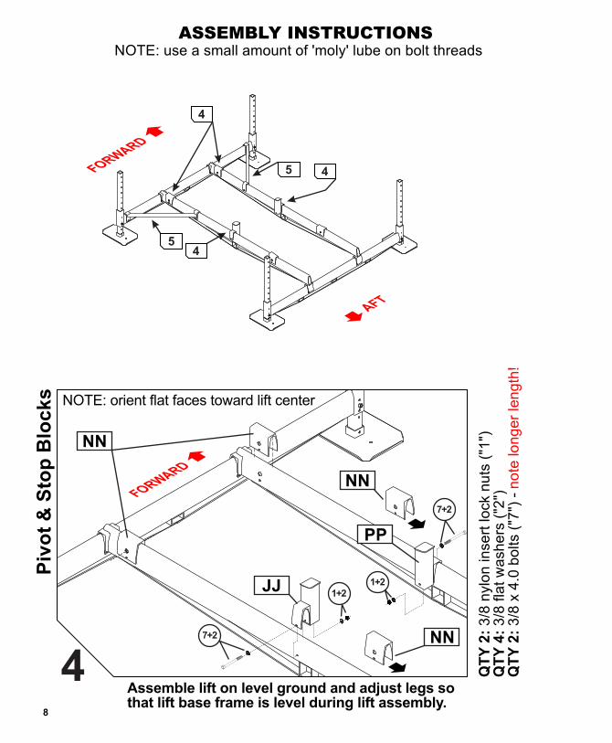
9
QT
Y 2
: 3
/8 n
ylo
n in
se
rt lo
ck
nu
ts (
"1")
QT
Y 4
: 3
/8 f
lat
wa
sh
ers
("2
")Q
TY
2:
3/8
x 4
.0 b
olts
("7
") -
NOTE: use a small amount of 'moly' lube on bolt threadsASSEMBLY INSTRUCTIONS
Piv
ot
& S
top
Blo
ck
s
A adjust legs sothat lift base frame is level during lift assembly.
ssemble lift on level ground and
4
5
QT
Y 8
: p
lastic
bu
sh
ing
s ("
MM
")
H-f
ram
e B
ush
ing
s [fw
d &
aft
]6
NOTE: forward H-frameis shown. Aft H-frame installation is the same
MM
MM
BOTHH-FRAMESare installedwith curved
side up
EE
no
te lo
ng
er
len
gth
!
4
NN
NOTE: orient flat faces toward lift center
7+2
1+21+2
NN
NN
7+2
JJ
PP
A adjust legs sothat lift base frame is level during lift assembly.
ssemble lift on level ground and
Fo
rward
Bra
ces
5
1+2
1+2
10+2
10+2
10+2
10+2
1+2
1+2
QT
Y 4
: 3
/8 n
ylo
n in
se
rt lo
ck
nu
ts (
"1")
QT
Y 8
: 3
/8 f
lat
wa
sh
ers
("2
")Q
TY
4:
3/8
x 3
.75
bo
lts
("1
0")
TT
UU
STEPPED END
STEPPED END
FLUSH END
FLUSH END

8
4
4
5
9
QT
Y 2
: 3
/8 n
ylo
n in
se
rt lo
ck
nu
ts (
"1")
QT
Y 4
: 3
/8 f
lat
wa
sh
ers
("2
")Q
TY
2:
3/8
x 4
.0 b
olts
("7
") -
NOTE: use a small amount of 'moly' lube on bolt threadsASSEMBLY INSTRUCTIONS
Piv
ot
& S
top
Blo
ck
s
A adjust legs sothat lift base frame is level during lift assembly.
ssemble lift on level ground and
4
5
QT
Y 8
: p
lastic
bu
sh
ing
s ("
MM
")
H-f
ram
e B
ush
ing
s [fw
d &
aft
]
6
NOTE: forward H-frameis shown. Aft H-frame installation is the same
MM
MM
BOTHH-FRAMESare installedwith curved
side up
EE
no
te lo
ng
er
len
gth
!
4
NN
NOTE: orient flat faces toward lift center
7+2
1+21+2
NN
NN
7+2
JJ
PP
A adjust legs sothat lift base frame is level during lift assembly.
ssemble lift on level ground and
Fo
rward
Bra
ces
5
1+2
1+2
10+2
10+2
10+2
10+2
1+2
1+2
QT
Y 4
: 3
/8 n
ylo
n in
se
rt lo
ck
nu
ts (
"1")
QT
Y 8
: 3
/8 f
lat
wa
sh
ers
("2
")Q
TY
4:
3/8
x 3
.75
bo
lts
("1
0")
TT
UU
STEPPED END
STEPPED END
FLUSH END
FLUSH END
11
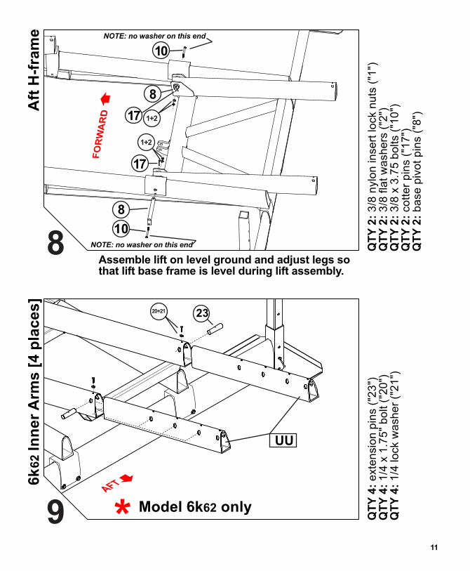
QT
Y 2
: 3
/8 n
ylo
n in
se
rt lo
ck
nu
ts (
"1")
QT
Y 2
: 3
/8 f
lat
wa
sh
ers
("2
")Q
TY
2:
3/8
x 3
.75
bo
lts
("1
0")
QT
Y 2
: co
tte
r p
ins
("1
7")
QT
Y 2
: b
ase
piv
ot
pin
s ("
8")
Aft
H-f
ram
e
8A adjust legs sothat lift base frame is level during lift assembly.
ssemble lift on level ground and
17
10
8
1+2
NOTE: no washer on this end
NOTE: no washer on this endNOTE: use a small amount of 'moly' lube on bolt threadsASSEMBLY INSTRUCTIONS
1+217
8
10
8
7
9
7
QT
Y 4
: e
xte
nsio
n p
ins
("2
3")
QT
Y 4
: 1
/4 x
1.7
5"
bo
lt (
"20
")Q
TY
4:
1/4
lo
ck
wa
sh
er
("2
1")
6k
62 I
nn
er
Arm
s [
4 p
lac
es
] 9
Model 6k62 only
2320+21
UU
10
QT
Y 2
: 3
/8 n
ylo
n in
se
rt lo
ck
nu
ts (
"1")
QT
Y 2
: 3
/8 f
lat
wa
sh
ers
("2
")Q
TY
2:
3/8
x 3
.75
bo
lts
("1
0")
QT
Y 2
: co
tte
r p
ins
("1
7")
QT
Y 2
: b
ase
piv
ot
pin
s ("
8")
Fo
rwa
rd H
-fra
me
7A adjust legs sothat lift base frame is level during lift assembly.
ssemble lift on level ground and
17
1+2
NOTE: no washer on this end
NOTE: no washer on this end
10 8
11
QT
Y 2
: 3
/8 n
ylo
n in
se
rt lo
ck
nu
ts (
"1")
QT
Y 2
: 3
/8 f
lat
wa
sh
ers
("2
")Q
TY
2:
3/8
x 3
.75
bo
lts
("1
0")
QT
Y 2
: co
tte
r p
ins
("1
7")
QT
Y 2
: b
ase
piv
ot
pin
s ("
8")
Aft
H-f
ram
e
8A adjust legs sothat lift base frame is level during lift assembly.
ssemble lift on level ground and
17
10
8
1+2
NOTE: no washer on this end
NOTE: no washer on this endNOTE: use a small amount of 'moly' lube on bolt threadsASSEMBLY INSTRUCTIONS
1+217
8
10
8
7
9
7
QT
Y 4
: e
xte
nsio
n p
ins
("2
3")
QT
Y 4
: 1
/4 x
1.7
5"
bo
lt (
"20
")Q
TY
4:
1/4
lo
ck
wa
sh
er
("2
1")
6k
62 I
nn
er
Arm
s [
4 p
lac
es
]
9
Model 6k62 only
2320+21
UU
10
QT
Y 2
: 3
/8 n
ylo
n in
se
rt lo
ck
nu
ts (
"1")
QT
Y 2
: 3
/8 f
lat
wa
sh
ers
("2
")Q
TY
2:
3/8
x 3
.75
bo
lts
("1
0")
QT
Y 2
: co
tte
r p
ins
("1
7")
QT
Y 2
: b
ase
piv
ot
pin
s ("
8")
Fo
rwa
rd H
-fra
me
7A adjust legs sothat lift base frame is level during lift assembly.
ssemble lift on level ground and
17
1+2
NOTE: no washer on this end
NOTE: no washer on this end
10 8
12 13
HH
QT
Y 4
: b
un
k p
ivo
t p
ins
("1
5")
15
15
Bu
nk
Rail C
arr
iers
[4
pla
ces]
bushings are
pre-installed
HH
QT
Y 4
: 1
/4 x
1.7
5”
bo
lts
("2
0")
QT
Y 4
: 1
/4 lo
ck
wa
sh
ers
("2
1")15
Bu
nk
Rail C
arr
iers
[4
pla
ces]
20+21
20+21
11
12
HH
15
HH
slots toward lift center
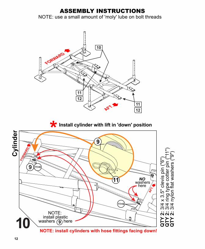
QT
Y 2
: 3
/4 x
3.5
" cle
vis
pin
("6
")Q
TY
2:
3/4
rin
g t
yp
e c
ott
er
pin
("1
1")
QT
Y 2
: 3
/4 n
ylo
n f
lat
wa
sh
ers
("9
")
Install cylinder with lift in 'down' position
11
10
12
NOTE: use a small amount of 'moly' lube on bolt threadsASSEMBLY INSTRUCTIONS
11
12
Cy
lin
de
r
10NOTE: install cylinders with hose fittings facing down!
NOTE: install plastic
washers here9
11+6
NO washers
here
11+6
9
9
11

12 13
HH
QT
Y 4
: b
un
k p
ivo
t p
ins
("1
5")
15
15
Bu
nk
Rail C
arr
iers
[4
pla
ces]
bushings are
pre-installed
HH
QT
Y 4
: 1
/4 x
1.7
5”
bo
lts
("2
0")
QT
Y 4
: 1
/4 lo
ck
wa
sh
ers
("2
1")15
Bu
nk
Rail C
arr
iers
[4
pla
ces]
20+21
20+21
11
12
HH
15
HH
slots toward lift center
QT
Y 2
: 3
/4 x
3.5
" cle
vis
pin
("6
")Q
TY
2:
3/4
rin
g t
yp
e c
ott
er
pin
("1
1")
QT
Y 2
: 3
/4 n
ylo
n f
lat
wa
sh
ers
("9
")
Install cylinder with lift in 'down' position
11
10
12
NOTE: use a small amount of 'moly' lube on bolt threadsASSEMBLY INSTRUCTIONS
11
12
Cy
lin
de
r
10NOTE: install cylinders with hose fittings facing down!
NOTE: install plastic
washers here9
11+6
NO washers
here
11+6
9
9
11

14 15
D13
D7
D9D8
D12
D6
D14
5. Test the lift on dry ground using the Up/Down Switch(D9) and the Key Fob Transmitters. Inspect thesystem for leaks.
1. The Hydraulic Pump will arrive fully assembled. Makesure all the connections are snug to prevent leaks orloss of power to the unit.
2. Install a Group 27 Marine Grade Battery as shownabove. Be sure to connect the Red Battery Cable (D12)to the positive terminal and the Black Battery Cable(D13) to the negative terminal.
NOTE: Ensure battery cables are correctly connected
3. Slide the Hydraulic Cylinder Hoses (D14) through theaccess hole in the side of the White Fiberglass Box(D10) and attach them to their correspondingQuick Couplers (D4, D5).
and their terminals are tight (use pliers).
4. Pass the cable from the Solar Panel through the same access hole as the hoses and plug it into the Remote Control Unit (D7A) as shown in the Page 20 diagram.
oneinch
hydraulic fluid level withlift in DOWN position
only add fluid with liftin DOWN position
D2
NO GAP!
D4
D5
Power unit
Ensure each Quick Coupler iscompletely seated and tight withno gap at the connection joint.Connection must be tight to open internalcheck valve and allow fluid to flow. USE PLIERS
Prevent unauthorized use -KEEP BOX LOCKED
NOTE: always turn unit OFF when not in use
DO NOT SUBMERSEKeep inside dry
D10
D11
Padlocknot included
14
SEEPAGE 20 FORREFERENCENUMBERS
QT
Y 4
: 1
/2 f
lat
wa
sh
ers
("1
8")
QT
Y 4
: 1
/2 T
HIN
nylo
n in
se
rt lo
ck
nu
ts (
"16
")
NOTE: use a small amount of 'moly' lube on bolt threadsASSEMBLY INSTRUCTIONS
Bu
nk
ra
ils
[2
pla
ce
s]
Do not over-tighten - bunks must rotate13
Install 4 nuts and washers only (as shown)Install other 4 in Step 12!
12
16+18
short sidesface in
KK
12 16+18
16+18
16+18
13
13

16 17
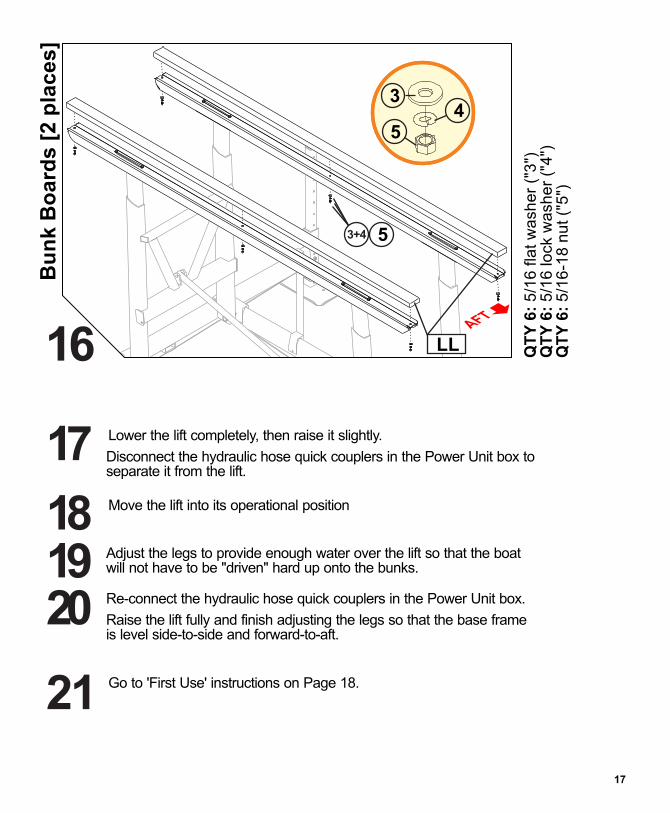
QT
Y 6
: 5
/16
fla
t w
ash
er
("3
")Q
TY
6:
5/1
6 lo
ck
wa
sh
er
("4
")Q
TY
6:
5/1
6-1
8 n
ut
("5
")
Lower the lift completely, then raise it slightly.
Disconnect the hydraulic hose quick couplers in the Power Unit box to separate it from the lift.
18
17Move the lift into its operational position
21
20
Go to 'First Use' instructions on Page 18.
Re-connect the hydraulic hose quick couplers in the Power Unit box.
Raise the lift fully and finish adjusting the legs so that the base frame is level side-to-side and forward-to-aft.
19 Adjust the legs to provide enough water over the lift so that the boat will not have to be "driven" hard up onto the bunks.
ASSEMBLY INSTRUCTIONSNOTE: use a small amount of 'moly' lube on bolt threads
Bu
nk
Bo
ard
s [
2 p
lac
es
]
16
3
54
LL
3+4 5
QT
Y 4
: 1
/2 f
lat
wa
sh
ers
("1
8")
QT
Y 4
: 1
/2 T
HIN
nylo
n in
se
rt lo
ck
nu
ts (
"16
")
Fin
al
bu
nk
ra
il b
olt
s
15
Move lift to raised position before this step
Do not over-tighten - bunks must rotate
16+18
15
15
16
1616
16 17
QT
Y 6
: 5
/16
fla
t w
ash
er
("3
")Q
TY
6:
5/1
6 lo
ck
wa
sh
er
("4
")Q
TY
6:
5/1
6-1
8 n
ut
("5
")
Lower the lift completely, then raise it slightly.
Disconnect the hydraulic hose quick couplers in the Power Unit box to separate it from the lift.
18
17Move the lift into its operational position
21
20
Go to 'First Use' instructions on Page 18.
Re-connect the hydraulic hose quick couplers in the Power Unit box.
Raise the lift fully and finish adjusting the legs so that the base frame is level side-to-side and forward-to-aft.
19 Adjust the legs to provide enough water over the lift so that the boat will not have to be "driven" hard up onto the bunks.
ASSEMBLY INSTRUCTIONSNOTE: use a small amount of 'moly' lube on bolt threads
Bu
nk
Bo
ard
s [
2 p
lac
es
]
16
3
54
LL
3+4 5
QT
Y 4
: 1
/2 f
lat
wa
sh
ers
("1
8")
QT
Y 4
: 1
/2 T
HIN
nylo
n in
se
rt lo
ck
nu
ts (
"16
")
Fin
al
bu
nk
ra
il b
olt
s
15
Move lift to raised position before this step
Do not over-tighten - bunks must rotate
16+18
15
15
16
1616

18
19
22
FIRST USE AND ADJUSTMENTS
Follow this “first use section” during your first loading of a boat onto the boat lift.These are required adjustments to make the lift work correctly.
1. Place the boat or water craft over the lift to the following specifications:
a. The craft should be centered between the bunks side-to side.
b. Move the craft forward to position its center of buoyancy near the bunks' centers. Centering Devices may be helpful when positioning your craft. See rear cover.
Disembark and raise the boat. If more than two inches of settling occurs, STOP, carefullylower the lift to remove the boat and re-level the lift. Continue repeating this step until theboat lift can be raised into the full Over-Center position without settling.
tm
3. Remove the boat. Verify that the lift frame is level. Re-level the framework if necessary.
NOTE: If you purchased a new boat, be sure it is within the weight capacity limits of the lift. Also remember that these adjustments will have to be done again to accommodate the new boat.
First test lift on dry ground for oil leaks, remote control function and correct operation.
2.
IMPORTANT: After installation, the legs MUST be adjusted so that the lift frame is level.
TM
Always turn unit OFF when not in use
Lift must move into Over-Center position when fully raised.H-frame arms should appear to be tilted slightly forward.
Maximum lifting capacity is 6000 pounds.DO NOT OVERLOAD!
Tighten the pinch boltsthat were installed in Step 1.
4. Check all bolts for proper tightness.
Do not exceed the maximum weight capacity specified for the lift.
6,000 LBSDANGER
MAXIMUM CAPACITY
Use these diagrams to help place the lift
22"
139"
84"
130"
117"36"
60"
Dimensions exclusive to model 6k51
are shown in [brackets]
[48"][26"][21"]
[72"]
28"
20 21
Remote Key Fobs
# R811-0009
D7BD7A
Remote Control Receiverwith Harness
STD.WIRING
NOT USED
NOT USED
LOWER (purp)
LAMP (yel or orn)
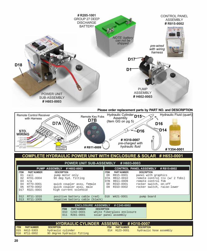
28Please order replacement parts by PART NO. and DESCRIPTION
PUMPASSEMBLY# H602-0003
# R285-1001GROUP 27 DEEP
DISCHARGEBATTERY
POWER UNITSUB-ASSEMBLY
# H603-0003
NOTE: batterycan not beshipped
D17
D1
CONTROL PANELASSEMBLY# R815-0002
pre-wiredwith wiring
harness
D18
COMPLETE HYDRAULIC POWER UNIT WITH ENCLOSURE & SOLAR # H653-0001
D1 D2 H701-0004 90 deg hyd. fitting D3 n/a D4 H770-0001 quick coupler assy, female D5 H770-0002 quick coupler assy, maleD17 R321-0001 high current solenoid
call pump motor only
D10 white fiberglass enclosureD11 R281-0001 solar panel assembly
C242-0001
ITEM PART NUMBER DESCRIPTION
ITEM PART NUMBER DESCRIPTION
PUMP ASSEMBLY # H602-0003
ENCLOSURE ASSEMBLY # C245-0002
POWER UNIT SUB-ASSEMBLY # H603-0003
D12 R711-1010 positive battery cable (red)D13 R711-1005 negative battery cable (black)
D18 W421-0001 pump board
D6 panel with graphicsD7A R812-0010 remote control rcv (w/ 2 fobs)D7B R811-0009 remote control fob D8 R310-0001 rocker switch, on-off D9 R310-0002 rocker switch, raise-lower
R815-0001ITEM PART NUMBER DESCRIPTION
CONTROL PANEL ASSEMBLY # R815-0002
Hydraulic Fluid (quart)
# Y354-0001
D14
D15
D16
D16
# H310-0007pre-charged with
hydraulic fluid
Hydraulic CylinderAssembly
(Item GG on pg 5)
HYDRAULIC CYLINDER ASSEMBLY # H310-0007
D15 hydraulic cylinderD16 H711-0002 90 degree hydraulic fitting
H412-5303 D14 hydraulic hose assembly
H123-0001 ITEM PART NUMBER DESCRIPTION ITEM PART NUMBER DESCRIPTION
TROUBLESHOOTING PROBLEMS AND FAQ
TROUBLESHOOTING PROBLEMS AND FAQ
Q: THE PUMP DOESN’T RUN A: Check the battery charge, recharge if necessary. A: Check the battery connections, clean and re-
secure if necessary.
Q: THE BATTERY WILL NOT HOLD A CHARGE
A: Verify that the loaded boat is not exceeding the weight capacity of the lift.
A: Ensure the solar panel is properly connected. A: Re-align the solar panel for proper exposure to
the sun.
A: Recharge the battery with a 10 ampcharger and check the charge again.
A: Have the battery tested. It may be old and require replacement.
A: If the lift is being used frequently during the day, it may be necessary to use a 110-volt maintainer/charger.
Q: THE REMOTE CONTROL IS NOT
FUNCTIONING PROPERLY A: Verify that the LED on each remote control
key fob comes on when each button is pushed. If the LED is not bright, the remote's range is reduced - replace the fob's battery.
A: Verify that the large power unit battery is charged and connections are tight.
A: Make sure the antenna wire on the power unit's remote receiver is located properly.
A: Reprogram the remote key fobs.
Q: THE HAND HELD REMOTE KEY FOBS NEED TO BE REPROGRAMMED
Q: DOES THE LIFT HAVE TO GO ALL THE WAY UP? A: YES - in order for your lift to function as intended
the lift must ALWAYS be stored in the full uprightposition when the boat is unattended.
Q: IS MY BOAT SECURE? A: Yes, once you verify that the lift is Over-Center™, switch off the power and lock the power unit box, there is less chance of theft.
Q: DO I NEED A MOORING LINE? A: Under most circumstances one mooring line is
sufficient to prevent the boat from drifting away if the lift inadvertently lowers or the water level rises.
Q: HOW MUCH SUN DOES THE SOLAR PANEL NEED?A: The panel should receive constant sun for at least 8
hours a day.
Q: WHAT IF I GET A NEW BOAT? A: Re-leveling the boat lift may be necessary.
A new lift will be required if the boat exceeds theweight capacity of your current lift.
Q: THE PUMP RUNS, BUT THE LIFT DOESN’T MOVE A: Check the 'quick couplers' in the Power Unit. If
they are not screwed together tight enough, built-incheck valves will not allow fluid to flow. See Page 12.
A: Check the fluid level. See Page 14.
FOR ASSISTANCE OR SERVICE:Contact your local dealer or call 1 - 866 - GO - BASTA
website: www.gobasta.com email: [email protected]
Q: IS THE HYDRAULIC FLUID SAFE FOR THE FISH? A: We use a special low-toxicity hydraulic fluid
that is safe for the environment. This oil is different than food-grade oil. Only use Basta Marine approved fluid in your hydraulic system.
Q: HOW DO I CHANGE THE HYDRAULIC FLUID? A: Our fluid should not require replacement for a
considerable amount of time. If yours has beencontaminated or the hydraulic power unit has beenreplaced, visit our web site at www.bastaboatlifts.comfor detailed instructions.
1 2 3 4Slide open smallcover for access
LEDs
7
6
4
2
This is the normalstate of the switches.
Push all the switches into the
OFF position.
Use the tip of a pen to push all of the switches into the
ON position.
Push switch #1 intothe ON position.
Push switch #1 back into the OFF position.
The green LED locatednear the solar panel
connector is on.
The green LED will stay on.
The red and green LEDs will flash alternately, showing that the memory is being erased.
The red LED will turn on,making the LED orange.
The green LED will stay on.
FIRST, ERASE THE MEMORY
THEN PROGRAM ONE FOB
REPEAT FOR EXTRA FOBS
Push the UP button on one of the fobs for a few seconds.
1 2 3 4
1 2 3 4
1 2 3 4
1 2 3 4
1 2 3 4
Wait 15 seconds.
1
3
5
10
9
Push switch #1 intothe ON position.
Push switch #1 back into the OFF position.
The red LED will turn on,making the LED orange.
The green LED will stay on.
Push the UP button on the other fob
for a few seconds.LEDs will alternate colors.
1 2 3 4
1 2 3 4
8
1
2
LEDs will alternate colors.
TWIST THIS RING TO POPTHE FOB HALVES APART
LED SHOULDBE BRIGHT
TURNS AUXILIARY LIGHTS ON
TURNS AUXILIARY LIGHTS OFF

20 21
Remote Key Fobs
# R811-0009
D7BD7A
Remote Control Receiverwith Harness
STD.WIRING
NOT USED
NOT USED
LOWER (purp)
LAMP (yel or orn)
28Please order replacement parts by PART NO. and DESCRIPTION
PUMPASSEMBLY# H602-0003
# R285-1001GROUP 27 DEEP
DISCHARGEBATTERY
POWER UNITSUB-ASSEMBLY
# H603-0003
NOTE: batterycan not beshipped
D17
D1
CONTROL PANELASSEMBLY# R815-0002
pre-wiredwith wiring
harness
D18
COMPLETE HYDRAULIC POWER UNIT WITH ENCLOSURE & SOLAR # H653-0001
D1 D2 H701-0004 90 deg hyd. fitting D3 n/a D4 H770-0001 quick coupler assy, female D5 H770-0002 quick coupler assy, maleD17 R321-0001 high current solenoid
call pump motor only
D10 white fiberglass enclosureD11 R281-0001 solar panel assembly
C242-0001
ITEM PART NUMBER DESCRIPTION
ITEM PART NUMBER DESCRIPTION
PUMP ASSEMBLY # H602-0003
ENCLOSURE ASSEMBLY # C245-0002
POWER UNIT SUB-ASSEMBLY # H603-0003
D12 R711-1010 positive battery cable (red)D13 R711-1005 negative battery cable (black)
D18 W421-0001 pump board
D6 panel with graphicsD7A R812-0010 remote control rcv (w/ 2 fobs)D7B R811-0009 remote control fob D8 R310-0001 rocker switch, on-off D9 R310-0002 rocker switch, raise-lower
R815-0001ITEM PART NUMBER DESCRIPTION
CONTROL PANEL ASSEMBLY # R815-0002
Hydraulic Fluid (quart)
# Y354-0001
D14
D15
D16
D16
# H310-0007pre-charged with
hydraulic fluid
Hydraulic CylinderAssembly
(Item GG on pg 5)
HYDRAULIC CYLINDER ASSEMBLY # H310-0007
D15 hydraulic cylinderD16 H711-0002 90 degree hydraulic fitting
H412-5303 D14 hydraulic hose assembly
H123-0001 ITEM PART NUMBER DESCRIPTION ITEM PART NUMBER DESCRIPTION
TROUBLESHOOTING PROBLEMS AND FAQ
TROUBLESHOOTING PROBLEMS AND FAQ
Q: THE PUMP DOESN’T RUN A: Check the battery charge, recharge if necessary. A: Check the battery connections, clean and re-
secure if necessary.
Q: THE BATTERY WILL NOT HOLD A CHARGE
A: Verify that the loaded boat is not exceeding the weight capacity of the lift.
A: Ensure the solar panel is properly connected. A: Re-align the solar panel for proper exposure to
the sun.
A: Recharge the battery with a 10 ampcharger and check the charge again.
A: Have the battery tested. It may be old and require replacement.
A: If the lift is being used frequently during the day, it may be necessary to use a 110-volt maintainer/charger.
Q: THE REMOTE CONTROL IS NOT
FUNCTIONING PROPERLY A: Verify that the LED on each remote control
key fob comes on when each button is pushed. If the LED is not bright, the remote's range is reduced - replace the fob's battery.
A: Verify that the large power unit battery is charged and connections are tight.
A: Make sure the antenna wire on the power unit's remote receiver is located properly.
A: Reprogram the remote key fobs.
Q: THE HAND HELD REMOTE KEY FOBS NEED TO BE REPROGRAMMED
Q: DOES THE LIFT HAVE TO GO ALL THE WAY UP? A: YES - in order for your lift to function as intended
the lift must ALWAYS be stored in the full uprightposition when the boat is unattended.
Q: IS MY BOAT SECURE? A: Yes, once you verify that the lift is Over-Center™, switch off the power and lock the power unit box, there is less chance of theft.
Q: DO I NEED A MOORING LINE? A: Under most circumstances one mooring line is
sufficient to prevent the boat from drifting away if the lift inadvertently lowers or the water level rises.
Q: HOW MUCH SUN DOES THE SOLAR PANEL NEED?A: The panel should receive constant sun for at least 8
hours a day.
Q: WHAT IF I GET A NEW BOAT? A: Re-leveling the boat lift may be necessary.
A new lift will be required if the boat exceeds theweight capacity of your current lift.
Q: THE PUMP RUNS, BUT THE LIFT DOESN’T MOVE A: Check the 'quick couplers' in the Power Unit. If
they are not screwed together tight enough, built-incheck valves will not allow fluid to flow. See Page 12.
A: Check the fluid level. See Page 14.
FOR ASSISTANCE OR SERVICE:Contact your local dealer or call 1 - 866 - GO - BASTA
website: www.gobasta.com email: [email protected]
Q: IS THE HYDRAULIC FLUID SAFE FOR THE FISH? A: We use a special low-toxicity hydraulic fluid
that is safe for the environment. This oil is different than food-grade oil. Only use Basta Marine approved fluid in your hydraulic system.
Q: HOW DO I CHANGE THE HYDRAULIC FLUID? A: Our fluid should not require replacement for a
considerable amount of time. If yours has beencontaminated or the hydraulic power unit has beenreplaced, visit our web site at www.bastaboatlifts.comfor detailed instructions.
1 2 3 4Slide open smallcover for access
LEDs
7
6
4
2
This is the normalstate of the switches.
Push all the switches into the
OFF position.
Use the tip of a pen to push all of the switches into the
ON position.
Push switch #1 intothe ON position.
Push switch #1 back into the OFF position.
The green LED locatednear the solar panel
connector is on.
The green LED will stay on.
The red and green LEDs will flash alternately, showing that the memory is being erased.
The red LED will turn on,making the LED orange.
The green LED will stay on.
FIRST, ERASE THE MEMORY
THEN PROGRAM ONE FOB
REPEAT FOR EXTRA FOBS
Push the UP button on one of the fobs for a few seconds.
1 2 3 4
1 2 3 4
1 2 3 4
1 2 3 4
1 2 3 4
Wait 15 seconds.
1
3
5
10
9
Push switch #1 intothe ON position.
Push switch #1 back into the OFF position.
The red LED will turn on,making the LED orange.
The green LED will stay on.
Push the UP button on the other fob
for a few seconds.LEDs will alternate colors.
1 2 3 4
1 2 3 4
8
1
2
LEDs will alternate colors.
TWIST THIS RING TO POPTHE FOB HALVES APART
LED SHOULDBE BRIGHT
TURNS AUXILIARY LIGHTS ON
TURNS AUXILIARY LIGHTS OFF

22
23
Product Information
Serial #:_________________________________________
Date of purchase: _________________________________
Purchased from: __________________________________
Contact name: ___________________________________
Phone number: __________________________________
Notes: __________________________________________
________________________________________________
________________________________________________
BASTA MARINE MOORING PRODUCTS LIMITED WARRANTY
WARRANTY: Basta Inc. dba Basta Boatlifts and Basta Marine (“Company”) warrants its Products for non-commercial use for a period of three (3) years, to the original Purchaser (“Purchaser”) against manufacturing defects in all Product materials and workmanship beginning from date of purchase of the Product from Company If the Product is purchased from an authorized Company Reseller, the warranty term begins upon the date the Product is sold to the end Purchaser or three (3) months from the date the Product is shipped form Company, whichever occurs first. Under the following terms and conditions:
NOTICE REQUIREMENTS AND REMEDIES: If the Purchaser discovers a defect, the Company, or its authorized Company dealer or agent, will, at the Company's options: (1) repair the Product, (2) replace the defective part, or (3) refund the purchase price of the Product upon confirmation by Company the Product is defective, provided that the Company receives notice of the defect from the Purchaser or Company authorized agent before the warranty period lapses. Product changes caused by age or environment (such as marine growth, heat corrosion or electrolysis) shall not constitute a defect. Confirmation of the defect shall require that reasonable proof of the defect be provided by Purchaser to Company or Company authorized agent, and may include that the Product or part be returned to Company for inspection at Purchaser's initial expense. This warranty shall not apply if Company receives notification after the before-stated deadline, regardless of when the defect occurred or was discovered, and regardless of the reason for the delay in notification. “Notification” shall be deemed to have occurred when the Purchaser or Company authorized agent sends written notice to Company by fax or by e-mail and when receipt is confirmed by Company's response.
EXCLUSIONS: This warranty does not apply to damages caused by or due to : (1) accident (including, without limitation, collision, fire, flood, wind, ice or any other natural disaster or acts of God), abuse, misuse, overloading, out of level or improper boat loading (i.e.: not fully on, too far on, or crooked on lift), or (2) faulty assembly or installation in the event such assembly or installation was not performed by a Company employee or Company authorized agent. Company is not responsible for determining the weight or dimensions of Purchaser's boat, and Purchaser is advised that published boat specifications are often inaccurate. This warranty is void if the Product has been modified without the permission of the Company or if any Company serial number has been removed or defaced. Normal maintenance requires an annual inspection of the Product by a Company employee or Company authorized agent, including bolts, pins, hydraulics, pump, electronics, and welds and failure to undertake such maintenance may constitute “abuse”. Lift components' fluid level and condition, including battery water and acid, hydraulic fluid and strainer cleaning are maintenance items and are not covered by this warranty. Zincs, ropes, batteries, cosmetic concerns and custom coatings are not covered by this warranty. Batteries supplied by Company that are maintained in top operating condition by Purchaser are warranted for a period of one (1) year. If any Company Product is used in brackish or salt water, the Purchaser agrees that proper maintenance requires that the Purchaser shall attach to the Product, maintain and regularly check sacrificial anodes, also known as “zincs,” in order to prevent electrolysis from damaging the lift metals, and that failure to attach and maintain the zincs constitutes “abuse.” This warranty does not void or alter any rights the Purchaser may have against authorized agents or suppliers of component parts.
LIMITATIONS: To the maximum extent permitted by law except as expressly stated herein, there are no warranties, expressed or implied, by operation of law or otherwise, of the Product furnished under this Agreement. Seller disclaims any implied warranty of merchantability or fitness for a particular purpose. The sole remedy for liability of any kind shall be limited to the remedies provided in this warranty and shall in no event include any incidental, indirect, special or consequential damages or loss of use, revenue or profit. Should the company nevertheless be found liable for any damages the total liability of the company shall be limited to the purchase price of the product
MAINTENANCE tmYour Basta Boatlift requires very little maintenance once installed.
Occasionally wipe the solar panel with a clean, damp cloth to preserve its charging performance.
Every 6 months, we recommend:
Inspect the hoses, cylinders and fittings for leaks and wear.
Check the wire terminals for snugness and corrosion.
Check the hydraulic fluid and battery electrolyte levels:
The battery electrolyte should be slightly above the indicator ring in each cell.
Carefully add DISTILLED water if necessary. Do not over-fill.
The hydraulic fluid level should be about one inch below the top of the reservoir with the lift DOWN.
DO NOT add fluid with the lift in the raised position!
Use only Basta approved fluid.We recommend Chevron Clarity® AW ISO 32 or CITGO Aquamarine® 46 hydraulic oils.
DATE: WHAT WAS DONE:

Protect your boat from the harmful effects of the sun, wind and snow.
ACCESSORIES FOR MOST BASTA BOATLIFTS
CANOPIES
Centering DevicesThese vertical reference guidesgently center your boat over thelift and provide a constantreference point for front/backpositioning.
Bow StopThis adjustable bow stop assistsin proper placement of your boatby gently stopping its forward motion.
Side Deck BracketsOne of the many advantages ofusing a boat lift is the increasedaccessability to your boat formaintenance. These bracketsallow a side deck to be attachedto the existing boat lift orcanopy legs.
Load Guides Designed to make loadingyour boat straight and trueamazingly easy - even incross winds and active water.
Light kitInstall these lights above orbelow the water. They turn onwith your remote control key fob.
Power Unit Support BracketSafely secure the power unit boxto a boatlift canopy leg or the side of your dock.
For additional information and images visit our web site at www.gobasta.com or contact Basta Marine at 1-866-GOBASTA for a catalog.
TM
Low profile silhouette
Sturdy and wind resistant
Attaches to a variety of lifts
Wide choice of colors
Durable Weblon® vinyl top
Optional Sunbrella® tops
22, 24, 26, 30, 33, 39 foot lengths
10 and 12 foot widths
All aluminum design
Custom extrusions - no welds
Solø™ 33 canopy
Basta Solø™ canopy features: