over-voltage prevention solutions for 220 kv … solutions for preventing over-voltage of cs2bat2...
TRANSCRIPT
International Journal of Applied Engineering Research ISSN 0973-4562 Volume 12, Number 18 (2017) pp. 7754-7769
© Research India Publications. http://www.ripublication.com
7754
Over-Voltage Prevention Solutions for 220 kV Distribution Substation to
Enhance Power System Stability: A Case Study in Vietnamese Power System
Doan Duc Tung Department of Engineering and Technology, Quy Nhon University, Binh Dinh, Vietnam.
Orcid ID: 0000-0002-7560-1607
Abstract
This paper proposes the solutions to prevent over-voltage for
the 220 kV distribution substations with several different
voltage levels. The motivation comes from the failures of
surge arrester number 2 of phase B at the transformer number
2 (CS2BAT2) of the Vietnamese 220 kV Thainguyen
substation due to the over-voltage. The main objective is to
enhance the operating stability of a scattered connected
power network between substations. The Vietnamese 220 kV
Thainguyen substation has the complexity structure, operates
on three voltage levels of 220/110/35/22 kV, and connects
the Chinese 220 kV Malutang. During the operating period,
the operating voltage at the 220 kV bus is equal to 1.15 p.u..
This high voltage will put the transformer into magnetic
saturation, so that the CS2BAT2 has been faced with serious
failures. This paper proposes the solutions for preventing
over-voltage located CS2BAT2 to enhance the Thainguyen
substation stability. These proposed solutions are developed
from the operating ideas based on the flexibility in
instantaneously changing the system configuration. The
effectiveness of the proposed solutions are confirmed by the
simulation results based on (i) using Electromagnetic
Transients Program-Restructured Version (EMTP-RV) to
calculate and re-analyze the practical event at 0 : 12 AM on
June 17, 2015, (ii) comparing the obtained results between
the use of EMTP-RV and the recorded relay, on those bases
to continue making other necessary case. It was observed that
the proposed solutions could apply to immediately solve the
difficulties encountering in the Vietnamese 220 kV
Thainguyen substation.
Keywords: Surge arrester (SA), over-voltage, Vietnamese
system, 220kV distribution substation, Electromagnetic
Transients Program-Restructured Version (EMTP-RV)
INTRODUCTION
In early days, the demand to the electric energy is little, so
that the small power station was built to supply the heating
and lighting loads. However, when the social, political, and
technological aspects develop, the demand of electricity
power grows rapidly, resulting in building big power station at
favorable places. The long transmission distances over weak
grids, highly variable generation patterns, and heavy load,
resulting in the increase of the scale and complexity of power
systems and the large network of conductors between the
power station and the consumers, continuously face the
disturbances like sudden change in load, sudden thrown of
load, transient, switching etc. [1]
The distribution substation is an important electrical part for
the electric power supply system used to transfer the electric
power from the transmission system to the distribution system
of an area. In a scattered connected power network between
substations, the series inductances and shunt capacitances
long the long transmission lines can cause significant voltage
variations between high and low load periods [2]. When the
transmission line is loaded below the surge impedance load,
the line experiences a voltage rise due to the natural shunt
capacitance drawing charging current through the series
inductance [3], leading to the bus at receiving-end also
experiences a voltage rise. During the periods of light loading
on the transmission line, the bus at receiving-end happen
over-voltage. Moreover, the over-voltage caused by lightning
or switching surges [4].
Over the years, there has been a growing concern about the
issue of over-voltage for distribution substation [5]. The over-
voltages can be classified as the transient over-voltage,
harmonic resonance over-voltage, over-voltage resulting from
ferro-resonance, and sustained over-voltage, in which the
transient over-voltage is an outcome of witching operations on
the long transmission line or the capacitive devices, and may
result in the surge arrester failures, leading to the damage of
transformers and other power system equipments [68].As
well as preventing damage to the equipments in substation due
to fault current, the over-voltage protection is also necessary
to ensure that, the excessive voltage do not cause damage or
lead to unnecessary outages.
In recent years, the economic tempo in the Vietnam has been
developed rapidly; the total load has increased continuously.
Therefore, the Vietnamese power system has been faced with
the serious power system blackouts, such as on Dec. 27, 2006;
July 20, 2007; Apr. 09, 2007; and the latest event on May 22,
2013 [9]. Therefore, this study proposes the solutions to
prevent over-voltage for the Vietnam 220 kV Thainguyen
substation to project the equipments as the surge arrester,
transformers, and so on and to enhance the system stability.
The motivation comes from the failures of surge arrester
number 2 of phase B at the transformer number 2 (CS2BAT2)
(denoted the red symbol in Figure 1) of the Vietnamese 220
International Journal of Applied Engineering Research ISSN 0973-4562 Volume 12, Number 18 (2017) pp. 7754-7769
© Research India Publications. http://www.ripublication.com
7755
kV Thainguyen substation due to the transient over-voltage.
The substation has complexity structure, operates on several
different voltage levels of 220/110/35/22 kV with the total
capacity of 626 MVA, placed at Quantrieu, Thainguyen urban
area, playing an important role in the electric distribution and
transmission of the North area. It is received the electrical
power from the several different substations through the long
transmission lines and most notably the line connects between
Malutang substation of China and Thainguyen substation of
Vietnam, as shown Figures 1 and 6.
During the operating period, the recorded results from relay is
provided by Power Transmission Company 1 (PTC1), the
operating voltage at the 220 kV bus is equal to 1.15 p.u.. This
high voltage will put the transformer into magnetic saturation
[10], causing core heating and harmonic current. SA called
upon to operate at excessive sustained energy during periods
of high voltage will have reduced tripping capability [11].
However, for the Vietnamese 220 kV Thainguyen substation,
the CS2BAT2 has been faced with serious failures, such as on
April 22, 2012; July 17, 2014; and June 17, 2015. Typically,
the event is at 0 : 12 AM on June 17, 2015, the damage has
occurred on the CS2BAT2, the voltage and current at the bus
C22 before and after producing the fault are plotted in Figures
10 and 11, resulting in the broken CS2BAT2. The scene after
fault shows in Figure 2.
The 220 kV bus of Thainguyen substation is connected to the
Chinese Malutang substation through transmission line
between Thainguyen and Malutang (Thainguyen-Malutang)
about 347.9 km. During the operating period, the sending-end
voltage (220 kV bus of Malutang substation) is not controlled
despite the operating structure at Thainguyen substation. In
addition, the line Thainguyen-Malutang can cause significant
voltage variations between high and low load periods. It can
be realized that the main case occurs this damage due to the
over-voltage bus at receiving-end (220 kV bus of Thainguyen
substation) due to the system that receives power from the
Malutang station.
In this paper, solutions for preventing over-voltage of
CS2BAT2 are proposed to enhance the 220 kV Thainguyen
substation stability. These proposed solutions are developed
from the operating ideas based on the flexibility in
instantaneously changing the system configuration. The
effectiveness of the proposed solutions are confirmed by the
simulation results based on (i) using Electromagnetic
Transients Program-Restructured Version (EMTP-RV) to
calculate and re-analyze the practical event at 0:12 AM on
June 17, 2015, (ii) comparing the obtained results between the
use of EMTP-RV and the recorded relay, on those bases to
continue making other necessary case study. The main new
contributions of this paper is to propose an optimal solution
for preventing over-voltage of the 220 kV substation that
receives the power from two different countries.
The remaining part of this paper is organized as follows:
Section 2 presents the description and modeling of main
components used in the work described in the paper. The case
simulation and impacts analysis when producing the danger to
SA are described in Section 3 and 4, respectively. Section 5
proposes the solutions for preventing the over-voltage of SA.
Lastly, the conclusions are presented in Section 6.
76
T202-2
T202-7
272-0 T202
TBN-403
3th order fillter
26,064 MVAr
KH401-2
-28
-06
-48
444
TD44250KVA
c 12
c 11
c 19
a t 1
CS2AT1
CS1T3
Dong Hy
c 32
172 Go Dam
(E6.3)
21,2km
c 31
c 22
c 21
CS9AT1
CS4T3
TUC43 TUC44
TUC91
c 91 c 43 c 44
333
931
433
VSIP 63/63/63MVA 115/35/22KV
Y
a t 2
434
c 42
432
172 Cao Ngan
(A60)
CS4AT2
471
472
474
-7
272
TU271
TB
D202
C46
TD91 250KVA
-76
-75
-15
PAUWELS 250/250/85MVA225/115/23KV
/
APEX 250/250/63MVA225/121/10KV
-38
171 XM TN
(E6.8)
17km
334
381
Dai TuTUC42
TN City
-18
TUC91-14
TUC43-34TUC44-44
232
271
402
-28
CS4KH403 CS4KH405 CS4KH407
KH403
133-0 134-0
473
-2
273 Phu Binh
(E6.16)
27,1km
-1
D05
-2 -1
D04
-38
-35-3
-15
-2 -1
D03
-7
TU275
-76
-75
275
231
-15
-2 -1
D01
-38
-35-3
-14
212
CS2AT2
TUC22 TUC21
-25
-2-1
D02
-7
TU274
-76
-75
274
-2 -1
D07
-7
TU273
-76
-75
273
-25
-1 -2
D06
-24
-1-2-25 -15
220KV
-24
-38
272 Tuyen Quang
(A14.0)
134km
274 Ha Giang
(E22.4)
231,7km
271, 272 BG
(E7.6)
62,2km
TU272B-6
-64
-65
-26
-7
-76
-74
TU272ACS272
273 Ha Giang (E22.4)
267,7km
CS4C46 KH403-2 KH405-2 KH407-2
-28 -28
TBN-405
5th order fillter19,21MVAr
TBN-407
7th order fillter
15,184MVarKH401 TCR
108MVAr
CSC21CSC22
c C
941-1
-76 -76
Dong Hy
t 3 VSIP 63/63/63MVA
115/35/22KVY
t 4
CS3T3
TN City Phu Luong
-76 -76
0,4KV
0,4KV
c Cc Cc C
CSKH401
CS274
CS1AT2 CS1AT1
-38
-35-3
-9
TU171
-38
-35-3
-9-98 -98
-7
-76
-75
133
-25
-2 -1
-15
171
-25
-2 -1
-15
134
-25
-2 -1
-15
112
-2 -1
-15
TUC19
TUC12-2
-24
-28
TUC12
CSTUC12
172
-25
-2 -1
-15
TUC11-1
-14
-18
TUC11
CSTUC11
-9-96
TU172
-7
-76
-75
-9-96
171 Quan Trieu
(E6.11)
7,6km
173
-25
-2 -1
-15
TU173
-7
-76
-75
-9-96
174
-25
-2 -1
-15
-7
-76
-75
-9-96
-95-9
-94
100
-25
-2 -1
-38
-35-3
-9
131
-25
-2 -1
175
-25
-2 -1
-9
-7
-76
-75
176
-25
-2 -1
-9
-7
-76
-75
-38
-35-3
-9
132
-25
-2 -1
177
-25
-2 -1
-9
-7
-76
-75
178
-25
-2 -1
-9
-7
-76
-75
TU174 TU175 TU176 TU177 TU178
110KV
-15-15
D08
KH405 KH407
E01 E05 E03 E04 E07 E08 E06 E09 E10 E11 E12 J13 J14E02
-15 -25
-1 -2-15 -25
-1 -2
-38
-35-3
-38
-35-3
-1 -2
-15 -25
-7
-75
-76
380
-1 -2
-15 -25
-7
-75
-76
377
-1 -2
-15 -25
-7
-75
-76
376
-1 -2
15 -25
-7
-75
-76
373
-1 -2
-15 -25
-7
-75
-76
372
-1 -2
-15 -25
-7
-75
-76
312
-1 -2
-15 -25
Dong Hy
TUC31-1
-18
-14TUC32-2
-28
-24
TUC31 TUC32
CSTUC31 CSTUC32
CS3T4
Gang Thep
412-
2
-25
171 An Khanh
(A6.15)
5,6km
412
CS4T4
-38-38
CS1T4
172 XM TN
(E6.8)
17km
Bac Kan
(E26.1)
82,2km171 Cao Ngan
(A60)
Dai Tu Gang Thep
Figure 1: One Line Diagram of the Vietnamese 220 kV Thainguyen substation.

International Journal of Applied Engineering Research ISSN 0973-4562 Volume 12, Number 18 (2017) pp. 7754-7769
© Research India Publications. http://www.ripublication.com
7756
Figure 2: Broken surge arrester number 2 of phase B at the
transformer number 2 (CS2BAT2) after facing the over-
voltage.
DESCRIPTION AND MODELING FOR MAIN
COMPONENTS OF POWER SYSTEM
Substation structure
The 220 kV Thainguyen substation consists of two automatic
transformers (AT) of 250/250/85 MVA-220/110/22 kV, two
transformers (T) of 63/63/63 MVA-110/35/22 kV, seven
feeders (switching bays) of 220 kV, fourteen switching bays
110 kV, nine switching of 35 kV, ten switching bays of 22 kV,
a 220 kV series capacitor unit with fixed series compensation
(FSC) of 35-Ohm, and a static var compensator (SVC) of 50
MVAr. The one line diagram and location of substations are
shown in Figures 1 and 3, respectively.
Figure3: The map of showing the connected transmission line
between substations.
Surge arrester
The over-voltage protection to high voltage network is
performed by the combination of several different devices, in
which SA is a protective equipment placed at the electrical
station to protect the equipment against over-voltage caused
by the lightning and switching surge and alternating current
(AC) voltages [1213], as shown in Figure 1. The SA has two
types, the first one is the resistor element made of the silicone-
carbide (SiC); there contains the air gap in the SiC. Another
one is the non-linear resistor element made of the metal-oxide
(MO); there is no air gap in the MO. Nowadays, the SAs with
the MO is selected to install into the electrical power system
to be more than the SiC because of the its highly non-linear
voltage-current (V-I) characteristic [13]. MO surge arresters
are used to protect the medium- and high-voltage system and
the insulation of equipment against over-voltage [14]. SAs are
often subjected to the high-voltage stresses because of the
high earth resistance of the grid grounding system.
Assessment of the dynamic characteristic of MO surge
arrester under such over-voltage stresses to be therefore an
important aspect of insulation coordination [1516].
For the 220 kV Thainguyen substation, the MO surge arrester
PEXLIM Q192-XH245 [17] is used and placed at CS2AT2
location having the voltage-current (V-I) characteristic [18]
and temporary over-voltage (TOV) strength factor, as shown
in Figure 4a and the parameters are listed in Table 1[17].
For using this AS, the highest energy absorption capability of
SA at the TOV condition is about 4.5 kJ/ kV, as shown in
Figure 4b. Therefore, the highest absorption energy of the
surge arrester PEXLIM Q192-XH245 is 0.864 MJ at the
TOV’s endured time of 17 minutes and this absorption energy
after enduring the over-voltage time of 28 hours is equal to
0.8 MJ.
Table 1. Parameters of surge arrester PEXLIM Q192
Max. system
voltage
Rated voltage Max. continuous operating voltage TOV capability Max. residual voltage with current wave
As per IEC As per ANSI/IEEE 30/60 s 8/20 s
Um Ur Uc MCOV 1 s 10 s 0.5 kA 1 kA 5 kA 10 kA 20 kA 40 kA
kV kV kV kV kV kV kV kV kV kV kV kV
245 192 154 220 211 369 381 369 429 452 497 555

International Journal of Applied Engineering Research ISSN 0973-4562 Volume 12, Number 18 (2017) pp. 7754-7769
© Research India Publications. http://www.ripublication.com
7757
(a)
(b)
Figure 4: Surge arrester of PEXLIM Q192-XH245:
(a) voltage-current (V-I) characteristic [18]; and (b) temporary over-voltage (TOV) capability [17].
Transformer
The over-voltage will cause the magnetic saturation of
transformer [10], leading to this serious damage for the
equipments in substation. The Thainguyen substation has four
transformer, in which two 250 MVA-220/110/22 kV automatic
transformers; group of winding Y0/-11; short-circuit voltage
UnHV-Ter% of 10.27, UnHV-LV% of 30.53%, and UnTer-LV% of
17.9% at the temperature 750C; no load loss of 57,797 kW;
and another two 63 MVA-110/35/22 kV transformers; group
of winding Y0/-11/Y0; short-circuit voltage UnHV-Ter% of 11,
UnHV-LV% of 34.8%, and UnTer-LV% of 21.6% at the
temperature 750C; no load loss of 45 kW. The equivalent “T”
of transformers shown in Figure 5a; in which, for 250 MVA,
the impedances are ZHV of 0.2 + j10.9 Ohm, ZLV of 0.2 + j14.1
Ohm, and ZTer of 0.2 + j15.2 Ohm; and for 63 MVA, the
impedances are ZHV of 1.57 + j103 Ohm, ZLV of 1.11 j10
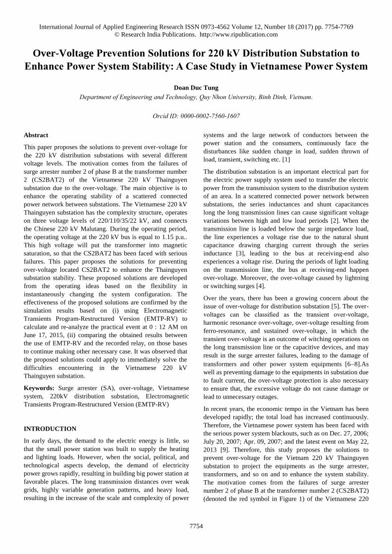
Ohm, and ZTer of 6.69 + j191 Ohm. Figure 5b plots the
saturation characteristic. The transformers are modeled using
EMPT-RV.
Static Var Compensator
The SVC is one of the most notable series of the FACTS
devices. The basis control scheme is designed on the basis of
the quick an reliable means of exchanging capacitive and/or
inductive to regulate the voltage, control reactive power, and
dampen oscillation [19]. In this paper, SVC can be installed at
the buses to maintain and/or control particular parameters of
the electrical power system by exchanging capacitive and/or
inductive current. As seen in Figure 1, A 50 MVAr SVC,
including of a thyristor controller reactor (TCR) unit of -108
MVAr and three harmonic filter units of the frequencies 3rd,
5th, and 7th having the reactive powers 26 MVAr, 19 MVAr,
and 15 MVAr, respectively, is placed at bus C46 of
Thainguyen substation. For this proper, the dynamic and
transient stability will be enhanced. The TCR provides
continuously controllable lagging VARs [20]. The harmonic
filters are used to filter the frequencies 3rd, 5th, and 7th and to
prove the reactive power. The modeling of SVC control is
modeled by EMTP-RV, as shown in Figure 6a. The voltage-
current characteristics of a SVC are shown in Figure 6b,
describing the variation between the voltage and current or
reactive of the installed SVC bus.
(a)
International Journal of Applied Engineering Research ISSN 0973-4562 Volume 12, Number 18 (2017) pp. 7754-7769
© Research India Publications. http://www.ripublication.com
7758
(b)
Figure 5: The transformers property: (a) The equivalent
“T”; and (b) The saturation characteristic.
(a)
(b)
Figure 6: The SVC model: (a) the detail model in
Electromagnetic Transients Program-Restructured Version
(EMTP-RV); and (b) the voltage-current characteristics
Transmission Network and Connected Feeders
Figure 7a shows the transmission network connecting between
the Thainguyen substation and the other substations. As can
be seen that the line MalutangThainguyen has the total line
length 347.9 km mounted on the tower structure of the
transmission line with another one. The lines Malutang-
Hagiang, Hagiang-TDTuyenquang and Hagiang-Baccan used
the aluminum conductor steel reinforced (ASCR)400/51 and
2xASCR 330/41 types [21]. The line TĐTuyenquang
Tuyenquang used 2xASCR 330/43 and transposed. The line
Tuyenquang-Thainguyen did not transpose. The tower
structure of the transmission line shows in Figure 6b.
Transmission tower is modeled in EMTP-RV using
philosophy of lossless line, in this loss line model each section
of tower in represented with a calculated surge impedance and
transmission line is modeled with a frequency dependent J
marti model based on the geometrical data of the tower, the
surge impedance, and the insulator details. In addition, the
earth resistance of the tower was approximated with a current
depending relation. The resistance and inductance of the
positive sequence are constant up to approximately 1.0 kHz
that cover the frequency range of harmonic over-voltage
phenomena.
SIMULATION
The simulation cases are reported in this section to illustrate
the suitabitliy of the obtained results of using EMTP-RV
sofware compared to that of actual relay. These actual results
provided by the Operation Unit. Here the result is represented
as four figures, (i) Normal condition (Figures 8 and 9) and (ii)
Transient condition (Figures 10 and 11). The representation of
figures are shown below:
Under Normal Condition This simulation was done on the
normal condition. Three phase voltages at the bus CC22 and
three phase currents on circuit breaker 272 using AMTP-RV
are shown in Figure 8, whereas that are recorded by Relay as
shown Figure 9.
Under Transient Condition This simulation was done on the
fault development at 0 : 12 AM on 17 Dec., 2016, this damage
resulted in opening circuit breaker 232.
This fault represents below: (i) The SVC is outage after time
0.3 sec. (ii) The circuit breaker 171 is opened after time 0.5
sec, resulting with the interruption of loads at bus 110 kV, so
that the transformer AT2 operated no load. (iii) The circuit
breaker 232 will be opened when the CS2BAT2 absorbs the
energy over its rated energy, in other words, the CS2BAT2 is
broken.
Figure 10 plots three phase voltages at the bus CC22 and three
phase currents on circuit breaker 272 using AMTP-RV,
whereas figure 11 plots that using the recorded Relay.
Observing the obtained results from using EMTP-RV analyses
and the recoded Relay in Figures 811, their effectiveness
seems to be similar all over the time. Therefore, we can be
concluded that the model, simulation, and analyses, using
EMTP-RV software, have reasonable grounds for making next
steps.
+ A?i
I_SVC
ABC_22kV
Qp3
Q
Filters
HF3
Filters
HF5ABC_110kV
Filters
HF7
TCR
abcPrimabcSec
Control
ab
c P
TCR

International Journal of Applied Engineering Research ISSN 0973-4562 Volume 12, Number 18 (2017) pp. 7754-7769
© Research India Publications. http://www.ripublication.com
7759
Figure 12 plots the highest energy absorption capability of
some of surge arresters in the station. Oberserving from
figures, it can be shown that the energy in phase B of surge
arrester CS2AT2 is higher than its other two phases and the
surge arresters at locations of lines and buses.
As simulated result in Figure 12a, the energy absorption
capability in phase B of surge arrester CS2AT2 at started
surges is equal to 0.238 MJ. This energy continues to increase
and reaches a value 0.88 MJ at time 17 sec, whereas the
highest energy absorption capability of the surge arrester
PEXLIM Q192-XH245 is 0.886 MJ, according to the TOV’s
endured time of 5 minutes. Therefore, this phase B of surge
arrester CS2AT2 is broken after 5 minutes.
MALUTANG
HA GIANG
56,8
km
2xAC330
43.6
km
AC400
THANH THUY
50,7
7km
27,3
3km
AC330
BACKAN
THAI NGUYEN
TD TUYEN QUANG
HIEP HOA
76,69km2xAC330
2xAC330
35Ohm
TUYEN QUANG
PHU BINH
6,68kmAC400
22,78km
2xAC330
7,5km
2xAC330
35kmAC400
10,05kmAC400
10,8km2xAC330
7,22km
2xAC330
THUAN HOA+ THAI AN
16.5km
AC300
20km44,7km 48,2km19,3km
ACSR330
THAI NGUYEN
svc
32,0
836,3
3
86,0
3km
64,7kmACSR33067,5km
17,6
2
(a) (b)
Figure 7: The 220 kV line from Malutang to Thainguyen: (a) the block diagram of transposing line; and (b) the tower base
mounting detail.
(a)
(b)
Figure 8: Test result under normal condition using EMTP-RV:
(a) three phase voltages at the bus C22; and (b) three phase
currents on circuit breaker 272.

International Journal of Applied Engineering Research ISSN 0973-4562 Volume 12, Number 18 (2017) pp. 7754-7769
© Research India Publications. http://www.ripublication.com
7760
(a)
(b)
Figure 9: Recorded result of Relay under normal condition:
(a) three phase voltages at the bus C22; and (b) three phase
currents on circuit breaker 272.
(a)
(b)
Figure 10: Test result under transient condition using EMTP-
RV: (a) three phase voltages at the bus C22; (b) three phase
currents on circuit breaker C272.
(a)
(b)
Figure 11: Recorded result of Relay under transient condition:
(a) three phase voltages at the bus C22; (b) three phase
currents on circuit breaker 272.
Observing the obtained results from using EMTP-RV analyses
and the recoded Relay in Figures 811, their effectiveness
seems to be similar all over the time. Therefore, we can be
concluded that the model, simulation, and analyses, using
EMTP-RV software, have reasonable grounds for making
next steps.
Figure 12 plots the highest energy absorption capability of
some of surge arresters in the station. Oberserving from
figures, it can be shown that the energy in phase B of surge
arrester CS2AT2 is higher than its other two phases and the
surge arresters at locations of lines and buses.
As simulated result in Figure 12a, the energy absorption
capability in phase B of surge arrester CS2AT2 at started
surges is equal to 0.238 MJ. This energy continues to increase
and reaches a value 0.88 MJ at time 17 sec, whereas the
highest energy absorption capability of the surge arrester
PEXLIM Q192-XH245 is 0.886 MJ, according to the TOV’s
endured time of 5 minutes. Therefore, this phase B of surge
arrester CS2AT2 is broken after 5 minutes.
(a)

International Journal of Applied Engineering Research ISSN 0973-4562 Volume 12, Number 18 (2017) pp. 7754-7769
© Research India Publications. http://www.ripublication.com
7761
(b)
(c)
Figure 12: Energy absorption capability of some surge
arresters in the station: (a) CS2AT2; (b) CSC22; and (c)
CS272.
Note that, in this paper, we failed to consider the transient
endured time of the surge arrester to be because of analyzing
the electromagnetic transient analyses using EMTP-RV
sofware, the computer is not enough storage to process and
simulate the scenarios with long time as actuality. Instead, the
simulation has considered the broken phase B of surge arrester
CS2AT2 as the line to ground fault at time that it has absored
the highest energy 0.88 MJ.
Figure 13a,b plots the 3rd harmonic voltage at bus 220 kV and
3rd harmonic current in transformer AT2 under the above-
mentioned condition (ii), respectively.
(a)
(b)
Figure 13: The 3rd harmonic: (a) voltage at bus 220 kV; and
(b) Current in transformer AT2.
ANALYSIS
Considering the conductor The 220 kV line connects between
Chinese Malutang and Vietnamese Thainguyen substations,
denoted the pink trace, as shown in Figure 6, having total
length 347.9 km. When this line is loaded, the voltage at bus
220 kV of Thainguyen substation is high because of
generating large reactive power, as shown in Figure 11c, the
phase B voltage is 257,2 kV after opening the 110 kV load.
This over-voltage will cause the magnetic saturation of
transformer [10]. Why did only the phase B of surge arrester
CS2AT2 break, it may be explained as follows:
The 220 kV transmission line from Malutang to Thainguyen
station mounted on the supporting structure of the
transmission line with another transmission line, in other
words, it is dual circuit line system, as shown in Figure 7, in
which a part line from Hagiang to Thainguyen station was not
transposed for a cycle. Therefore, the operating voltage
between phases is difference [2225].
Considering the capacitance For the transposed lines, based
on Figure 14a, the conductor capacitance per phase can be
calculated as follows [22]:
3 ,s mC C C (1)
where Cs is the phase-to-ground capacitance, and can be
calculated as:
3
10
0.02413,
8log
s
eff ll
C
r s
(2)
and Cm is the phase-to-phase capacitance and it can be
calculated as:
3
10
3
1010
1/ ( 1)/
2log
0.02413,
8loglog
,
llmll
effeff lln n neff
hsC srr s
r r w
(3)
in which sll is the averaged phase-to-phase distance, h is the
average height to ground, reff is the equivalent radius in case of
the multi-bundled conductor lines n, r is the radius of
conductor, and w is the geometrical averaged distance of
bundled conductors.

International Journal of Applied Engineering Research ISSN 0973-4562 Volume 12, Number 18 (2017) pp. 7754-7769
© Research India Publications. http://www.ripublication.com
7762
The reactive power to each phase can be calculated as [23]:
2,sQ U B l (4)
where l is the conductor length, Us is the sending-end voltage,
and B is the inductor susceptance. Note that the line
susceptance is fixed and the sending-end voltage is relatively
constant.
The reactive power per phase of the line Maluting-
Thainguyen can be calculated using Equation (4) as follows:
25,89MVAr,
27,34MVAr,
26,54MVAr.
a
b
c
QQQ
(5)
As obained result in Equation (5), we can conclude that the
total capacitance of phase B is higher than other two phases.
Furthermore, since the phase B has a length way 176.0 km
compared to the total length of line 347.9 km is mounted low
to ground, so that the above conclusion is satisfied and it can
be verified by Eqs. (1)(3).
Considering the conductor inductance. The self-inductance of
conductor A can be calculated based on Figures 7 and 15b as
follows [22,26]:
101
0.4605log 0.05(1 ),a a
aaeff
h HLr n
(6)
and the mutual inductance between conductors A and B is:
0.4605log 0.05,a a
abab
h HLS
(7)
where ha is the distance between conductor A and ground, Ha
is the distance between ground and image of conductor A, Sab
is the distance between conductors A and B, reff is the
equivalent radius in case of the multi-bundled conductor lines
n determined in Equation (3).
The inductance of conductor A, considering the mutual
inductance, can be calculated as follows:
.a aa abL L L (8)
Similary, Lbb, Lcc, Lbc, Lca, Lb, and Lc can be derived in the
same way, where subscripts a, b and c denote the conductor
A, B, and C, respectively.
The numerical check to the line Maluting-Thainguyen by
using Eqs. (6)(8) and considering the 110 kV load of
Thainguyen station of S = 95 + j5 MVA, we have:
The total reactive power loss per phase is
6.55 MVAr,
8.54 MVAr,
7.18 MVAr.
a
b
c
QQQ
(9)
The total inductance of conductor per phase is
3
3
3
0.971 10 H/km,
1.265 10 H/km,
1.064 10 H/km.
a
b
c
LLL
(10)
Therefore, the reactive power per phase, considering the loss,
is
19.43 MVAr,
18.80 MVAr,
19.38 MVAr.
a
b
c
QQQ
(11)
As obtained results in Equation (11), it can be shown that the
reactive power on phase B, caused by inductance of conductor
when it carrying the load, is lower than compared to other two
phases. So that the phase B voltage is slower than that of other
two phases, leading with the phase B current is higher than
that of other two phases since the powers per phase is equal.
Beside the maximum current impulse in the process of
operation, the over-voltage on the phase B is high when load
is lost, leading to the leakage current of this phase higher than
that of other two phases. After the interruption load, the
current per phase is just the magnetization current of
transformer, so that the power loss per phase is no negligible,
but the reactive power on phase B is higher than that on other
two phases resulting from the stay capacitances, as the above-
mentioned Equation (5).
Furthermore, the impact of harmonic current increases highly,
resulting from the effects of the series capacitor unit of 220
kV and the magnetization current of transformer since these
effects may cause the current impulse fluctuations having the
great voltage amplitudes, as shown Figure 15, so that it leads
to the temporary over-voltage at time after disconnecting the
110 kV load.
Figure 15 plots the magnetization current of phase B of
transformer AT2 with or without bypass the 35-Ohm series
capacitor unit at time 0.6 sec, the other word, after suddenly
disconnecting the 110 kV loads.
(a)
International Journal of Applied Engineering Research ISSN 0973-4562 Volume 12, Number 18 (2017) pp. 7754-7769
© Research India Publications. http://www.ripublication.com
7763
(b)
Figure 14: The geometric configuration of the transmission
line system [22]: (a) the stray capacitances of dual circuit line;
and (b) the earth–ground as conductor pass.
(a)
(b)
Figure 15: The magnetization current of phase B of
transformer AT2: (a) with bypassing the 35-Ohm series
capacitor unit; and (b) without bypassing one.
Figure 16a,b plots the energy absorption capability of some
surge arresters as CS2AT2, CSC272, and CS22 with
bypassing the 35 series capacitor unit at time 0.6 sec, the
other word, after suddenly disconnecting the loads at bus 110
kV.
The obtained results from the simulation and analysis revealed
that any main disadvantages were concentrated mostly in the
phase B, so that the phase B of surge arrester CS2AT2 is
broken.
(a)
(b)
Figure 16: The energy absorption capability of some surge
arresters in the station with bypassing the 35 series capacitor
unit at time 0.6 sec: (a) CS2AT2 and CSC272; and (b) CS22.
PROPOSED SOLUTIONS
Impacts of SVC
Generally, the main purpose of the SVC is to increase the
transmission capacity. This can be achieved by increasing the
stability margins and providing voltage support. The aim of
this study leads with the over-voltage at the receiving-end of
Maluting-Thainguyen transmission line, thus the SVC is
operated essentially as a voltage regulator. The reactive output
being varied to reduce and rapidly damp the bus voltage
variations [27]. The representation of this problem is
simulated below:
Solution 1: Reasonably SVC Disconnection In reality, the
SVC has the capability to maintain the voltage, so that the
transformer AT2 set voltage is at a safe level after interrupting
the load of 110 kV bus and, therefore, it can be reduced the
current impulse fluctuations that produced the TOV at start
time. In order to examine this problem, this study presents the
first solution that is to interrupt the load of 110 kV bus at time
0.5 and 0.3 sec later, SVC disconnects
Figure 17a depicts the energy absorption capability of
CS2BAT2. Observing from this figure, it can be seen that the
energy absorption capability of CS2BAT2 when
disconnecting the SVC after the interruption of load is slower
than that before one.
As known, due to the maintaining of SVC connection to the
grid when interrupting the load, the transformer AT2 now
operates normally and supplies the power for a load that is the
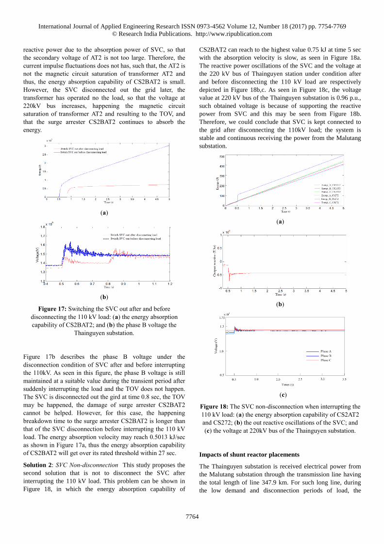
International Journal of Applied Engineering Research ISSN 0973-4562 Volume 12, Number 18 (2017) pp. 7754-7769
© Research India Publications. http://www.ripublication.com
7764
reactive power due to the absorption power of SVC, so that
the secondary voltage of AT2 is not too large. Therefore, the
current impulse fluctuations does not has, such that, the AT2 is
not the magnetic circuit saturation of transformer AT2 and
thus, the energy absorption capability of CS2BAT2 is small.
However, the SVC disconnected out the grid later, the
transformer has operated no the load, so that the voltage at
220kV bus increases, happening the magnetic circuit
saturation of transformer AT2 and resulting to the TOV, and
that the surge arrester CS2BAT2 continues to absorb the
energy.
(a)
(b)
Figure 17: Switching the SVC out after and before
disconnecting the 110 kV load: (a) the energy absorption
capability of CS2BAT2; and (b) the phase B voltage the
Thainguyen substation.
Figure 17b describes the phase B voltage under the
disconnection condition of SVC after and before interrupting
the 110kV. As seen in this figure, the phase B voltage is still
maintained at a suitable value during the transient period after
suddenly interrupting the load and the TOV does not happen.
The SVC is disconnected out the gird at time 0.8 sec, the TOV
may be happened, the damage of surge arrester CS2BAT2
cannot be helped. However, for this case, the happening
breakdown time to the surge arrester CS2BAT2 is longer than
that of the SVC disconnection before interrupting the 110 kV
load. The energy absorption velocity may reach 0.5013 kJ/sec
as shown in Figure 17a, thus the energy absorption capability
of CS2BAT2 will get over its rated threshold within 27 sec.
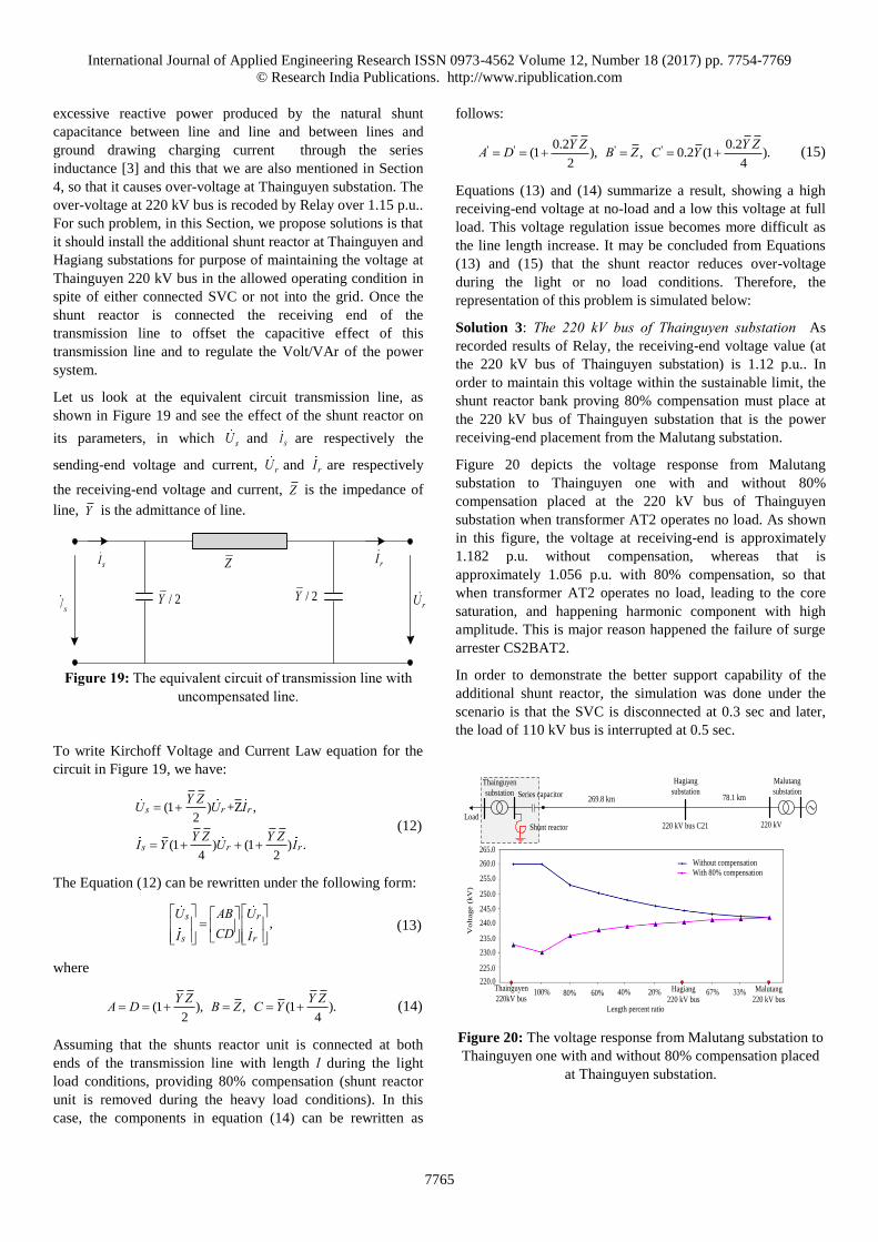
Solution 2: SVC Non-disconnection This study proposes the
second solution that is not to disconnect the SVC after
interrupting the 110 kV load. This problem can be shown in
Figure 18, in which the energy absorption capability of
CS2BAT2 can reach to the highest value 0.75 kJ at time 5 sec
with the absorption velocity is slow, as seen in Figure 18a.
The reactive power oscillations of the SVC and the voltage at
the 220 kV bus of Thainguyen station under condition after
and before disconnecting the 110 kV load are respectively
depicted in Figure 18b,c. As seen in Figure 18c, the voltage
value at 220 kV bus of the Thainguyen substation is 0.96 p.u.,
such obtained voltage is because of supporting the reactive
power from SVC and this may be seen from Figure 18b.
Therefore, we could conclude that SVC is kept connected to
the grid after disconnecting the 110kV load; the system is
stable and continuous receiving the power from the Malutang
substation.
(a)
(b)
(c)
Figure 18: The SVC non-disconnection when interrupting the
110 kV load: (a) the energy absorption capability of CS2AT2
and CS272; (b) the out reactive oscillations of the SVC; and
(c) the voltage at 220kV bus of the Thainguyen substation.
Impacts of shunt reactor placements
The Thainguyen substation is received electrical power from
the Malutang substation through the transmission line having
the total length of line 347.9 km. For such long line, during
the low demand and disconnection periods of load, the
International Journal of Applied Engineering Research ISSN 0973-4562 Volume 12, Number 18 (2017) pp. 7754-7769
© Research India Publications. http://www.ripublication.com
7765
excessive reactive power produced by the natural shunt
capacitance between line and line and between lines and
ground drawing charging current through the series
inductance [3] and this that we are also mentioned in Section
4, so that it causes over-voltage at Thainguyen substation. The
over-voltage at 220 kV bus is recoded by Relay over 1.15 p.u..
For such problem, in this Section, we propose solutions is that
it should install the additional shunt reactor at Thainguyen and
Hagiang substations for purpose of maintaining the voltage at
Thainguyen 220 kV bus in the allowed operating condition in
spite of either connected SVC or not into the grid. Once the
shunt reactor is connected the receiving end of the
transmission line to offset the capacitive effect of this
transmission line and to regulate the Volt/VAr of the power
system.
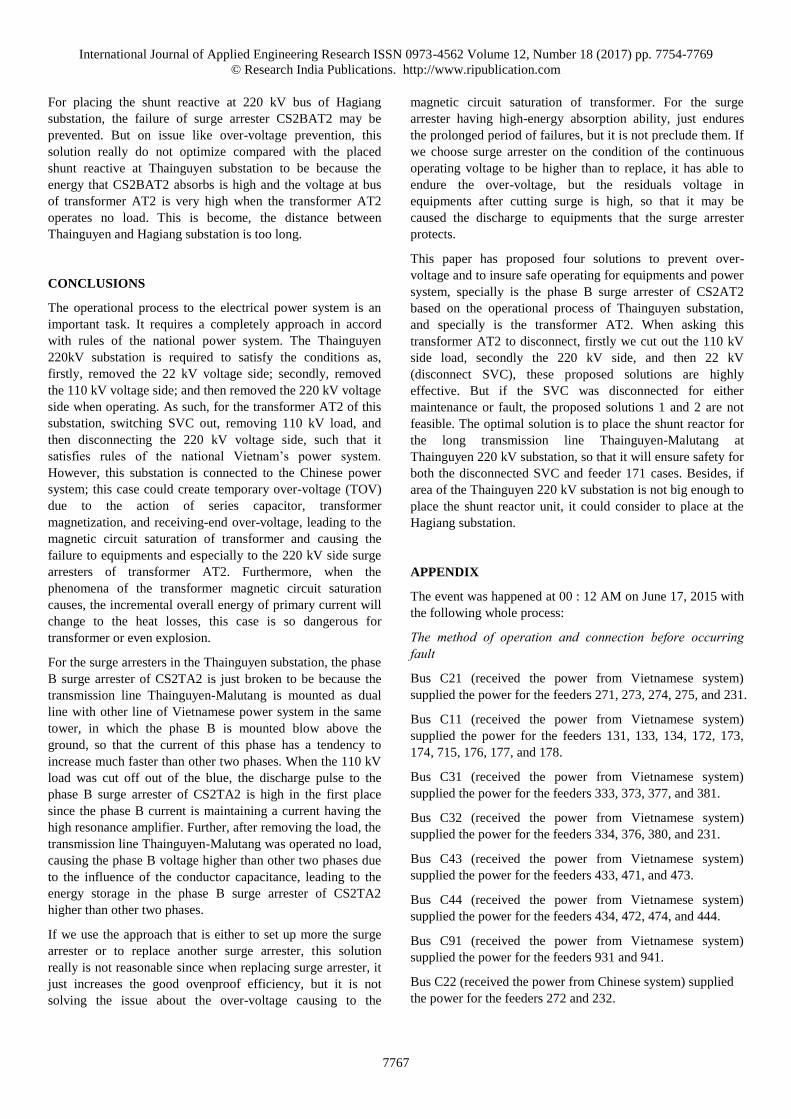
Let us look at the equivalent circuit transmission line, as
shown in Figure 19 and see the effect of the shunt reactor on
its parameters, in which sU and sI are respectively the
sending-end voltage and current, rU and rI are respectively
the receiving-end voltage and current, Z is the impedance of
line, Y is the admittance of line.
sU
sI Z
/ 2Y / 2YrU
rI
Figure 19: The equivalent circuit of transmission line with
uncompensated line.
To write Kirchoff Voltage and Current Law equation for the
circuit in Figure 19, we have:
(1 ) +Z ,2
(1 ) (1 ) .4 2
s r r
s r r
Y ZU U I
Y Z Y ZI Y U I
(12)
The Equation (12) can be rewritten under the following form:
,s r
s r
U AB UCDI I
(13)
where
(1 ), , (1 ).2 4
Y Z Y ZA D B Z C Y (14)
Assuming that the shunts reactor unit is connected at both
ends of the transmission line with length l during the light
load conditions, providing 80% compensation (shunt reactor
unit is removed during the heavy load conditions). In this
case, the components in equation (14) can be rewritten as
follows:
' ' ' '0.2 0.2(1 ), , 0.2 (1 ).
2 4
Y Z Y ZA D B Z C Y (15)
Equations (13) and (14) summarize a result, showing a high
receiving-end voltage at no-load and a low this voltage at full
load. This voltage regulation issue becomes more difficult as
the line length increase. It may be concluded from Equations
(13) and (15) that the shunt reactor reduces over-voltage
during the light or no load conditions. Therefore, the
representation of this problem is simulated below:
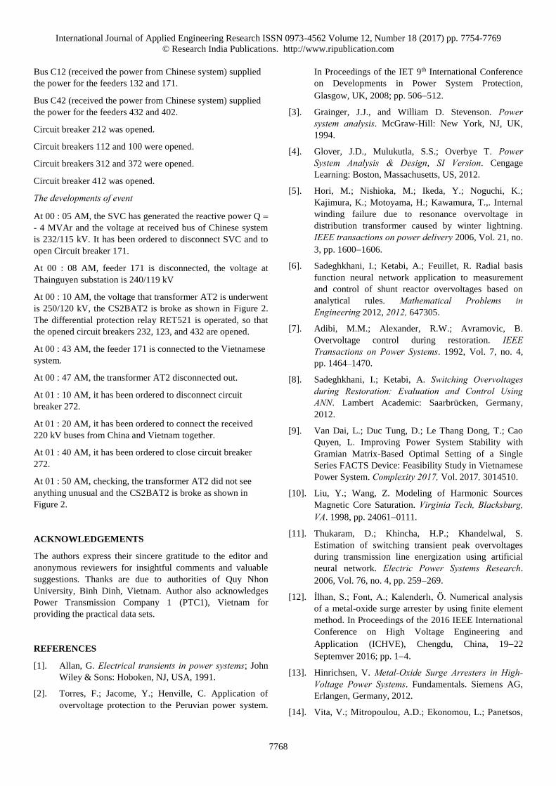
Solution 3: The 220 kV bus of Thainguyen substation As
recorded results of Relay, the receiving-end voltage value (at
the 220 kV bus of Thainguyen substation) is 1.12 p.u.. In
order to maintain this voltage within the sustainable limit, the
shunt reactor bank proving 80% compensation must place at
the 220 kV bus of Thainguyen substation that is the power
receiving-end placement from the Malutang substation.
Figure 20 depicts the voltage response from Malutang
substation to Thainguyen one with and without 80%
compensation placed at the 220 kV bus of Thainguyen
substation when transformer AT2 operates no load. As shown
in this figure, the voltage at receiving-end is approximately
1.182 p.u. without compensation, whereas that is
approximately 1.056 p.u. with 80% compensation, so that
when transformer AT2 operates no load, leading to the core
saturation, and happening harmonic component with high
amplitude. This is major reason happened the failure of surge
arrester CS2BAT2.
In order to demonstrate the better support capability of the
additional shunt reactor, the simulation was done under the
scenario is that the SVC is disconnected at 0.3 sec and later,
the load of 110 kV bus is interrupted at 0.5 sec.
Series capacitor
Thainguyen
substation
Malutang
substation
Shunt reactor
220.0
230.0
235.0
240.0
245.0
250.0
255.0
265.0
Volt
age (
kV
)
Without compensationWith 80% compensation
Malutang
220 kV bus
Thainguyen
220kV bus100% 60% 40% 20% Hagiang
220 kV bus67% 33%
Length percent ratio
269.8 km
Hagiang
substation78.1 km
220 kV220 kV bus C21
80%
225.0
260.0
~
Load
Figure 20: The voltage response from Malutang substation to
Thainguyen one with and without 80% compensation placed
at Thainguyen substation.

International Journal of Applied Engineering Research ISSN 0973-4562 Volume 12, Number 18 (2017) pp. 7754-7769
© Research India Publications. http://www.ripublication.com
7766
Figure 21 is a plot of the voltage at the 220kV bus of the
Thainguyen substation and the energy absorption capability of
the surge arresters CS2AT2 and CS272. As obtained result
from Figure 21a, when shunt reactor connected at the 220 kV
bus of Thainguyen substation, during operational process, the
voltage at the 220kV bus is approximately 1.05 p.u.. For such
voltage value, the magnetic circuit saturation phenomenon of
AT2 does not occur. As a result, the energy absorption
capability of CS2BAT2 is slow, in particular, after switching
the 110 kV load out, the maximum energy that CS2BAT2
drawn is approximately 16.5 kJ at 0.75 sec, as seen in Figure
21b.
(a)
(b)
Figure 21: The shunt reactor placed at 220 kV Thainguyen
substation: (a) The voltage at the 220kV bus; and (b) The
energy absorption capability of CS2AT2 and CS272.
Solution 4: The 220 kV bus of Hagiang substation The fact
that, we want to build the shunt reactor system need to have a
large area. However, the area at the Thainguyen substation is
enough large to place the shun reactor system. The Malutang-
Thainguyen transmission line is indirectly connected thought
the 220 kV Hagiang substation, the distance from this
substation to Thainguyen one is 269.8 km, as shown in Figure
6 and thanks to it, we propose the fourth solution is that the
shunt reactor bank proving 80% compensation placed at the
220 kV bus of Hagiang substation.
Figure 22 depicts the voltage response from Malutang
substation to Thainguyen one with and without 80%
compensation placed at the 220 kV bus C21 of Hagiang
substation when transformer AT2 operates no load. As seen in
this figure, the voltage at receiving-end is approximately 1.19
p.u. without compensation, whereas that is approximately 1.12
p.u. with 80% compensation, so that when transformer AT2
operates no load, leading to the core saturation and creating
harmonic component with high amplitude. This is major
reason caused the failure of surge arrester CS2BAT2.
Series capacitor
220.0
230.0
235.0
240.0
245.0
250.0
255.0
265.0
Vo
ltag
e (
kV
)
Without compensation
With 80% compensation
Malutang
220kV bus
Thainguyen
220kV bus100% 60% 40% 20% Hagiang
220kV bus67% 33%
Length percent ratio
269.8 km
Hagiang
substation78.1 km
220 kV
220 kV bus C21
80%
225.0
260.0
Shunt reactor220 kV bus~
Thainguyen
substation
Load
Malutang
substation
Figure 22: The voltage response from Malutang substation to
Thainguyen one with and without 80% compensation placed
at Hagiang substation.
In order to demonstrate the better support capability of the
additional shunt reactor placed at 220 kV bus C21 of Hagiang,
the simulation was done under the scenario is that the SVC is
removed at 0.3 sec and later, the load of 110 kV bus is
removed at 0.5 sec.
Figure 23 is a plot of the voltage at the 220kV bus of the
Thainguyen substation and the energy absorption capability of
the surge arresters CS2AT2. As can be seen Figure 23b, when
shunt reactor is connected, the CS2TA2 absorbs the energy
reduced greatly in the process of operation and after removing
the 110 kV load, the phase B of surge arrester CS2AT2
absorbs with the maximum energy 93.25 kJ at 1.05 sec.
(a)
(b)
Figure 23: Placing the shun reactor at 220 kV Hagiang
substation: (a) The voltage at the 220kV bus; and (b) the
energy absorption capability of CS2AT2.
International Journal of Applied Engineering Research ISSN 0973-4562 Volume 12, Number 18 (2017) pp. 7754-7769
© Research India Publications. http://www.ripublication.com
7767
For placing the shunt reactive at 220 kV bus of Hagiang
substation, the failure of surge arrester CS2BAT2 may be
prevented. But on issue like over-voltage prevention, this
solution really do not optimize compared with the placed
shunt reactive at Thainguyen substation to be because the
energy that CS2BAT2 absorbs is high and the voltage at bus
of transformer AT2 is very high when the transformer AT2
operates no load. This is become, the distance between
Thainguyen and Hagiang substation is too long.
CONCLUSIONS
The operational process to the electrical power system is an
important task. It requires a completely approach in accord
with rules of the national power system. The Thainguyen
220kV substation is required to satisfy the conditions as,
firstly, removed the 22 kV voltage side; secondly, removed
the 110 kV voltage side; and then removed the 220 kV voltage
side when operating. As such, for the transformer AT2 of this
substation, switching SVC out, removing 110 kV load, and
then disconnecting the 220 kV voltage side, such that it
satisfies rules of the national Vietnam’s power system.
However, this substation is connected to the Chinese power
system; this case could create temporary over-voltage (TOV)
due to the action of series capacitor, transformer
magnetization, and receiving-end over-voltage, leading to the
magnetic circuit saturation of transformer and causing the
failure to equipments and especially to the 220 kV side surge
arresters of transformer AT2. Furthermore, when the
phenomena of the transformer magnetic circuit saturation
causes, the incremental overall energy of primary current will
change to the heat losses, this case is so dangerous for
transformer or even explosion.
For the surge arresters in the Thainguyen substation, the phase
B surge arrester of CS2TA2 is just broken to be because the
transmission line Thainguyen-Malutang is mounted as dual
line with other line of Vietnamese power system in the same
tower, in which the phase B is mounted blow above the
ground, so that the current of this phase has a tendency to
increase much faster than other two phases. When the 110 kV
load was cut off out of the blue, the discharge pulse to the
phase B surge arrester of CS2TA2 is high in the first place
since the phase B current is maintaining a current having the
high resonance amplifier. Further, after removing the load, the
transmission line Thainguyen-Malutang was operated no load,
causing the phase B voltage higher than other two phases due
to the influence of the conductor capacitance, leading to the
energy storage in the phase B surge arrester of CS2TA2
higher than other two phases.
If we use the approach that is either to set up more the surge
arrester or to replace another surge arrester, this solution
really is not reasonable since when replacing surge arrester, it
just increases the good ovenproof efficiency, but it is not
solving the issue about the over-voltage causing to the
magnetic circuit saturation of transformer. For the surge
arrester having high-energy absorption ability, just endures
the prolonged period of failures, but it is not preclude them. If
we choose surge arrester on the condition of the continuous
operating voltage to be higher than to replace, it has able to
endure the over-voltage, but the residuals voltage in
equipments after cutting surge is high, so that it may be
caused the discharge to equipments that the surge arrester
protects.
This paper has proposed four solutions to prevent over-
voltage and to insure safe operating for equipments and power
system, specially is the phase B surge arrester of CS2AT2
based on the operational process of Thainguyen substation,
and specially is the transformer AT2. When asking this
transformer AT2 to disconnect, firstly we cut out the 110 kV
side load, secondly the 220 kV side, and then 22 kV
(disconnect SVC), these proposed solutions are highly
effective. But if the SVC was disconnected for either
maintenance or fault, the proposed solutions 1 and 2 are not
feasible. The optimal solution is to place the shunt reactor for
the long transmission line Thainguyen-Malutang at
Thainguyen 220 kV substation, so that it will ensure safety for
both the disconnected SVC and feeder 171 cases. Besides, if
area of the Thainguyen 220 kV substation is not big enough to
place the shunt reactor unit, it could consider to place at the
Hagiang substation.
APPENDIX
The event was happened at 00 : 12 AM on June 17, 2015 with
the following whole process:
The method of operation and connection before occurring fault
Bus C21 (received the power from Vietnamese system)
supplied the power for the feeders 271, 273, 274, 275, and 231.
Bus C11 (received the power from Vietnamese system)
supplied the power for the feeders 131, 133, 134, 172, 173,
174, 715, 176, 177, and 178.
Bus C31 (received the power from Vietnamese system)
supplied the power for the feeders 333, 373, 377, and 381.
Bus C32 (received the power from Vietnamese system)
supplied the power for the feeders 334, 376, 380, and 231.
Bus C43 (received the power from Vietnamese system)
supplied the power for the feeders 433, 471, and 473.
Bus C44 (received the power from Vietnamese system)
supplied the power for the feeders 434, 472, 474, and 444.
Bus C91 (received the power from Vietnamese system)
supplied the power for the feeders 931 and 941.
Bus C22 (received the power from Chinese system) supplied
the power for the feeders 272 and 232.
International Journal of Applied Engineering Research ISSN 0973-4562 Volume 12, Number 18 (2017) pp. 7754-7769
© Research India Publications. http://www.ripublication.com
7768
Bus C12 (received the power from Chinese system) supplied
the power for the feeders 132 and 171.
Bus C42 (received the power from Chinese system) supplied
the power for the feeders 432 and 402.
Circuit breaker 212 was opened.
Circuit breakers 112 and 100 were opened.
Circuit breakers 312 and 372 were opened.
Circuit breaker 412 was opened.
The developments of event
At 00 : 05 AM, the SVC has generated the reactive power Q
- 4 MVAr and the voltage at received bus of Chinese system
is 232/115 kV. It has been ordered to disconnect SVC and to
open Circuit breaker 171.
At 00 : 08 AM, feeder 171 is disconnected, the voltage at
Thainguyen substation is 240/119 kV
At 00 : 10 AM, the voltage that transformer AT2 is underwent
is 250/120 kV, the CS2BAT2 is broke as shown in Figure 2.
The differential protection relay RET521 is operated, so that
the opened circuit breakers 232, 123, and 432 are opened.
At 00 : 43 AM, the feeder 171 is connected to the Vietnamese
system.
At 00 : 47 AM, the transformer AT2 disconnected out.
At 01 : 10 AM, it has been ordered to disconnect circuit
breaker 272.
At 01 : 20 AM, it has been ordered to connect the received
220 kV buses from China and Vietnam together.
At 01 : 40 AM, it has been ordered to close circuit breaker
272.
At 01 : 50 AM, checking, the transformer AT2 did not see
anything unusual and the CS2BAT2 is broke as shown in
Figure 2.
ACKNOWLEDGEMENTS
The authors express their sincere gratitude to the editor and
anonymous reviewers for insightful comments and valuable
suggestions. Thanks are due to authorities of Quy Nhon
University, Binh Dinh, Vietnam. Author also acknowledges
Power Transmission Company 1 (PTC1), Vietnam for
providing the practical data sets.
REFERENCES
[1]. Allan, G. Electrical transients in power systems; John
Wiley & Sons: Hoboken, NJ, USA, 1991.
[2]. Torres, F.; Jacome, Y.; Henville, C. Application of
overvoltage protection to the Peruvian power system.
In Proceedings of the IET 9th International Conference
on Developments in Power System Protection,
Glasgow, UK, 2008; pp. 506512.
[3]. Grainger, J.J., and William D. Stevenson. Power system analysis. McGraw-Hill: New York, NJ, UK,
1994.
[4]. Glover, J.D., Mulukutla, S.S.; Overbye T. Power System Analysis & Design, SI Version. Cengage
Learning: Boston, Massachusetts, US, 2012.
[5]. Hori, M.; Nishioka, M.; Ikeda, Y.; Noguchi, K.;
Kajimura, K.; Motoyama, H.; Kawamura, T.,. Internal
winding failure due to resonance overvoltage in
distribution transformer caused by winter lightning.
IEEE transactions on power delivery 2006, Vol. 21, no.
3, pp. 16001606.
[6]. Sadeghkhani, I.; Ketabi, A.; Feuillet, R. Radial basis
function neural network application to measurement
and control of shunt reactor overvoltages based on
analytical rules. Mathematical Problems in Engineering 2012, 2012, 647305.
[7]. Adibi, M.M.; Alexander, R.W.; Avramovic, B.
Overvoltage control during restoration. IEEE Transactions on Power Systems. 1992, Vol. 7, no. 4,
pp. 1464–1470.
[8]. Sadeghkhani, I.; Ketabi, A. Switching Overvoltages during Restoration: Evaluation and Control Using ANN. Lambert Academic: Saarbrücken, Germany,
2012.
[9]. Van Dai, L.; Duc Tung, D.; Le Thang Dong, T.; Cao
Quyen, L. Improving Power System Stability with
Gramian Matrix-Based Optimal Setting of a Single
Series FACTS Device: Feasibility Study in Vietnamese
Power System. Complexity 2017, Vol. 2017, 3014510.
[10]. Liu, Y.; Wang, Z. Modeling of Harmonic Sources
Magnetic Core Saturation. Virginia Tech, Blacksburg, VA. 1998, pp. 240610111.
[11]. Thukaram, D.; Khincha, H.P.; Khandelwal, S.
Estimation of switching transient peak overvoltages
during transmission line energization using artificial
neural network. Electric Power Systems Research.
2006, Vol. 76, no. 4, pp. 259269.
[12]. İlhan, S.; Font, A.; Kalenderlı, Ö. Numerical analysis
of a metal-oxide surge arrester by using finite element
method. In Proceedings of the 2016 IEEE International
Conference on High Voltage Engineering and
Application (ICHVE), Chengdu, China, 1922
Septemver 2016; pp. 14.
[13]. Hinrichsen, V. Metal-Oxide Surge Arresters in High-Voltage Power Systems. Fundamentals. Siemens AG,
Erlangen, Germany, 2012.
[14]. Vita, V.; Mitropoulou, A.D.; Ekonomou, L.; Panetsos,

International Journal of Applied Engineering Research ISSN 0973-4562 Volume 12, Number 18 (2017) pp. 7754-7769
© Research India Publications. http://www.ripublication.com
7769
S.; Stathopulos, I.A. Comparison of metal-oxide surge
arresters circuit models and implementation on high-
voltage transmission lines of the Hellenic network. IET generation, transmission & distribution 2010, Vol. 4,
no. 7, pp. 846853.
[15]. Bayadi, A. Parameter identification of ZnO surge
arrester models based on genetic algorithms. Electric Power Systems Research 2008, vol. 78, no.7, pp.
12041209.
[16]. Nafar, M., Gharehpetian, G.B.; Niknam, T.
Improvement of estimation of surge arrester parameters
by using modified particle swarm optimization. Energy 2011, vol. 36, no.8, pp. 48484854.
[17]. High voltage surge arresters buyer’s guide-section
PEXLIM Q: Availabe online: http://new.abb.com/high
voltage/surge -arresters (accessed on 5 September
2014).
[18]. Arrester V-I characteristics tool AF003.1. Available
online: http://www.arresterworks.com (accessed on 20
July 2011).
[19]. Van Dai, L.; Li, X.; Li, P.; Quyen, L.C. An optimal
location of static VAr compensator based on Gramian
critical energy for damping oscillations in power
systems. IEEJ Transactions on Electrical and Electronic Engineering 2016, vol. 11, no. 5, pp.
577585.
[20]. Song, Y.H.; Johns, A. Flexible ac transmission systems (FACTS). IET London: London, UK, 1999.
[21]. Slegers, J. Transmission line loading sag calculations
and high-temperature conductor technologies.
Available online: http://home.eng.iastate.edu/~jdm
/wind/TransmissionLineLoadingDesignCriteriaAndH
TS.pdf (accessed on 18 October 2011).
[22]. Hase, Y. Handbook of power system engineering. John
Wiley & Sons: Hoboken, NJ, USA, 2007.
[23]. Saadat, Hadi. Power system analysis. McGraw-Hill :
New York, NJ, UK, 1999.
[24]. Weedy, B.M., Cory, B.J., Jenkins, N., Ekanayake, J.B.
and Strbac, G. Electric power systems. John Wiley &
Sons: Hoboken, NJ, USA, 2012.
[25]. Grigsby, L.L. Electric power generation, transmission, and distribution. CRC press: Boca Raton, Florida. US,
2012.
[26]. Kersting, W.H. Distribution system modeling and analysis. CRC press: Boca Raton, Florida. US, 2012.
[27]. Eremia, M.; Liu, C.C.; Edris, A.A. Advanced Solutions in Power Systems: HVDC, FACTS, and Artificial Intelligence. John Wiley & Sons: Hoboken, NJ, USA,
2016.