overall architectural framework -...
TRANSCRIPT

D3.1 – Overall Architectural Framework Rev. 2.2
AMADEOS - Architecture for Multi-criticality Agile Dependable Evolutionary Open System-of-Systems Page 1 of 66
FP7-ICT-2013.3.4
Project acronym: AMADEOS
Project full title: Architecture for Multi-criticality Agile Dependable Evolutionary Open System-of-Systems
Grant Agreement no.: 610535
Partners:
[1] Università degli Studi di Firenze
[2] Technische Universitaet Wien
[3] Universite Joseph Fourier Grenoble 1
[4] ResilTech S.r.l.
[5] Thales Nederland Bv
[6] European Network For Cyber Security Cooperatief Ua
D3.1 – OVERALL ARCHITECTURAL FRAMEWORK
(01.07.2014-31.03.2015)
Revision of the document: 2.2
Responsible partner: TNL
Contributing partner(s): all
Reviewing partner(s): UJF, RES
Document date: 13/04/2015
Dissemination level: RE
© Copyright 2014 AMADEOS Project. All rights reserved
This document and its contents are the property of AMADEOS Partners. All rights relevant to this document are determined by the applicable laws. This document is furnished on the following conditions: no right or license in respect to this document or its content is given or waived in supplying this document to you. This document or its contents are not be used or treated in any manner inconsistent with the rights or interests of AMADEOS Partners or to its detriment and are not be disclosed to others without prior written consent from AMADEOS Partners. Each AMADEOS Partners may use this document according to AMADEOS Consortium Agreement.

D3.1 – Overall Architectural Framework Rev. 2.2
AMADEOS - Architecture for Multi-criticality Agile Dependable Evolutionary Open System-of-Systems Page 2 of 66
Change Records
Revision Date Changes Authors Status1
0.1 30/07/2014 Initial Table of Contents. TNL NV
0.2 27/09/2014 Initial version after UNIFI, TUW comments. TNL/UNIFI/TUW NV
0.3 9/10/2014 First draft, prior to Pontedera meeting. ALL NV
0.4 27/11/2014 Second draft, prior to December deadline. TNL/UNIFI/ENCS NV
0.5 13/12/2014 Third draft, prior to December deadline. ALL NV
0.6 18/12/2014 December version, ready for Advisory Board (only sections 2 and 3 at this stage).
ALL NV
0.7 05/02/2015 (Near) completion of Sections 2 & 3, initial framework for Section 4.
TNL/TUW/ENCS NV
0.8 10/02/2015 Updates to Sections 2 & 3. UJF NV
0.9 17/02/2015 Updates to Section 4. Integrated inputs. TNL/TUW/UNIFI NV
1.0 18/02/2015 Updates to Sections 3.4 and 4.2. RES/UNIFI NV
1.1 22/02/2015 Structure of Section 4 modified. UNIFI/TNL NV
1.2 27/02/2015 Initial versions of Section 1 & 5. Section 4 contributions integrated. Draft for initial review.
ALL NV
1.3 12/03/2015 Updated version based on internal review and additions from partners.
TNL/UJF/RES/UNIFI NV
1.4 17/03/2015 Updates from all partners to address comments. ALL NV
1.5 18/03/2015 Updates from UJF, TNL. Finished addressing comments.
UJF/TNL NV
1.6 24/03/2015 Modifications to the initial subsections of Section 4.
UNIFI NV
2.0 27/03/2015 Merging of contributions to Section 4; version ready for second review round.
TNL/UJF/ENCS/RES/
UNIFI NV
2.1 07/04/2015 Version revised according to minor comments from internal reviewers (second-review round).
UNIFI NV
2.2 13/04/2015 Final version addressing last remaining reviewers’ comments, ready for submission.
TNL, UNIFI V
1 V - Valid, NV - Not Valid, R - Revision

D3.1 – Overall Architectural Framework Rev. 2.2
AMADEOS - Architecture for Multi-criticality Agile Dependable Evolutionary Open System-of-Systems Page 3 of 66
TABLE OF CONTENTS
1 INTRODUCTION .................................................................................................................... 12
2 CURRENT VIEW ON EVOLVABLE SOS ARCHITECTURES ............................................... 13
2.1 Consensus on SoS Architectural Frameworks ............................................................... 13
2.1.1 What is an architectural framework? .......................................................................... 13
2.1.2 Why do people need architectural frameworks? ......................................................... 14
2.1.3 What are prerequisites and/or properties of architectural frameworks? ...................... 14
2.1.4 What are ingredients of architectural frameworks? ..................................................... 16
2.1.5 Evolvability in architectural framworks ........................................................................ 16
2.1.6 Different views on architectural frameworks ............................................................... 17
2.2 Architectural Frameworks currently in use ...................................................................... 18
2.2.1 Military frameworks (DoDAF, MODAF, IDEAS) .......................................................... 18
2.2.2 TOGAF....................................................................................................................... 18
2.2.3 Zachman + extension ................................................................................................. 20
2.2.4 Cafall&Michael ........................................................................................................... 21
2.2.5 Monatagna & Mahmood ............................................................................................. 22
2.2.6 Archimate ................................................................................................................... 22
2.2.7 PPOOA ...................................................................................................................... 22
2.3 ADLs in SoS Architectural Frameworks .......................................................................... 23
2.4 Major concerns in designing an AMADEOS Architectural Framework ............................ 24
3 BUILDING BLOCKS .............................................................................................................. 26
3.1 SoS Management Infrastructure ..................................................................................... 26
3.1.1 Formal Hierarchy ........................................................................................................ 27
3.1.2 Non-formal hierarchy .................................................................................................. 28
3.1.3 Patterns composition .................................................................................................. 29
3.1.4 Infrastructure communication ..................................................................................... 30
3.1.5 Quality of Service and SLA management ................................................................... 30
3.2 Relied Upon Interfaces ................................................................................................... 31
3.2.1 The Relied Upon Interface Models ............................................................................. 32
3.2.2 Quality of Service and Service Level Agreement (SLA) .............................................. 32
3.2.3 Request Reply Model of the RUMI ............................................................................. 32
3.2.4 Example: Smart Grid .................................................................................................. 32
3.3 Towards a Time-Aware System-of-Systems Architecture ............................................... 34
3.3.1 Resilient Master Clock ................................................................................................ 36
3.4 Dependability aspects .................................................................................................... 37
3.4.1 Multi-level security for Systems-of-Systems ............................................................... 37
3.4.2 Trust and Trustworthiness .......................................................................................... 39

D3.1 – Overall Architectural Framework Rev. 2.2
AMADEOS - Architecture for Multi-criticality Agile Dependable Evolutionary Open System-of-Systems Page 4 of 66
3.4.3 Safety and Reliability .................................................................................................. 39
3.4.4 Legacy System Integration ......................................................................................... 40
3.5 Evolutionary aspects ...................................................................................................... 40
3.5.1 Scenario-based Reasoning for SoS Architecture design ............................................ 40
4 AMADEOS ARCHITECTURAL FRAMEWORK ..................................................................... 42
4.1 High-level view ............................................................................................................... 42
4.2 Viewpoint-driven Analysis .............................................................................................. 45
4.2.1 Motivating Scenario .................................................................................................... 45
4.3 Viewpoint of Structure .................................................................................................... 46
4.3.1 Conceptual Level ....................................................................................................... 46
4.3.2 Logical Level .............................................................................................................. 47
4.3.3 Implementation level .................................................................................................. 48
4.3.4 Use case instance ...................................................................................................... 48
4.4 Viewpoint of Dynamicity ................................................................................................. 48
4.4.1 Conceptual Level ....................................................................................................... 48
4.4.2 Logical Level .............................................................................................................. 49
4.4.3 Implementation level .................................................................................................. 49
4.4.4 Use case instance ...................................................................................................... 49
4.5 Viewpoint of Evolution .................................................................................................... 50
4.5.1 Conceptual Level ....................................................................................................... 50
4.5.2 Logical Level .............................................................................................................. 51
4.5.3 Implementation level .................................................................................................. 51
4.5.4 Use case instance ...................................................................................................... 51
4.6 Viewpoint of Dependability and Security ........................................................................ 52
4.6.1 Conceptual Level ....................................................................................................... 52
4.6.2 Logical Level .............................................................................................................. 52
4.6.3 Implementation level .................................................................................................. 53
4.6.4 Use Case Instance ..................................................................................................... 53
4.7 Viewpoint of Time .......................................................................................................... 54
4.7.1 Conceptual Level ....................................................................................................... 54
4.7.2 Logical Level .............................................................................................................. 55
4.7.3 Implementation level .................................................................................................. 55
4.7.4 Use case instance ...................................................................................................... 56
4.8 Viewpoint of Multi-criticality ............................................................................................ 56
4.8.1 Conceptual Level ....................................................................................................... 56
4.8.2 Logical Level .............................................................................................................. 57
4.8.3 Implementation Level ................................................................................................. 58
4.8.4 Use case instance ...................................................................................................... 58

D3.1 – Overall Architectural Framework Rev. 2.2
AMADEOS - Architecture for Multi-criticality Agile Dependable Evolutionary Open System-of-Systems Page 5 of 66
4.9 Viewpoint of Emergence ................................................................................................ 59
4.9.1 Conceptual Level ....................................................................................................... 59
4.9.2 Logical Level .............................................................................................................. 60
4.9.3 Implementation level .................................................................................................. 61
4.9.4 Use case instance ...................................................................................................... 61
4.10 Discussion ..................................................................................................................... 62
5 CONCLUSIONS ..................................................................................................................... 63
6 BIBLIOGRAPHY .................................................................................................................... 64

D3.1 – Overall Architectural Framework Rev. 2.2
AMADEOS - Architecture for Multi-criticality Agile Dependable Evolutionary Open System-of-Systems Page 6 of 66
LIST OF FIGURES
Figure 1 - The TOGAF ADM Lifecycle Model................................................................................. 19
Figure 2 - MAPE-K control loop ..................................................................................................... 26
Figure 3 - Hierarchical control pattern ............................................................................................ 27
Figure 4 - Master/Slave pattern ..................................................................................................... 28
Figure 5 - Regional planner pattern ............................................................................................... 28
Figure 6 - Coordinated control pattern ........................................................................................... 29
Figure 7 - Information sharing pattern ............................................................................................ 29
Figure 8 - Atomic pattern ............................................................................................................... 30
Figure 9 - Positioning of SLA in MAPE Cycle................................................................................. 30
Figure 10 - Interfaces between two CSs. ....................................................................................... 31
Figure 11 - RUI of Smart Grid example. ......................................................................................... 33
Figure 12 - A small example causal model for SBR. ...................................................................... 41
Figure 13 - AMADEOS Architectural Framework. .......................................................................... 42
Figure 14 - Refinement and evolution of processes in Architectural Framework Design ................ 44

D3.1 – Overall Architectural Framework Rev. 2.2
AMADEOS - Architecture for Multi-criticality Agile Dependable Evolutionary Open System-of-Systems Page 7 of 66
LIST OF TABLES
Table 1 Original ISA Table (from [3]) with Examples in each cell. .................................................. 20
Table 2 Additional Columns defined in EISA (from [3]) .................................................................. 21

D3.1 – Overall Architectural Framework Rev. 2.2
AMADEOS - Architecture for Multi-criticality Agile Dependable Evolutionary Open System-of-Systems Page 8 of 66
Definitions and Acronyms
Acronym Definition
ACROSS ARTEMIS CROSS-Domain Architecture
ADL Architectural Description Language
ADM Architecture Description Model
ASFiNAG Autobahnen und Schnellstraßen-Finanzierungs-Aktiengesellschaft
CARTS Computer Aided architectural analysis of Real-Time Systems. FP5-IST Project (2000 - 2002) http://cordis.europa.eu/project/rcn/53615_en.html
BAPO Business, Architecture, Processes and Organization
BDD Block Definition Diagram
CASE Computer-aided software engineering
CDF Concurrent Design Facility
CML COMPASS modelling language
COMPASS Comprehensive Modelling for Advanced Systems of Systems. EU FP7 IST Project http://www.compass-research.eu
COTS Commercial off the shelf
CSO Charging Station Operator
DANSE Designing for Adaptability and Evolution in Systems of Systems Engineering. EU FP7 ICT Project http://www.danse-ip.eu
DER Distributed Energy Resources
DODAF Department of Defence Architectural Framework
DSO Distribution System Operator
DSRC Dedicated Short Range Communication
ECR Error Containment Region
ECU Electronic Control Unit
EISA Extended Information Systems Architecture

D3.1 – Overall Architectural Framework Rev. 2.2
AMADEOS - Architecture for Multi-criticality Agile Dependable Evolutionary Open System-of-Systems Page 9 of 66
ESA European Space Agency
FCR Fault Containment Region
GNSS Global Navigation Satellite System
GPS Global Positioning System
IDEAS International Defence Enterprise Architecture Specification
IEEE Institute of Electrical and Electronic Engineers
ISA Information Systems Architecture
ISO/IEC International Organization for Standardization/ International Electrotechnical Commission
IST Information Society Technologies
LIF Linking Interface
LMO Load Management Optimizer
LOCC Landlijk Operantioneel Crisis Centrum (Dutch National Operational Crisis Centre)
MAPE Monitoring, Analyze, Plan and Execution Architecture
MDSD Model-Driven Systems Development
MILS Multiple Independent Levels of Security
MLS Multi level Security
MOD Ministry of Defence (UK)
MODAF Ministry of Defence Architectural Framework
MRI Magnetic Resonance Imaging
MSLS Multiple Single-Level Secure
MVGC Medium Voltage Grid Controller
NAF NATO Architectural Framework
NATO North Atlantic Treaty Organisation
NEC Network Enabled Capabilities
OPTET OPerational Trustworthiness Enabling Technologies: A EU FP7 Project.

D3.1 – Overall Architectural Framework Rev. 2.2
AMADEOS - Architecture for Multi-criticality Agile Dependable Evolutionary Open System-of-Systems Page 10 of 66
PPOOA Processes Pipelines in Object Oriented Architectures
RSU Road Side Units
RUI Relied-upon Interface
RUMI Relied-upon Message Interface
RUPI Relied-upon Physical Interface
SBR Scenario Based Reasoning
SEI Software Engineering Institute at Carnegie Mellon University
SLA Service Level Agreement
SLS Single-Level Secure
SOTA State of the Art
SVN SubVersionN
TCB Trusted Computing Base
TOGAF The Open Group Architectural Framework
TTA Time-Triggered Architecture
TTE Time-Triggered Ethernet
TTP Time-Triggered Protocol
UML Unified Modelling Language
UPDM Unified Profile for DoDAF and MoDAF

D3.1 – Overall Architectural Framework Rev. 2.2
AMADEOS - Architecture for Multi-criticality Agile Dependable Evolutionary Open System-of-Systems Page 11 of 66
Executive Summary
This deliverable presents the initial work from Task 3.1 of the AMADEOS project. T3.1 is devoted to the definition of the overall AMADEOS architectural framework, with its main building blocks and interfaces. The constituent systems composing an SoS interact through connections, which are the functional and non-functional dependencies (semantic, temporal, technical, operational) between the different systems. The architecture will allow the composition of heterogeneous systems, including legacy systems, still preserving the required security and safety levels at system level. The architecture is built around the central concept of relied upon message interface (RUMI).
This deliverable describes the first iteration of the AMADEOS Architectural Framework based on the work performed so far in Work Package 3. This work will continue and this document will be updated and the final version of the AMADEOS architectural framework will be presented, along with the tools and methodologies, as D3.2 at the end of the project.
This document first examines the state-of-the-art in architectural frameworks and provides a detailed summary of existing architectural frameworks and concepts. Furthermore, it identifies the building blocks that are required when building evolvable systems-of-systems. Finally, it presents the AMADEOS architectural framework, which is based upon seven viewpoints across four layers: mission/vison; conceptual; logical and implementation.

D3.1 – Overall Architectural Framework Rev. 2.2
AMADEOS - Architecture for Multi-criticality Agile Dependable Evolutionary Open System-of-Systems Page 12 of 66
1 INTRODUCTION
This deliverable describes the first version of the AMADEOS Architectural Framework based on the work performed so far in Work Package 3. The AMADEOS Architectural Framework is intended to describe how an SoS architecture should be designed, the building blocks that are needed and the methodology that will be utilised. In particular, the AMADEOS framework is intended to help building evolvable Systems of Systems – that is SoS that can be adapted in the future to support new requirements, or new CSs. In this deliverable, as first we identify the existing work in the area of architectural frameworks, from military based AFs, such as MODAF and DODAF to the commercial world of TOGAF and Zachmann.
The main goal of this deliverable is to present the first version of the AMADEOS architecture in terms of building blocks and interfaces. This represents the initial work from Task 3.1 that began in M10 and is planned to end at M24. This work will continue and this document will be updated and the final version of the AMADEOS architectural framework will be presented, along with tools and methodologies, as D3.2 at the end of the project.
The Architectural Framework proposed in this deliverable identifies four level: a mission for the SoS, the conceptual level, where the ideas and concepts of the SoS are defined in order to support the capabilities of the SoS. Next, the logical level where the SoS is designed and these concepts are adapted towards supporting the requirements of the individual SoS domain. Finally these are actualised in the implementation level, where the design is contextualized and realized in the enterprise.
We adopted a viewpoint-driven approach which consists in analysing architectural concerns according to the following dimensions: structure, time, dependability and security, evolution, dynamicity, multi-criticality and emergence. Structure is meant to support the description of the static and dynamic architecture of an SoS by means of basic architectural elements and their semantic relationships; the sequence of messages exchanged among CSs in an SoS and interfaces allowing the exchange of information among connected entities. Time is meant to support the achievements of time-dependent requirements through a global time base. Dependability and Security are meant to support the definition and achievement of dependability requirements in an SoS and the application of security concepts to achieve the encrypted transfer of messages among CSs according either to a public key or asymmetric cryptography mechanism. Evolution supports the process of gradual and progressive change of an SoS to accomplish the achievement of evolving requirements. Dynamicity supports the definition of the dynamic structure and behaviour of an SoS aiming at responding to external changes or internal faults. Multi-Criticality is meant to support the integration of CSs having different criticality requirements that may exist in an integrated architecture. Finally emergence is meant to support the elicitation and analysis of emergent phenomena that may arise out of the interactions of CSs.
The remainder of this document is structured as follows: Section 2 describes architectural frameworks in general, identifying existing work in the area. Section 3 provides building blocks to an AMADEOS architectural framework, suitable to evolvable SoSs. These building blocks, together with meta-requirements for SoS (D1.1) and the SoS conceptual model (D2.2) are the basic inputs to the definition of the preliminary AMADEOS architectural presented in Section 4. The framework has been defined in terms of a high-level perspective and a viewpoint-driven approach we have been adopting in the project. The high-level perspective details the four different levels (i.e., mission, conceptual, logical and implementation) and their required processes to be completed in designing an SoS. Consequently the viewpoint-driven approach specializes the former processes for each specific viewpoint by also illustrating a simple automotive scenario.

D3.1 – Overall Architectural Framework Rev. 2.2
AMADEOS - Architecture for Multi-criticality Agile Dependable Evolutionary Open System-of-Systems Page 13 of 66
2 CURRENT VIEW ON EVOLVABLE SOS ARCHITECTURES
When proposing an architectural framework, one has to adhere to standards, and build upon work that was previously done. This section first discusses architectural frameworks in general, by looking at the state of the art. In the next section, a number of currently used architectural frameworks that could serve as examples is outlined. The use of a generic description language for architectural frameworks is discussed in subsection 3, after which general concerns with current architectural frameworks is discussed in the last subsection.
2.1 CONSENSUS ON SOS ARCHITECTURAL FRAMEWORKS
2.1.1 What is an architectural framework?
In [1], the authors describe a study involving the use of an ESA design approach (the Concurrent Design facility, CDF) to guide the development of SoS architectures. In this study, the CDF approach is combined with the TOGAF Architecture Development Model (ADM) and an Architectural Framework, i.e. NAF. The paper refers to different aspects regarding an architecture and its development, and distinguishes the following terms:
Architecture: an architecture is the fundamental organization of a system embodied in its components, their relationships to each other and to the environment and the principles guiding its design and evolution.
Architecture Development Model (ADM): refers to a model (specifically the TOGAF) that allows an architectural solution to be generated from various perspectives and involving a number of phases. In addition to the phases, the analysis, adaptation and verification of requirements is performed in order to maximize their fulfilment and optimize the result.
Architectural Framework: an Architectural Framework is not an architecture itself, but it provides the rules, guidance, and artefacts (architectural views) for collaboratively developing, presenting and communicating architectures. An architectural framework is targeted and fit for a particular application domain. Examples of Architecture frameworks are: MODAF, TOGAF etc.
Architectural views: predefined views (e.g. Operational view, System view, Service Provision view, Technical view) with which an architecture can be represented from a variety of viewpoints and in a variety of level of detail. The rules and guidelines according to which to generate these views are provided by an Architectural Framework.
Architecture process: the architecture process involves following the ADM’s phases, in combination with generating Architectural Views, by application of the chosen Architectural Framework, and corresponding architectural descriptions.
Muller and van de Laar [2] see a close relation between architecting methods and architecture frameworks. Both ‘capture generic information [...], provide a generic recipe, with little or no domain information’. Architecting methods provide a step-by-step instruction from start to finish, where frameworks only provide guidance on information, presentation and structure. They say that most frameworks are ‘method agnostic’, sometimes because previous standards, including methods, were too heavy.
In [3], Murer et al. discuss that architecture can be viewed as an activity where the “architecture is developed, design questions are answered and architectural standards are implemented in the system”. They also state it can be understood as design and structure where “architecture consists of its systems, representing the current state of the architecture and of documents defining structure, standards, concepts, principles and roadmaps that govern the future evolution of the system”. Furthermore, they argue that every system has an architecture – regardless of whether or not it is defined. However, it is essential that if the architecture has to be controlled and analysed that the system architecture should be explicitly defined.

D3.1 – Overall Architectural Framework Rev. 2.2
AMADEOS - Architecture for Multi-criticality Agile Dependable Evolutionary Open System-of-Systems Page 14 of 66
In summary, it is important to note that an Architecture Framework does not refer to the specific design of a specific system (an Architecture), “descriptive”, but rather represents a view on how such an architecture should be described, “prescriptive”. Whether or not methodology (step-by-step instructions) is part of the framework is open for discussion. When building an AMADEOS architectural framework, the aim is to be instrumental in the creation of future evolvable systems of systems. Both description views and methodology are allowed, as long as it facilitates the design of the architecture of such systems.
2.1.2 Why do people need architectural frameworks?
An architecture framework can help to design an architecture that allows better scalability and avoid costly modifications in case the SoS needs to be updated (e.g. adding or replacing new constituent systems) [4].
In [5], the authors argue that the use of traditional methodology to integrate various systems into an SoS – e.g. simply connecting systems together through some communication medium or using non-formal architecture representation languages – is not enough, as it usually does not result in the intended SoS synergy and functionality nor in the rich enough semantic expressivity needed to describe SoSs. As such, such methodology can fail to achieve an interoperable and integrated SoS with predictable, dependable behaviour, and the end-state is a collection of systems that have a high degree of coupling with a realized protocol standard that only serves to increase the SoS software complexity.
In [6], the authors argue for a well-established architecture in production processes as well as the integration of technology and processes at multiple system levels through concrete frameworks and methodologies. A definition of an SoS design process, including architecture formation, is key towards, for example, comprehending complexities, avoiding negative cascading emergent effects and ensuring effective control over production flows and capacities. Moreover, they state that literally an SoS is not designed but brought together, organized and assimilated to secure SoS level mission capabilities. Therefore, the relationship of systems with its subsystems and with other systems must be clearly defined.
People need architectural frameworks particularly when there are multiple entities – that is different legal entities – that need to co-exist in the system; when there are multiple countries involved, and multiple channels used to distribute the outputs of the system [3].
In [7], a number of aspects is described that forces system engineers to adopt standards and platforms that are usable in a larger variety of environments than that of the system they are currently looking at, whereas on the other hand the systems should be more tailor-made than ever. First, systems need a higher update frequency, exemplified by current mobile phones and MP3 players. Second, more people are involved, also globally. That means that a common ‘language’ must be spoken when discussing the system at hand. Third, systems become part of an ever-increasing network, e.g., a Magnetic Resonance Imaging (MRI) system used to be a single system, but now it is a connected node in a hospital network. The writers stress that this not only forces engineers to look at common platforms and frameworks, but to also take the evolvability of the chosen architecture seriously.
2.1.3 What are prerequisites and/or properties of architectural frameworks?
In [4] three key characteristics are identified that should be part of a formal architecture framework from which the development and management of SoS architectures can be studied, namely standard interfaces, interface layers and continual system verification and validation processes.
Obsolescence requires that constituent systems of an SoS need to be replaced. Without the use of standard interfaces this task can become very costly. The lack of a standard interface will likely result in addition of new interfaces to the SoS with each addition of a new constituent system. Eventually, this results in a large number of different interfaces which makes evolution of the SoS virtually impossible. By using, preferably, a single standard interface this problem can be relaxed significantly. Nevertheless, in practice, the use of (single) standard interface neither completely

D3.1 – Overall Architectural Framework Rev. 2.2
AMADEOS - Architecture for Multi-criticality Agile Dependable Evolutionary Open System-of-Systems Page 15 of 66
solves the problem nor is it completely realistic. A standard interface often has to evolve over time together with SoS itself. Additionally, the new constituent system still needs to adopt the existing standard interface in order to be integrated with the existing SoS. Especially in large SoS having a single standard interface can become problematic.
Considering SoS it is of vital importance that SoS have a mean to migrate constituent systems and standard interfaces. A solution to this is the inclusion of an abstraction layer or interface layer. An interface layer provides a single point of control for the system engineer to update the system. Without having an interface layer a change in constituent systems in the SoS might result in many change points which makes updating the system extremely difficult. Interface layers also facilitate testing of SoS after a new constituent system is introduced. Since there is a single point of control switching to the SoS with a new constituent system can be easily done and also back again in case the updated SoS is failing the tests.
To support long-term solutions to systematic and managed evolution of an SoS architecture continual system verification and validation process must be an integral part of the SoS in order to ensure design correctness, preserving the intended purpose of the SoS and to contain the recurring cost both in money and time. Contemporary SoS demand verification of design correctness and implementation approaches that are based on automated verification mechanisms that include formal models, abstractions and decomposition [4].
In [5], a few required properties of SoSs are mentioned, which may be jeopardized if a proper architectural framework is not used to integrate the various component systems into an SoS: (Note that these are SoS properties, not Architectural Framework properties!)
SoS software simplicity.
Interoperable and integrated SoS.
Predictable and dependable SoS behaviour.
In the same way, in [6], a few required properties of SoSs are mentioned, namely interactive and collaborative SoS environment, as well as net-centric character of the adopted Architectural Framework (in this case DoDAF) to establish more focus on data.
Moreover, regarding properties of SoS architectures, [1] states that the design of architectures for SoSs requires a move from a product-oriented system design to a service-oriented design, focusing on the requirements from end-users of different areas. Moreover, the system design must produce integrated and interoperable SoSs.
In [8] a framework for integrated executable architectures for SoS development is presented. In this framework, architecture modelling and simulation tools are integrated into an executable architecture, which is a dynamic simulation of an architecture model, capturing both structural and behavioural aspects of the architecture that can be visualized and analysed in time. Simulation is considered to be a key element in SoS architecture development, in order to address SoS complexity and emergent behaviours before the SoS is implemented. The integrated executable architectures are developed on the basis of the DoDAF Architectural Framework, which is complemented with dynamic simulations. Executability is therefore argued to be a key property of SoS architectures, as well as evolvability, which reflects that fact that the architecture must be dynamic and capable of evolving over time to reflect the SoS’s dynamic nature.
In [3], Murer et al. define the four key elements of an architecture as: (1) the set of principles guiding the system; (2) a structure that helps divide the system into tractable portions; (3) a management process to develop, communicate, implement and control the architecture, and (4) a federated organization that implements the architectural process aligned to the target structure of the system. Furthermore, they state that the most important models when structuring an architectural framework are the layer models, the domain models and the business functional map.
The layer models represent the business architecture, the application architecture and the technical, or infrastructural, architecture.

D3.1 – Overall Architectural Framework Rev. 2.2
AMADEOS - Architecture for Multi-criticality Agile Dependable Evolutionary Open System-of-Systems Page 16 of 66
America et al. [9] state that for an evolvable architecture to succeed, the focus should not just be on the architecture itself, but on the whole context of business, architecture, processes and organization (BAPO). Evolvability in their view is not a system property, but a BAPO property. Consequently, the evolvability of a specific system is only as big as the surrounding environment allows it to be, and may therefore be brittle to change, even though perfectly designed with evolvability in mind. When creating a system, a prerequisite is to not just investigate current and future needs, but also look at the past, and how this or similar systems (and BAPO’s) have progressed over time, as this will provide useful knowledge on potential strengths and weaknesses of evolvability measures.
2.1.4 What are ingredients of architectural frameworks?
In [5], the Architectural Framework components refers to elements that together help define an SoS architecture (i.e., all these elements are present in a design based on this Architectural Framework). These element include: Contract interfaces (which define the interface to each independent system with respect to the services that the system provides), Controlling software for the SoS (which is a control application that manages activities in the SoS, directs work to the independent systems through the contract interfaces, and handles safety and security issues as well as persistent data storage), and Information transport network (which supports providing and receiving services into the network through contract interfaces, transporting information throughout the network, and managing the activities in the SoS through controlling software).
In [6], on the other hand, the Architectural Framework refers to a design process whose components are the phases involved in the design of an SoS architecture. These phases are: Scenario identification (scenarios are used to obtain different strategic options defining the number of systems in the SoS, technologies, complexity and control levels in the architecture), Explanation of strategies and strategic objectives (strategic options are transformed into a set of possible strategies), and SoS architecture design (the architecture itself is designed, taking into account the ideas and strategies developed in the previous phases). These three phases interoperate in a loop showing a never ending improvement process, and also a way to react to emerging events.
According to [1], an Architectural Framework must provide rules, guidance, and product descriptions for developing, presenting and communicating architectures. Amongst these are rules and guidelines according to which to generate architectural views, which are used to visualize the different perspectives of an architecture.
Murer et al. [3] define architectural layers and models, with particular focus on the models – such as domain models and business object models. They argue that they must be kept consistent at all times and evolve gradually along a managed evolutionary path. Furthermore, they state that the models required for architecture management are the layer models (most commonly defining the business components, application domains and technical domains). The Business architecture layer describes “the entities, processes and functions on a business level”. This is structured according to a business functional map. The application architectural layer defines “how business requirements are implemented in architecture”, and is defined by its domain model. Finally, the infrastructure underlying the system is defined by the technical architecture and is also defined by its domain model.
2.1.5 Evolvability in architectural frameworks
The TOGAF Architecture Development Model (ADM) described in [1] includes a phase which deals with Architecture Change Management after implementation of the architecture-compliant system. In this phase, an architecture change management process is put into place to monitor its proper functioning and introduce the possibility to change or enhance the system. This may be needed due to changing business environment, new technologies arising or existing technologies withdrawing, cost reductions, etc. The impact of a proposed change is assessed, leading to change management techniques, partial re-architecture (renewed iteration of certain parts or phases of the ADM process) or initiation of a renewed iteration of the whole ADM-cycle.

D3.1 – Overall Architectural Framework Rev. 2.2
AMADEOS - Architecture for Multi-criticality Agile Dependable Evolutionary Open System-of-Systems Page 17 of 66
Evolvability in SOSs reflects the fact that their architecture must be dynamic and capable of evolving over time to accomplish SoSs’ external changes and possible required adjustments in presence of faults. The framework for integrated executable architectures proposed in [8] takes into account architecture evolution, as it allows the flexible update of the simulation model when the architecture is modified as a result of evolution.
Managing evolution can be seen as steering a portfolio of modifications for a very large system in a coordinated manner [3]. Modifications should be managed through individual projects and thus the first stage is an efficient project portfolio management process.
In [7], evolvability is said to be ‘a serious issue for software-intensive systems’. The ‘easiest’ approach is to throw away systems that can be replaced by a new system, such as mobile phones and televisions. For professional systems, like MRI systems, upgrades are expected on the existing system, which may be taken down for a (short) while to install the upgrade. However, for infrastructural or safety-related systems (telephone switches, power plant control systems), the systems should evolve at run-time! They take a broader viewpoint in claiming that upgrading should not just apply to systems, but to the whole ecosystem of Business, Architecture, Processes and Organization (BAPO), in a carefully orchestrated manner. The paper also discusses evolving architectures from a research point of view. One of their approaches is to mine SVN databases (SubVersioN, software versioning management systems) to elicit the manner in which a certain software suite has evolved over a number of years.
In [2], reference architectures are put forward as a means to increase the evolvability of large scale systems. Reference architectures are abstracted (parts of) architectures of similar systems, currently in use. Systems that have been in place for a long time are presumed to have evolved during their lifetime into a more and more evolvable system. For example, bits that were previously troublesome when creating updates and upgrades have been thought over, and replaced with parts that remain usable for a prolonged period of time, even though the system will still constantly be renewed. Therefore, studying such architectures provides insight into (possibly hidden) mechanisms that increase evolvability. In [9], they elaborate on this by showing that it is also important to perform interview with professionals not just on the current state of the system, but also on the progress of the system & organization over the past 10+ years.
In a very recent study, Nakagawa et al. [10] report that over an extensive literature survey, they have found ‘no publication that reports any observation or experience of how SoS and their architectures have evolved’. If a system is perceived to be evolvable, it seems to be more a case of luck than wisdom. They state that ‘evolution of SoS architecture will require considerable attention and research efforts yet’.
According to the authors of [4] the key ingredients required for a formal framework from which the development and management of an evolutionary SoS architectures are standard interfaces, interface layers and continual system verification and validation process (see section 2.1.4)
2.1.6 Different views on architectural frameworks
As previously mentioned, [8] argues that simulation should be a key element in SoS architecture development, in order to address SoS complexity and emergent behaviours before the SoS is implemented. Therefore, an executable architecture approach is proposed which complements the DoDAF Architecture Framework by dynamic simulations. These are to be carried out during the SoS conceptual analysis and design phases in order to understand time-dependent behaviour and performance limitations. Moreover, to maximize the coverage of the architecture by simulation, a federated simulation environment is envisaged, combining a number of different disciplinary models and integrating heterogeneous simulation tools, to simulate activity aspects of the SoS, the physical components of the system, and possible scenarios.
In [2], an alternative to using architecture frameworks is proposed in the usage of reference architectures. In their view, the main drawback of generic frameworks is the fact that domain knowledge is not incorporated. This leads to strong emphasis on aspects that will not be used in practice. For example, a framework may put great emphasis on information models in an

D3.1 – Overall Architectural Framework Rev. 2.2
AMADEOS - Architecture for Multi-criticality Agile Dependable Evolutionary Open System-of-Systems Page 18 of 66
architecture, but when the actual system is used for purely mechanical systems, this is hardly necessary. For them, an architecture should ‘combine understanding of the context with guidance for the design’. Reference architectures should be abstracted to some extent from the actual system, but are still inherently rich in contextual and technical domain information. Furthermore, the references used should not comprise whole systems, but should be usable building blocks, which are abstractions of parts of systems that are similar to the system currently under construction.
2.2 ARCHITECTURAL FRAMEWORKS CURRENTLY IN USE
2.2.1 Military frameworks (DoDAF, MODAF, IDEAS)
DoDAF [11] is the United States Department of Defence (DoD) Architecture Framework. It is developed to meet the needs of typical military Systems of Systems: large scale & dependable, and with a strong focus on Network Enabled Capabilities (NEC), a core issues in many military systems. The Framework consists of a number of views that are imposed on the business that is under investigation, such as Operational Viewpoint (focus on usage scenarios), Data & Information Viewpoint (focus on data & relationships), Services viewpoint (focus on resources performing the actions). Designing an architecture based on DODAF can follow various approaches and techniques, and is not restricting the software tools to be used (it is tools ‘agnostic’).
The UK Ministry of Defence (MOD) Architecture Framework (MODAF) is based on DODAF v1.0 (DODAF is, since 2010, in v2.02). It covers more or less the same viewpoints, but has extensions to specifically cover the needs of the UK MOD [12]. Since 2005, the Defence ministries of the US, UK, Canada and Australia are collaborating to converge to an internationally recognized, unified Architecture Framework, IDEAS (International Defence Enterprise Architecture Specification) [13]. However, the group seems to be in a dormant state since 2008.
Although DODAF does not directly address the AMADEOS core concepts of dynamicity, global time, evolution, emergence and multi-criticality, it does provide a general set of architecture models, layers and viewpoints, in which the concepts can be further expressed. In this sense, DODAF could be used as a standardized and well-established framework to further implement the AMADEOS architectural concepts.
2.2.2 TOGAF
The Open Group Architecture Framework (TOGAF) is a general-purpose enterprise architecture methodology and framework. TOGAF is focused on the following four domains within an enterprise context:
Business: Key business processes, management and organization.
Data: Structuring data assets and data management.
Application: Defining applications and interactions between them.
Technology: The IT infrastructure and capabilities underpinning the applications and the
enterprise as a whole.
In its latest incarnation (9.1), the principal components of TOGAF are:
Architecture Development Method (ADM), including guidelines for dealing with specific
requirements (e.g. security) & techniques for e.g. defining business scenarios etc.
Architecture Content Framework defines models for the output of TOGAF, enabling
consistent output in the form of deliverables, artefacts, and building blocks.
Enterprise Continuum: Context for the development process providing reference models,
patterns, etc.

D3.1 – Overall Architectural Framework Rev. 2.2
AMADEOS - Architecture for Multi-criticality Agile Dependable Evolutionary Open System-of-Systems Page 19 of 66
Architecture Capability Framework: Guidelines to establish the necessary governance,
roles and competence within an organization to embed the architecture capability into an
organization.
The core and most well-known TOGAF concept is the ADM, which defines the full enterprise architecture development lifecycle:
Figure 1 - The TOGAF ADM Lifecycle Model
Iteration is integral to the ADM lifecycle (shown in Figure 1), and TOGAF further decomposes each of the phases into more detailed steps. The actual architecture development phases are B, C, and D. Architecture requirements are positioned centrally in the ADM to ensure these are available and maintained consistently throughout the process.
TOGAF’s generic approach allows for its use in combination with other frameworks (The Open Group encourages this), and for adaptation to specific enterprise needs. TOGAF is under continuous development, and has become a large body of work. A common pitfall when applying

D3.1 – Overall Architectural Framework Rev. 2.2
AMADEOS - Architecture for Multi-criticality Agile Dependable Evolutionary Open System-of-Systems Page 20 of 66
TOGAF is taking it too literal. TOGAF should be used as a toolkit, and not rigorously applied from end to end.
One of the main tasks before applying the TOGAF ADM is examining the lifecycle and determining the applicability of each of the components in the target enterprise. It may well be the case that some components can be dismissed, or that the ordering may change. The resulting enterprise specific ADM is an architecture artefact in itself and should be managed accordingly.
Of the AMADEOS concepts, only the concept of dynamicity is explicitly addressed in the form of the Architecture Change Management (H) phase. The other AMADEOS concepts (global time, evolution, emergence and multi-criticality) are not addressed in terms of architectural views or phases in the development process. However, TOGAF is a very general purpose framework, and explicitly states that additional (sub)views or (sub)phases should be added to the specific ADM.
2.2.3 Zachman + extension
Sowa and Zachman [14] propose an extension of the information Systems Architecture (ISA) developed by Zachman [15]. ISA originally proposed five areas (rows in a table) representing the Scope, the Enterprise or Business model, the System model, the Technology model, and the Components, as shown in Table 1. Further, it addressed three aspects (columns in a table) of each of these models: the data, the function and the network. These aspects can be summarized as the “what”, “how”, and “where” items of a model.
Data Function Network
Scope
Planner
List of things important to the business
List of processes the business performs
List of locations where the business operates
Enterprise Model
Owner
Entity/relationships diagram
Process Flow Diagram Logistics Network
System Model
Designer
Data Model Data Flow Diagram Distributed System Architecture
Technology Model
Builder
Data Design Structure Chart System Architecture
Components
Sub-contractor
Data Definition Description
Program Network Architecture
Functioning System Data Function Network
Table 1 Original ISA Table (from [3]) with Examples in each cell.
The extended ISA architecture (EISA) [14], shown as Table 2, reflects three additional aspects representing people, time, and motivation. These can be summarized as the “who”, “when” and “why” aspects of a model. EISA proposes seven rules for each of the cells in the table:
1. The columns (aspects) have no order.
2. Each column has a simple basic model.
3. Each basic model is unique.
4. Each row (model) represents a distinct, unique perspective.
5. Each cell is unique.
6. The composite or integration of all cell models in one row constitutes a complete model from the perspective of that row.

D3.1 – Overall Architectural Framework Rev. 2.2
AMADEOS - Architecture for Multi-criticality Agile Dependable Evolutionary Open System-of-Systems Page 21 of 66
7. The logic is recursive.
ISA, and to a greater extent EISA, are very generic models that do not enforce explicit processes and designs upon system architects. Instead, they suggest the topics and questions that need to be addressed when developing architectures.
People Time Motivation
Scope
Planner
List of Organisations / Agents important to the business
List of Events Significant to the Business
List of Business Goals / Strategy
Enterprise Model
Owner
Organisation Chart Master Schedule Business Plan
System Model
Designer
Human Interface Architecture
Processing Structure Knowledge Architecture
Technology Model
Builder
Human / Technology Interface
Control Structure Knowledge Design
Components
Sub-contractor
Security Architecture Timing Definition Knowledge Definition
Functioning System Organisation Schedule Strategy
Table 2 Additional Columns defined in EISA (from [3])
EISA, also known as The Zachman Framework™ is typically depicted as a 6x6 matrix (combining Table 1 and Table 2 together into a single table). It represents the complete set of attributes that can be used to describe anything – in particular enterprises. EISA is not a methodology for creating an instance of an object but is instead an ontology for describing that object.
While Zachman directly considers a view upon time, the other AMADEOS concepts (dynamicity, evolution, emergence and multi-criticality) are not addressed. Furthermore, Zachman is not a complete architectural framework but more set of guidelines that suggest to a system architect what concepts to consider.
2.2.4 Cafall&Michael
The Architectural Framework for SoSs proposed in [5] (referred to as an SoS “construct”) involves an SoS infrastructure composed of:
Contract interfaces: these define the interface to each independent system with respect to the required services that the system provides towards the achievement of the desired SoS goals. In this case, an independent system joins the SoS by adherence to the contract interface, which is service-oriented and follows the principles of design-by-contract.
Controlling software for the SoS: it is a distinct control application that (i) manages the activities in the SoS, (ii) directs work to the independent systems through the contract interfaces, (iii) executes the safety and security policies for the SoS, and (iv) manages the persistent data storage for the SoS. The controlling software is realized as either a central hub in the network or a distributed computing environment within the SoS. In the latter case, the independent systems are treated as resources to be assigned and scheduled by the controlling software for required work in the SoS.
Information transport network: this network is transparent to the independent systems and supports (i) providing and receiving services into the network through contract

D3.1 – Overall Architectural Framework Rev. 2.2
AMADEOS - Architecture for Multi-criticality Agile Dependable Evolutionary Open System-of-Systems Page 22 of 66
interfaces, (ii) transporting information throughout the network, and (iii) managing the activities in the SoS through controlling software.
The architectural framework proposed by Cafall & Michael is closely related to the AMADEOS concepts of RUMIs and well-defined constituent systems. However, it does not directly address the issues of emergence, evolution, timing etc. that are the fundamental issues that AMADEOS has identified.
2.2.5 Monatagna & Mahmood
The Architectural Framework for SoSs proposed in [6] is named Production SoSAF (System of Systems Architecture Framework) and involves the designing and execution of a Production System architecture based on the System-of-Systems approach. The Production SoSAF comprises three phases interoperating in a loop, namely:
Scenario identification: in this phase, scenarios regarding production operations, the organization as a whole as well as external factors are identified, to forewarn about diverse environmental conditions the organization could face. Scenarios generate a high level view to help making explicit production strategies in the next phase.
Explanation of strategies and strategic objectives: in this phase, objectives and possible production strategies (from the scenarios and objectives) are defined. Moreover; alternative strategies are compared with respect to criteria (reflecting an overall goal) that are related to the main problem dimensions (economic, managerial, risk, etc.).
SoS architecture design: in this phase, the architecture is designed, taking into account the ideas and strategies developed in the previous phases. The Architectural Framework used as the reference framework is DoDAF (as it can be well adapted to the production (nondefense) architectures) and the modelling language used is SySML.
SoSAF provides a series of phases when designing an architecture using a feedback mechanism. SoSAF describes a number of viewpoints, such as the Manufacturing viewpoint, the quality viewpoint and the technical maintenance viewpoint. While concepts such as interface design and component systems are used, the framework does not consider the long-term evolution of the architecture, its security and the emergent potential of the SoS.
2.2.6 Archimate
The Archimate enterprise architecture modelling language [16] was developed to provide a uniform representation for diagrams that describe enterprise architectures. Archimate distinguishes three layers: Business, Application and Technology. Archimate supports the following viewpoints: Introductory, Organization, Actor Cooperation, Business Function, Business process, Business Process Cooperation, Product, Application Behaviour etc. Archimate is based upon TOGAF: “the Archimate standard does not provide its own set of defined terms, but rather follows those provided by the TOGAF standard”.
2.2.7 PPOOA
2.2.7.1 INTRODUCTION
PPOOA is the result of 17 years of research led by Prof. Jose L. Fernandez from Madrid Technical University. The main goal of PPOOA research is to offer a rigorous solution for architecting real-time systems that can be easy adopted by industry. It began with taxonomy of coordination mechanisms for real-time systems developed by the author at the SEI [17]. The seminal paper about PPOOA was published in 1998 [18]. This paper describes the style emphasizing the usage of coordination mechanisms and the architecting guidelines specified for the style.
PPOOA was developed before UML standard publication. So it did not use UML notation. As UML popularity increased, the author realized the importance of using UML notation. So, partially funded

D3.1 – Overall Architectural Framework Rev. 2.2
AMADEOS - Architecture for Multi-criticality Agile Dependable Evolutionary Open System-of-Systems Page 23 of 66
by the European Union CARTS FP5-IST project, a UML profile was developed for real-time systems based on PPOOA, and an architecting process named PPOOA_AP. PPOOA and PPOOA_AP were validated in autonomous robots and ground space systems developed by the industrial partners of CARTS (1999-2001).
Finally, in 2004, PPOOA has been implemented in Microsoft Visio. This is a general design tool that provides mechanisms for implementing diverse engineering methods. This implementation offers the benefits of commercial CASE tools that already support UML notation.
2.2.7.2 FEATURES
A complete solution (building elements + architecting process + CASE tool) for architecting real-time systems.
Based on UML notation. New stereotypes for PPOOA components and coordination
mechanisms were added to UML metamodel.
Supports a diversity of components and coordination mechanisms (for synchronization and
communication) not found in standard UML.
Highlights behaviour modelling (“causal flow of activities” modelling system responses)
based on UML activity diagrams allowing performance assessment.
Eases the system synthesis and trade-offs , by allowing the allocation of behaviour to the
architecture components (not found in other tools).
An architecting process (PPOOA_AP), defining the steps to build the logical components
architecture with explicit concurrency concerns (processes view).
PPOOA is implemented on the top of Microsoft Visio commercial CASE tool.
In terms of the AMADEOS concepts, PPOOA addresses issues related to connecting systems in domains where timing is critical, by expressing the need to identify proper interfaces and coordination mechanisms between CSs. However, its specific orientation towards the real-time domain makes it unsuitable for use as a general architectural framework covering the concepts required by AMADEOS.
2.3 ADLS IN SOS ARCHITECTURAL FRAMEWORKS
This section collects a few ADL approaches that have been proposed in the literature to model different aspects of SoS. They range from approaches dealing with very specific problems to frameworks.
Among the approaches presented in the context of research projects we consider solutions proposed in COMPASS and DANSE EU projects. COMPASS aims at supporting the application of formal analysis tools and techniques at the level of the graphical notations used in current industrial practice. COMPASS project exploits the Artisan Studio tool [19] in order to support system and requirements modelling using SysML as well as software modelling using UML and code generation. As stated in [20] COMPASS proposes the adoption of Context Diagrams, Use Case Diagrams, Block Definition Diagrams and Sequence Diagrams. COMPASS exploits tool's well-established extension mechanisms to extend traditional systems modelling as needed to model SoSs. Starting from artefact created with the tool, COMPASS provide a well-defined denotational semantic of SysML blocks by means of the COMPASS modelling language (CML), a formal specification language that supports a variety of analysis techniques.
The DANSE methodology and tools are mainly based on the Unified Profile for DoDAF and MoDAF (UPDM). The latter has also been extended to cover the NATO Architecture Framework (NAF) and it provides more than fifty different model types grouped in eight viewpoints [21]. These viewpoints are: Capability Viewpoint, Operational Viewpoints, Service Viewpoint, System

D3.1 – Overall Architectural Framework Rev. 2.2
AMADEOS - Architecture for Multi-criticality Agile Dependable Evolutionary Open System-of-Systems Page 24 of 66
Viewpoints, Service Viewpoint, Data & Information Viewpoint, Project Viewpoint and Standard Viewpoint. In particular DANSE focuses on the six models that can be represented as executable forms of System Modelling Language (SysML).
In [22], the authors propose a formalism for relating basics SoS concepts by means of a UML class diagram. They identify as basic concepts SystemType, SystemOfSystems, Goal, Role, Service, Requirement, Port, Requirement and Port. Consequently they adopted their defined formalism to instantiate an operative SoS by means of adopting canonical UML diagrams such as Sequence diagram. The behaviour of CS is formalized through Timed Automata and its dynamicity/evolution is achieved by means of Graph Grammars.
An example of modelling SoS by means of SysML is given in [23] where the authors exploit different diagrams and in particular executable diagram in order to simulate Net-centric SoS through the Petri Net formalism. In [24] the authors propose the use of SySML in representing an SoS in general and for a particular applicative scenario. They propose to adopt and in some cases to extend canonical SySML diagrams in order to model different aspects of an SoS. They defined concept Diagram as an extension of class diagrams to depict the top-level systems of an SoS and external stereotypes. This helps in identifying the boundaries between the system and its environment. They adopted the class diagram with an aggregator operator to represent that a component is composed by a set of other components. They proposed the adoption of a requirement diagram with an additional stereotype, i.e., critical requirement which is a particular type of requirement. This diagram groups together requirements according to qualitative and quantities metrics to support a trade-off analysis. They adopt canonical use case diagrams to represent the set of action an SoS performs. The SySML activity and sequence diagram are exploited to represent the SoS at the functional level and its exchanges of messages, respectively. Finally they exploit a block diagram as a refinement of their concept diagram, which aims at representing blocks/component with well-defined interfaces, i.e., serviceports and flowports.
The approach presented in [25] describes how several SysML models can be used to support a set of needs that the authors deemed essential for an SoS, namely translating capability objectives, understanding systems and their relationships, monitoring and assessing changes, developing and evolving the SoS architecture, addressing requirements and solution options. The authors propose to apply a Model-Driven Systems Development (MDSD) approach [26] to an SoS. The first step consists in determining capabilities and actors through use cases diagrams by defining what is in the system and what remains outside, as stated in a context diagram. Use cases determine the top-level service or capabilities and the major actions necessary to perform the use cases and all of the alternate actions. Finally two different diagrams describe the interactions, i.e., black box sequence diagram and white box sequence diagram. Black box sequence diagrams show the flow of the requests that pass between the SoS and the environment while white box sequence diagrams depict the flow of requests between the constituent systems, and between the constituent systems and the external entities.
Among others, the approaches presented in this section show the utility of adopting SysML formalisms in order to model different architectural and non-architectural aspects of an SoS. This supports different types of analysis and it represents a first step towards executable artefacts, which can be automatically derived from SysML. As shown in this section, in the literature different attempts exist to apply SysML approaches to specific viewpoints that we deemed essential in providing an architecture for Multi-Critical Agile Dependable and Evolutionary SoSs. Nevertheless, an architectural framework that provides an integrated support to all these viewpoints is still missing. The architectural framework will benefit of the approaches proposed in the literature in supporting specific viewpoints (when they exist) and it will integrate SysML specific solutions to provide a usable high-level support for designers of SoSs.
2.4 MAJOR CONCERNS IN DESIGNING AN AMADEOS ARCHITECTURAL FRAMEWORK
In the former sections we have described architectural frameworks that are currently used in SoS literature and we have shown different ADL solutions that have been adopted to model different

D3.1 – Overall Architectural Framework Rev. 2.2
AMADEOS - Architecture for Multi-criticality Agile Dependable Evolutionary Open System-of-Systems Page 25 of 66
architectural aspects of an SoS. We started by illustrating the generic concepts of architectural framework and we continued by focusing on the need for adopting an architectural framework, its properties, pre-requisite, ingredients and how different architectural views may support the designing phase. From the analysis of architectural solutions amenable for SoSs presented in the literature, we have noticed that the viewpoints, which we have deemed essential for designing SoSs, have not been accurately analysed. Architectural frameworks and ADLs do not accurately describe aspects like dynamicity, global time, evolution, emergence and multi-criticality and even when they exist it is still missing an integrated support available within one single framework being a reference architecture supporting designers of SoSs. Bringing this viewpoint vision within SoS analysis and design, it is possible to provide solutions to specific design problems while still keeping the required interconnections among viewpoints.
In the next sections we will first examine the building blocks necessary towards building evolvable systems-of-systems. These building blocks address the limitations identified in the state of the art described above and, when included with the architectural framework described in Section 2.3 will help SoS architects develop both constituent systems and systems of systems that address the non-functional qualities missing in existing architectural frameworks, such as evolvability, dynamicity, and time.

D3.1 – Overall Architectural Framework Rev. 2.2
AMADEOS - Architecture for Multi-criticality Agile Dependable Evolutionary Open System-of-Systems Page 26 of 66
3 BUILDING BLOCKS
Architectural Frameworks are often extended to include new functionality. For AMADEOS, evolvability, timing, (message) interfaces and dependability represent the key components to allow recursive management of SoSs and to guarantee their functional properties. This extends the SOTA in the area of SoSs research.
In this section, building blocks that will serve as additions to the current practice are described. Section 3.1 will provide the SoS management infrastructure in terms of a set of patterns which are applicable to enact monitoring, analysing, planning and execution strategies. Section 3.2 will present the specification for the RUI interfaces which are essential in an SoS to support the provision of services by means of physical (RUPI) and non-physical interfaces (RUMI). Section 3.3 will present facilities related to time management and in particular the resilient master clock that we will develop to achieve highly reliable internal clock synchronization among CSs. Section 3.4 will show dependability building blocks including methodologies and protocols to achieve multi-level security, trust and trustworthiness, safety and reliability and finally legacy system integration. Section 3.5 will present building blocks for managing evolution by proposing a scenario-based reasoning strategy to make an SoS evolvable.
Although ‘evolvable architecture’ is the key issue in an AMADEOS framework, evolution itself is the main topic of a forthcoming deliverable D3.2. The term will be used throughout, and building blocks described below contribute to it, but in-depth coverage of the topic itself follows in D3.2.
3.1 SOS MANAGEMENT INFRASTRUCTURE
The business logic of the SoS should be decoupled from the logic of assessing dependability and reconfiguring the SoS when required, i.e., in case of faults or variations to external conditions. To this end, we envision an appropriate infrastructure whose aim is to support a set of highly-dependable services, which we deemed essential for an SoS architecture, namely Monitoring, Predicting and Reacting services. In order to implement the support to the above services we got inspired by the literature of Autonomic computing [27] which is a promising approach for a dependable architecture of very large information systems [3]. In particular, we propose to adopt the well-known MAPE-k cycle to implement the above services through Monitoring, Analyze, Plan and Execution components.
Figure 2 - MAPE-K control loop
Figure 2 shows the control loop for an Autonomic Manager over a managed element. The Monitoring component senses the external environment and the managed element, filters the relevant sensor data, and put in the knowledge base the collected information for future reference (Monitoring service). The Analyzer component diagnoses symptoms by comparing event data

D3.1 – Overall Architectural Framework Rev. 2.2
AMADEOS - Architecture for Multi-criticality Agile Dependable Evolutionary Open System-of-Systems Page 27 of 66
against patterns in the knowledge base. Consequently, it stores the symptoms in the knowledge base for future reference. This phase may also be responsible for managing predictions of the managed element behaviour (Predicting service). The planner component interprets the symptoms and identifies a plan to enact in the managed element through its effectors by means of an Execute component (Reacting service).
It is worth mentioning that our goal is to exploit the control loop presented in Autonomic computing with a slightly different purpose. Indeed, we do not simply support MAPE component within a single managed element but we aim at implementing the MAPE components to achieve a management infrastructure for SoSs.
Once the basic logic components have been identified, we consider the problem of distributing these components upon a set of dedicated CSs. In the literature of Self-adaptive systems [28] different ways of orchestrating the control loop have been proposed, resulting in 5 different patterns. These consist in different ways of distributing the four components among possibly different systems and in possibly different ways of enabling communications among the phases themselves.
Our idea is to implement such patterns by means of composing CSs interacting with each other through well-defined RUI interfaces. These patterns are: (1) Hierarchical Control, (2) Master/Slave, (3) Regional Planner, (4) Coordinated Control and (5) Information Sharing. Patterns (1), (2) and (3) implement the so-called Formal Hierarchy, while patterns (4) and (5) implement the Non-formal hierarchy. We recall that Formal hierarchy and Non-formal hierarchy have been discussed in deliverable D1.1 [29] as the two main high-level control patterns for the SoS architecture.
3.1.1 Formal Hierarchy
In a Formal hierarchy any CS at level n is controlled by a CS at level n+1 . It follows that the MAPE components are placed in the CSs forming the controlling level, i.e., level n, while controlled CSs are placed at level n-1. We consider three possible instances of this pattern as follows:
Hierarchical Control: This pattern consists in having a CS implementing all the MAPE
phases.
PM EA
CS
Macro-level n
Macro-level n-1
Figure 3 - Hierarchical control pattern
Master/Slave: The controller CS implements A and P, and then delegate to additional CSs
M and E (Figure 4). Example (Smart Grid): The Medium Voltage Grid Controller (MVGC)
controls the MV with the support of several Distributed Energy Resources (DER).

D3.1 – Overall Architectural Framework Rev. 2.2
AMADEOS - Architecture for Multi-criticality Agile Dependable Evolutionary Open System-of-Systems Page 28 of 66
CS CS
A P
M E M E
Macro-level n
Macro-level n-1
Figure 4 - Master/Slave pattern
Regional Planner: the controller CS implements only the Plan phase while it delegates to a
set of CSs Analysis, Monitoring and Execute phases. The CS implementing the Plan
phase operates for a region of CSs for which it is responsible. Example (Crisis
Management): LOCC is the regional planner in charge of making the planning for a set of
underlying CSs, i.e., fire department, police department, etc. The latter CSs implement
monitoring, analysis and execution phases while LOCC implements only the Plan phase.
P
CS CSCS
M EA M EA M EA
P
Macro-level n
Macro-level n-1
Figure 5 - Regional planner pattern
3.1.2 Non-formal hierarchy
In a Non-formal hierarchy CSs at level n-1 interacts with the others at the same level by creating a whole at the level n. It follows that all controlled CSs and the CSs implementing the MAPE components are all placed at the same level, i.e., level n-1. Two possible implementations for this pattern are:
Coordinated control: Each of the CS at level n implements all the M, A, P and E phases.
The latter coordinate their operation with corresponding peers of CSs at the same level
(Figure 6).

D3.1 – Overall Architectural Framework Rev. 2.2
AMADEOS - Architecture for Multi-criticality Agile Dependable Evolutionary Open System-of-Systems Page 29 of 66
PM EA
CS
PM EA
CS
Macro-level n
Macro-level n-1
Figure 6 - Coordinated control pattern
Information Sharing: Similar to the Coordinated control pattern but only interactions
between Monitors are allowed. Example (Automotive): Exchanging monitoring information
regarding the traffic in the nearby of a vehicle (Dedicated Short Range Communication
DSRC).
Figure 7 - Information sharing pattern
3.1.3 Patterns composition
Each presented pattern (Section 3.1.1 and 3.1.2) exploited CSs at two possible abstraction levels. For the hierarchical control, we have at the higher level the managing CSs implementing the control of managed CSs which, in turn, have been represented as black boxes. For the holarchycal control, we have managed and managing CSs all at the same abstraction level, where all the managed elements are represented as black boxes, as well. The application of the above patterns may be applied compositionally and recursively by arbitrary replacing the managed CS by any other pattern.
Finally, in addition to the presented patterns, a CS, being it a managing or a managed element, may interact with the physical environment by implementing the MAPE components. To this end, we introduce the atomic pattern as shown in Figure 8.
PM EA
CS
PM EA
CS
Macro-level n
Macro-level n-1
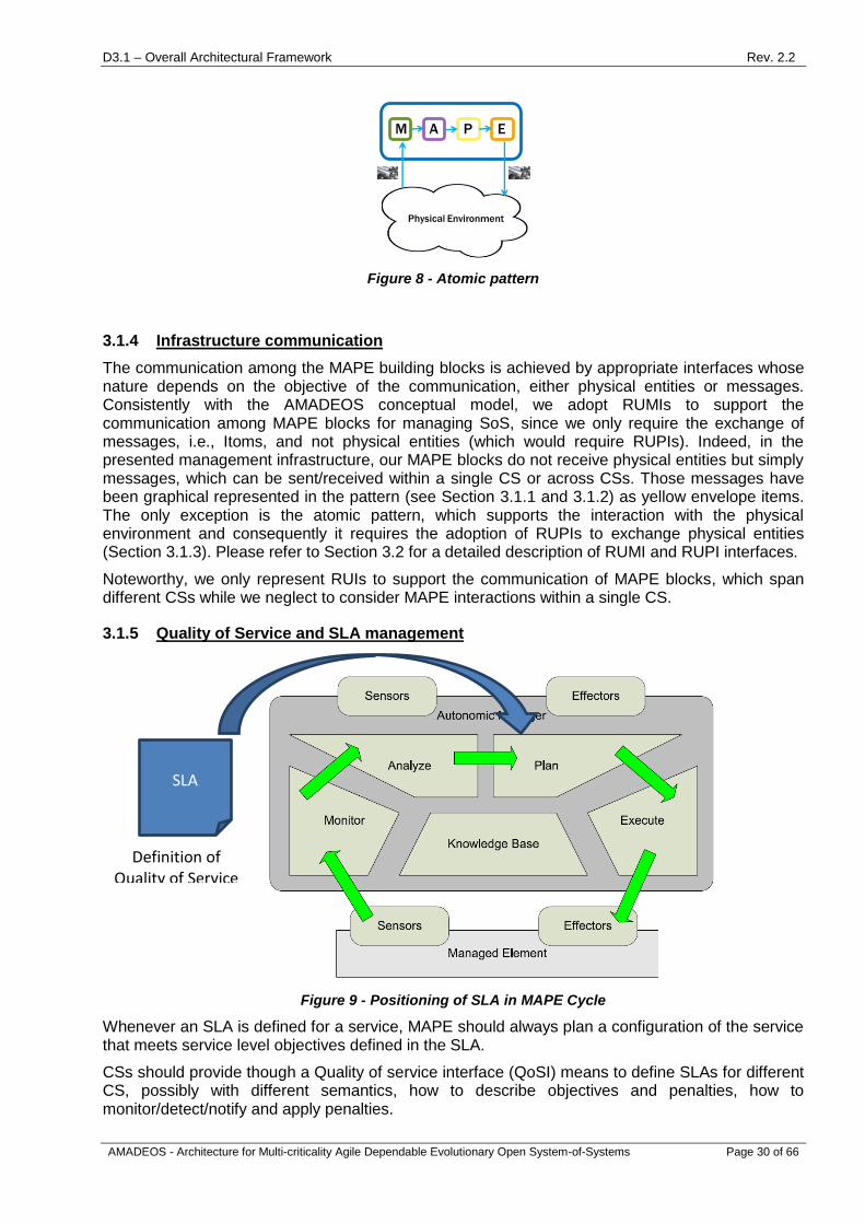
D3.1 – Overall Architectural Framework Rev. 2.2
AMADEOS - Architecture for Multi-criticality Agile Dependable Evolutionary Open System-of-Systems Page 30 of 66
PM EA
Physical Environment
Figure 8 - Atomic pattern
3.1.4 Infrastructure communication
The communication among the MAPE building blocks is achieved by appropriate interfaces whose nature depends on the objective of the communication, either physical entities or messages. Consistently with the AMADEOS conceptual model, we adopt RUMIs to support the communication among MAPE blocks for managing SoS, since we only require the exchange of messages, i.e., Itoms, and not physical entities (which would require RUPIs). Indeed, in the presented management infrastructure, our MAPE blocks do not receive physical entities but simply messages, which can be sent/received within a single CS or across CSs. Those messages have been graphical represented in the pattern (see Section 3.1.1 and 3.1.2) as yellow envelope items. The only exception is the atomic pattern, which supports the interaction with the physical environment and consequently it requires the adoption of RUPIs to exchange physical entities (Section 3.1.3). Please refer to Section 3.2 for a detailed description of RUMI and RUPI interfaces.
Noteworthy, we only represent RUIs to support the communication of MAPE blocks, which span different CSs while we neglect to consider MAPE interactions within a single CS.
3.1.5 Quality of Service and SLA management
Figure 9 - Positioning of SLA in MAPE Cycle
Whenever an SLA is defined for a service, MAPE should always plan a configuration of the service that meets service level objectives defined in the SLA.
CSs should provide though a Quality of service interface (QoSI) means to define SLAs for different CS, possibly with different semantics, how to describe objectives and penalties, how to monitor/detect/notify and apply penalties.
SLA
Definition of
Quality of Service

D3.1 – Overall Architectural Framework Rev. 2.2
AMADEOS - Architecture for Multi-criticality Agile Dependable Evolutionary Open System-of-Systems Page 31 of 66
3.2 RELIED UPON INTERFACES
Whenever two Constituent Systems (CSs) are connected to deliver a service from a service provider to a service requestor, a new interface must be provided at the boundary line between the two CSs (see Figure 10).
Figure 10 - Interfaces between two CSs.
We call this new interface a Relied Upon Interface (RUI), because the provision of the services at the SoS level relies on the proper operation of this new interface.
The RUI consists of two separate interfaces, a Relied Upon Physical Interface (RUPI) that is concerned with the exchange of physical entities (e.g., energy, material) across the RUI and a Relied Upon Message Interface (RUMI) that is concerned with the exchange of information between the two CSs across the RUI.
The Relied Upon Physical Interface (RUPI): The transport of physical entities across the RUI implies also the transport of information—we call this the intrinsic information transport-- about the properties of the physical entities. This intrinsic information transport is linked to the presence of a physical entity. We call the information about physical entities, which is detached from the physical entities extrinsic information.
The Relied Upon Message Interface (RUMI): The RUMI is an SoS Internal Message interface between constituent systems (CS) that enables the transport of extrinsic state information about the present and future state of the physical entities in the form of state messages without the presence of a physical entity. With extrinsic information it is possible to contemplate about and control the properties of the physical entities at a future instant, without the presence of a physical entity. Using the extrinsic information, we can specify the RUI service and the properties of the RT entities at future points in time by an appropriate RUI interface model.
A RUI should be a stable interface that hides the internal functions of a CS and the data representation at the interface to the environment.
Changes within a CS that do not affect a RUI are called minor changes, while those that affect the RUI are called major changes. Since major changes can affect many CSs of an SoS, these major changes must be coordinated among all CSs of an SoS.
RUMIs are often standardized by an accepted industry consortium or standard setting organization.

D3.1 – Overall Architectural Framework Rev. 2.2
AMADEOS - Architecture for Multi-criticality Agile Dependable Evolutionary Open System-of-Systems Page 32 of 66
Standardization of the Data Formats.
Standardization of the Explanation.
The placement and the specification of the RUIs form the backbone of an SoS Architecture.
3.2.1 The Relied Upon Interface Models
As depicted in Figure 10, the Left-CS Interface model describes the services of the Left CS that are provided to the Right CS. The Right-CS Interface model describes the services of the Right CS that are provided to the Left CS. The two interface models must be based on an agreed ontology explaining the meaning of the interface variables exchanged across the RUMI and must be compatible with each other.
Since the service at future points in time is explicated, a global time of proper precision among the CS is required.
3.2.2 Quality of Service and Service Level Agreement (SLA)
Before a service can be provided at a RUMI, a Service Level Agreement between the service requester and the service provider must be established that defines the desired quality of the service. The service level agreement contains:
• The description of the static properties of the service.
• The specification of the domains of the variables that are contained in a service request.
• The service level objectives (SLOs) to be attained in terms of values for the QoS metrics.
• The cost of the service.
• Penalties that will apply, if any of the SLOs in the SLA are not attained.
To negotiate the QoS a new interface on CSs is used:
The Quality-of-Service Interface (QoSI): The QoSI is an SoS interface between constituent systems (CSs) that enables the requester of the service to select the QoS aspects it is interested like performance, dependability, security, etc. To select the metrics for the selected aspects like response time for performance, and to define the service level objectives and penalties that will be contained in the SLA. It differentiates from RUMI as the latter is related to the business logic of the CS.
3.2.3 Request Reply Model of the RUMI
We distinguish between the request of a service at request instant tr and the actual delivery of the service at delivery instant td. At tr (which must be before td) a service request message containing the description of the requested service at td is sent to the service provider by the service requestor. The service provider responds with a service response message, hopefully indicating its commitment to provide the service at td. Thereby, the internal variables and algorithms used by the service provider to arrive the service response are not visible at the RUMI. At td the service provider controls its P-system such that the requested service is delivered.
3.2.4 Example: Smart Grid
To further explain the concepts introduced so far, we provide an example of a RUI specification between a micro-grid and an utility:

D3.1 – Overall Architectural Framework Rev. 2.2
AMADEOS - Architecture for Multi-criticality Agile Dependable Evolutionary Open System-of-Systems Page 33 of 66
Figure 11 - RUI of Smart Grid example.
3.2.4.1 PROBLEM: CIRCULAR DEPENDENCIES
The following settings and circular dependencies have to be considered within the example:
The micro-grid can be a consumer or producer of power.
The time-dependent price of power is determined by the utility.
The decision whether the micro-grid consumes power from the utility or delivers power to
the utility during a given interval depends, among other variables, on the price paid by the
utility.
The price offered by the utility during a given interval depends, among other variables, on
the amount of power consumed or produced by the plurality of micro-grids.
This circularity is resolved by a sequential iteration of automated negotiations about the price and the energy consumption/production of the micro-grid, where the rate of change of one iteration to the next is limited, such that with each iteration the possible rate of change decreases.
3.2.4.2 FLOW INTERFACE VS. DISCRETE EVENT INTERFACE
The RUPI between the smart grid and the utility is a flow interface, where the integral of the power flow over a time interval gives the energy flow in this interval.
We partition the time-line in 15 minute intervals and assume that the power flow and the price during an interval is constant. The start of each 15 minute interval is the delivery instant td. The planning horizon for the power flow is 24 hours, i.e., 96 fifteen minute intervals.
An iteration of negotiation consists of state messages that are exchanged every 15 minutes. The state message from the utility contains the anticipated price and the state message from the micro-grid contains the amount of power consumed/produced in each one of the 15 minutes interval.
3.2.4.3 SLA BETWEEN THE UTILITY AND THE SMART GRID
The SLA specifies a price band for the electric energy provided or accepted by the utility and boundaries for the electric power consumed or produced by a micro-grid. For the SLA the following rules have to be considered:
One hour before the delivery instant td the utility must commit the price for the interval that
starts at td.

D3.1 – Overall Architectural Framework Rev. 2.2
AMADEOS - Architecture for Multi-criticality Agile Dependable Evolutionary Open System-of-Systems Page 34 of 66
45 minutes before delivery instant td the micro-grid must commit the amount of energy
consumed or produced in the interval that starts at td for the committed price.
The rates of change of the energy prices and the amount of energy consumed/produced
are limited.
If a CS does not honour its committed values, a penalty applies.
3.2.4.4 SERVICE DESCRIPTION OF THE RUI
From the RUI requirements and interface descriptions above, a simple interaction between the micro-grid and the utility is specified. Every 15 minutes the utility will send a price vector with 96 fields (the next 24 hour period) containing the prices for consumed/produced energy. Based on the utility prices, the micro-grid will send a consumption/production vector with 96 fields (the next 24 hour period) every 15 minutes to the utility containing the planned amount of energy consumed/produced. One hour before the delivery instant td the utility will commit to the price and 45 minutes before the delivery instant td the micro-grid will commit to the amount of energy. Starting at td the micro-grid will consume/produce the committed energy at the committed price.
3.2.4.5 INTERFACE MODELS
Left CS (Micro-grid): Based on the energy prices received from the utility, the energy needed within the micro-grid and the storage state of the battery, the micro-grid will determine if the energy from the Photo-Voltaic Cells should be delivered to the utility or stored in the batteries.
Right CS (Utility): Based on the amount of energy consumed/produced by the plurality of micro-grids and the given energy prices on the spot market, the Utility will determine the energy prices for the next 24 hour period.
These procedures will be repeated iteratively until one hour before the delivery interval.
3.3 TOWARDS A TIME-AWARE SYSTEM-OF-SYSTEMS ARCHITECTURE
Time plays an important role in the development and operation of SoSs, as it helps to reduce the cognitive complexity required to design and integrate CSs, and it enables the real-time control of physical entities. Three main uses of time have to be considered in the development of an SoS, which correspond to the three concepts of time distinguished in [30].
Time to control real-time activities.
Time for timestamping of observations and temporal coordination of actions.
Reasoning about time.
When time is used to control real-time activities (e.g., reading sensors, computation, actuation or real-time communication), time is often directly encoded in the control algorithms in form of cycle times, deadlines, timeouts, schedules, etc. Many times no explicit real-time clock value exists in the implementation of these control activities that can be interpreted apart from the involved systems – like for instance the wall clock can be understood by many independent systems. Due to the tight integration of time into the control application, changing the time base (e.g., the control loop cycle time) will in most cases require to re-evaluate the validity of the control applications. In case of distributed control, and especially for control applications that involve more than one CS in an SoS, a common time base is required among the CSs which is synchronized with a bounded precision. Without an appropriate time base, the correct functionality of the control activities cannot be guaranteed.

D3.1 – Overall Architectural Framework Rev. 2.2
AMADEOS - Architecture for Multi-criticality Agile Dependable Evolutionary Open System-of-Systems Page 35 of 66
Timestamping of observations and temporal coordination of actions requires a clock value that can be added to the observation or action, respectively. Whenever the clock values of distinct CSs have to be related, the clocks of these CSs also need to be synchronized with a bounded precision. Changing the time base of the clocks for timestamping or coordination of actions does usually not mean that the timestamping or action triggering mechanisms have to be changed, as long as the requirements about the granularity of the clock and the precision of the synchronization are satisfied.
Reasoning about time implies that time is used as data for computation. For instance, comparing two timestamps, or changing the system behaviour based on the current time or season. A CS that only operates on timestamped data or that does not reference the current time (e.g., determining the duration between two timestamped events), is not required to have a synchronized time base. On the other hand, if the current time is referenced, also this use of time requires appropriate synchronization of clocks between the involved CSs.
In order for an SoS architecture to be time-aware, its CSs are required to have access to a synchronized global time base with bounded precision. Such a synchronized global time base can either be established by internal or external clock synchronization. Internal synchronization can be performed using a central master that periodically sends a message containing the current time, or in a distributed fault-tolerant configuration, where all CSs have to agree on a common clock value. The implementation of a distributed consensus based internal synchronization is very well suited for directed – and partly for acknowledged – SoSs with a high requirement on reliability that experience low dynamicity. But this approach cannot be applied for highly dynamic SoSs – in many cases collaborative or virtual SoSs – where the number of CSs continuously changes, as the consensus protocols require the number of participating CSs to be known. The centralized master approaches (i.e., with one single or multiple masters) are also applicable for highly dynamic SoSs, except if dynamic cluster building is allowed and each cluster would need its own master. For instance, in an SoS with vehicle-to-vehicle communication, whenever at least two vehicles encounter each other they build a cluster to exchange information. In the whole SoS thousands of such clusters might exist simultaneously. If one vehicle would spontaneously be connected to more than one cluster simultaneously, a complex synchronization between the masters would be required.
In contrast, external synchronization relies on a time source that is external to the SoS, and each CS has to synchronize to that external source (e.g., a Global Navigation Satellite System (GNSS)). Since the external clock source has to be available at all CSs (i.e., either directly or indirectly using a time gateway), the CSs are continuously synchronized even if they belong to different clusters.
Time-awareness allows for temporally ordering observed events and temporally correctly executing timely available actions in a distributed setting. Naturally, in case the communication or computation subsystem or both fail to deliver or execute an action at its deadline, the execution cannot be guaranteed to be temporally correct. However, even in most general time-aware architectures the temporal consistency of observed events – no matter which component observed them – can be always established.
The Time-Triggered Architecture (TTA) is a time-aware architecture that additionally requires time-triggered execution of the communication and computation actions of components according to a conflict-free schedule. This additional requirement imposes strong constraints on communication and computation subsystems, but also allows for hard guarantees about the timely execution of actions. Ultimately this leads to deterministic and composable models of systems that have low cognitive complexity.
Conceptually, the TTA is a component-based integrated architecture where components interact with their environment solely by the exchange of messages over interfaces. The component is the unit of design and the unit of fault containment. Components interact among themselves solely by the exchange of messages over Linking Interfaces (LIFs). The LIF of a component is precisely defined in the value, the time, and the meta-level/semantic domains. LIFs represent the possibly complex internal structure of a component.

D3.1 – Overall Architectural Framework Rev. 2.2
AMADEOS - Architecture for Multi-criticality Agile Dependable Evolutionary Open System-of-Systems Page 36 of 66
Systems based on the TTA have been mostly considered as stand-alone systems or systems that can be integrated as Constituent Systems (CSs) in directed Systems-of-Systems (SoSs), i.e., SoSs with a central managed purpose and central ownership of all CSs. The TTA offers several advantages with respect to functional and non-functional system attributes over event-triggered architectures:
Temporal Consistency: the temporal order of events is consistently observed by all components in the system.
Deterministic Communication: messages are transmitted in the same order on all replicated channels, and are consistently received by all components.
Deterministic Task Execution: the execution of distributed tasks can be controlled such that the end-to-end delay of a sequence of tasks can be minimized (e.g., in a control loop the time between reading the sensors and applying new set points for the actuators).
Fault Tolerance: faults in one component cannot propagate to other independent components due to temporal and spatial isolation of components.
Composability: components that have been developed and tested independently can easily be combined without affecting the temporal and spatial properties of the individual components.
Certifyability: since faults cannot propagate to other components, certification can be done for each individual component instead of the system as a whole. This allows reducing cost by certifying different components of the system for different criticality levels.
Primarily the TTA is intended for the automotive, railway, aerospace, and industrial domains where safety and reliability are the most critical requirements. Prominent TTA realizations are:
Time-Triggered Protocol/C (TTP/C): A fault-tolerant time-triggered fieldbus for vehicles and industrial applications.
TTEthernet (TTE): Extends Ethernet by introducing time-triggered, rate-guaranteed, and best-effort traffic classes.
ACROSS Multiprocessor System-on-Chip (MPSoC): This certifiable architecture with support for mixed criticality is based on a Time-Triggered Network-on-Chip (TTNoC) and has architectural support for reconfiguration, diagnosis, input/output and data storage.
3.3.1 Resilient Master Clock
As previously introduced, many SoSs have the requirement of having time synchronization among their CSs. In AMADEOS project we want to have internal clock synchronization, where the time source is internal to the SoS.
It is a basic assumption in AMADEOS that every CS of an SoS has access to a global time. In addition, it is strongly important to have a clock, which is able to self-estimate the synchronization accuracy. Having such information allows the system to assert its operation state and consequently operate (e.g. normal mode; degraded mode; etc.). Thus, the awareness of clock synchronization increases the system resilience. To satisfy this assumption, we introduced a resilient fail-silent master clock based on satellite-based time synchronization (e.g. GPS or Galileo signals).
Such resilient clock will have to be based on hardware COTS; and wherever possible, also software COTS shall be used. The clock is constituted by (most likely, two) independent oscillators and GPS devices, complemented by an acceptance test, and includes software clock control techniques:
i) to provide a self-estimation of the quality of clock synchronization and

D3.1 – Overall Architectural Framework Rev. 2.2
AMADEOS - Architecture for Multi-criticality Agile Dependable Evolutionary Open System-of-Systems Page 37 of 66
ii) to extend the holdover period of the clock by compensation of local clock deviations, especially in case of absence of the GPS signals (e.g., the GPS signal fails or is corrupted by a security incident).
The solution shall be compatible and integrable within IEEE 1588 (Precision Time Protocol) synchronization networks for industrial processes, being able to act as a resilient master clock for such networks.
The resilient clock shall be able to cope with clock (crystal oscillators) deviations caused by physical environmental variations, like of the temperature, pressure, humidity variations or, voltage. Additionally, the clocks will be equipped with correction techniques based on COTS sensors to compensate local clock deviations and avoid asynchronous clocks in SoSs in the absence of GPS signals. The oscillators of the fail-silent clocks will be adjusted and calibrated such that when the GPS signal fails (or is corrupted due to a security incident) they maintain the global time within a required accuracy for a longer time duration before the GPS becomes available again. This will require the application of local clock techniques, firstly to predict the behaviour of the clock, and then to estimate the quality of synchronization through a bounded precision technique, which compares the deviation of the clock with respect to the estimated boundaries of its predicted behaviour. As soon as the GPS signal is available again, the fail silent clock will align its time message with the GPS signal.
3.4 DEPENDABILITY ASPECTS
One key property of systems-of-systems is their dependability. Evolutionary SoS must be able to guarantee certain dependability aspects, such as security, privacy, safety, reliability, etc. These aspects can be thought of as the dependability of the system.
3.4.1 Multi-level security for Systems-of-Systems
High assurance systems are built on underlying high assurance operating systems. Historically these secure operating systems were designed to be secure general-purpose operating systems, based on security kernels and a Trusted Computing Base. The Orange Book [31] defines the Trusted Computing Base as ’the totality of protection mechanisms within a computer system’, which means that all security-critical functionality must be included in the TCB, leading to the TCB becoming larger and larger. It has become clear however, that the TCB has to be kept small in order to be verifiable, hence the failure of these secure general-purpose operating systems. This led to the introduction of the multiple independent levels of security (MILS) [32] concept, which separates the security mechanisms into smaller, more manageable components.
Traditionally high assurance systems are based on a military model of secure operating systems, which includes the multi-level security (MLS) concept. MLS assigns different classification levels to data, ranging from ‘unclassified’ to ‘top secret’. The task of the secure operating system then becomes ensuring that entities can never access data with a classification level higher than their own. Security models such as the Bell-LaPadula model [33] can be used to enforce this behaviour. Bell-LaPadula ensures data confidentiality by allowing reading of data at or below the subject’s security level, and by allowing writing of data at or above the subject’s security level. In contrast, the Biba model ensures integrity of data [34]. Under the Biba model, data can be read at higher levels and written to lower security levels, which is the opposite of the Bell-LaPadula model.
MILS adapts the MLS concept to make it easier to evaluate. Instead of only using MLS, MILS considers three types of components: single-level secure components, multiple single-level secure components and multi-level secure components. The first only handle data at one specific security level. The second handle data at multiple levels of security, but never simultaneously. The third actually mingle data at different levels of security. This separation greatly simplifies the rigorous analysis of the system.
The MILS system architecture is a hierarchical system architecture where each layer provides security mechanisms that can be used by the layer above. On top of this layered architecture of

D3.1 – Overall Architectural Framework Rev. 2.2
AMADEOS - Architecture for Multi-criticality Agile Dependable Evolutionary Open System-of-Systems Page 38 of 66
security mechanisms a mix of trusted and untrusted applications can run isolated from each other on a shared computational system. The security mechanisms must posses the following four properties: they must be always invoked, non-bypassable, tamperproof and evaluatable. It is this last property which led to the development of MILS. In order to be evaluatable the security mechanisms have to be small and simple enough to be formally verified.
The MILS architecture consists of three layers of security mechanisms: the MILS separation kernel, the middleware layer and the application layer. The separation kernel (SK), or partitioner, enforces data separation and limits information flows within a single microprocessor, providing both time and space partitioning. It is also responsible for ensuring every partition gets a fair share of the resources of the microprocessor. The SK provides four basic security mechanisms: data separation, which ensures that any action by an executing partition does not affect the state of any of the other partitions and vice versa; information flow, which defines the authorized communication channels and mechanisms for communication between partitions; sanitization, which ensures shared resources are cleaned before a new partition uses them; and damage limitation, which ensures that faults cannot propagate over different partitions. In order to be able to do this certain hardware support is required, namely: sufficient processing power, atomicity, privileged mode of operation, a memory management unit, instruction traps, timing control, I/O access limitation. However most commercial microprocessors and motherboards already provide these features.
Individual partitions may also run on separate processors. In this case only one of the four basic security mechanisms must be provided, namely information flow controls. The other three, data separation, sanitization and damage limitation, are automatically provided by the physical separation of the partitions. In case of an open communication medium information flow control can be obtained by means of using cryptography. In case of a closed communication medium, trusted device drivers or logical trusted network interface units can be used as guards to enforce the information flow policy.
The middleware layer includes services such as resource allocation of shared data storage devices, object-oriented communication between partitions on multiple processors, communication services between partitions on multiple processors or real-time data distribution services. Whereas the SK (partitioner) is mostly concerned with data processing within a single microprocessor, middleware services are end-to-end. The middleware layer provides three security mechanisms: labelling all messages with the sender’s security classification and unique id; filtering messages that are not appropriately labelled; and maintaining information flow controls.
The application layer can contain Single-Level Secure (SLS), Multiple Single-Level Secure (MSLS) and Multi-level Secure (MLS) components. Of these three types the MLS components are the ones requiring the highest level of security verification, since they co-mingle data at different classification levels. Examples for application layer components are: a collator, which processes data of different classification level, transmitting it at a single higher classification level. This is clearly an MLS component. A downgrader transmits data at a classification level which is not necessarily the highest among the inputs it receives. Again this is an MLS component. An encrypter is a third example of an MLS component. A MILS message router is an example of a MSLS component, since it routes messages of different classification levels, but never changes the classification level of these messages.
We will apply this concept to use cases for Systems-of-Systems. The main idea is to consider possible use cases for a certain SoS and derive the functionalities the SoS should perform. For each of these functionalities we then consider how security-critical they are, also taking into account such factors as whether they are only used for specific use cases or if they are used in different scenarios. We then consider the various components that comprise the SoS and match the functionalities to certain components. The multi-level aspect here consists of grouping the most security-critical functionalities together in a component that can be made very secure and can be rigorously verified. This allows the possibly much more complicated, but less security-critical functionalities to be performed by less secure components.

D3.1 – Overall Architectural Framework Rev. 2.2
AMADEOS - Architecture for Multi-criticality Agile Dependable Evolutionary Open System-of-Systems Page 39 of 66
As an example we describe how this concept could be applied to the Electric Vehicle charging use case of Work Package 4. In applying MILS, we deconstruct functions in EV charging so the trusted components are as small and simple as possible. Security of the EV charging system should only depend on a very small number of trusted components. Non-critical functions will be outside the trusted components. Examples of some of the functionalities for this use case are: authenticate the customer, allow firmware updates to the charging station, maintain a whitelist of customers allowed to charge when the system is off line, etc. Clearly, the firmware updates are the most security-critical of the three, since by changing the firmware you can essentially override all the security mechanisms that were in place. The local white list is the least security-critical, since tampering with this would only allow a fraudster to charge his car when the system is off line, which we assume is not a common occurrence. This means that the component handling the firmware updates should be provably secure. However, the part of the memory where the whitelist resides can be made less secure, thus reducing the overall cost and effort of securing the system.
The MILS approach by itself does not compose by default. That is, one cannot build a secure system through simply gluing together secure components. Several articles have been published about how to create an evaluation and certification scheme for MILS through a component security integration approach [35] [36]. This approach allows us to build a high-assurance, secure MILS system by composing secure MILS components. In a two-level MILS approach, we divide security into the policy level and the resource-sharing level. In addition to identifying all the functionalities and components, we must specify the interfaces and properties for each component. That is, it must be specified how each component interacts. There can be no interaction outside the known interfaces, even in the case of a fault or malicious untrusted component. The component properties must be evaluatable locally and when components are composed. Components fall into two categories: foundational and operational. Foundational components (at the policy level) securely share physical resources, such as a separation kernel or file system. Operational components (at the resource sharing level) are at the application layer, such as middleware.
In the case of the AMADEOS approach to SoS security, we are interested in building high-assurance, secure systems of systems through composition of secure constituent systems (CSs). Thus, we consider foundational CSs that use relied-upon physical interfaces (RUPIs) to communicate. We also consider operational CSs that use relied-upon message interfaces (RUMIs) to communicate. As described in Section 3.2, the RUIs are well defined, which facilitates use of the MILS component security integration approach.
3.4.2 Trust and Trustworthiness
Another important aspect of dependability is the trustworthiness of the system and the trust that the users of that system hold in it. Trust is the belief held by a human of the trustworthiness of another human or service [37]. With respect to the dependability of a system, unless users trust that system, they won’t use it, regardless of the actual trustworthiness of the system. When developing a system of systems architecture, trust and trustworthiness must be active considerations [34].
Trust, as it is a characteristic of human users, can only be estimated by measuring the behaviour of the users within the system. While approaches to this exist [36], it typically entails monitoring all user interactions, and this has a knock-on effect on privacy. Trustworthiness, however, is an aspect of the system, and can therefore be more readily measured at runtime [38]. Designing a trustworthy system of systems involves using a “trustworthy-by-design” software development process, such as that proposed by the OPTET FP7-ICT project2.
3.4.3 Safety and Reliability
Safety and Security are often linked, although they can have opposite outcomes. For example, a door failing safely typically indicates that it is open while failing securely typically indicates that it is locked. With respect to architectures, safety has a significant history in critical infrastructure. Safety
2 http://www.optet.eu/

D3.1 – Overall Architectural Framework Rev. 2.2
AMADEOS - Architecture for Multi-criticality Agile Dependable Evolutionary Open System-of-Systems Page 40 of 66
tends to be highly regulated and standardised, such as for example energy production and supply in the electrical grid. In comparison, security standardisation is not as well developed. The common criteria (ISO/IEC 15408) for computer security certification is a framework where users can specify their security requirements, vendors can make claims regarding the security attributes of their products and testing laboratories can verify these claims with respect to the specific requirements.
3.4.4 Legacy System Integration
It is also important to provide the ability to use legacy systems within a system of systems. This is particularly true when considering systems that have long lifetimes, such as electrical grid or industrial automation. Some systems in the electrical grid, such as equipment used in electrical substations, are expected to last decades or even a century with proper maintenance. It would be cost prohibitive to replace all of these systems, so they must be integrated securely.
One way to help ensure that legacy systems are integrated into the SoS in a secure manner is to properly define all of the interfaces that are being used. That is, explicitly detail each interface and what kind of information is communicated. We can consider each legacy system as a CS that communicates via RUMIs and RUPIs. Any interface that is not necessary should be removed or disabled. This reduces potential attack vectors and is called “hardening” the system.
3.5 EVOLUTIONARY ASPECTS
A SoS evolves over time as constituent systems are modified, replaced or added, or due to its relevant environment (gradually) changes. This evolution is driven by incremental, new, and changing requirements of the SoS. An architectural framework for SoS should provide a tool aimed at predicting possible evolutionary paths based on anticipated requirements and use-cases.
3.5.1 Scenario-based Reasoning for SoS Architecture design
In architectural systems engineering the use of scenarios is not uncommon. It is a cost-effective means of controlling risk and to maintain system quality throughout the processes of software design, development and maintenance [39, 40]. Preparing for evolution of an SoS, a scenario-based approach can also be adopted to guarantee that the development that an architecture undergoes is sensible, i.e. it must guarantee that the quality goals of the system are still met.
By using scenarios to guide the design of an SoS architecture, the context of the envisioned SoS is incorporated into the possible design choices by the architect. Established scenarios provide a narrative, which enables communication about future requirements and capabilities between different stakeholders [40]. Scenario-based design is a user-based approach in which different use-cases of a system are defined by narratives, from which a lower-level description of the system can be extracted. However, not every SoS can be described by narratives focussed around use-cases and user interactions. Moreover, a narrative provides the intended use of a system from the perspective of a single expert or end-user, whereas in the context of SoS single use-cases are more related to the constituent systems than to the SoS as a compound structure. Therefore, a more methodical approach is needed, in which multiple experts can define relevant states and variables that may describe the possible evolution of the SoS and its relevant environment.
Scenario-based reasoning (SBR) [41] provides a methodical approach to generate and explore scenarios. In the SBR approach, scenarios are built from a set of variables, and each combination of variable states makes up a single scenario. Relevant scenario variables are those that influence the design of the system, such as variables that denote for example: environmental conditions, organizational dynamics, economic conditions, technological development, and interactions with the system form a user perspective. Such variables can have dependence relations between them which are, for example: causal, functional, influential, or probabilistic. For instance, enabling a certain security feature in the system will typically have an influence on its usability.
SBR enables what-if exploration to reason about possible future conditions and consequences for the architecture of an SoS. Through the analysis of different scenarios and their dependencies,

D3.1 – Overall Architectural Framework Rev. 2.2
AMADEOS - Architecture for Multi-criticality Agile Dependable Evolutionary Open System-of-Systems Page 41 of 66
inconsistencies can be revealed that may have consequences for the eventual architectural design of the system. Through the identification (also generation) of scenarios from a model describing the context under which the SoS will be deployed and the possible future uses of the system, evolving requirements may be elicited. By thinking about how to operationalize these requirements, insights are acquired about how they map to the architectural design of the system.
Figure 12 - A small example causal model for SBR.
Figure 12 shows a small sample model from an environmental point of view, from which possible scenarios can be extracted for analysis. It depicts causal relations between the possibility of providing financial incentives for electrical vehicle use and energy production by consumers. Increased popularity of these use-cases in turn has an effect on the load placed on the local neighbourhood grid.

D3.1 – Overall Architectural Framework Rev. 2.2
AMADEOS - Architecture for Multi-criticality Agile Dependable Evolutionary Open System-of-Systems Page 42 of 66
4 AMADEOS ARCHITECTURAL FRAMEWORK
In this section we describe the preliminary architectural framework of AMADEOS. First, we describe the overall view of the framework giving an high-level perspective of activities and artefacts involved in SoS design phases. Second, we specialise the framework for each viewpoint by also showing its support with an illustrative automotive scenario.
4.1 HIGH-LEVEL VIEW
The high-level representation of the architectural framework is shown in Figure 13 as a pyramid made of different layers. The pyramid is composed of four levels:
Mission.
Conceptual Level.
Logical level.
Implementation level.
As it is evident from the figure, the Mission is a unique block, while the remaining levels are
organized in slices, each corresponding to a specific AMADEOS viewpoint.
Mission
SoS
Framework
Input:
� Conceptual model
� Meta-requirements
Output: SoS requirements (for each viewpoint)
Enhanced Design
Contextualization and Realization
Input:
� SoS requirements
� SoS Profile
� SoS Management Infrastructure (MAPE), RUI, Resilient Master Clock,
Dependability Support Units, Evolutionary Support Units
Output: SoS Logical Description (Platform Independent Architecture)
Input:
� SoS Logical Description
� Domain/Enterprise specific techniques
Output: Instrumented SoS with AMADEOS solutions (Platform-specific Architecture)
AMADEOSViewpoint 1
AMADEOSViewpoint 2
AMADEOSViewpoint n
SoS
Requirements Definition
Figure 13 - AMADEOS Architectural Framework.
The starting point of the architectural framework consists in gathering the Mission of an SoS. The mission is commonly formalized by means of a document of intents created by enterprise

D3.1 – Overall Architectural Framework Rev. 2.2
AMADEOS - Architecture for Multi-criticality Agile Dependable Evolutionary Open System-of-Systems Page 43 of 66
managers having in mind a high-level perspective of the system and a clear definition of business-related issues. Input for this level is a shortened version of the glossary, to illustrate main SoS concepts, and to identify the relevant arguments that should be captured in the mission. The output is captured in the document of intents written in natural language to formalize the overall objectives and functionalities of an SoS.
At the Conceptual Level, the number of viewpoints to be considered for a specific SoS is decided, e.g., it could be the whole set of viewpoints considered in AMADEOS or a subset of them. The decision will mostly depend on the target SoS and its mission; however as far as in AMADEOS we are limiting our observation to collaborative SoS, we propose a set of viewpoints that must be mandatorily considered. Inputs for this level are:
the document of intents formalizing the SoS mission.
the SoS AMADEOS conceptual model [42], which identifies the main concepts and
relationships to exploit when describing an SoS.
the SoS AMADEOS meta-requirements [29], which can clarify how to describe each
viewpoint and their relations and which can guide the identification of requirements for
specific SoS instances.
Given the above inputs, the following outputs are produced:
For each viewpoint (corresponding to a slice of the pyramid), the SoS is examined and
described. The resulting description should be the requirements of the SoS (these can be
expressed in natural language, as well as using formalisms for the description of
requirements).
Connections between the different viewpoints are defined.
Tools and techniques to support requirements definitions and formalization can be adopted to achieve the production of the outputs of this level.
The Logical Level provides support for designing an SoS. This phase consists in a intermediate step between the requirements specification at Conceptual Level and the Implementation Level. The design is not limited to the architecture and RUMI viewpoint (as it is usually done in traditional system engineering), but all viewpoints are here involved. Inputs for this level are:
viewpoint-based requirements.
the SoS profile as defined in D2.2 which semi-formalizes AMADEOS viewpoints.
the building blocks identified in Section 3.
Given the above inputs, the outputs of this level consist in a description of the SoS in a semi-formal
language (SysML), for the different viewpoints. The description at this stage is most likely platform
independent (e.g., does not mention if a specific CS is running Windows or Linux).
The Implementation Level leads to the implementation/realization/deployment of the SoS, or of some portions of it (most likely, the output will be an integration of new CSs with already existing and deployed CSs). Input for this level consists in the logical architecture defined at the previous level and domain/enterprise specific techniques. The latter logical architecture is then refined and instrumented with domain/enterprise specific technologies which belong to the enterprise implementing the SoS instance.
The high-level representation of the framework focuses mainly on eliciting the set of phases and the inputs/outputs required/produced at each state without detailing the applicable processes. To this end, in order to better explain the former processes, we introduce the process-based view depicted in Figure 14 where basic tasks are listed and explained. This gives a more detailed description of the relationships and evolution of the main artefacts produced in each level of the pyramid (see Figure 13) and the relations between levels (through the top-down processes of

D3.1 – Overall Architectural Framework Rev. 2.2
AMADEOS - Architecture for Multi-criticality Agile Dependable Evolutionary Open System-of-Systems Page 44 of 66
refinement and instantiation, and bottom-up processes of generalisation and abstraction). The artefacts categories at each level are intended to be generic enough to fit all the viewpoints.
Figure 14 - Refinement and evolution of processes in Architectural Framework Design
In Figure 14, the four AMADEOS architectural levels introduced in Figure 13 are again represented, but with the emphasis on the cycles that take place both within each of the levels, and across the complete stack.
On the Mission Level, a relatively slow-paced cycle takes place to address the continuous synchronization between the operational needs, the currently targeted capabilities of the SoS architecture and the technological possibilities to achieve the needs. At this stage enterprise managers iterate the above phases to determine the mission of the SoS which is then formalized in a document of intents. They analyse the current needs of the organization and they map them with the possible target solutions which may be implemented.
On the Conceptual Level the alignment between the overall envisioned concepts and the SoS domain takes place at a more frequent pace. On this level the AMADEOS concepts which are relevant to achieve the mission are extracted from the document of intents and then filtered based on the viewpoint to which they belong. Further details may be added at each viewpoint descriptions to support the targeted capabilities within the SoS domain. The AMADEOS concepts can also be adapted and extended to support new SoS architecture concepts that emerge from the targeted domain. Connections among viewpoints descriptions are early identified at this stage before similar concepts are aligned with each other, if needed.
On the Logical Level, cycles occur at a more rapid pace and are used to ensure that all desired functionalities and qualities (as stated in the viewpoint-driven requirements) are supported by the
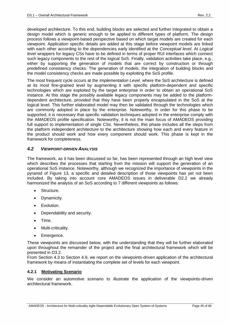
D3.1 – Overall Architectural Framework Rev. 2.2
AMADEOS - Architecture for Multi-criticality Agile Dependable Evolutionary Open System-of-Systems Page 45 of 66
developed architecture. To this end, building blocks are selected and further integrated to obtain a design model which is generic enough to be applied to different types of platform. The design process follows a viewpoint-based perspective based on which target models are created for each viewpoint. Application specific details are added at this stage before viewpoint models are linked with each other according to the dependencies early identified at the Conceptual level. At Logical level wrappers for legacy CSs have to be defined in terms of proper RUI interfaces which connect such legacy components to the rest of the logical SoS. Finally, validation activities take place, e.g., either by supporting the generation of models that are correct by construction or through predefined consistency checks. The generation of models, the integration of building blocks and the model consistency checks are made possible by exploiting the SoS profile.
The most frequent cycle occurs at the Implementation Level, where the SoS architecture is defined at its most fine-grained level by augmenting it with specific platform-dependent and specific technologies which are exploited by the target enterprise in order to obtain an operational SoS instance. At this stage the possibly available legacy components may be added to the platform-dependent architecture, provided that they have been properly encapsulated in the SoS at the logical level. This further elaborated model may then be validated through the technologies which are commonly adopted in place by the enterprise. Noteworthy, in order for this phase to be supported, it is necessary that specific validation techniques adopted in the enterprise comply with the AMADEOS profile specification. Noteworthy, it is not the main focus of AMADEOS providing full support to implementation of single CSs. Nevertheless, this phase includes all the steps from the platform independent architecture to the architecture showing how each and every feature in the product should work and how every component should work. This phase is kept in the framework for completeness.
4.2 VIEWPOINT-DRIVEN ANALYSIS
The framework, as it has been discussed so far, has been represented through an high level view which describes the processes that starting from the mission will support the generation of an operational SoS instance. Noteworthy, although we recognized the importance of viewpoints in the pyramid of Figure 13, a specific and detailed description of those viewpoints has yet not been included. By taking into account core AMADEOS issues in deliverable D2.2 we already harmonized the analysis of an SoS according to 7 different viewpoints as follows:
Structure.
Dynamicity.
Evolution.
Dependability and security.
Time.
Multi-criticality.
Emergence.
These viewpoints are discussed below, with the understanding that they will be further elaborated upon throughout the remainder of the project and the final architectural framework which will be presented in D3.2. From Section 4.3 to Section 4.9, we report on the viewpoints-driven application of the architectural framework by means of instantiating the complete set of levels for each viewpoint.
4.2.1 Motivating Scenario
We consider an automotive scenario to illustrate the application of the viewpoints-driven architectural framework.

D3.1 – Overall Architectural Framework Rev. 2.2
AMADEOS - Architecture for Multi-criticality Agile Dependable Evolutionary Open System-of-Systems Page 46 of 66
A consortium of automotive companies, road operating companies (e.g., the Austrian ASFiNAG), emergency organizations, traffic management companies, governments, etc. plan to build an SoS with the purpose to avoid collisions of vehicles on road intersections. The SoS is clearly collaborative, since different classes of CSs from different stakeholders will have to interact in order to reach the objective. In such an SoS each vehicle has the ability to share information with others in their immediate area. To assure that collisions are actually avoided it is necessary the information exchanged among cars take place promptly before the cars collide.
Since vehicles are electrical entities, it should be possible to support the infrastructure to charge them from the household and from charging points on the road. Vehicle charging operations should also be carried out avoiding possible damages made to the charging infrastructure by attackers and assuring that the charging operations will be effectively and efficiently completed.
Beyond the former objectives the consortium has as goal the one of distributing the traffic on the roads such that traffic jams shall be avoided as good as possible. Thus, beyond communicating with each other to avoid collision, vehicles may also have to be monitored by resilient monitoring traffic systems thus relieving congestion by means of traffic lights.
When a vehicle is constructed, the communication, and data exchange standards are defined and they are difficult to update after this point. Therefore, the SoS must be able to support such legacy systems and also evolve over time to support future capabilities. Some of the old features of the old SoS (e.g., V2X communication) are combined with new features to achieve the new goals. So, an evolution of the existing SoS has to be achieved to its architecture.
As indicated by the automotive scenario the mission to achieve consists in avoiding collision among cars, traffic jams and supporting charging operations of the electrical vehicles trough the network.
4.3 VIEWPOINT OF STRUCTURE
The Structure viewpoint concerns with representing the overall structure of the SoS. It focuses on architectural concerns of an SoS an it is closely related to other issues like SoS constraints, RUMI and semantics of communication. Indeed, defining interfaces among CSs is important as this stage to support their communications.
In the following subsections the AMADEOS architectural framework is described from the viewpoint of structure. This entails viewing the structure from the conceptual level to the logical design and finally to how the architecture will be implemented.
4.3.1 Conceptual Level
Input:
SoS Mission, overall objectives and functionalities (document of intents).
SoS Constraints meta-requirements: please refer to Section 8.2 of D1.1.
Architecture & RUMI meta-requirements: please refer to Section 8.3. of D1.1.
Semantics of Communication meta-requirements: please refer to Section 8.4 of D1.1.
Conceptual model: please refer to Section 2.1, 2.3, 2.4 and 2.5 of D2.2.
The input to the conceptual level of an SoS is the mission (or vision). This entails the overall objectives of the SoS as well as the required functionalities. The structure viewpoint entails examining these objectives and determining the constraints of the interfaces, and the communication, between constituent systems. Unlike the other viewpoints, the structure viewpoint places restrictions upon the activities of the SoS.
From the abovementioned sections in D1.1, we can identify the most important meta-requirements that must be taken into consideration:
[CONSTR 1] When describing an SoS, constraints shall be identified and defined.

D3.1 – Overall Architectural Framework Rev. 2.2
AMADEOS - Architecture for Multi-criticality Agile Dependable Evolutionary Open System-of-Systems Page 47 of 66
[CONSTR 4] For each class of constraints, the constraints shall be identified and respected in the system.
[CONSTR 11] A SoS and/or its entities may be subject to the application of standards.
[CONSTR 15] A SoS has its own system life which may be described by attributes as lifecycle, process, time of life, role.
[ARCH 1] A SoS shall have a type, to be selected amongst Directed, Acknowledged, Collaborative and Virtual SoS.
[ARCH 2] Two or more CSs may be organized in formal hierarchical or holarchical levels to form another CS or an SoS.
[ARCH 3] CSs shall interact exclusively through RUMIs to exchange Itoms.
[ARCH 9] The RUMI shall describe the Semantic of Communication through the definition of Itoms.
[SEM 1] Semantic of communication shall be described by Itoms exchanged through the RUMIs.
[SEM 7] Semantic of communication shall be defined at the boundaries of any system.
By addressing these meta-requirements in the context of the specific mission, a set of structural requirements can be identified that restrict the overall architecture that will be eventually delivered. For example, from [CONSTR 11], standards compliance of one or more CSs may be very important, particularly in use cases such as in the Smart Energy domain.
The output of the conceptual level consists of:
Structure requirements: A set of requirements that relate to the structural architecture of the
SoS.
These meta-requirements, along with the remainder that are identified in D1.1, form the input to the logical level.
4.3.2 Logical Level
Input:
“Structure” requirements.
SysML profile defined in D2.2.
Building blocks defined in Section 3.
The logical design of an SoS architecture will be based upon the Structure requirements identified at the conceptual level and the building blocks identified in Section 3, along with the SysML profiles identified in D2.2.
The SysML Block Definition Diagram (BDD) is used to model the topology and the relations of an SoS. Blocks in SysML BDD are the basic structural element used to model the structure of systems. A Block is depicted as a rectangle with compartments that contain Block. A Block provides a unifying concept to describe the structure of an element or a system3. This type of diagram helps a system designer to depict the static structure of an SoS in terms of its CSs systems and their possible relationships. By means of BDDs it will be possible to model the static structure of CSs, their interfaces and how the communication among CSs is achieved.
3 see D2.2 for a more detailed discussion regarding Block Definition Diagrams.

D3.1 – Overall Architectural Framework Rev. 2.2
AMADEOS - Architecture for Multi-criticality Agile Dependable Evolutionary Open System-of-Systems Page 48 of 66
The output of the logical level will be a platform independent SoS architecture specification from a structural point of view. This will consist of the outline of the CSs identified by the requirements and the RUMIs that specify the interactions between these former CSs.
4.3.3 Implementation level
Input:
SoS structural architecture specification described using the AMADEOS profile.
On this level, the platform independent structural design from the enhanced design level is further concretized using specific contextual requirements, towards building the SoS structural architecture. For example, specific CSs may already exist and may need to be integrated. In the structural viewpoint, this will lead to specific RUMIs that are used to define how CSs will interact. These RUMIs consist of the communication protocols that define the messages that will be shared between CSs. The implementation level is very specific to the actual CSs involved and the operational context.
Output:
Fully contextualized SoS structural architecture.
4.3.4 Use case instance
Consider an SoS of communicating vehicles, where each vehicle has the ability to share information with others in their immediate area. However, when a vehicle is constructed, the communication, and data exchange standards are defined and they are difficult to update after this point. Therefore, the SoS must be able to support such legacy systems and also evolve over time to support future capabilities.
In such an SoS, the structural requirements specified on the conceptual level in Section 4.3.1 will include adhering to the standardised communication protocols defined by the industry standards bodies. These communication protocols will then place requirements upon the types, frequency and number of messages that can be exchanged between constituent systems (in this example, individual vehicles). As stated above, these requirements are long-lived and not trivial to change in “future” older vehicles. On the logical level, these structural requirements then will influence the specification of RUMIs that define the interactions between vehicles. Finally, on the implementation level, using these RUMIs the implementation of the CSs will maintain compatibility with both existing and new vehicles in the future.
4.4 VIEWPOINT OF DYNAMICITY
Dynamicity refers to short-term changes in an SoS. Indeed, dynamicity if the property of an entity that is constantly changing in terms of offered services, built-in structure and interactions with other entities, c.f. D2.2. Changes may have many effects on the SoS. For example, changes can lead to new emergence phenomena. They may be well-planned in advance, or may be abrupt.
4.4.1 Conceptual Level
At the conceptual level, the input includes:
SoS Mission, overall objectives and functionalities (document of intents).
Dynamicity meta-requirements: please refer to Section 8.5 of D1.1.
Conceptual model: please refer to Section 2.9 of D2.2.
In the following, we recall the meta-requirements from D1.1 that relate to the viewpoint of dynamicity:

D3.1 – Overall Architectural Framework Rev. 2.2
AMADEOS - Architecture for Multi-criticality Agile Dependable Evolutionary Open System-of-Systems Page 49 of 66
[DYNAM 2] The dynamicity of the SoS/CS and its entourage shall be limited in frequency, number, and dimension by its constraints and the Architecture & RUMI.
[DYNAM 3] Dynamicity may be caused by modifications in the Architecture & RUMI, semantic of communication and constraints.
[DYNAM 4] Changes in the dynamicity of an SoS/CS or its entourage may require to change the Architecture & RUMI and the Semantic of Communication.
[DYNAM 5] In an SoS, the influence of dynamicity on dependability, security, and handling of time shall be analysed and, if necessary and possible, may be mitigated.
[DYNAM 6] Changes in the dynamicity of a CS/SoS may give rise to emergence phenomena.
The output of the conceptual level is the set of dynamicity requirements:
"Dynamicity" requirements: requirements related to the dynamicity viewpoint for the specific
mission.
4.4.2 Logical Level
At the logical level, the inputs include:
Dynamicity-related requirements presented in Section 4.4.1.
SysML profile defined in D2.2.
Building Blocks defined in Section 3.
The building blocks of the SoS management infrastructure defined in Section 3.1 are exploited to achieve dynamicity requirements, through the monitoring, analysis, planning and execution activities. Instantiation of the profile is connected with the Structure viewpoint of the SoS. Interactions elicited among CS take into account the service provided at the RUI interfaces as regulated by the SLA.
The output of the logical level is a platform independent SoS architecture.
4.4.3 Implementation level
At the implementation level, the generic SoS architecture is instantiated into a platform-specific SoS architecture. This includes, among others, the implementation of RUIs that integrate monitoring and execution features that implement the MAPE-K architecture (c.f. Section 3.1), and SLA-oriented reconfiguration operations.
Input:
SoS Logical description described using the AMADEOS profile.
Specialization of the platform independent SoS architecture: the architecture is now specialized by the enterprises with their adopted technologies to provide support to dynamicity though a platform-specific architecture.
Output:
Instrumented SoS instance.
4.4.4 Use case instance
Dynamicity can be demonstrated by changes in the built-in structure of the Electric Vehicle (EV) SoS, in several ways.
For instance, the traffic monitoring system is critical to avoid vehicle collision. It is, thus, necessary to increase the availability of its components which may lead to some change in the structure of the

D3.1 – Overall Architectural Framework Rev. 2.2
AMADEOS - Architecture for Multi-criticality Agile Dependable Evolutionary Open System-of-Systems Page 50 of 66
SoS. Here, a redundant design will deploy several instances of the CSs of the traffic monitoring system, where redundant backup replicas replace the faulty ones. The phenomena of turning off and on different traffic monitoring CS replicas represent a dynamic aspect of the SoS.
Similarly, the Charging Station Operator (CSO) manages several Charging Points (CPs). A CSO may have some backup CPs, which can replace faulty ones. The dynamic alternation of CPs is also a characterization of the dynamicity aspects of the SoS.
Furthermore, an Electric Vehicle (EV) that plugs in into a Charging Points (CP) represents a new CS of the SoS. On the contrary, an EV that plugs out from a CP represents a CS that is not taking part in the SoS anymore. These alternations of the structure represent another view of SoS dynamicity.
On the other hand, dynamicity can also have the form of a change in the service offered by the SoS. Indeed, considering also the variability of the energy production due to the present Distributed Energy Resources (DERs), the energy that can be provided to the customers may vary from timeslot to timeslot. In order to face these variations, load and production profiles are evaluated taking into account, among others, weather forecast in order to make them as close as possible. To do so, load can be balanced switching some of it to a timeslot where energy is available. This switching can be accomplished through a dynamic adaptation of the energy price, in order to induce customers to turn their load on in the timeslots in which energy is available.
4.5 VIEWPOINT OF EVOLUTION
Large scale Systems-of-Systems (SoSs) tend to be designed for a long period of usage (10 years+). Over time, the demands and the constraints put on the system will usually change, as will the environment in which the system is to operate. Evolution is the process of gradual and progressive change or development of an SoS, resulting from changes in its environment or in itself, c.f. D2.2. In managed SoS evolution, the modification of the SoS keeps it relevant in face of an ever-changing environment; whereas in unmanaged SoS evolution, ongoing modification of the SoS occurs as a result of ongoing changes in (some of) its CSs.
4.5.1 Conceptual Level
At the conceptual level, the input includes:
SoS Mission, overall objectives and functionalities (document of intents).
Evolution meta-requirements: please refer to Section 8.6 of D1.1.
Conceptual model: please refer to Section 2.9 of D2.2.
In the following, we recall the meta-requirements from D1.1 that relate to the viewpoint of evolution:
[EVOL 2] Evolution of a CS may modify the boundaries of the CS.
[EVOL 3] Evolution of Sos/CS shall be governed exclusively by the constraints.
[EVOL 4] Evolution of the SoS/CS may be originated by modifications in the constraints.
[EVOL 5] Evolution of an SoS/CS may give rise to modifications in the Architecture & RUMI.
[EVOL 6] Evolution of an SoS/CS may give rise to modifications in the Semantic of Communication.
[EVOL 7] Evolution of an SoS/CS may originate Emergent phenomena.
[EVOL 8] Relations in an SoS between the viewpoint Evolution and the viewpoints Architecture & RUMI, Constraints (and especially Governance), Semantic of Communication, Emergence, Quality Metrics shall be identified.
The output of the conceptual level is the set of evolution requirements:
D3.1 – Overall Architectural Framework Rev. 2.2
AMADEOS - Architecture for Multi-criticality Agile Dependable Evolutionary Open System-of-Systems Page 51 of 66
"Evolution" requirements: requirements related to the evolution viewpoint for the specific
mission.
4.5.2 Logical Level
At the logical level, the inputs include:
Evolution-related requirements presented in Section 4.5.1.
SysML profile defined in D2.2.
Building Blocks defined in Section 3.
The building blocks of the SoS management infrastructure defined in Section 3.1 are exploited to achieve evolution requirements. In particular, instantiation of the profile is connected with the Structure viewpoint of the SoS. Interactions elicited among CSs take into account the service provided at the RUI interfaces, and the business value improved by evolution.
The output of the logical level is a platform independent SoS architecture.
4.5.3 Implementation level
The role of the implementation level is to translate the generic SoS architecture into a platform-specific SoS architecture with, among others, evolution aspects. This includes RUI modification, and has a tight connection with the time viewpoint to ensure backward compatible evolution versions.
Input:
SoS Logical description described using the AMADEOS profile.
Specialization of the platform independent SoS architecture: the architecture is now specialized by the enterprise with their adopted technologies to provide support to evolution though a platform-specific architecture.
Output:
Instrumented SoS instance.
4.5.4 Use case instance
In the Electric Vehicle (EV) SoS, evolution will primarily be illustrated through the increased demand due to the effects of having an increasing number of EVs in use in both neighbourhoods and throughout the grid. This will result in pressure on the traffic monitoring system and the grid operators to balance these requirements.
Another area where evolution may occur is in the payment infrastructures in coordination with the Charging Station Operators (CSOs), where incentives may be necessary to encourage more efficient use of the existing and new infrastructure. Payment infrastructures will need to evolve to support cross border charging in the future. Furthermore, payment structures must allow new entrants to the market to access existing charging points and ease issues of cross border payment.
Another possible evolution scenario could consider the possibility of using EVs as batteries to support the local provision of electricity in their local area. Indeed, in the evening, when electricity consumption is often high, completely charged EVs could give back energy to the grid to a certain level. This might delay the need for infrastructure overhauls. During the night, the cars could slowly recharge again to be ready in the morning. Such a scenario would have security repercussions as well, since the grid would, to some extent, take ownership of what is basically the EV. This scenario would require that the Load Management Optimizer (LMO) would have control over the EV while it is connected to the Charging Point (CP) as well as the EV allowing energy outflows. This evolution of the grid would have a number of repercussions, such as payment for energy consumed by the grid to the EV driver, as well as balancing both grid and EV needs.

D3.1 – Overall Architectural Framework Rev. 2.2
AMADEOS - Architecture for Multi-criticality Agile Dependable Evolutionary Open System-of-Systems Page 52 of 66
4.6 VIEWPOINT OF DEPENDABILITY AND SECURITY
Dependability and security are essential properties of an SoS since they affect its availability, reliability, maintainability, safety data integrity, data privacy and confidentiality.
4.6.1 Conceptual Level
Input:
SoS Mission, overall objectives and functionalities (document of intents).
Dependability meta-requirements: please refer to Section 8.10 of D1.1.
Security meta-requirements: please refer to Section 8.11 of D1.1.
Conceptual model: please refer to Section 2.8 of D2.2.
The following meta-requirements from D1.1 have to be considered for the viewpoint of dependability and security:
[DEPEND 12] Design solutions to meet dependability requirements shall be defined in the Architecture & RUMI.
[DEPEND 13] Dependability requirements may influence the Architecture & RUMI design
[DEPEND 14] Trust requirements set on CSs and the entourage may influence the Semantic of Communication and the Architecture & RUMI.
[DEPEND 15] Design solutions to meet dependability requirements may influence handling of time and security design solutions.
[DEPEND 16] Relations in an SoS between the viewpoint Dependability and the viewpoints Constraints, Architecture & RUMI, Semantic of Communication, Dynamicity, Emergence, Handling of Time, Security, Quality Metrics shall be identified.
[SECURITY 7] Design solutions to meet security requirements shall be defined in the Architecture & RUMI.
[SECURITY 8] Changes in the security and privacy requirements may imply modifications to the Architecture & RUMI and a re-assessment of the system.
[SECURITY 9] Privacy requirements set on CSs and the entourage may influence the Semantic of Communication and the Architecture & RUMI.
[SECURITY 10] Design solutions to meet security requirements may influence dependability and handling of time design solutions.
Dependability and security are important to ensure the proper functioning of an SoS. At the conceptual level, the input is the overall objectives and functionalities required to meet the mission of the SoS. Dependability and security requirements are not stand-alone requirements; they are connected to the other requirements, including time, multi-criticality, and others, that compose the set of requirements for the SoS.
The output of the conceptual level is the set of dependability and security requirements.
4.6.2 Logical Level
Input:
"Dependability and Security" requirements.
SysML profile defined in D2.2.
Building Blocks defined in Section 3.
The logical level receives as input the items above. The dependability and security components of the SysML profile are well defined in Section 4.3.3 of Deliverable 2.2. There are two packages:

D3.1 – Overall Architectural Framework Rev. 2.2
AMADEOS - Architecture for Multi-criticality Agile Dependable Evolutionary Open System-of-Systems Page 53 of 66
“SoS Dependability” and “SoS Security”. One of the key concepts in SoS dependability and security is splitting functionalities into well-defined components and interfaces such that the number of trusted components is kept to a minimum. In the context of the SysML profile, each block in the Block Definition Diagram has interaction points for items flowing in and outside the block. Failures that could occur at each interaction point are then specified. Only points that have the same failure classification can be connected, as discussed in Section 4.3.3.1 of Deliverable 2.2.
Section 3.4 Dependability Aspects, describes high-assurance dependable and secure systems. We first consider the functionalities required by the SoS and determine how security-critical each functionality is. We then consider what kinds of components make up the SoS and map functionalities to components. The most security-critical functionalities should be grouped together. Thus, the SoS will have a small number of highly-trusted, security-critical components. Less security-critical functionalities will be handled by less secure components. There will be different levels of dependability for each CS and different levels of security for each SoS.
Another concern is the concept of cascading failures, in which a failure of one component leads to subsequent failures of other components. This is also how the aspect of time is related to dependability and security requirement [SECURITY 10]. In order to detect when and where a failure first occurred, it is critical to have a synchronized time across the entire SoS. The output from this level is a platform-independent SoS architecture.
Output: SoS Logical description (platform independent). This architecture relies upon dependability and security properties in order to keep the architectural elements acting in the way in which they were configured and linked together in the system.
4.6.3 Implementation level
This phase primarily aims at supporting the implementation of platform-specific interactions between independently developed and possibly autonomous CSs.
Input:
SoS Logical description described using the AMADEOS profile.
Specialization of the platform independent SoS architecture: the architecture is now specialized by the enterprise with their adopted technologies to provide support to dependability and security though a platform-specific architecture. The AMADEOS profile can also be used at this stage to keep compliant with the platform independent specification.
Output:
Instrumented SoS instance.
The Implementation phase is a step forward which will be carried out from the SoS logical
architecture by the enterprise willing to address security and dependability aspects. The
implementation will be based on specific technologies (as they are adopted by companies) and it
will results in a (platform-specific) instrumented SoS architecture.
4.6.4 Use Case Instance
As an example, consider the electric vehicle charging use case. The mission of the SoS is to deliver electricity to EV charge points such that drivers can charge their cars during a specified time slot. Under normal operation, when a driver wants to charge her car, she makes a reservation and connects her car to the charge point. The car then charges for the reserved amount of time and she is billed accordingly. This is the secure and dependable operation of charging for an electric vehicle. If the system is not dependable, then the car would not charge during the specified time slot or for the planned amount of energy. If the system is not secure, hackers could

D3.1 – Overall Architectural Framework Rev. 2.2
AMADEOS - Architecture for Multi-criticality Agile Dependable Evolutionary Open System-of-Systems Page 54 of 66
compromise the infrastructure and prevent vehicles from charging or shut down parts of the system due to instabilities introduced into the electricity grid.
In the EV charging use case, we consider each component in the system as a separate building block. Each building block’s functionalities and interfaces (interactions points) are specified and classified according to what kind of failures could occur on this interface. The goal of this process is that, for example, a failure on one interface won’t lead to more failures on other interfaces. As described in Section 3.4.1, example functionalities are: allow firmware updates to the charging station and maintain a whitelist of customers allowed to charge when the system is off line. Clearly, the firmware updates are the most security-critical since by changing the firmware you can essentially override all the security mechanisms on the charge point. The local white list is the least security-critical since tampering with this would only allow a hacker to charge his car when the system is offline, which is not a frequent occurrence.
As for the implementation level, in the case of EV charging, there are many different companies who make charging points, for example. There is no single standard at the moment and the market is quickly evolving. Individual vendors can take the output from the logical level, including the building blocks for dependability and security requirements and use these to make platform specific systems. The requirements are broad enough to be supported by a variety of SoSs that will then be inter-operable. Any EV will be able to charge at any charge point. There will also be a variety of e-mobility services and consumers (drivers) will be able to choose to interact with one or more different e-mobility service providers.
4.7 VIEWPOINT OF TIME
Time does not only play an important role in the control of the physical environment of an SoS, where, for instance, the temporal properties of a control loop impact the efficiency and quality of control. It is also crucial for the information exchange between CSs, as in many cases timeouts and communication delays may decide whether the distinct CSs are able to serve their purposes. Correct handling of time enables the reduction of cognitive complexity required to design an SoS and facilitates the integration of new CSs into the system. On the other hand, undefined timing of communication between CSs might introduce unintended emergent effects.
4.7.1 Conceptual Level
Input:
SoS Mission, overall objectives and functionalities (document of intents).
Meta-requirements regarding handling of time: please refer to Section 8.9 of D1.1.
Conceptual model: please refer to Section 2.2 of D2.2.
For the viewpoint of time the following meta-requirements have to be considered:
[TIME 1] A system may be sensitive to the progression of time.
[TIME 2] A SoS shall be sensitive to the progression of time and shall have time
requirements describing its handling of time.
[TIME 3] The entourage of the SoS may be sensitive to the progression of time and it may
have time requirements describing its handling of time.
[TIME 4] Time requirements shall be organized in: i) timeliness requirements; ii) time
synchronization requirements.
[TIME 5] Every system in an SoS subject to physical time requirements shall be able to
measure time with an appropriate uncertainty.
[TIME 6] A SoS and its CSs subject to time synchronization requirements may have a
global time reference shared by all CSs.

D3.1 – Overall Architectural Framework Rev. 2.2
AMADEOS - Architecture for Multi-criticality Agile Dependable Evolutionary Open System-of-Systems Page 55 of 66
[TIME 7] A CS shall be able to achieve a quality of time synchronization, which is deemed
sufficient to satisfy the time synchronization requirements of the CS.
[TIME 8] A CS shall execute real-time protocols, which are deemed sufficient to satisfy the
timeliness requirements of the CS.
[TIME 9] (Part of) time requirements may be imposed by the Constraints.
[TIME 10] Design solutions to meet time requirements shall be defined in the Architecture &
RUMI.
[TIME 11] Design solutions to meet time requirements may influence dependability and
security design solutions.
[TIME 12] Relations in an SoS between the viewpoint Handling of Time and the viewpoints
Constraints, Architecture & RUMI, Dynamicity, Emergence, Dependability, Security, Quality
Metrics shall be explored.
Based on a description of the SoS Mission, the overall objectives and intended functionalities of the SoS, conceptual requirements regarding the handling of time have to be formulated. System components and functionalities sensitive to the progression of time need to be identified and the requirements on their temporal behavior have to be specified. This mainly comprises requirements on timeliness of interactions between CSs (e.g., the exchange of information to avoid collisions between cars has to take place before the cars collide), and the time synchronization of those CSs (e.g., requirements on the precision of synchronization and time granularity). Since there is a close relation to other viewpoints, like Security, Dynamicity or Emergence, the temporal requirements have to be aligned with the requirements regarding the other viewpoints. Furthermore, the behavior of the SoS in case that some of the temporal requirements cannot be fulfilled has to be specified.
After carefully investigating the role of time in the SoS, the outputs of this level consist of:
Temporal requirements: mission specific requirements regarding timeliness and time
synchronization of the SoS.
4.7.2 Logical Level
Input:
Temporal requirements.
SysML profile defined in D2.2.
Building Blocks defined in Section 3, particularly building block on time-aware architecture.
At the logical level the temporal behaviour of the SoS is designed based on the conceptual requirements defined in the level above. The mechanism to achieve a synchronized global time base among all CSs has to be defined (e.g., internal or external synchronization of time). Such a time base allows relating timestamps of different CSs with each other, and thus enables the temporal ordering of events in the SoS. The exact temporal interaction between individual types of CSs is modelled and included in the RUMI specification. A precise temporal specification at this level simplifies the integration of CSs that have been individually designed and implemented at the next levels.
Output:
Platform independent SoS Logical description with focus on time, which is a model of the
temporal interactions between the CSs. The logical description is presented using the
AMADEOS profile.
4.7.3 Implementation level
Input:

D3.1 – Overall Architectural Framework Rev. 2.2
AMADEOS - Architecture for Multi-criticality Agile Dependable Evolutionary Open System-of-Systems Page 56 of 66
SoS Logical description available as AMADEOS profile.
The producer of a CS brings the temporal specification of interactions between CSs into a real implementation using a specific platform. This includes implementing the time synchronization mechanism defined in order to achieve a common time base. As the implementation has to comply with the temporal model of interactions, unintended side effects of temporal misbehaviour are avoided, and hence, the integration of the CS into the SoS is simplified.
Output:
Instrumented SoS instance.
4.7.4 Use case instance
When applying the viewpoint of time to the collision avoidance use case, at the Conceptual Level the sensitivity of each CS to the progression of time has to be elaborated. Since a collision means that two vehicles are at approximately the same position at the same time, timestamping of the current position of the vehicle is essential. Furthermore, the current timestamped driving direction and speed are important to reason about possible collisions in the near future. The loose coupling of independent vehicles requires an external time synchronization mechanism, such that at each point in time the information about vehicle movements can be reasonably related.
At the Logical Level, the actual temporal interaction of vehicles (e.g., at intersection points) is defined. The information exchange and estimation of possible collisions have to take place before any collision happens. Using the assumed maximum speed of the vehicles, the temporal specification of interactions, the maximum time for estimating collisions, and the given safety margins for allowed minimum distances between vehicles, the required precision of time synchronization can be defined. For instance, a GPS based time synchronization fulfils the requirement for external synchronization, and will also provide a sufficient precision for a global time.
Finally, at the Implementation Level each vehicle manufacturer takes the logical specification, implements the communication protocols with given temporal requirements, and selects an appropriate GPS receiver for synchronization of the global time. Using this synchronized global time as source for timestamping of vehicle movement parameters (i.e., position, speed, driving direction), the exchanged information can be interpreted by vehicles of different manufacturers.
4.8 VIEWPOINT OF MULTI-CRITICALITY
Multi-criticality supports the provision of services of an SoS with different criticality, such as safety-critical and non-safety-critical. Indeed, while some part of the SoS may have strong safety-critical requirements, other parts may be not so critical.
4.8.1 Conceptual Level
Input:
SoS Mission, overall objectives and functionalities (document of intents).
Conceptual model: please refer to Section 2.8.4 of D2.2.
A SoS may offers several services, for example a smart grid can offer electric vehicle charging service as well as energy provision from small appliances (i.e. houses) to big ones (e.g. factories). It is very likely that some of these services have a certain level of criticality, intended as the level of assurance against failure [42]. In the case that an SoS offers services with different level of criticality, then we speak about Multi-criticality SoS. For example, in the context of the energy domain the SoS may have to provide energy supply to an hospital, which has a high level of criticality, and to a house, which has a low level of criticality. Another example can be provided in

D3.1 – Overall Architectural Framework Rev. 2.2
AMADEOS - Architecture for Multi-criticality Agile Dependable Evolutionary Open System-of-Systems Page 57 of 66
the railway domain, where the train SoS has to provide the braking system (high level of criticality) as well as the air-conditioned service (low level of criticality).
As it can be realized, the provision of low critical service shall not imply any consequence to the high ones. Going back to the examples, the energy provision to home appliances shall not imply a lack of energy to the hospital, or the provision of the air conditioning shall not imply an unavailability of the braking system.
In the following the specification of the multi-criticality requirements that should be taken into account:
[MULTI-CR1] A failure of a CS characterized by a specific level of criticality shall not have effect to CS characterized by higher criticality level.
[MULTI-CR2] CS shall be designed in order to be compliant with Fault Containment Region (FCR) and Error Containment Region (ECR) and shall communicate with other CSs only through RUMI.
[MULTI-CR3] A level of criticality per each function implemented by the CS shall be specified.
[MULTI-CR4] Impacts of the level of criticality of a specific function implemented by a CS on Dependability shall be identified.
[MULTI-CR5] Impacts of the level of criticality of a specific function implemented by a CS on Security shall be identified.
[MULTI-CR6] A CS characterized by a specific criticality level shall not rely on a CS characterized by a lower severity level.
These requirements, once applied to a specific SoS are translated in:
"Multi-criticality" requirements: requirements related to the multi-criticality viewpoint for the
specific mission.
4.8.2 Logical Level
Input:
“Multi-criticality” requirements.
SysML profile defined in D2.2.
Building Blocks defined in Section 3.
According to [42] each CS offers one specific service, which is characterized by a specific criticality level. The criticality level of the offered service denotes the criticality level of the CS.
As stated by requirement [MULTI-CR6] a CS shall not rely on CSs characterized by a lower criticality level than its one. Thus, it is also necessary to have designed a clear architecture profile which details the structure of the SoS, detailing the interaction among the CSs. In this way it is possible to verify the correctness of the interaction among the CSs checking for violations of the aforementioned requirements.
In the case that a CS offer several services that are characterized by different criticality levels, then a precise specification of the RUMI building block (see Section 3.2) can help to preserve both the FCR and ECR, making failure propagation from non-critical services to critical one impossible.
In a similar way, the utilization of the multi-level security building block (MLS, see Section 3.4.1) prevents the access of critical data from non-authorized users.
An example of critical service is the time source provision performed by the master clock building block (see Section 3.3.1). In particular, it is characterized by the highest severity level to be exploited by the other CSs (both critical and non-critical). If it was designed as a non-critical system, then critical CSs would not rely on it.

D3.1 – Overall Architectural Framework Rev. 2.2
AMADEOS - Architecture for Multi-criticality Agile Dependable Evolutionary Open System-of-Systems Page 58 of 66
Output:
SoS logical description (platform independent).
The SoS architecture and RUMI specification is done so that, recalling the macro-level of the general architecture of an SoS [29], CSs characterized by a specific criticality level n and a macro-level m can rely on CSs characterized by a criticality level greater or equal to their one owned by the same or a lower macro-level.
4.8.3 Implementation Level
Input:
SoS Logical description (platform independent).
In this phase the platform independent architecture is specialized by exploiting the enterprise-specific technologies.
Output:
Instrumented SoS instance.
The implementation of the SoS logical architecture will be based on specific technologies (as they are adopted by enterprise) and it will results in a platform-specific instrumented SoS architecture and RUMI specification.
4.8.4 Use case instance
In this section we take as input the reference scenario described in Section 4.2.1 and we apply to it the Multi-criticality logical architecture by also adding platform-specific details.
The mission for the target scenario consists in avoiding collision among cars. In order to do that, the vehicles communicate with each other. Thus, we can see a vehicle as an SoS whose CSs are:
Communication CS: allows the information exchange among the vehicles and the reception
of information from the Internet.
Collision Avoiding System: performs the functionality aimed at avoiding collision between
the vehicle on which is on board and the other vehicles. It performs this functionality relying
on the Braking CS and the Steering CS in order to stop the car and/or change its trajectory.
Braking CS: it provides the braking functionality of the car.
Steering CS: it provides the steering functionality of the car.
Radar CS: it detects approaching obstacles.
Positioning CS: it provides GPS position.
Infotainment CS: it provides additional information to the driver (e.g. weather forecast,
news, navigating instructions, etc.).
Display CS: displays information of infotainment CS.
The collision avoiding CS relies on the information exchanged among the vehicles through the communication CS (e.g., about their GPS position) and on the radar CS in order to detect if an obstacle is on the car trajectory. In case of obstacle detection, the collision avoiding CS sends appropriate commands to the braking CS and the steering CS in order to stop the car and/or change its trajectory. At the same time, the communication CS is also used by the infotainment CS in order to acquire useful information (e.g., weather forecasts) in order to provide them to the driver through the display CS. In addition infotainment also acquires vehicle GPS position in order to provide navigating instruction to the driver.
Following the requirement [MULTI-CR3], a criticality level is associated to each CS, through its provided service. For sake of simplicity we assume that there are two criticality levels: level 0,

D3.1 – Overall Architectural Framework Rev. 2.2
AMADEOS - Architecture for Multi-criticality Agile Dependable Evolutionary Open System-of-Systems Page 59 of 66
which is no critical, and level 1 that is critical. In particular, communication, collision avoiding, braking, steering and radar CSs are classified critical, whereas Infotainment and Display CSs are considered not critical.
Assuming that a critical CS shall satisfy a specific set or requirements, thus we can identify the following requirements for the target CSs:
Communication CS shall be critical requirements compliant.
Collision Avoiding CS shall be critical requirements compliant.
Braking CS shall be critical requirements compliant.
Steering CS shall be critical requirements compliant.
Radar CS shall be critical requirements compliant.
Positioning CS shall be critical requirements compliant.
According to requirement [MULTI-CR6], collision avoiding CS cannot rely on infotainment and display CSs, since they are not critical. For sake of brevity we report only the collision avoidance CS case, but the requirements are similar for the other critical CSs.
Collision Avoidance CS shall not rely on Infotainment CS.
Collision Avoidance CS shall not rely on Display CS.
The Collision Avoidance CS, therefore, relies only on critical CSs (i.e. Communication CS, Position CS, Steering CS, Radar CS and Braking CS), whereas the Infotainment CS relies on both critical (i.e. Communication, Positioning CSs) and non-critical CSs (Display CS).
4.9 VIEWPOINT OF EMERGENCE
Emergence is an intrinsic property of the SoS and it concerns with novel phenomena that manifest at the macro-level (i.e., at SoS level) which are new with respect to the non-relational phenomena of any of its proper parts (i.e., CSs) at the micro level. The rationale behind emergence is that by composing CSs, either positive or detrimental global emergent phenomena may occur. Managing such phenomena is worth to avoid un-safe unexpected situations generated from safe CSs and it is possible to foster positive emerging phenomena.
4.9.1 Conceptual Level
Input:
SoS Mission, overall objectives and functionalities (document of intents).
emergence meta-requirements: please refer to Section 8.7 of D1.1.
conceptual model: please refer to Section 2.6 of D2.2.
In the following we report the emergence meta-requirements that should be taken into account:
[EMERGE 1] An SoS/CS will be subject to emergent phenomena in a specific Interval of
Disclosure.
[EMERGE 2] Appropriate efforts shall be devoted to observe and predict detrimental
emergence phenomena and mitigate their effect on the SoS.
[EMERGE 3] Efforts may be devoted to observe and predict and measure non-detrimental
emergence phenomena in an SoS.
[EMERGE 4] Modifications to the Architecture & RUMI, the entourage, the constraints, the
Semantic of Communication of an SoS/CS may influence emergence phenomena.
[EMERGE 5] Emergence may be caused both by the normal and the dynamic behavior of
an SoS/CS.
[EMERGE 6] Evolution of an SoS/CS may influence emergence phenomena.

D3.1 – Overall Architectural Framework Rev. 2.2
AMADEOS - Architecture for Multi-criticality Agile Dependable Evolutionary Open System-of-Systems Page 60 of 66
[EMERGE 7] Emergence phenomena in an SoS/CS may cause violations to the
constraints, handling of time, dependability and security of the SoS/CS.
[EMERGE 8] Relations in an SoS between the viewpoint Emergence and the viewpoints
Constraints, Architecture & RUMI, Semantic of Communication, Dynamicity, Evolution,
Governance, Handling of Time, Dependability, Security, Quality Metrics shall be identified.
From the analysis of emergence meta-requirements it results that it is both fundamental and deeply challenging to predict emergent behaviours in SoS, especially detrimental ones. Appropriate effort shall be devoted to monitor, analysing and predict detrimental emergence phenomena and to mitigate (executing appropriate reactions) their effect on the SoS. For non-detrimental emergence, it is instead positive but not deemed mandatory to monitor, analysing and predict emergence phenomena. Emergence phenomena may be influenced or generated by modifications to the Structure (e.g., adding new components which introduces new functionalities, or adding new components that may change the error model, e.g., introducing new Itoms which enables new interoperability between CSs), dynamicity and evolution (making the system able to make changes to the way its CSs interacts with each other and how the system is aligned with changing business requirements). Note that emergence phenomena may cause violations to handling of time, dependability and security of the SoS/CS.
In this level, starting from meta-requirements defined in D1.1, which make use of the concepts defined in D2.2, we identify the instantiated emergence requirements. Thus the output of this level consists in:
"Emergence" requirements: requirements related to the emergence viewpoint for the
specific mission.
We will present a possible instantiation of the meta-requirement for the automotive scenario in Section 4.9.4.
4.9.2 Logical Level
Input:
"Emergence" requirements
SysML profile defined in D2.2
Building Blocks defined in Section 3
The Logical Level concerns with applying the profile to identify emergence and categorize it according to the dimensions of effect and predictability. Adopting the profile to show how emergence manifests by showing possible interactions among CSs. Because of the nature of the emergence concept, in D2.2 we deemed not sufficient to simply eliciting an emergent behaviour. We consider worth also capturing operational aspects related to emergence by considering an SoS in action. For these reasons, in D2.2 we consider two possible diagrams to represent emergence through:
Block Definition Diagram,
Sequence Diagram.
The building blocks defined in Section 3.1 are exploited to support the monitoring, analysing, planning and executing mitigating activities required by the emergence requirements. The instantiation of the profile should be tightly connected with the Structure viewpoint of the SoS. Interactions elicited among CS should be defined according to the RequestReplay model and take into account the service provided at the RUI interfaces as regulated by the SLA. For supporting emergence early identification and mitigation, particular attention has to be devoted to the interactions occurring at the stigmergic channels. The design process will also consider application and domain specific details which will be added by the designer. Finally, validation activities will

D3.1 – Overall Architectural Framework Rev. 2.2
AMADEOS - Architecture for Multi-criticality Agile Dependable Evolutionary Open System-of-Systems Page 61 of 66
check the correct application of building blocks, their integration and the usage of SoS domain specific concepts (possibly available through an SoS profile).
Output:
SoS Logical description (platform independent).
This architecture is built upon the elicited emergence phenomenon in order to define, to instantiate, to configure and to link the architectural elements, which support the achievement of the emergence requirements, basically monitoring, analysing, planning and executing mitigation strategies.
4.9.3 Implementation level
This phase primarily aims at supporting the implementation of platform-specific interactions between independently developed and possibly autonomous CSs. It is not the main focus of AMADEOS providing full support to implementation of single CSs. Nevertheless, this phase includes all the steps from the platform independent architecture till to the architecture showing how each and every feature in the product should work and how every component should work. This phase is kept here for completeness of the framework.
Input:
SoS Logical description described using the AMADEOS profile.
Specialization of the platform independent SoS architecture: the architecture is now specialized by the enterprise with their adopted technologies to provide support to emergence though a platform-specific architecture. The AMADEOS profile can also be used at this stage to keep compliant with the platform independent specification.
Output:
Instrumented SoS instance.
The Implementation phase is a step forward which will be carried out from the SoS Logical
architecture by the enterprise willing to identify and to mitigate emergent phenomena. The
implementation will be based on specific technologies (as they are adopted by enterprise) and it
will result in a (platform-specific) instrumented SoS architecture.
4.9.4 Use case instance
Starting from the analysis of the mission of the automotive scenario we considered as a possible emergent property the traffic jam provoked by the increasing number of cars that access simultaneously a certain area.
Following the guidelines defined in Section 4.1 (at the Conceptual level) we identify the requirements instantiated for the automotive SoS. The latter are defined as follows: "Traffic jam has to be monitored, analysed and possible reaction strategies may have to be supported by cars to collaborate in order to avoid/recover from traffic jam." To accomplish this requirement we consider a set of relevant CSs of the automotive scenario, namely vehicles, traffic lights and RSU (Road Side Units).
At the Logical Level, by means of the SoS profile it is possible to elicit the traffic jam emergent phenomena as detrimental, and weak emergent phenomena where the trans-ordinal law consists in the rules for crossing traffic lights. Once defined the set of CSs interacting in a specific areas, we can exploit the profile to model the dynamic interaction of vehicles and traffic lights while showing the progression of time. We adopt a sequence diagram where "lifelines", i.e., vehicles, interacts with each other and with the traffic light to cross a certain road. At the logical level, by means of the profile it is possible to study emergence properties and to put in action the architectural building

D3.1 – Overall Architectural Framework Rev. 2.2
AMADEOS - Architecture for Multi-criticality Agile Dependable Evolutionary Open System-of-Systems Page 62 of 66
blocks supporting monitoring, analysing, planning and executing mitigating activities. That means that the RSU CS should interact with vehicles to support the discovery of traffic-jam and to enact corresponding decisions. Discovery of traffic jam is possible by monitoring road conditions, vehicles speed, etc.. The RSU upon detection traffic jam may support the cooperation among vehicles in order to balance traffic load among different roads. By avoiding traffic jam it is also possible to support the achievement of the V2X mission, i.e., avoiding collision but also reducing average travel time for cars.
The Implementation Level will take as input the application of the profile and it will specialize the model by exploiting data on traffic. An example could be the creation of a specific queuing network implemented with a simulation environment, which may support validation activities, i.e., assuring the avoidance of traffic jam.
4.10 DISCUSSION
This section presents the initial work that has been performed towards building a preliminary high-level AMADEOS architectural framework in terms of viewpoints that operate over four layers: the mission, the conceptual level (whose inputs have been identified in Work Package 1), the logical level (whose inputs have been identified in Work Package 2) and finally the Implementation level. Seven viewpoints have been considered, namely structure, dynamicity, evolution, dependability and security, time, multi-criticality and emergence. We have identified, for each viewpoint which are the meta-requirements of interest in determining the actual requirements, consequently we have pointed out which are the portions of the AMADEOS profile and the building blocks that have to be exploited at the logical level. Finally we have shown how such a created logical SoS instance may be specialized to fit enterprise-specific technologies. While an overall methodology has been identified, further work needs to be performed in order to fully expand these viewpoints by accurately instantiating and detailing the processes to be followed at each level.
We expect a seamlessly cooperation among the activities of this package (WP3) and definition of the case study in the Smart Grid domain in WP4. In addition also the conceptual model definition (WP2) is tightly related to the architectural framework thus we expect to collaboratively evolve them while moving forward in both activities.

D3.1 – Overall Architectural Framework Rev. 2.2
AMADEOS - Architecture for Multi-criticality Agile Dependable Evolutionary Open System-of-Systems Page 63 of 66
5 CONCLUSIONS
In this deliverable we present the initial work on the AMADEOS architectural framework. This work consisted of first identifying existing architectural frameworks and their important characteristics. Next, we identified the building blocks that an SoS requires. Finally, we have presented the initial work on the architectural framework that the AMADEOS project proposes.
Existing architectural frameworks provide guidance regard the features and responsibilities of architectural frameworks. In particular, work performed in related European projects on SoS (e.g., DANSE and COMPASS) has inspired our view to promote the usage of a generic and widely applicable set of viewpoint-driven design processes that operate during the SoS lifecycle. These processes are vital when considering the evolution of an SoS. However, AMADEOS is taking these processes further by defining a framework where different viewpoints of an SoS can be utilised towards continually identifying the requirements of an SoS and updating the evolving SoS during its lifecycle, particularly as its CSs evolve or they are replaced during its lifetime.
The AMADEOS architectural framework will provide guidance towards building evolvable SoSs. The intended outcome is, by using the methodologies defined in the AMADEOS architectural framework, future SoS architects will be able to design and build SoSs that are evolvable, dynamic, secure, dependable, that can evolve and manage emergence and that can properly support time. These characteristics are presented as viewpoints into the SoS design. Developing an SoS using these viewpoints will allow SoS architects to concentrate on the important aspects of the SoS, simplifying their task when operating in extremely complex and critical environments. The work presented in this deliverable is in progress and will be extended in the future deliverables resulting from Work Package 3.
AMADEOS preliminary architectural framework, presented in this deliverable, uses four layers from the mission of the SoS through the conceptual and logical levels and concluding with the implementation of the CSs in an SoS. By advancing in the definition of the steps of this framework, we will be able to support SoS architects when they want to build evolvable SoS by prescriptively guiding their design activities. This document outlines the initial architecture which resulted as outcome of Task 3.1. This work is ongoing and will be expanded further in the coming months. Based on this preliminary architectural framework, Task 3.2 will focus on developing and implementing specific elements of the AMADEOS architectural framework, using, in particular, the building blocks that were identified in Section 3. Finally, Task 3.3 will develop supporting facilities, such as a UML profile that captures the defined concepts and editor plug-ins supporting an SoS architect in its designing process, i.e., requirement and architecture definition, implementation and possibly required validation activities.

D3.1 – Overall Architectural Framework Rev. 2.2
AMADEOS - Architecture for Multi-criticality Agile Dependable Evolutionary Open System-of-Systems Page 64 of 66
6 BIBLIOGRAPHY
[1] R. Schonenborg, T. M. A. Bieler and M. Fijneman, “System of systems architecture in ESA's concurrent design facility,” in SECESA - System and Concurrent Engineering for Space Applications, Lausanne, 2010.
[2] Muller and V. d. Laar, “Researching reference architectures (...),” 2009.
[3] S. Murer, B. Bonati and F. J. Furrer, Managed Evolution: A strategy for very large information systems, Springer, 2010.
[4] S. Selberg and M. Austin, “Towards an Evolutionary System of Systems Architecture,” Institute for Systems Research, 2008.
[5] Cafall and Michael, “Architectural Framework for a System-of-Systems,” 2005.
[6] Montagna and Mahmood, “SoSAF for Production Industries,” 2012.
[7] P. Van de Laar, S. van Loo, G. Muller and T. Punter, “The Darwin project: evolvability of software-intensive systems,” in Third International IEEE Workshop on Software Evolvability, Paris, 2007.
[8] P. Helle, I. Giblett and P. Levier, “An integrated executable architectural framework for SoS development,” The Journal of Defense Modeling and Simulation: Applications, Methodology, Technology, 2013.
[9] P. America, P. Van de Laar and G. Muller, “Experiences in evolvability research,” Advanced Engineering Informatics, vol. 26, no. 3, pp. 478-486, 2012.
[10] E. Nakagawa, M. Gonçalves, M. Guessi, L. Oliveira and F. Oquendo, “The state of the art and future perspectives in systems of systems software architectures,” in Proceedings of the First International Workshop on Software Engineering for Systems-of-Systems, 2013.
[11] U. D. o. D. (DoD), “DODAF - DoD Architecture Framework,” [Online]. Available: http://dodcio.defense.gov/TodayinCIO/DoDArchitectureFramework.aspx.
[12] U. M. o. Defence, “MOD Architecture Framework,” [Online]. Available: https://www.gov.uk/mod-architecture-framework.
[13] I. D. E. A. S. group, “IDEAS,” [Online]. Available: http://www.ideasgroup.org/.
[14] J. Sowa and J. Zachman, “Extending and Formalizing the Framework for Information Systems Architecture,” IBM Systems Journal, vol. 31, no. 3, pp. 590-616, 1992.
[15] J. Zachman, “The Zachman Framework Evolution,” ZachmanInternational, 2011. [Online]. Available: http://www.zachman.com/ea-articles-reference/54-the-zachman-framework-evolution.
[16] “ArchiMate,” The Open Group, [Online]. Available: http://www.opengroup.org/subjectareas/enterprise/archimate.
[17] J. Fernandez, “A Taxonomy of Coordination Mechanisms Used in Real-Time Software Based on Domain Analysis,” Software Engineering Institute, Carnegie Mellon University, Pittsburgh, United States, 1993.
[18] J. Fernandez, “An Architectural Style for Object-Oriented Real-Time Systems,” in ICSR '98 Proceedings of the 5th International Conference on Software Reuse, Victoria, Canada., 1998.

D3.1 – Overall Architectural Framework Rev. 2.2
AMADEOS - Architecture for Multi-criticality Agile Dependable Evolutionary Open System-of-Systems Page 65 of 66
[19] “Atego,” Artisan Studio, March 2012. [Online]. Available: http://www.atego.com/products/artisan-studio/.
[20] “DelCOMPASS, Guidelines for Architectural Modelling of SoS. Technical Note Number: D21.5a Version: 1.0,” September 2014. [Online]. Available: http://www.compass-research.eu/Project/Deliverables/D21.5a.pdf.
[21] “delDANSE, DANSE Methodology V2 - D_4.3,” [Online]. Available: https://www.danse-ip.eu/home/images/deliverables/danse_d4.3_methodology_v2.pdf.
[22] T. Gezgin, C. Etzien, S. Henkler and A. Rettberg, “Towards a Rigorous Modeling Formalism for Systems of Systems,” in IEEE 15th International Symposium on Object/Component/Service-Oriented Real-Time Distributed Computing Workshops, 2012.
[23] M. Rao, S. Ramakrishnan and C. Dagli, “Modeling and Simulation of Net Centric System of Systems Using Systems Modeling Language and Colored Petri-nets: A Demonstration Using the Global Earth Observation System of Systems,” Systems Engineering, vol. 11, no. 3, 2008.
[24] T. V. Huynh and J. S. Osmundson, “A Systems Engineering Methodology for Analyzing Systems of Systems using the System Modelling Language (SysML),” Department of Systems Engineering, Naval Postgraduate School, Monterey, USA.
[25] J. A. Lane and T. B. Bohn, “Using SysML Modeling To Understand and Evolve Systems of Systems,” System Engineering, vol. 16, no. 1, 2013.
[26] T. Bohn, B. Nolan, B. Brown, L. Balmelli and U. Wahli, “Model driven systems development with rational products, IBM Redbooks,” 2008. [Online]. Available: http://www.redbooks.ibm.com/abstracts/SG247368.html?Open.
[27] J. Kephart and D. Chess, “The vision of autonomic computing,” IEEE Computer, vol. 1, no. 36, pp. 41-50, 2003.
[28] R. de Lemos, “Software engineering for self-adaptive systems: a second research roadmap.,” in Software engineering for self-adaptive systems. Lecture notes in computer science, Vol. 7475, Springer, 2013, pp. 1-32.
[29] Project AMADEOS, “Deliverable D1.1 "SoSs,commonalities and Requirements",” 2014.
[30] K. M. D. T. F. Fiamberti, “An architecture for time-aware systems,” in Proc. of the 16th IEEE Conference on Emerging Technologies & Factory Automation (ETFA), Toulouse, France, 2011.
[31] DEPARTMENT OF DEFENSE, “TRUSTED COMPUTER SYSTEM EVALUATION CRITERIA (Orange Book),” December 1985. [Online]. Available: http://csrc.nist.gov/publications/history/dod85.pdf.
[32] J. Alves-Foss, W. Harrison, P. Oman and C. Taylor, “The MILS Architecture for High-Assurance Embedded Systems,” vol. International Journal of Embedded Systems, 2005.
[33] L. LaPadula and D. Elliott, “Secure Computer Systems: Mathematical Foundations,” 1 March 1973. [Online]. Available: http://www.albany.edu/acc/courses/ia/classics/belllapadula1.pdf.
[34] K. J. Biba, “Integrity Considerations for Secure Computer Systems,” 30 June 1975. [Online]. Available: http://seclab.cs.ucdavis.edu/projects/history/papers/biba75.pdf.
[35] R. J. Delong, “An Evaluation and Certification Scheme for MILS,” SRI International, 20 October 2012. [Online]. Available: http://fm.csl.sri.com/LAW/2010/law2010-09-DeLong.pdf.
[36] C. Boettcher, R. DeLong, J. Rushby and W. Sifre, “The MILS Component Integration Approach to Secure Information Sharing,” 27th IEEE/AIAA Digital Avionics Systems

D3.1 – Overall Architectural Framework Rev. 2.2
AMADEOS - Architecture for Multi-criticality Agile Dependable Evolutionary Open System-of-Systems Page 66 of 66
Conference (DASC), October 2008. [Online]. Available: http://www.csl.sri.com/users/rushby/papers/dasc08.pdf.
[37] N. Gol Mohammadi, S. Paulus, M. Bishr, A. Metzger, H. Koennecke, S. Hartenstein and K. Pohl, “An Analysis of Software Quality Attributes and Their Contribution to Trustworthiness,” in 3rd International conference on Cloud Computing and Service Science (CLOSER), Special Session on Security Governance and SLAs in Cloud Computing –CloudSecGov, Aachen, 2013.
[38] N. Gol Mohammadi, T. Bandyszak, M. Moffie, X. Chen, T. Weyer, C. Kalogiros, B. Nasser and M. Surridge, “Maintaining Trustworthiness of Socio-Technical Systems at Run-Time,” in Proceedings of the 11th International Conference on Trust, Privacy & Security in Digital Business TrustBus 2014, 2014.
[39] R. Kazman, S. Carrière and S. Woods, “Toward a Discipline of Scenario-based Architectural Engineering,” Annals of Software Engineering, vol. 9, no. 1-4, pp. 5-33, 2000.
[40] M. B. Rosson and J. M. Carroll, “Scenario-Based Design,” in The Human-Computer Interaction Handbook: Fundamentals, Evolving Technologies and Emerging Applications, J. Jacko and A. Sears, Eds., Lawrence Erlbaum Associates, 2002, pp. 1032-1050.
[41] C. Conrado and P. de Oude, “Scenario-based reasoning and probabilistic models for decision support,” in 2014 17th International Conference on Information Fusion (FUSION), 2014.
[42] Project AMADEOS, “Deliverable D2.2 "AMADEOS conceptual model",” 2015.
[43] R. Valerdi, A. Ross and D. Rhodes, “A Framework for Evolving System of Systems Engineering,” CrossTalk--The Journal of Defense Software Engineering, 2007.
[44] S. Paulus, N. Gol Mohammadi and T. Weyer, “Trustworthy Software Development,” in Communications and Multimedia Security, Springer, 2013, pp. 233-247.
[45] Project AMADEOS, “Deliverable D4.1 "Case study and use case specification"”.