overcoming challenges in practical sdn deployment · overcoming challenges in practical sdn...
TRANSCRIPT

OVERCOMING CHALLENGES IN PRACTICALSDN DEPLOYMENT
A Dissertation
Presented to the Faculty of the Graduate School
of Cornell University
in Partial Fulfillment of the Requirements for the Degree of
Doctor of Philosophy
by
Zhiyuan Teo
August 2016

c© 2016 Zhiyuan Teo
ALL RIGHTS RESERVED

OVERCOMING CHALLENGES IN PRACTICAL SDN DEPLOYMENT
Zhiyuan Teo, Ph.D.
Cornell University 2016
Performance, reliability and security are important concerns in modern data
networks and mission critical systems increasingly depend on them. This the-
sis investigates these concerns on software-defined networks (SDNs) that are
built using Ethernet networking technology. We propose and evaluate some
solutions to the problems identified in this process, keeping in mind that our
solutions should be simple retrofits as far as possible to minimize change or
frustration for the data network user. We then present field findings from a
practical deployment of our SDN controller, Ironstack, on an enterprise net-
work setting. Finally, based on this operational experience, we develop a drop-
in network switch augmentation that combines our aforementioned solutions
and controller into an operator-friendly box, providing a turnkey solution for
deploying all the systems described in this thesis.
BIOGRAPHICAL SKETCH
As an undergraduate at the University of Illinois at Urbana-Champaign,
Zhiyuan Teo worked with Prof. Klara Nahrstedt’s research group to develop
network overlay middleware in support of a teleimmersive video technology
called TEEVE. Upon graduation, he spent 2 years in Singapore at the Institute
of Infocomm Research and worked with Dr. Jo Yew Tham to build peer-to-peer
synchronized video delivery software for the Scalable Media Platform (SMP),
a scalable video system that has since evolved into the flagship product of a
startup company. In 2011, he joined the Computer Science Ph.D. program at
Cornell University, where he was co-advised by Professors Ken Birman and
Robbert van Renesse in the domain of software-defined networking.
Zhiyuan Teo’s research reflect two goals: to advance the science of modern
Ethernet networking, while keeping proposed solutions practical and simple
for both the user and operator. The latter is a recurring theme in his work and
was strongly influenced by his early experience with data networking. His soft-
ware, Ironstack, is a distributed OpenFlow network controller that emphasizes
frustration-free principles. As at print time, Ironstack has driven part of the Cor-
nell Computer Science department’s production SDN network continuously for
over 15 months.
In the process of pursing his minor in Electrical Engineering, Zhiyuan Teo
also became interested in microcontrollers, rapid prototyping and enthusiast
automotive engineering. Under the guidance of Professors Francois Guim-
bretiere and Bruce Land, he built numerous gadgets including a chocolate 3D
printer, a department food camera, an FPGA gesture-controlled iPod music
dock, a wireless biometric pen drive and a GSM remote vehicle starter. In his
spare time, he also enjoys working on his vehicle.
iii

Dedicated to my mother, Jennifer Kim, who endured my long absences from
home.
iv

ACKNOWLEDGEMENTS
My brilliant mentors, supportive friends and loving family helped me through
this journey. A few names stand out:
• Ken Birman. Your supervision, wisdom, encouragement and kindness
went way beyond your responsibilities and obligations as an advisor.
Thank you for letting me find my own space to innovate. You are a great
mentor and I see you as an important fatherly figure in my life. A few sen-
tences is too short to communicate the true magnitude of my gratitude.
• Robbert van Renesse. Your calm demeanor, patience, technical ingenuity
and occasional humor has helped me navigate out of several tight spots
during my time as a graduate student. Thank you for being supportive
and giving unselfishly of your time despite your busy schedule.
• Nate Foster and Ao Kevin Tang. Your deep domain expertise in data
networking have been a valuable source of knowledge and experience.
You have helped me to become a better researcher and computer scientist.
• Bruce Land and Francois Guimbretiere. Your classes on microcontrollers,
FPGAs, hardware prototyping and rapid prototyping have helped me to
realize and integrate creative designs into my day-to-day research as well
as my hobbies.
• Stavros Nikolaou, Shrutashi Basu, Durgashankar Giridharan, Luke
Chong, Alex Chen and Van Nguyen. People come and go but real friends
stay. Thank you for always being there for me. I am very privileged to
have your company.
• Angelin Yang. Your friendship, unwavering faith and financial support
made it possible for me to complete this journey.
v

• Jennifer Kim. As my mother, you are the singularly most important in-
fluence in my life. I appreciate everything you have done to raise me and
I think about you everyday.
0.1 Special mention
I am deeply grateful to all the staff at Cornell ITSG, who have always been re-
sponsive and accomodating to my requests. You are the unsung heroes who
have made a large part of my work possible.
Finally, I would like to express my appreciation to A*STAR in Singapore, for
sponsoring my university education through graduate school.
0.2 Research funding
Grants from the US Department of Energy ARPA-e GENI Power Grid research
program, and the NSF Smart Grids program were used to fund this line of re-
search.
0.3 Additional credits
Some clipart used in this thesis were made by Freepik from Flaticon
(http://www.flaticon.com/) and are licensed under Creative Commons
BY 3.0 (http://creativecommons.org/licenses/by/3.0/).
vi

TABLE OF CONTENTS
Biographical Sketch . . . . . . . . . . . . . . . . . . . . . . . . . . . . . . iiiDedication . . . . . . . . . . . . . . . . . . . . . . . . . . . . . . . . . . . ivAcknowledgements . . . . . . . . . . . . . . . . . . . . . . . . . . . . . . v0.1 Special mention . . . . . . . . . . . . . . . . . . . . . . . . . . . . . vi0.2 Research funding . . . . . . . . . . . . . . . . . . . . . . . . . . . . vi0.3 Additional credits . . . . . . . . . . . . . . . . . . . . . . . . . . . . viTable of Contents . . . . . . . . . . . . . . . . . . . . . . . . . . . . . . . viiList of Tables . . . . . . . . . . . . . . . . . . . . . . . . . . . . . . . . . . xiList of Figures . . . . . . . . . . . . . . . . . . . . . . . . . . . . . . . . . xii
1 Introduction 11.1 Challenges in power grid data networks . . . . . . . . . . . . . . . 21.2 Evolving the Power Grid . . . . . . . . . . . . . . . . . . . . . . . . 3
1.2.1 Deficiencies in today’s power grid . . . . . . . . . . . . . . 31.2.2 Convergence of big energy and big data . . . . . . . . . . . 4
1.3 Design goals for a next generation power network . . . . . . . . . 61.4 Thesis contributions . . . . . . . . . . . . . . . . . . . . . . . . . . 6
2 Background and Related Work 122.1 Ethernet Spanning Tree . . . . . . . . . . . . . . . . . . . . . . . . . 122.2 Software-Defined Networking . . . . . . . . . . . . . . . . . . . . . 152.3 Multipath networking techniques . . . . . . . . . . . . . . . . . . . 162.4 RAILS and RAID . . . . . . . . . . . . . . . . . . . . . . . . . . . . 212.5 Network Security . . . . . . . . . . . . . . . . . . . . . . . . . . . . 232.6 Network Processing Units . . . . . . . . . . . . . . . . . . . . . . . 252.7 Controller Design . . . . . . . . . . . . . . . . . . . . . . . . . . . . 282.8 SDN switch quirks . . . . . . . . . . . . . . . . . . . . . . . . . . . 33
3 Retrofitting Performance and Reliability over Ethernet 363.1 Introduction . . . . . . . . . . . . . . . . . . . . . . . . . . . . . . . 363.2 Design and architecture . . . . . . . . . . . . . . . . . . . . . . . . 383.3 OpenFlow controller design and network topology . . . . . . . . 40
3.3.1 Controller-to-controller communication mechanism . . . . 403.3.2 Topology discovery and management . . . . . . . . . . . . 42
3.4 RAID and RAIL . . . . . . . . . . . . . . . . . . . . . . . . . . . . . 453.4.1 Network Processing Unit . . . . . . . . . . . . . . . . . . . 463.4.2 RAIL 1 . . . . . . . . . . . . . . . . . . . . . . . . . . . . . . 503.4.3 RAIL 0 . . . . . . . . . . . . . . . . . . . . . . . . . . . . . . 513.4.4 RAIL 3 - 6 . . . . . . . . . . . . . . . . . . . . . . . . . . . . 523.4.5 Generalized k of n RAIL protection schemes . . . . . . . . 54
3.5 Modifying a flow in-flight . . . . . . . . . . . . . . . . . . . . . . . 553.6 Scaling the RAIL service . . . . . . . . . . . . . . . . . . . . . . . . 57
vii

3.7 NPU implementation . . . . . . . . . . . . . . . . . . . . . . . . . . 573.8 Evaluation . . . . . . . . . . . . . . . . . . . . . . . . . . . . . . . . 603.9 Conclusion . . . . . . . . . . . . . . . . . . . . . . . . . . . . . . . . 63
4 Retrofitting Security over Ethernet 644.1 Introduction . . . . . . . . . . . . . . . . . . . . . . . . . . . . . . . 644.2 Information Slicing Primer . . . . . . . . . . . . . . . . . . . . . . . 664.3 Assumptions and threat model . . . . . . . . . . . . . . . . . . . . 684.4 Problems with Information Slicing over Ethernet . . . . . . . . . . 69
4.4.1 Non-multihomed hosts . . . . . . . . . . . . . . . . . . . . 704.4.2 Physical paths may not be disjoint . . . . . . . . . . . . . . 704.4.3 Too few peer nodes . . . . . . . . . . . . . . . . . . . . . . . 714.4.4 ARP . . . . . . . . . . . . . . . . . . . . . . . . . . . . . . . 71
4.5 Operating the EtherSlice network . . . . . . . . . . . . . . . . . . . 724.6 Implementation . . . . . . . . . . . . . . . . . . . . . . . . . . . . . 724.7 Adapting the communications model for EtherSlice . . . . . . . . 78
4.7.1 Controller ARP learning . . . . . . . . . . . . . . . . . . . . 784.7.2 Controller-mediated ARP replies . . . . . . . . . . . . . . . 79
4.8 Resistance to Attacks . . . . . . . . . . . . . . . . . . . . . . . . . . 804.8.1 Ethernet spoofing . . . . . . . . . . . . . . . . . . . . . . . . 804.8.2 Sybil attacks . . . . . . . . . . . . . . . . . . . . . . . . . . . 814.8.3 TCAM attacks . . . . . . . . . . . . . . . . . . . . . . . . . . 814.8.4 Rogue DHCP agents . . . . . . . . . . . . . . . . . . . . . . 814.8.5 ARP poisoning attacks . . . . . . . . . . . . . . . . . . . . . 82
4.9 Evaluation . . . . . . . . . . . . . . . . . . . . . . . . . . . . . . . . 834.10 Avenues for Improvement . . . . . . . . . . . . . . . . . . . . . . . 86
4.10.1 Extension to gateways and DNS . . . . . . . . . . . . . . . 864.10.2 NPU improvements . . . . . . . . . . . . . . . . . . . . . . 87
4.11 Conclusion . . . . . . . . . . . . . . . . . . . . . . . . . . . . . . . . 87
5 A Controller Built From Operational Experience 885.1 Introduction . . . . . . . . . . . . . . . . . . . . . . . . . . . . . . . 885.2 Overview of the Gates Hall SDN . . . . . . . . . . . . . . . . . . . 905.3 Hardware slicing . . . . . . . . . . . . . . . . . . . . . . . . . . . . 92
5.3.1 Port-based instances . . . . . . . . . . . . . . . . . . . . . . 925.3.2 VLAN-based instances . . . . . . . . . . . . . . . . . . . . . 93
5.4 Experience with controllers . . . . . . . . . . . . . . . . . . . . . . 945.4.1 Controller A . . . . . . . . . . . . . . . . . . . . . . . . . . . 955.4.2 Controller B . . . . . . . . . . . . . . . . . . . . . . . . . . . 965.4.3 Ironstack . . . . . . . . . . . . . . . . . . . . . . . . . . . . . 97
5.5 Lessons learnt . . . . . . . . . . . . . . . . . . . . . . . . . . . . . . 985.5.1 The switch-to-controller pipe is thin . . . . . . . . . . . . . 985.5.2 Consider not flushing rules on restart . . . . . . . . . . . . 995.5.3 Be cognizant of hardware limitations . . . . . . . . . . . . 101
viii

5.5.4 Equipment-specific features can make a big difference . . 1025.5.5 Non-standard behavior is standard . . . . . . . . . . . . . 1035.5.6 Configuration tools are just as important as OpenFlow . . 1055.5.7 Switch misconfiguration can cause confusion . . . . . . . . 1065.5.8 Isolation is not perfect . . . . . . . . . . . . . . . . . . . . . 1075.5.9 No controller-to-data plane communications . . . . . . . . 108
5.6 Building a controller from ground-up . . . . . . . . . . . . . . . . 1085.6.1 Hierarchical design . . . . . . . . . . . . . . . . . . . . . . . 1095.6.2 Hardware abstraction layers . . . . . . . . . . . . . . . . . 1145.6.3 Built-in switch configuration module . . . . . . . . . . . . 1155.6.4 Controller data plane presence . . . . . . . . . . . . . . . . 115
5.7 Discussion . . . . . . . . . . . . . . . . . . . . . . . . . . . . . . . . 1195.7.1 Greater propagation latency . . . . . . . . . . . . . . . . . . 1205.7.2 Flow startup delays can be significant . . . . . . . . . . . . 1205.7.3 Inefficiencies on a single machine . . . . . . . . . . . . . . 121
5.8 Performance . . . . . . . . . . . . . . . . . . . . . . . . . . . . . . . 1225.9 Challenges ahead for SDN . . . . . . . . . . . . . . . . . . . . . . . 123
5.9.1 Switch CPU performance . . . . . . . . . . . . . . . . . . . 1235.9.2 Capacity of rule tables . . . . . . . . . . . . . . . . . . . . . 1235.9.3 Non-standard behavior . . . . . . . . . . . . . . . . . . . . 124
5.10 Conclusion . . . . . . . . . . . . . . . . . . . . . . . . . . . . . . . . 125
6 A network switch augmentation 1266.1 Functional and usability deficiencies . . . . . . . . . . . . . . . . . 126
6.1.1 Poor PACKET IN performance . . . . . . . . . . . . . . . . 1276.1.2 Lack of an independent computing unit to run user software1276.1.3 Difficulty in configuring the switch outside of OpenFlow . 1286.1.4 Lack of an NPU . . . . . . . . . . . . . . . . . . . . . . . . . 129
6.2 Network switch augmentation design . . . . . . . . . . . . . . . . 1296.2.1 Hardware specifications . . . . . . . . . . . . . . . . . . . . 1296.2.2 Peripherals . . . . . . . . . . . . . . . . . . . . . . . . . . . 130
6.3 Integration with a switch . . . . . . . . . . . . . . . . . . . . . . . . 1376.4 Conclusion . . . . . . . . . . . . . . . . . . . . . . . . . . . . . . . . 137
7 Ironstack software design 1397.1 General architectural features . . . . . . . . . . . . . . . . . . . . . 139
7.1.1 Bootstrap agent . . . . . . . . . . . . . . . . . . . . . . . . . 1407.1.2 Hardware abstraction layer . . . . . . . . . . . . . . . . . . 1417.1.3 Packet callback chain . . . . . . . . . . . . . . . . . . . . . . 1427.1.4 Services . . . . . . . . . . . . . . . . . . . . . . . . . . . . . 144
7.2 Inter-Ironstack communications . . . . . . . . . . . . . . . . . . . . 1457.2.1 Dedicated control network . . . . . . . . . . . . . . . . . . 1467.2.2 In-band control network . . . . . . . . . . . . . . . . . . . . 147
7.3 Conclusion . . . . . . . . . . . . . . . . . . . . . . . . . . . . . . . . 148
ix

8 Future Work 150
9 Conclusion 152
Bibliography 153
x
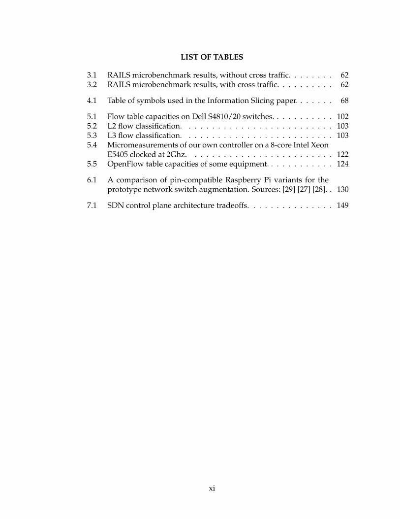
LIST OF TABLES
3.1 RAILS microbenchmark results, without cross traffic. . . . . . . . 623.2 RAILS microbenchmark results, with cross traffic. . . . . . . . . . 62
4.1 Table of symbols used in the Information Slicing paper. . . . . . . 68
5.1 Flow table capacities on Dell S4810/20 switches. . . . . . . . . . . 1025.2 L2 flow classification. . . . . . . . . . . . . . . . . . . . . . . . . . 1035.3 L3 flow classification. . . . . . . . . . . . . . . . . . . . . . . . . . 1035.4 Micromeasurements of our own controller on a 8-core Intel Xeon
E5405 clocked at 2Ghz. . . . . . . . . . . . . . . . . . . . . . . . . 1225.5 OpenFlow table capacities of some equipment. . . . . . . . . . . . 124
6.1 A comparison of pin-compatible Raspberry Pi variants for theprototype network switch augmentation. Sources: [29] [27] [28]. . 130
7.1 SDN control plane architecture tradeoffs. . . . . . . . . . . . . . . 149
xi

LIST OF FIGURES
3.1 OpenFlow-only switches require a communication primitivethat will not be forwarded by regular switches. . . . . . . . . . . 41
3.2 Example of an Ironstack deployment. Thick lines represent span-ning tree links . . . . . . . . . . . . . . . . . . . . . . . . . . . . . . 42
3.3 The topology used in our evaluation. Bold lines represent span-ning tree links. . . . . . . . . . . . . . . . . . . . . . . . . . . . . . 54
4.1 Sample workflow in our Mininet setup. Arrows indicate themovement of protected flows. . . . . . . . . . . . . . . . . . . . . 83
4.2 Network topologies simulated for our experiments. . . . . . . . . 844.3 Throughput of confidentiality service using varying message
sizes and topologies. . . . . . . . . . . . . . . . . . . . . . . . . . . 844.4 Throughput of anonymity service using varying message sizes
and topologies. . . . . . . . . . . . . . . . . . . . . . . . . . . . . . 844.5 Forwarding graph establishment time for anonymity service
with varying number of switches and paths in graph. Sincegraph establishment occurs only once to send many subsequentanonymous messages, millisecond setup times are acceptable. . . 85
4.6 Throughput of confidentiality service in different simulated net-works when varying the redundancy-to-confidentiality tradeoff(varying d’ wrt d). The fraction of slices required for reconstruc-tion is equivalent to the number of information slices that mustbe received (or intercepted) in order to reconstruct the originalmessage, divided by the total number of information slices sentby the NPU. . . . . . . . . . . . . . . . . . . . . . . . . . . . . . . . 85
5.1 Topology of the Gates Hall SDN. . . . . . . . . . . . . . . . . . . . 915.2 Hierarchical controller design. Dotted lines represent network
links on the data plane; solid lines are links on the control net-work. Note that high-level controllers do not need to be con-nected to every low-level controller. High-level controllers mayalso run distributed coordination logic amongst themselves. . . . 109
5.3 Low speed data plane access via veth0, a custom device driver.Dotted lines represent links in the data plane. . . . . . . . . . . . 118
5.4 High speed data plane access via eth1, a secondary Ethernet in-terface. . . . . . . . . . . . . . . . . . . . . . . . . . . . . . . . . . . 120
6.1 Schematic for the network switch augmentation, including con-nections to the OpenFlow switch. . . . . . . . . . . . . . . . . . . 131
6.2 A low priority rule captures all flow-miss packets and redirectsthem through a data plane port to eth1 on the switch augmenta-tion. If VLANs are used on the switch, this data plane port mustbe a tagged member of all such VLANs. . . . . . . . . . . . . . . . 133
xii

6.3 Flow miss packets are forwarded to eth1 on the switch augmen-tation and demultiplexed to the appropriate low-level controllerinstance. . . . . . . . . . . . . . . . . . . . . . . . . . . . . . . . . . 134
6.4 The serial configurator process provides arbitration, notificationand mediation for actual OpenFlow hardware settings. . . . . . . 135
6.5 An array of NetFPGAs using shared I2C communication lines. . 137
7.1 Ironstack components. . . . . . . . . . . . . . . . . . . . . . . . . . 1407.2 HAL processing pipeline. Dotted boxes represent processing
boundaries of the various HAL threads. . . . . . . . . . . . . . . . 1437.3 Packet callback chain. . . . . . . . . . . . . . . . . . . . . . . . . . 1447.4 An SDN with a separate control plane network. Control plane
elements are shaded in gray. One OpenFlow switch has beenmagnified for clarity. . . . . . . . . . . . . . . . . . . . . . . . . . . 147
xiii

CHAPTER 1
INTRODUCTION
The Internet-of-Things (IoT) refers to a recent trend towards the increasing per-
vasiveness of network connectivity in everyday devices, and is part of a contin-
uing evolution in the automation of everyday tasks. We see examples of these
cyber-physical technologies at work in familiar places such as Wifi-enabled TVs,
Internet-capable thermostats, network-controlled light bulbs and home security
solutions, but the same underlying technology also drives industrial-scale ap-
plications such as smart grids, smart city lighting and intelligent traffic control.
IoT is rightfully referred to as the ”infrastructure of the information society” [18]
because the network of IoT sensors and actuators provide the requisite data that
form the foundation of any smart initiative.
Because of the implicit dependence of IoT on data networking, we started
our line of inquiry by asking ourselves the following question: what features
would a modern network need to provide in order to support the emerging
needs of today’s Internet-Of-Things (IoT) equipment? We were deeply troubled
by reports from users about insecure, poorly designed devices [10]. At the same
time, we recognize that IoT device demands on bandwidth and latency span
the full spectrum, and there is no one-size-fits-all solution that would uniformly
work across all applications.
This IoT dilemma is real. Sensors and actuators depend on data networks
for connectivity and large-scale coordination, yet the design of these devices
and networks lack the necessary performance, reliability and security that are
expected in these demanding settings. To illustrate some of these issues, we
1

find it instructive to begin with an example of a critical IoT data network – the
power grid.
1.1 Challenges in power grid data networks
Operators of the nationwide power grid use proprietary data networks to mon-
itor and manage their power distribution systems. These purpose-built, wide
area communication networks connect a complex array of equipment ranging
from Phasor Measurement Units (PMUs) to Supervisory Control And Data Ac-
quisition (SCADA) systems. Collectively, these components form part of an in-
tricate feedback system that ensures the stability of the power grid. In support
of this mission, the operational requirements of these networks mandate high
performance, reliability, and security.
Present power grid data networks are predominantly run using microwave
relays and signal multiplexing on power cables. Connecting to the data center
network, a typical power grid operator would have a collection of data collec-
tion devices and relay status monitoring devices that have proprietary point to
point connectivity to some form of relay device hosted within the data center.
Thus the overall architecture has a set of these ”star” networks, using solutions
such as line-of-sight relaying over microwave, specialized communication pro-
tocols that run directly on the power lines, etc, that then link into the command
center networking infrastructure, with the relay devices functioning as proxies.
Although these technologies have proven acceptable over time, the growth of
big data in this coming age of smart grid systems means that existing capacity
2

on these data links could be rapidly saturated in the near future. A new and
better network technology is needed.
1.2 Evolving the Power Grid
1.2.1 Deficiencies in today’s power grid
Much of the national power grid is dependent on a relatively rigid, older style of
data networks for command, communications and control (C3). These data net-
works frequently carry critical information pertaining to the health of the grid,
often through sensor readings, that are then used to make decisions for the next
stable operating state of the grid. However, a chicken-and-egg cyclic depen-
dency exists between the two: a data network cannot survive without power;
conversely, without data, the grid cannot operate in a safe and stable manner.
As a consequence, a very rigid, heavily provisioned, heavily protected network-
ing model has emerged, in which today’s systems operate over a network that is
controlled in a very static manner. An increasingly wide range of features stan-
dard in other settings (such as dynamic assignment of host IP addresses) are
rejected by power systems operators, and the application layer functionalities
such features enable are thus not available.
A further issue is that to a growing extent, OS upgrades and patches have
made such features obligatory, hence power systems control networks are be-
coming costly to support because of their outmoded styles of use of technology.
3

Apart from physical infrastructure attacks, one of the weakest links in this
delicate balancing act is the data network and the software that depend on it.
There is emerging consensus that the power grid has numerous vulnerabilities
and is susceptible to large scale remote cyberattacks that can result in real, crip-
pling infrastructural damages. As an example, Stuxnet [62] is a well-known
malware that quickly spread through data networks and was directly responsi-
ble for the destruction of about 1000 nuclear enrichment centrifuges in Iran. It
is conceivable that a similar attack could be launched against power grid hard-
ware in the US, with devastating physical and economic effects. Thus, a design
objective of future data networks for the power grid should account for secu-
rity, with a focus on being able to precisely control and audit access to sensitive
equipment. Our chapter on EtherSlice investigates security solutions that are
relevant in this domain.
Another problem in the concurrent use of data networks to support grid
operations is the inherent risk of critical data flow disruptions during network
equipment outages. Such failures can occur for many reasons, including wear-
and-tear, accidents and uncorrelated power losses. Without access to current
data, grid operators are at risk for a cascading chain of failures. This is an im-
portant problem that future power grid networks should address, and we tackle
this issue in our chapter on RAILS.
1.2.2 Convergence of big energy and big data
Among other characteristics, a smart grid uses digital feedback control to re-
alize improvements and optimizations to the reliability and efficiency of the
4

power distribution network. Part of this smart initiative involves incorporat-
ing advanced electrical generation and storage technologies such as renewables
and batteries, but the ability to engage in real-time metering and command of
equipment is also another key requirement.
Thus, with the emergence of the next generation smart grid, the amount of
data that is expected to flow and be processed at control stations will sharply
increase. Cisco’s surveys [30] have shown that nearly one in four IT managers
expect network load to triple over the next two years; the power grid is no ex-
ception. In fact, the vision of a smart grid learning, adapting, and controlling
the power grid will require big increases in real time data transmission and net-
work load. However, current power grid communications infrastructure uses
antiquated technology that will need to be overhauled in order to support such
an increase.
Part of the need to support a higher network load comes from the emerging
use of Phasor Measurement Units (PMUs), which are sensors designed to mea-
sure real-time electrical current, voltage and frequency attributes at distributed
locations across the grid. Each of the phasor measurement units timestamps the
data that it receives before sending them off to a local Supervisory Control And
Data Acquisition (SCADA) system. Time-stamping these measurements allows
administrators to have a global view and understanding of the activities on in
the grid. Each such device generates 10kb/s or more data, with stringent la-
tency requirements on the links that forward these data to the control centers.
As the number of PMUs in the power grid increases, so will real-time data and
the need for strong and consistent reliability in the network which is difficult to
scale in the current infrastructure.
5

1.3 Design goals for a next generation power network
The smart elements comprising the power grid is the sum of many intercon-
nected components: meters, sensors, actuators, SCADA systems and opera-
tors, all generating or consuming real-time data off a data network in order to
provide intelligent behavior. Thus, acknowledging that the smart grid is data-
intensive, sensitive to correctness and heavily reliant on a responsive data net-
work, a clear set of design targets emerges: a next generation power network
needs to offer high performance, high assurance and high security. Also im-
portant, though to a less critical degree, are the pragmatic economic consider-
ations. Ideally, any proposed solution should be incrementally deployable and
fully backward-compatible with existing hardware and software on the power
grid.
1.4 Thesis contributions
The issues highlighted in the preceding sections are all seen in the smart grid,
but are actually universal: they arise to an equal or even greater degree in a
modern office complex, an academic campus setting, in a military base, or in
almost any environment where a data network might be of interest.
How then can a IoT smart initiative provide security and with high perfor-
mance leverage sensor deployments that depart from the historical infrastruc-
ture standards of the community? Our key insight here is that there are many
more IoT devices than there are switching elements in a data network, and it
is impractical to require IoT equipment vendors to rearchitect their devices for
6

improved experience. Thus, our model of how IoT becomes smart involves in-
novation at the level of deployment of such devices, but also in the ways the
existing network is managed and perhaps modestly enhanced. Our approach is
to pair the sensor with modern functionalities provided by a software-defined
network (SDN) that compensate for the sensor (and actuator) limitations. In
chapter 3, we describe RAILS, a system that draws on the classic storage coding
techniques from RAID [76] and applies these to data networks to transparently
improve the performance and reliability of IoT devices over Ethernet networks,
without requiring change or modification to the hardware or software of such
devices. RAILS was accepted for publication in IEEE SDN-IoT 2016.
RAILS leverages the deployment of an SDN with redundant paths, and also
depends on the strategic placement of packet processing elements known as
NPUs. This combination provides the necessary infrastructure to retrofit per-
formance and reliability for IoT devices, but does not address security. Security
has become a significant issue in modern data networks as users increasingly
demand confidentiality and often anonymity in their communications. Confi-
dentiality and anonymity are not merely pertinent as human factors in the post
Snowden era, but also represent important building blocks upon which a ro-
bust and resilient distributed system can be built. Many power grid sensors
and actuators, as well as IoT devices today [11] transmit data in the clear with
little regard for the potential consequences. While awareness of such security
issues are beginning to percolate equipment owners, there remains an urgent
need to address the issues of older hardware that were not designed to meet
newer security expectations.
7

Yet, a clean-slate upgrade of all affected IoT devices is unrealistic because
of the staggering time and monetary costs involved. Furthermore, the tradi-
tional route of retrofitting security through encryption typically requires public
key infrastructure and fails to address anonymity needs. We asked ourselves
if we could reuse the same network assumptions and NPU infrastructure de-
signed for RAILS to retrofit confidentiality and anonymity for IoT devices, again
without change or modification to end-user devices. The result was EtherSlice,
which is described in chapter 4. EtherSlice transparently provides security to
network devices while avoiding dependence on encryption, public key infras-
tructure or even awareness in the protected devices. We are presently working
towards a paper submission for EtherSlice.
With prototype systems in hand to address the performance, reliability and
security of IoT deployments, the next question that we considered was the prac-
ticality of setting up and running an SDN that could be used to drive RAILS
or EtherSlice. Indeed, in any kind of data network that might desire RAILS or
EtherSlice service, the fundamental assumption was that an SDN would already
be in place. What are the factors that could influence a power grid operator to
upgrade his data network to something that was RAILS and EtherSlice-ready?
Is the deployment of an SDN a simple matter of plug-and-play? Are there spe-
cial issues that arise that are not seen in traditional data networks? Chapter 5
details our operational experience in deploying an enterprise SDN from scratch,
and chronicles some surprising lessons we learnt about SDN and certain con-
trollers. We then incorporate these lessons into the design of our own SDN
controller, Ironstack, that mitigate some of the shortcomings inherent to SDNs.
We shared a summary of our findings in DSN’s DISN 2016.
8

Finally, we sought to close the loop by considering how we could offer all
three systems – RAILS, EtherSlice and Ironstack – in a unified turnkey solu-
tion that can be deployed quickly. We reasoned that a drop-in box packaging
these systems could be designed as a plug-and-play augmentation to existing
SDN switches. We anticipate that the convenience and frustration-free nature
of our network switch augmentation would hold universal appeal to infrastruc-
ture owners operating or considering the operation of SDNs, which could be
the magic recipe to convince data network operators such as the power grid
to finally transition over. Chapter 6 describes this network switch augmenta-
tion, highlighting the technical and engineering details of putting together these
three systems into a single box.
A summary of the thesis contributions are as follows:
• We identify IoT support over data networks as a critical concern in the near
future. Present-day IoT data networks are far from suitable for the task. As
a challenging example of IoTs, we surveyed performance, assurance and
security issues in power grid data networks and identify key objectives for
an SDN controller running such a network. Our high-level survey results
were published in ToSG 2014, and provided the direction for our research.
• We note that the network offers the most practical route to retrofitting per-
formance, assurance and security for Ethernet devices. This leads us to
identify network path redundancy, security and performance objectives,
and to suggest that an SDN could respond to the needs if properly config-
ured. We introduce two systems:
– RAILS, a set of novel network coding techniques adapted from
RAID, to transparently improve performance and reliability of net-
9

work clients. RAILS was published in IEEE NetSoft SDN-IoT 2016.
A working RAILS solution would be capable of breaking through
present limitations of single path routing to offer improved band-
width and resilience against network failure.
– EtherSlice, another set of network coding techniques adapted from
Information Slicing, to retrofit confidentiality and anonymity onto
Ethernet clients without requiring public key infrastructure. A de-
ployment of EtherSlice could secure devices that are vulnerable to-
day. We are currently working towards a submission on EtherSlice.
• We recognize that a healthy, configurable and user-friendly SDN is a crit-
ical prerequisite to deploying RAILS and EtherSlice. This motivates us to
investigate the practical issues relevant to the construction, configuration
and operation of an SDN, as well as to characterize the performance of a
few popular OpenFlow SDN controllers. We detail two major findings:
– We uncover some surprising findings from our deployment experi-
ence and identify several key challenges to adopting OpenFlow in an
enterprise setting. For each finding, we propose one recommenda-
tion to mitigate the overall impact of these surprises.
– We survey two OpenFlow SDN controllers and observe that they are
slow, buggy and not user-friendly. This motivates us to build and
validate Ironstack, a controller that addresses the weaknesses of these
SDN controllers.
Our findings and recommendations were published in IEEE DSN DISN
2016.
10

• We consider the utility of a unified solution containing RAILS, EtherSlice
and Ironstack. This inspires us to design and implement an OpenFlow
network switch augmentation that packages all three aforementioned sys-
tems into one unified hardware, while remaining convenient and user-
friendly. This unified turnkey solution would be an attractive product for
managing SDN-based IoT networks that also require RAILS or EtherSlice.
• We draw on our operational experience and examine the challenges of
building an SDN controller that provides adequate performance, scalabil-
ity and user-friendliness. We architect a distributed OpenFlow controller,
Ironstack, to provide these features, and disclose its software component
design and highlight its critical features. We also compare and contrast
the various ways in which the control plane network can be built, and
describe how our controller can adapt to these designs.
11

CHAPTER 2
BACKGROUND AND RELATED WORK
Architecting a new kind of Ethernet data network to address problems intro-
duced by the limitations of existing networks and shortcomings of participatory
IoT devices is an involved task requiring deep understanding of the reasons for
these issues. Because our approach is to avoid change at the level of the IoT
devices, a transparent retrofit will require innovation at the networking layer.
In this chapter on background work, we first study the limitations inherent to
existing Ethernet networks, then look at how we may circumvent some of these
constraints through use of a new kind of programmable networking technol-
ogy. We also consider existing alternate approaches to tackling the same set of
constraints, and reason that existing approaches are insufficient for our goals.
From there, we draw inspiration from two main bodies of work accomplished
by others to derive a set of network coding schemes suitable for our purposes.
We then look at strategies to implement the required hardware and software
for these network coding schemes. Finally, we investigated numerous network
controller architectures in order to identify the most suitable analogue for our
needs, and co-design our own controller taking into consideration the unusual
lessons learnt by others from using comparable networking hardware.
2.1 Ethernet Spanning Tree
Ethernet has seen many adaptations since its creation in 1973, and has
evolved from a LAN-only networking solution to WAN and beyond. Its cost-
effectiveness, flexibility and scalability are the main factors contributing to its
12

popularity. Today, it is the favored link-layer medium for diverse applications
ranging from communication carriers to cloud providers to enterprises to regu-
lar users, and is projected to continue its evolution to embrace IoT standards in
the future [8]. Indeed, recent standards such as the IEEE1588 [17] point to this
trend, as they were specifically conceived to meet the timing precision require-
ments in demanding IoT applications over Ethernet.
Yet, conventional Ethernet is poorly matched to our goal of providing a
multipath-capable network for RAILS and EtherSlice because it has an impor-
tant restriction that mandates a spanning tree topology for correct operation.
This spanning tree requirement is not arbitrary; it was designed to connect all
participating hosts while eliminating catastrophic network loops. Conventional
Ethernet networks perform loop elimination and spanning tree construction by
running a distributed algorithm such as the Spanning Tree Protocol (STP) or
the improved Rapid Spanning Tree Protocol (RSTP) [14]. In STP and RSTP, Eth-
ernet switches in the same network segment collaborate and agree on which
network links to use such that a single spanning tree connects the entire net-
work without any cycles. In the process, STP or RSTP disables links that would
otherwise result in loops. All traffic transits the spanning tree, which becomes a
network-wide bottleneck. Accordingly, conventional Ethernet networks do not
typically feature link redundancies, and where such redundancies exist, they
cannot be taken advantage of without special configuration. Worse, failure re-
covery and redundant link activation typically take between several seconds to
half a minute [31], resulting in network hiccups even if no apparent physical
partitions have been introduced.
13

To remove the limitations imposed by a single spanning tree, RSTP was ex-
tended to the Multiple Spanning Tree Protocol (MSTP) [15]. MSTP allows con-
current multiple spanning trees to exist within the same network by mapping
each spanning tree to a multiple spanning tree instance (MSTI). Each virtual
LAN in the network can then be associated with one of the spanning tree in-
stances, thus improving aggregate network availability and reliability when link
breakages happen. Bottlenecks are also reduced because the network now dis-
tributes its load over a greater number of transit links. However, within an
MSTI, participants are still subject to spanning tree outages and repair time.
Thus while some VLANs may experience little disruption, other VLANs may
be severely impacted. This can seem counterintuitive especially if redundant
physical paths do exist in the network and no actual physical partitioning was
caused.
Because of the futility in using non-tree topologies, conventional Ethernet
networks are infrequently architected with link redundancies, and where such
redundancies exist, they cannot be taken advantage of without special config-
uration. We feel that this is at odds with the plug-and-play vision of Ethernet,
where it might intuitively have been expected that additional links introduced
between network switching elements should have the effect of automatically
and transparently increasing redundancy and performance. Without substan-
tial planning and complex manual configuration, redundant links are typically
left unused until primary failures force them into action. Worse, failure recov-
ery and redundant link activation typically take between several seconds to half
a minute [31], resulting in network hiccups even if no apparent physical parti-
tions have been introduced.
14
2.2 Software-Defined Networking
To work around the spanning tree restrictions imposed by Ethernet spanning
tree, we use software-defined networking (SDN). SDN is a modern abstraction
that allows access to a network switch’s routing fabric. In SDN models, the
switch’s control plane is accessible to an external entity known as a controller,
to which all data forwarding decisions are delegated. This control plane has
complete command of the data plane, where network packets are transferred
between physical and virtual ports on the switch. The control plane is also able
to introspect the operational parameters of the data plane, and has a limited
capability to transfer packets between the data plane and the control plane at
will.
Among SDN standards available today, OpenFlow [68] is the most widely
supported specification and is the bedrock upon which our work rests on.
OpenFlow is managed by the Open Networking Foundation and has seen sig-
nificant evolution through multiple versions. The most recent version of Open-
Flow is 1.5 [74], although many switches marketed as OpenFlow-capable to-
day support only OpenFlow 1.0. Successive versions of the standard have in-
creased complexity and are not backward-compatible, necessitating indepen-
dent firmware support for each version of the standard that a switch hardware
supports.
On the software end, there are multiple efforts to develop operational Open-
Flow controllers, each with varying degrees of programmability, complexity
and performance. Some popular controllers include the open-source POX [26]
(a generic Python-based system), Floodlight [9] (Java-based), OpenDaylight
15

[23] and ovs-controller [22] (a C-based reference controller written by Open
vSwitch). Commercial closed-source controllers include the Ericsson SDN con-
troller [7] (derived from OpenDaylight), NEC’s ProgrammableFlow Controller
PF6800 [20] and Big Switch’s Big Network Controller [2]. Distributed con-
trollers, such as Onix [58], ONOS [34] and Ravana [54] have also recently be-
come available. The latter few served as principal references for our own dis-
tributed controller design, while our experience with some of the former have
inspired us to incorporate usability improvements of our own.
2.3 Multipath networking techniques
Our RAILS work depends on multiple disjoint paths to deliver performance and
reliability. Multiple paths can be provisioned by OpenFlow SDN techniques.
However, before considering the use of SDN, our first inclination was to look
into literature for examples where multipath networking is used to accomplish
similar improvements. Many multipath networking solutions are variants of a
theme designed to reactively address failure through the computation of some
backup topology or topologies. For example, Path Splicing [70] is a mecha-
nism that provides multiple paths through a network through the use of mul-
tiple statically predetermined routing trees. By allowing traffic to switch rout-
ing trees at each forwarding node, the system ensures path reliability during
outages, where disjoint path routing may fail. Path splicing has fast recovery
time but flows are not redundantly routed and it experiences latency stretch
as data traverse non-optimal routes. As a result, the system is able to com-
pensate for failure relatively cheaply, but trades off some performance in the
process. By comparison, RAILS is proactive and simultaneously addresses both
16

performance and reliability. In fact, the selection of an appropriate RAIL scheme
can simultaneously compensate for failure while also offering performance im-
provement.
Another example of a reactive, pre-provisioned approach is Multiple Topolo-
gies for IP-only Protection Against Network Failures [33]. This solution de-
scribes the use of multiple topologies for transparent routing recovery and fault
tolerance. Routers precompute some backup topologies and reroutes packets
along the backup paths in the event of failures. It performs very well in realistic
scenarios even though IP traffic only take single routes at any instance. Again,
the approach here is reactive and designed to address failure only. Furthermore,
it is an IP-only solution, whereas RAILS is capable of providing performance
and assurance for more general classes of traffic as long as they run over Ether-
net.
An interesting and pre-provisioned approach is CORONET [56]. CORONET
computes link-disjoint paths, similar to RAILS, and implements each disjoint
path as a different VLAN. Similar to our network switch augmentation, CORO-
NET also implements a switch configuration module that sets up VLANs. It
has a traffic assignment module that assigns host traffic to the VLANs. Thus,
instead of relying on point-to-point OpenFlow rules, CORONET uses VLANs
to specify paths, and it is claimed to be faster for packet forwarding and failure
detection. However, CORONET lacks an evaluation section and it is not clear if
the VLAN method of assigning paths is scalable since only 4094 VLAN tags are
available.
Other approaches are topology-agnostic and depend on other assumptions
for multipath data transport. For example, Multipath TCP [45] works on the L3
17

network layer and assumes that each IP address owned by the host is homed on
a distinct network. The protocol takes a stream of data and distributes it across
the multiple owned IP addresses, in the hopes that the underlying physical com-
munication paths taken by each subflow to the destination are actually distinct.
This assumption works well in applications such as smartphones, which can
leverage both Wifi and over-the-air networks as truly disjoint paths. However
over Ethernet deployments, this assumption is less dependable because MPTCP
transport over an Ethernet spanning tree could cause subflows to tunnel over
the same L2 physical layer links. In comparison, RAILS uses physical network
topology information in order to construct truly disjoint network paths.
However, assuming path disjointness exist in a given MPTCP use case,
MPTCP enjoys the cost convenience of not needing any modifications on the
existing network. However it does require multihoming on devices that wish
to take advantage of it. Multihoming may not be possible on many devices that
cannot be outfitted with a second network interface card. Furthermore, support
for MPTCP is sparse [59] at present, and only caters to the TCP protocol.
Various Ethernet-based multipath or multipath-like approaches also exist.
For example, STAR [65] is a spanning tree-compatible protocol that improves
QoS routing in an extended LAN. Packets are forwarded over the spanning tree
by default but may also take shorter, non-spanning tree alternate paths where
they are available. However, unlike RAILS, STAR was developed as a QoS so-
lution, and was not designed to handle failure. Hedera [32] is an example of a
dynamic flow scheduler that actively schedules multi-stage switching fabrics in
order to improve bisectional bandwidth. It works by collecting flow informa-
18

tion from all constituent network switches and maintaining a global view of the
network in order to intelligently re-route traffic around bottlenecks.
Reactive, pre-provisioned Ethernet analogues of IP-based multipath also ex-
ist, and are somewhat closer to RAILS in terms of their offerings. SPAIN [71] is
an Ethernet-based solution that implements redundancy by mapping strategi-
cally computed paths to separate VLANs. SPAIN provides increased bisection
bandwidth and resistance to network failures. However, its implementation
relies on static, pre-installed paths, and does not adapt to substantial network
topology changes. Unlike RAILS, SPAIN does not offer a continuum of laten-
cy/bandwidth tradeoffs.
Similarly, ECMP [16] is a load-balancing routing strategy that can take ad-
vantage of redundancies in a network. Under ECMP, each flow is hashed to a
single path from a set of available paths. Although each flow transits only a
single path, the aggregate effect is to spread distinct flows across all the avail-
able paths, thus load-balancing disjoint paths as a whole. However, because
each flow only still uses a single path, individual flows are subject to disruption
should a link in their paths fail.
802.1 Ethernet link aggregation [13] combines several physically distinct net-
work links on a switch into a single large logical link, which makes it a special
case of RAIL 0. With appropriate failover recovery, Ethernet link aggregation
can also improve the resilience of the network against individual link failures.
However, only two switching elements may participate in each aggregated link.
When a participant switch fails, the entire aggregated link also fails. This is in
contrast to RAIL 0, where the link aggregation is the result of multiple paths
19

across multiple switches. If a switch fails in RAIL 0, the aggregated link can
continue to exist with reduced bandwidth.
Finally, there are network virtualization techniques that can be used to pro-
vision multiple paths. In virtual network embedding services, multipath net-
working can be elegantly and efficiently provisioned by the underlying sub-
strate. A network virtualization manager presents the view of virtual nodes
and logical network links, while the virtualization service manages the map-
ping of virtual to physical resources. This mapping can aggregate multiple
physical links for a single virtual link, thus reaping the performance benefit
of having multiple network paths. Substrate Support for Path Splitting and Mi-
gration [89] exploits this technique in network embedding, utilizing multiple
paths, load-balancing and dynamic path selection.
Although virtual network embedding presents a clean abstraction to net-
work users, it nonetheless passes the problem of multiple paths on to the vir-
tualization layer. At present, many techniques [89] [51] rely on flow hashing
to attain efficient use of the available substrate paths while avoiding the prob-
lem of packet reordering. Like ECMP, this again has the effect that a physical
link failure could disrupt certain flows while leaving others unaffected, and dis-
rupted flows could take substantial time to recover depending on the virtualiza-
tion manager. Finally, unlike RAILS, the full bandwidth across all the available
substrate paths cannot be realized.
SDN-based solutions for robust networking have also been examined. Fat-
Tire [77] is a programming language that allows users to specify network redun-
dancy levels, as well as the specific paths that their data packets should transit
in a network. The program is then efficiently compiled down to OpenFlow rules
20

that are installed on network switches. This approach naturally facilitates the
implementation of seamless network link failovers. However, it requires sub-
stantial domain-specific knowledge to operate and program in the language,
whereas RAILS is a simple solution that does not require much configuration.
Systems based on forward-error correction schemes similar to RAIL 1 and
RAIL 4 also exist. Redundant Packet Transmission (RPT) [48] is a system de-
signed to efficiently and proactively provision for network losses through a
content-aware network that contains redundancy eliminating routers. The ap-
proach is similar to RAIL scheme 1 in our work, although RPT does not utilize
multiple paths and was designed to withstand losses in a single path. RPT dif-
fers from forward error correction schemes in that it is more efficient; in the RPT
system each original packet in a stream is duplicated, however each duplicate
packet beyond the first is compressed or encoded by the RPT router. At each
hop of the RPT router, the packets are all decoded or decompressed, and then
subject to recompression again after packet drops have been allowed.
2.4 RAILS and RAID
The main body of work that inspired the RAILS system was based on RAID [76].
RAID [76] is the classic work that explores various techniques of storing data on
independent disks for the purpose of improving redundancy and performance.
Data storage using RAID is largely organized into standardized schemes, with
RAID0 corresponding to no redundancy (thus allowing the full utilization of
all independent disks), RAID1 corresponding to direct mirroring (simple repli-
cation of data across multiple disks) and higher RAID levels corresponding
21

to more complex parity-protected data striping methods. We conjectured that
there exists a parallel between independent disks in a RAID system and inde-
pendent network paths in an SDN, and explored the applicability of such net-
work coding schemes over an SDN. In so doing, we also looked at a number of
current multipath techniques.
We conjecture that a parallel exists between disks and network paths as data
mediums, so the performance and protection schemes deployed on disks are
also applicable in a network. RAID [76] is the classic work that explores various
techniques of storing data on a set of independent disks for the purpose of im-
proving redundancy and performance. Data storage using RAID is organized
into standardized schemes or levels, each scheme providing a different set of
benefits and tradeoffs.
In RAID 0, all constituent disks are aggregated into one large logical disk
without redundancy, at the risk of having no protection from failures. RAID
0 allows a user to treat the RAID array as one single large disk, and has the
benefit that the multiple read/write heads from the constituent disks can be
used to improve read and write efficiency. Similarly, in RAIL 0, the available
bandwidth from all constituent network paths are aggregated into one single
large logical pipe, which the user sees as a single network path. The individual
constituent paths contribute to improved throughput, but like RAID 0, the loss
of a single network path will cause the transmission scheme to fail.
On the other end of the efficiency/reliability continuum lies RAID 1. In
RAID 1, all data is mirrored across each of the independent disks so that the
array can suffer the loss of all but one disk, at the cost of drastically reducing
the overall storage efficiency. Similarly, in RAIL 1, network packets are dupli-
22

cated across every network path, greatly increasing the redundancy of the data,
at the cost of very high bandwidth.
RAID levels 2-5 are parity-based improvements upon RAID 0 and 1. The
ideas behind RAID 2-5 are similar in spirit. To improve storage efficiency, full
mirroring is not used; instead, some variant of forward parity protection is de-
ployed. This is compact and ensures that content can be reconstructed despite
the loss of any single disk. By being able to mask a single fault, the resiliency
of the disk array is improved against failure. The individual schemes vary only
in the granularity and placement of the parity blocks: RAID 2 (bit level parity),
RAID 3 (byte level parity), RAID 4 (block level parity) and RAID 5 (block level
parity with distributed parity). Because they are all variants on the same parity
theme, we implemented RAIL 4, which uses discrete network packets as disk
block analogues in RAID.
RAID 6 is essentially a refinement over RAID 5. By adding a second dis-
tributed parity block, the disk array can survive two failures instead of one. The
construction of the second parity block is substantially more complicated and
computationally expensive.
2.5 Network Security
An intelligent SDN controller built to coordinate RAILS and EtherSlice oper-
ations require some awareness of data plane network state. For example, an
SDN controller should know the bindings of device Ethernet addresses to IP
addresses. This knowledge allows the SDN controller to localize a resource, as
well as to detect misuse conditions such as IP address spoofing/squatting, ARP
23

poisoning attacks or rogue DHCP attacks. A forward-looking implementation
of an SDN controller may even use this knowledge to improve network per-
formance. For example, EtherProxy [44] suppresses network-wide broadcasts
when its middleboxes are able to answer DHCP or ARP queries. Ethane [36]
extensively uses such knowledge of network state to enforce security policies.
Similarly, we use knowledge of the data plane network state to guard against
Ethernet address spoofing, ARP poisoning and rogue DHCP attacks in our im-
plementation of EtherSlice.
Many anonymizers are based on Chaum mixes [38], which is public-key
encryption-based. In Chaum mixes, a sender constructs a path to the destination
through a number of anonymizing hops, and encodes this path using layered
cryptography. At each hop, the node decrypts its next forwarding destination,
but has no knowledge of other hops or the penultimate source and destination.
Nodes also arbitrarily delay or reorder output messages. Anonymizers based on
Chaum mixes include popular onion routers such as Tarzan [46], Vuvuzela [85]
and Tor [41]. Many of these systems are low-latency, but susceptible to traffic
analysis and correlation attacks.
Other variant anonymizer systems are based on Chaum’s Dining Cryp-
tographers network (DC-net) [37], which are resistant to traffic analysis, but
rely on the construction of a bandwidth-heavy anonymous broadcast channel.
These anonymizers provide resistance to traffic analysis by using fixed-length
encrypted messages released at time epochs, which remove temporal correla-
tions of transiting messages at the cost of being non-realtime. Systems that
improve on the scalability of DC-nets include Herbivore [47], Riposte [39] and
Dissent [87].
24

2.6 Network Processing Units
An OpenFlow SDN featuring multiple paths is one part of the requirement to
support RAILS and EtherSlice, since it allows precise control over packet for-
warding paths. However OpenFlow itself does not provide facilities to mod-
ify packets in arbitrary ways. Recall again that our fundamental operating as-
sumption for IoT devices on our network is that they should not require any
change or modification in their hardware or software. Thus, to support RAILS
or EtherSlice, packets need to be modified elsewhere other than on the devices
and switches themselves. For this purpose, we use Network Processing Units
(NPUs).
Network Processing Units (NPUs) are general-purpose packet processors
that can arbitrarily modify network datagrams. Technologies such as Open-
Flow and P4 [35] support some limited form of packet modification, but they
are not truly general in that their modification capabilities are restricted to only
the packet header and not to the rest of the packet body. NPUs can be realized
in either software or hardware.
On the software end, Marinos et al. [67] proposed an aggressive optimiza-
tion for certain network applications (such as DNS and static HTTP content
servers) by compressing the network stack itself, essentially bypassing latencies
that are otherwise introduced by the usual network layers. Their implementa-
tion leveraged Netmap [78] to provide low-latency access to network packets
in userspace. They then built their own custom Ethernet, TCP/IP and UDP/IP
layers to provide socket-like services without incurring substantial system over-
25

head. This is far superior to our initial libpcap approach, and motivated us to
try Netmap.
The Netmap [78] provides fast packet I/O that uses various optimizations
such as batching and ring buffers to map (hence its name) packets from the NIC
directly to user space. Netmap provides very high packet throughput, and by
the authors’ accounts, were able to sustain line rate packet counting at 10Gb NIC
speeds using a modest CPU. Our experience was a little mixed with Netmap as
we were not able to attain the same levels of performance on our hardware.
Furthermore, our implementation of the RAILS and EtherSlice NPUs required
more than just packet counting or header inspection; because of the computa-
tion inherent to our work, we were unable to sustain the necessary bandwidth
for operation on a dedicated x86 CPU. DPDK [4] and PF RING [25] are other in-
dustrial software alternatives to Netmap that also provide fast direct userspace
access to network data packets by bypassing the kernel network stack.
NetSlice [66] is an operating system API that provides line speed (10Gbps)
access to network packets through a specialized network stack that is back-
ward compatible with existing socket APIs. NetSlice attains high performance
by leveraging dedicated CPU cores, memory and NICs for packet processing,
and also uses optimizations such as I/O batching to reduce the cost incurred at
kernel traps.
Mekky et al. [69] proposed an extension to Openvswitch that allows
application-level packet processing to be efficiently accomplished in the data
plane of a software switch, such that they avoid the lengthy detours that
application-level packets sometimes take to reach the controller and later reen-
ter the data plane. They do this by intercepting packets before they arrive at
26

Openvswitch, and were able to demonstrate several network functions imple-
mented in this way. Our implementation of EtherSlice uses the PACKET IN
method of receiving packets from Openvswitch, and would have benefited from
this method of direct processing in the data plane.
SoftNIC [49] is a hybrid software-hardware system that allows high perfor-
mance programmability of NIC-like features in software, as opposed to hard-
ware. For example, protocol offloading, packet classification, rate limiting and
virtualization, as well as new protocols can be supported. SoftNIC accomplishes
this by creating a shim layer between the NIC hardware and network stack, and
processes packets in a pipeline using dedicated compute cores. The system is
backward compatible.
P4 [35] provides a generalization of the OpenFlow match/action processing
by proposing an expressive packet parser that is independent of protocol sup-
port baked into the hardware. However, because P4 implementations buffer
the packet body separately, they are unable to perform payload-modification
operations such as those required to support RAILS or EtherSlice.
The Click Modular Router [57] is a flexible and extensible software architec-
ture to add functionality to routers. At its core, it is a software-driven router,
with packets flowing between functional elements in a pipeline. These func-
tional elements are written in C++ and can be tailored to provide standards-
compliant routing service, or in fact any arbitrary custom packet processing.
Thus the system can be likened to a very early implementation of an NPU.
On the hardware end, Split SDN Data Plane (SSDP) architectures [72] and
loadable packet processing modules [73] offer industrial-performance alterna-
27

tives to the FPGA designs, by integrating the packet processing requirements
into an alternate data path that is directly connected to a switch co-processor.
The NetFPGA [21] series of hardware cards provide a development platform
for designing, prototyping and testing hardware-based NPUs. FPGA-based
NPU designs offer the performance of raw hardware without operating sys-
tem overhead, and can be designed with traditional hardware synthesis tools.
An FPGA implementation of an NPU has the advantage that specialized hard-
ware (such as multiple functional units, parallel computation cores, dedicated
packet buffers, etc) can be realized with very low latency. This was the method
we chose for building RAILS.
More commodity hardware NPUs include PacketShader [50], which uses off-
the-shelf GPUs to implement generic packet-processing functionalities on a reg-
ular desktop computer. In PacketShader, network datagrams are moved from
the network interface over to the GPU, where a custom shader program per-
forms the required transformations to realize a specific NPU functionality. Be-
cause GPUs have many streaming multiprocessors optimized for parallel com-
putation and are better able to cope with the memory access patterns of network
packet processing, they perform very well for payload modification tasks that
are traditionally taxing on regular x86 processors.
2.7 Controller Design
In building our own OpenFlow controller from scratch, we referenced other
designs and sought to incorporate some of the benefits of their approaches.
28

Google’s B4 [53] is an OpenFlow controller used to drive their internal wide
area network. The goal of their controller was primarily traffic engineering;
they were able to improve inter-datacenter network link utilization from 30-
40% to almost full utilization. Although traffic engineering was not a primary
goal of our Ironstack controller, the Google B4 deployment informed our con-
troller design and we were able to verify some of the lessons they described. For
example, the B4 work noted that the connection between the OFC (OpenFlow
controller) and the OFAs (OpenFlow agents, which reside on the switches) were
the most constrained and it affected packet IO rates. Their proposed improve-
ment suggested that two channels might be necessary: one for packet IO and
another for other control traffic such as link status change and switch program-
ming operations. We took this suggestion and implemented a separate channel
for PACKET IN traffic, while retaining complete compatibility with OpenFlow.
This is examined in more detail in chapter 6.2.2.
Another feature we drew from Google’s B4 and Ethane [36] was the ability
for data plane applications to communicate directly with the control plane. This
feature is missing from many OpenFlow controllers today. We believe this to
be useful as it allows data plane applications to influence controller decisions.
For example, Ethane directs network users to authenticate with the controller
through a web form before installing appropriate flow rules to bypass the cap-
tive portal. B4’s Routing Application Proxy (RPA) bridges packets from their
Quagga control plane and the switch’s data plane. Our RAILS and EtherSlice
controllers use this ability to communicate with data plane users for negotiat-
ing flow enhancement services. The Ironstack system also uses this feature to
implement a simple echo server on the low-level controllers; it is used for mon-
itoring controller liveness from the data plane. The mechanics of bridging the
29

control and data planes vary, but we present two possible implementations in
section 5.6.4.
Our experience with centralized SDN controllers show that they perform
poorly under load and during initialization. This is in line with our predictions
from distributed systems. As a result, we looked for alternatives to central-
ized SDN controller designs. Onix [58] uses a distributed, replicated network
information base (NIB) to improve the scalability, reliability and resilience of
network control applications. These network control applications specify their
needs for consistency, performance, durability and scalability to Onix. Onix
uses a one-hop, eventually consistent, in-memory DHT to store network state.
State inconsistency is possible in this system, and it is up to the network control
applications to resolve these on their own.
Onix [58] is one of the earliest implementations of a distributed SDN con-
troller. The Onix system is scalable, fault tolerant and has high control plane
performance on the basis of its distributed architecture. Yet it is logically cen-
tralized, allowing control applications to use a single control platform to imple-
ment a range of control functions (such as traffic engineering, routing and ac-
cess control) in a simple manner. Onix uses a transactional persistent database
backed by a replicated state machine for disseminating Network Information
Base (NIB) state updates among the distributed Onix instances. However, Onix
depends on the control application’s assistance to specify consistency require-
ments, such as the need to prioritize responsiveness over consistency, or vice
versa. We note that many control applications can tolerate eventual consistency,
and implemented our controllers using a gossip mechanism; an advantage of
30

our gossip mechanism is that our controller does not need to rely on a costly
separate control network.
ONOS [34], a distributed network operating system inspired by Onix, uses
multiple running instances to manage a large network. Several OpenFlow
switches may map to one ONOS instance, and as the network scales, more
ONOS instances can be started to manage the load. ONOS provides a logically
centralized view of the global network state using a distributed data store. Its
final implementation uses RAMCloud [75] as its backing store, and it relies on a
publish/subscribe event notification model to exchange state changes between
its ONOS instances.
HyperFlow [84] is an implementation of a distributed OpenFlow controller.
It assumes a separate network that relies on WheelFS [81] to maintain consis-
tency. HyperFlow uses a publish/subscribe messaging system to synchronize
select state across multiple controllers. Each controllers subscribes to three mes-
sage channels: a data channel, a control channel and its own channel. These
channels are represented by directories and the messages are represented by
files. The job of managing network state consistency and partition tolerance is
delegated to WheelFS. To prevent network loops, flow paths are setup by an au-
thoritative controller, which is the controller managing the flow’s source switch.
Elasticon [42] is an elastic distributed OpenFlow controller architecture,
which allows for dynamic growth, shrinkage and load balancing of controller
instances according to instantaneous load. In Elasticon, an OpenFlow switch
connects to multiple SDN controllers. When the master of a switch needs to
be reassigned or migrated, an ingenious signalling method is used to provide
31

safety and liveness during a handover. A distributed data store is used to logi-
cally centralize data that is shared among all controllers.
A distributed SDN controller offers robustness and scalability, but it also in-
troduces consistency and ordering problems typical in a distributed system. We
found it insightful to learn from approaches to these problems. Ravana [54]
uses two phase replication protocols to improve on the distributed semantics of
control plane operations on an SDN. By introducing a controller runtime and
a switch runtime that buffers events into a totally ordered, in-memory log, the
system guarantees that events are processed exactly once and without loss. This
is a departure from other distributed controller approaches in that it correctly
handles state changes during failovers. Ravana also provides a transparent run-
time that insulates controller applications from the underlying distributed na-
ture of the system.
Before adopting a distributed approach for our controller, we also looked at
the specific impact of such a design on an SDN. Levin et al. [63] investigates
the various issues behind distributed SDN control architectures that are logi-
cally centralized. A logically centralized architecture retains tradeoffs from its
underlying dependence on distributed systems, and they identified two impor-
tant tradeoffs: between staleness and optimality, and between application logic
complexity and robustness to inconsistency. These tradeoffs are relevant to the
design of distributed SDN controllers because they affect an SDN application’s
performance, liveness, robustness and correctness.
32

2.8 SDN switch quirks
Our experience with quirks in our OpenFlow switches was initially surprising,
and suggest that others may have encountered similar issues in other settings.
We sought to characterize some of these issues to further enlighten our con-
troller and hardware augmentation design.
Kuzniar et al. [61] performed investigations on a number of OpenFlow
switches to characterize the interaction between the control plane and the data
plane. The authors uncovered a substantial amount of surprising behavior, in-
cluding temporal locality behavior in switch updates, performance degradation
caused by priority fields, non-atomic rule modifications on a switch and even
incorrect OpenFlow barrier behavior. Although their discoveries were made on
different switches, we noted some parallels with our hardware, and their work
supports our hypothesis that unexpected, standard-deviating behavior is a phe-
nomenon that should be taken seriously by developers.
DevoFlow [40] examines the various causes of latency inherent to OpenFlow
and describes the negative impact of flow table size and statistics collection on
OpenFlow performance. They then prescribe and verify more efficient methods
to install flows and gather statistics by minimizing interactions with the SDN
control plane. While their choice of OpenFlow hardware was different, our ex-
periences were largely similar. This reinforced our hypothesis that the abstrac-
tion between OpenFlow hardware and software is not clean and decoupled as
the specifications may suggest.
Given the heterogeneity of different hardware, we considered how we might
build a generic controller that would work well across multiple hardware. As a
33

first step towards this goal, we evaluated the possibility of starting with a ref-
erence switch implementation, and then tailoring the reference switch to sim-
ulate different hardware. The OFLOPS [79] framework recognizes diversity in
the performance and implementation of OpenFlow switch firmware, and char-
acterizes their behavior and performance under a variety of test cases. These
characteristics can be used to model switch behavior more accurately than test-
ing on reference implementations of OpenFlow, such as Open vSwitch [22]. In-
terestingly, their work also uncovered bugs in the implementation of barriers on
switches.
Similarly, Danny et al. [52] studied the similar problem of trying to emulate
specific vendor performance characteristics with respect to control path delays
and flow table usage. They were able to improve the accuracy of switch em-
ulation to a high degree of accuracy across multiple vendors. This work was
helpful for our goals since we wanted to build a controller that would work
on a variety of hardware platforms, even though we did not have access to the
various hardware ourselves.
Our concern about different performance across different hardware led us
to search the literature for unifying alternatives. NOSIX [88], an analogue of
the POSIX system standard, is a proposed solution to provide better standard-
ization across diverse OpenFlow switch hardware. The authors describe a uni-
form, portable abstraction layer for SDN controller development through the
use of virtual flow tables and vendor-provided switch drivers. Controller de-
velopers then specify their requirements for rule processing and make promises
about their usage of the virtual flow tables. Unfortunately, NOSIX is not cur-
34

rently in widespread use and few switch vendors have supplied their switch
drivers.
Because of the shortage in generic table space on our switches, we looked
at alternatives to bridge the gap. Lu et al. [64] describe an implementation of a
CPU as a network switch co-processor. They make the observation that mod-
ern processors have adequate computing power and have the benefit of access
to DRAM, and can thus augment switches with larger forwarding tables and
deeper packer buffers. Their system offloads a portion of a network switch’s
data plane load for processing on a CPU, which then relays the processed pack-
ets back to the switch ASIC.
Our experience with configuring and operating SDN switches in pre-
OpenFlow mode was tedious and laborious. Thus, while designing our network
switch augmentation, we looked into literature to see how others solved similar
problems. As it turns out, the problem of initializing and configuring a switch
for production use is unavoidably convoluted and manual labor-intensive. The
EtherProxy paper [44] echoes this same sentiment: VLANs and subnets need
to be created and configured, address assignments need to be managed and
routers connecting network segments need to be setup. The process is error-
prone and involves a lot of human interaction. Our experience is similar in this
aspect; we note from our time working with Cornell’s ITSG (Information Tech-
nology Support Group) that the setup and configuration phase for hardware is
tedious, laborious and often error-prone. In chapter 6, we discuss the design of
a serial configurator that takes over the burden of most initialization, allowing
an operator to rapidly deploy switches.
35

CHAPTER 3
RETROFITTING PERFORMANCE AND RELIABILITY OVER ETHERNET
Data networks require a high degree of performance and reliability as
mission-critical IoT deployments increasingly depend on them. Although per-
formance and fault tolerance can be individually addressed at all levels of the
networking stack, few solutions tackle these challenges in a scalable and easy
to configure manner. We propose a redundant array of independent network
links (RAILS), adapted from RAID, that combines software-defined networking,
disjoint network paths and selective packet processing to improve communica-
tions bandwidth and latency while simultaneously providing fault tolerance.
Our work shows that the implementation of such a system is feasible without
necessitating awareness or changes in the operating systems or hardware of IoT
and client devices.
3.1 Introduction
The potential uses of multiple paths in a network have attracted significant at-
tention, and many IETF standards [45] [86] have been finalized or are now being
finalized to expose and exploit these capabilities. The reasons for this interest
reflect multiple goals: multipath networking provides (1) improved resilience
to failures and (2) improved network load-balancing, leading to (3) better data
throughput, and hence improved user experience.
The basis for multipath networking is conceptually simple. Multipath net-
working can be seen as another form of parallelism, with the objective of im-
proving network performance subject to some underlying constraints. These
36

underlying constraints are highly varied, and may not necessarily be bound by
engineering or physical limits. For example, one important criteria in MPTCP
[45] is flow fairness. Under this criteria, subflows of MPTCP must not use an
unfair share of network link bandwidth should they transit the same physical
link. This constraint is not imposed by a topology or environmental limit, but
is nonetheless required for acceptable deployment. The choice of which con-
straints to address will determine the optimality of the resultant solution over a
broad range of applications.
For our work, we take the position that IoT devices are closed black boxes
that are not amenable to modification of any kind, whether in software or hard-
ware. This is a reasonable assumption because many consumer or industrial
grade IoT devices are commodity-off-the-shelf components that are generally
designed to be tamper-proof and maintenance-free. Critically, this constraint
means that any kind of change designed to improve networking experience
must be confined to the network switching equipment itself.
In our target setting, we assume that network operators use switched Ether-
net and are open to upgrading their switches to OpenFlow [68]-capable models.
However, we do not assume that users can or will upgrade their IPv4 network-
ing equipment or software, although they may nonetheless desire the benefits
offered by multiple paths in the network. For example, in networks created to
support IoT instrumentation of the smart power grid, embedded sensors may
not be subject to reprogramming, but could benefit from the resilience offered
by a multipath network. Beyond these two assumptions, we do not impose any
other limitation, so users are free to run their own protocols and software, obliv-
ious to the underlying network. We believe these assumptions to be valid and
37

powerful, as they cover many existing deployments and have the advantage of
frustration-free backward compatibility.
In what follows, we explore a series of building blocks for our work:
• RAIL (Redundant Array of Independent Links), an innovative set of net-
work redundancy schemes adapted from RAID, that collectively provide
high speed and reliable packet transportation, while being tunable in
terms of latency and bandwidth efficiency.
• The design of dedicated network processing units (NPUs), analogous to
RAID controllers, to support RAIL schemes.
• Engineering solutions that require no changes to existing hardware and
software beyond network switch upgrades.
• A prototype and microbenchmarks to validate our claims.
Taken together, our work fills an unoccupied niche in computer network-
ing by providing selectable (1) improvements to end-to-end network perfor-
mance through packet processing and redundant routing and (2) the realization
of high-assurance networking through zero-downtime failure recovery, while
being (3) a drop-in upgrade that is (4) fully backward-compatible with existing
end-host equipment.
3.2 Design and architecture
In order for a network to intelligently address questions about the best paths
from a source to destination, it first needs to understand the underlying topol-
38
ogy. Whereas regular Ethernet switches make packet forwarding decisions
based on local state, we propose an alternative where these switches forward
packets based on global state. In this scenario, some or all of the Ethernet
switches in the network are replaced by OpenFlow switches. Each OpenFlow
switch is driven by a dedicated OpenFlow controller, which is able to exchange
state and topology information with all other OpenFlow switches in the net-
work using distributed algorithms. With the topology information, each Open-
Flow switch is able to compute disjoint paths between any arbitrary source and
destination.
Users of the network continue to see the underlying transport medium as
Ethernet, and do not sense substantial differences under regular circumstances;
this is the default network forwarding policy. Flows under this policy are sub-
ject to disruptions and recovery delay, as with regular Ethernet. However, a user
may selectively request enhancement services to treat certain flows differently
from regular ones. If admitted by the policy controller on the local OpenFlow
switch, some special network processing will confer additional properties on
the flow, such as increased bandwidth, additional resilience to failure, trans-
parent encryption or some combination of the above. Policies may be specified
reactively or proactively, and either remotely or locally.
Flows that are enhanced are directed to network processing units (NPUs),
which then implement policies by processing flow packets. For example, an
NPU that is asked to provide tolerance to one link failure on a certain flow may
decide to duplicate packets and tag them for delivery along two disjoint paths,
de-duplicating the packets just before they arrive at the destination. The ex-
act algorithm selected by the NPU depends on the request and network, but
39
is completely transparent to the network user. Because flow enhancement ser-
vices consume network capacity and computational resources, they should not
be used indiscriminately and the policy admission process should be selective.
Thus, a RAIL network deployment requires several distinct components:
(1) OpenFlow-capable switches, driven by (2) distributed OpenFlow controllers
supported by (3) network processing units (NPUs), optionally working in tan-
dem with (4) regular Ethernet switches. We describe the implementation of each
of these components in the following sections.
3.3 OpenFlow controller design and network topology
For resilience, scalability and backward-compatibility reasons, we propose sev-
eral design requirements for the OpenFlow controller that will run the RAIL-
enabled network: (1) it needs to be distributed to avoid a central slowdown or
point of failure, (2) it must communicate in-band with other distributed Open-
Flow controllers while being cognizant of non-OpenFlow infrastructure, and (3)
it should be capable of performing and delegating potentially intensive network
packet processing. Controllers need to exchange topology information among
themselves.
3.3.1 Controller-to-controller communication mechanism
Because flow enhancement services can only be offered over OpenFlow-
connected segments, the first step in building an intelligent network is to dis-
cover the locations of all OpenFlow switches. In particular, every OpenFlow
40

switch needs to learn about other OpenFlow switches directly adjacent to itself.
This is not trivial because some OpenFlow switches may be indirectly connected
by intermediate hops running regular Ethernet switches. A naively constructed
topology discovery packet may be forwarded by intermediate regular Ether-
net switches, leading the OpenFlow switches to incorrectly infer that they are
directly connected. The challenge is therefore to design a communication mech-
anism that can carry messages across a single hop, without the danger of further
propagation. This is conceptually similar to sending an IP packet with a TTL of
1, although Ethernet does not offer such a TTL facility.
Figure 3.1: OpenFlow-only switches require a communication primitive that will not be forwarded by regular switches.
We accomplish this by making the observation that regular switches will
not forward messages with a null (00:00:00:00:00:00) Ethernet destination
address. However, OpenFlow switches will still see these packets and relay
them to its local controller via the PACKET IN OpenFlow event. We refer to this
mode of messaging as a single-hop constrained message.
To simplify the structure of controller-to-controller communications and to
enable multiple concurrent sessions, we borrow an abstraction from regular net-
working and wrap the payload of a single-hop constrained message in a UDP
packet. Distinct communication sessions between two controllers can then be
distinguished by their source and destination port tuple. Thus, direct inter-
controller communications use UDP packets, but have the special property that
41

their Ethernet destination field is null. Figure 3.1 shows the structure of a single-
hop constrained message.
Figure 3.2: Example of an Ironstack deployment. Thick lines represent spanning tree links
3.3.2 Topology discovery and management
With a communications primitive good for single-hop probes, we now describe
an implementation for topology exchange among the OpenFlow controllers.
The controllers run an automated link-state protocol to discover OpenFlow-
enabled network segments. This protocol uses a heartbeat signal to ensure
freshness.
OpenFlow switch discovery
Each controller sends a single-hop constrained message on every physical
switch port on which it sees a carrier signal. The message contains information
42

about every directly-connected OpenFlow-capable neighbor. The UDP desti-
nation port of the message is set to a special value to signal the receiving con-
troller that the message is for topology exchange. Non-OpenFlow switches and
end hosts will drop the message because it is addressed to an invalid Ethernet
destination. However, an OpenFlow switch will forward the message on to its
controller. If the controller was previously unaware of the sender, it will mark
its respective switch port as being directly connected to another controller and
broadcast a new single-hop constrained message with its updated link state in-
formation on every active physical switch port. If the controller has already seen
the message, it is silently discarded. This protocol thus performs discovery and
propagates link state information to all controllers in the connected OpenFlow
segment.
Failure detection and churn
Link state changes on a local OpenFlow switch can be detected through
OFPT PORT STATUS OpenFlow events. This information can be used to up-
date the local topology. Silent failures, such as controller failures, are inferred
by heartbeat messages.
Each controller broadcasts a link state message at regular time intervals.
When a timeout occurs and no messages have been received from a previously-
discovered controller, topology information corresponding to that instance is re-
moved. If the removed instance was a direct neighbor of the local instance, the
local instance broadcasts a link-state message with its updated neighbor infor-
mation. This protocol ensures that failures are promptly propagated throughout
the network so controllers have fresh state.
43

Together with topological discovery, this protocol ensures that the entire
distributed system of controllers are self-configuring, self-healing and self-
adapting.
End host discovery
To be useful for flow enhancement negotiation, the distributed controllers also
need to know the location of end hosts in the network. This is done by snooping
on ARP updates. Whenever an end host device emits an ARP message that
transits an OpenFlow switch, the controller makes a note of the physical port
number from which the message was received before forwarding it. This assists
in binding switch ports to end host identities.
Disjoint paths
With the topological information of end hosts and OpenFlow switches known,
individual OpenFlow controllers can now answer the question of multiple paths
in the network and the best routes from one point in the network to another.
Multiple paths between a source and destination can be rapidly calculated by
a number of algorithms, for example by computing disjoint paths using the
Edmonds-Karp maximum flow algorithm using a unit weight for graph edges.
Although many possibilities for multiple paths may exist between two
points in a network, for the purposes of flow fairness and reliability, we con-
sider only fully disjoint paths.
44

3.4 RAID and RAIL
To restate our goal, we would like the ability for a network user to specify his
requirements for a flow, without knowledge or interference in the network. The
network then exploits disjoint paths to accomplish the necessary actions to meet
these requirements.
We propose a set of user-tunable parameters to improve the performance
and/or reliability of a flow. These parameters are conceptually similar to those
available in RAID, the set of redundancy schemes used in disk arrays. The
analogue of disks in our system are disjoint paths, hence the term redundant
array of independent links (RAIL). Because RAID and RAIL primarily differ
only in the medium used for data storage, we conjecture and validate that the
schemes in RAID are largely applicable to RAIL as well.
In the case of RAIL, the tunable parameters can be seen as a continuum of
tradeoffs between latency/reliability and bandwidth efficiency. At one extreme
end of the spectrum, each packet in a flow can be replicated onto multiple dis-
joint paths. The receiving end delivers the first arriving packet to the application
and discards the duplicates. Such a scheme minimizes latency and improves the
stability of the flow, while also tolerating up to n − 1 link or switch failures, at a
cost of n times the bandwidth.
On the other extreme end of the spectrum, each disjoint path can be seen as
a separate channel through which data can be sent, so each successive packet in
a flow can be transferred down whichever path is first available (thus avoiding
the problem of sending too many packets down congested paths). In a lightly
loaded network, approximately 1/n of the packets in a flow can be sent down
45

each path. This scheme maximizes bandwidth efficiency but clearly sacrifices on
flow stability and latency, since the entire flow is now dependent on the slowest
link. It also does not tolerate link failures since this scheme does not feature any
redundancy.
In between these two ends, a parity protection scheme may be used to pro-
vide low-cost tolerance to link failure. Alternatively, a simple and more general
k out of n scheme may be used to replicate packets such that a flow can toler-
ate a loss of up to n − k disjoint paths, while providing a lower-bound latency
performance of the n − k + 1th slowest disjoint path.
Like RAID controllers, RAIL schemes depend on network processing units
(NPUs) to handle flow packets, so we present their design first.
3.4.1 Network Processing Unit
The NPU is an abstraction that provides realtime packet processing services.
NPUs have been proposed in the past [72] [73] to perform in-line network
packet processing. In the context of our work, NPUs need to provide services
that include (but are not limited to) automatic packet buffering, re-ordering,
rewriting and de-duplication. A concrete implementation of an NPU can as-
sume any of several forms, including an in-controller packet processor that han-
dles OpenFlow PACKET IN events, a dedicated computer directly connected to
the switch via a high capacity network link or even purpose-built FPGA hard-
ware. We have experimented with each of these approaches; a summary dis-
cussion of these findings can be found in Section VIII.
46

One of the responsibilities of the NPU in all RAIL schemes (except RAIL 1) is
the tagging of ingress packets. The NPU does this by rewriting Ethernet packet
headers. Each disjoint path is associated with a destination meta-address, which
can be any unique Ethernet MAC address that is not an in-use or reserved ad-
dress. To designate a packet for transit over a certain disjoint path, its Ethernet
destination field is overwritten with the meta-address of the selected path. At
the OpenFlow switch, rules are installed to match these special Ethernet ad-
dresses, with corresponding actions to forward matching packets down their
respective disjoint paths. Tagging packets this way permits efficient forwarding
of disjoint path packets as the switch hardware can perform header matching
and packet forwarding at line rate.
Tagging packets by modifying their Ethernet destination addresses permits
efficient forwarding of the packets when they reach the switch, as OpenFlow
rules can be installed to match these special Ethernet addresses and forward the
corresponding packets on via their corresponding disjoint paths.
It is important to note that tagged packets do not need to be equally dis-
tributed across the selected disjoint paths. This allows the controller to collab-
orate with the NPU on dynamic traffic shaping strategies. For example, across
disjoint network paths that have large bandwidth disparities, the controller may
choose to instruct the NPU to tag proportionately more packets (or more aggre-
gate bytes) for higher bandwidth disjoint paths, favoring them over those with
lower available capacities.
Tagging packets with their disjoint path meta-addresses is a necessary step,
but alone is not sufficient for the functioning of the system. When individual
disjoint path latencies are different, it is possible for network packets arrive out
47

of order. The direct delivery of these potentially reordered packets may have
unintentional effects on the receiving system. For example, TCP may interpret
out-of-order packets as an indication of packet loss and accordingly retrans-
mit the previous packet, while reducing the data transmission rate. This runs
counter to our design goal of non-interference with user protocols and systems.
Therefore, the NPU also needs to provide some mechanism to preserve packet
ordering at the egress switch.
To ensure that packets are delivered in the same sequence as they are re-
ceived on the ingress switch, some other mechanism must be deployed to en-
sure ordering. Ordering is particularly relevant for RAIL schemes that feature
parity blocks, since the correctness of each emitted packet is critically contingent
upon combining the right set of packets.
To introduce packet ordering, some notion of sequencing is required. The in-
tuitive answer to this is to use the sequence information provided by the packet
itself. Unfortunately some IPv4 traffic, notably UDP, do not contain a sequence
number field. Although it would be relatively straightforward to augment the
packet with an extra integer field, in practice this is risky because large packets
may be written with no headroom for extra data, and the inclusion of these mere
extra few bytes may cause the packet to exceed the network’s MTU value. This
is disastrous as it would result in that packet being dropped. Thus, the key chal-
lenge in including a sequence number is the identification of a non-critical field
that can be overwritten for this purpose. In our system, we have chosen to re-
purpose the 16-bit Ethertype field for sequencing. While this is a reserved field
that is used for classifying Ethernet traffic type, we reasoned that the field was
safe to hijack because Ethernet forwarding does not depend on the value stored
48

there. Furthermore, because RAIL only handles IPv4 traffic, all network packets
encountered by the NPU will effectively have a constant value of 0x0800 in the
Ethertype field.
In reality, most Ethernet traffic today are either one of three Ethertypes: IP
(type 0x0800), ARP (type 0x0806) and VLAN (type 0x8100). Because our
RAIL schemes only concern themselves with non-VLAN IP-based traffic, all net-
work packets encountered by the NPU will effectively have a constant value of
0x0800 in the Ethertype field.
The key challenge in including a sequence number is the identification of
a field that can be used for this purpose without substantially modifying the
packet itself. Although it would be relatively straightforward to augment the
packet with an extra integer field, in practice this is risky because large packets
may be written with no headroom for extra data, and the inclusion of merely
an extra few bytes may cause the packet to exceed the network’s MTU value.
This is disastrous as it would likely result in that packet being dropped. There-
fore in our system, we have chosen to repurpose the 16-bit Ethertype field for
sequencing. While this is a reserved field that is used for classifying Ethernet
traffic type, we reasoned that the field was safe to hijack since Ethernet routing
does not depend on the value stored there. In reality, most Ethernet traffic to-
day are either one of three Ethertypes: IP (type 0x0800), ARP (type 0x0806)
and VLAN (type 0x8100). Because our RAIL schemes only concern themselves
with non-VLAN IP-based traffic, all network packets encountered by the NPU
will effectively have a constant value of 0x0800 in the Ethertype field.
49

To ensure that our use of the Ethertype field does not interfere with other
network devices that interpret reserved Ethertype values, we picked the IEEE
unallocated range [12] 0xB000 to 0xC000. This gives the system 4096 possible
sequence values before wrapping, which is sufficient in our experience.
After flow rules on all involved switches have been set up, the last practical
matter pertains to packet reassembly on the NPU at the egress switch. During
RAIL service negotiation, the NPU is informed of the set of reserved destination
Ethernet addresses corresponding to the original flow, and the original destina-
tion Ethernet address for that flow. Incoming packets are then binned according
to the original flows they map to. Duplicates are discarded. Whenever suffi-
cient packets have arrived, the original packet is reconstructed and rewritten to
reflect its original Ethernet destination address and Ethertype (which is always
0x0800). The packet is then put into a re-order buffer that maintains the origi-
nal packet sequence. The re-order buffer releases packets from the NPU as they
become available in the correct sequence. The egress switch then forwards the
packet along to the true destination.
3.4.2 RAIL 1
We now describe the individual RAIL schemes. Recall that the equivalent
scheme in RAID 1 is a simple mirroring process that trades storage capacity
for speed and fault tolerance. Analogously, the RAIL 1 scheme replicates data
packets across multiple disjoint paths, with the effect that latency and fault tol-
erance is improved at the cost of bandwidth efficiency. If the disjoint paths
50

have approximately similar end-to-end latencies, RAIL 1 may also reduce la-
tency variance.
For simplicity, we describe the flow rules and actions for a unidirectional
data transfer. Bidirectional data transfer can be achieved either by relying on
the network’s intrinsic backward path over its spanning tree, or by installing an-
other unidirectional RAIL scheme in the opposite direction. Bidirectional data
transfers are not required to employ identical RAIL schemes in each direction.
On the ingress switch, a single matching rule for the selected network flow
is installed with an action that multicasts packet output to physical ports cor-
responding to the relevant disjoint physical links. The switch automatically
replicates the network packets without further intervention from the controller.
Switches along the disjoint paths act as mere waypoints and thus only need one
rule each to forward network packets to the next hop. Because the egress switch
potentially receives redundant copies of each network packet, de-duplication is
required. At this egress switch, the subflows are redirected to an NPU that re-
moves redundant packet copies, before re-emitting the packet back to the switch
for delivery to the destination.
3.4.3 RAIL 0
On the other end of the RAID spectrum of tradeoffs is the ability to aggregate
multiple storage volumes into one single logical volume. This maximizes the
storage efficiency of the scheme, but completely trades away any fault toler-
ance. In RAIL 0, the available disjoint physical link bandwidths are aggregated
together into one logical link. This translates to maximal bandwidth utilization
51

efficiency, but has a statistically greater failure rate than RAIL 1 or even sin-
gle path connections. RAIL 0 also suffers from higher packet jitter and higher
latency, since the latency effects of all links will be evident at the destination.
The RAIL 0 scheme requires support from OpenFlow, but cannot be imple-
mented alone by rules. In this scheme, each ingress flow packet is tagged with
some disjoint path meta-address such that the relevant OpenFlow rules will
later divert subflows down the respective disjoint paths.
At the ingress switch, several flow rules are required. First, a rule is installed
to divert the flow into an NPU that tags each packet with the meta-address
of some disjoint path. Another set of rules matches each meta-address and
forwards the tagged packets onto their corresponding disjoint path. Switches
along the disjoint paths merely forward packets on to their respective next hops,
so only one rule is required on each of them.
At the egress switch, a set of rules are installed to forward the tagged packets
to a local NPU. This NPU will buffer, reorder and rewrite packets such that
emitted packets appear identical in content and sequence to the original flow at
the ingress switch. Another rule on the egress switch then takes these packets
to the actual destination.
3.4.4 RAIL 3 - 6
RAID levels 3-5 1 are similar on account of using parity protection to secure data
from single failures, with the only differences being the sizes and placements of
1We omit the discussion of RAIL 2 because RAID 2 uses Hamming codes and the equivalentnetwork scheme is needlessly complicated without yielding significant benefits.
52

parity blocks. In RAID 3, this parity block size is one byte while RAID 4 uses a
larger block size. Both RAID 3 and RAID 4 use a dedicated parity disk. RAID
5 is similar to RAID 4, except that parity blocks are distributed evenly over all
disks. Because these schemes are conceptually identical, we describe RAIL 4.
The RAIL 4 scheme has a relatively light traffic footprint while being tolerant of
single failures.
At the ingress switch, rules are installed to divert a target flow into the NPU.
For each ingress packet, the NPU needs to split the Ethernet payload into n − 1
disjoint fragments, where n is the number of disjoint paths chosen. If the resul-
tant fragments have uneven sizes, for parity computation purposes the smaller
ones are padded to the right with a zero such that all fragments have the same
size. A parity fragment is then constructed by computing the XOR of all frag-
ments, essentially assuming the form of forward error correction.
Each of the n fragments are then given an Ethernet header with its origi-
nal source address, designated disjoint path destination meta-address, and an
Ethertype corresponding to the sequence number of the fragment. The synthe-
sized packets are then sent to the switch for transmission along disjoint paths.
Padding bytes are not sent with the fragments.
At the egress switch, subflows are sent to the local NPU. Because of the pres-
ence of a parity subflow, only n−1 packets are required for the reconstruction of
an original packet so the flow is able to tolerate the complete loss of one disjoint
path. However this reconstruction is tricky: if the excluded fragment had been
padded for parity computation, its regeneration will include the padding byte.
To fix this problem, the reconstruction process consults the size field in the IPv4
header and checks this against the sum of all fragment sizes. A difference sig-
53

Figure 3.3: The topology used in our evaluation. Bold lines represent spanning tree links.
nifies the presence of the padding byte and it is truncated from the regenerated
fragment. The original Ethernet payload can then be recovered by rejoining
the fragments in sequence order. Finally, the Ethernet header is prepended to
yield the original packet. The NPU then buffers and reorders the packet for ap-
propriate release to the egress switch, which then conveys the packet on to the
destination.
RAIL 6 could theoretically improve upon the reliability offered by RAIL 4 to
tolerate double losses, although its implementation is significantly more com-
plicated due to the need to construct a computationally-expensive second parity
packet.
3.4.5 Generalized k of n RAIL protection schemes
If the RAIL 0 and RAIL 1 schemes are conceptually at diametrically opposed
ends of the tradeoff spectrum, then other alternative schemes can be designed
to bridge the gap and provide continuity between the two extremes. We now
describe a general scheme that is identical in spirit to hybrid RAID 1 + 0 se-
54

tups. This scheme is computationally cheap and simple to implement, albeit
imperfect in its bandwidth usage.
Given a set of n selected disjoint paths, the paths are first ordered in a ring.
Each successive ingress packet is duplicated over the next k + 1 paths in the
ring. For example, if n = 3 and k = 1, the first packet in the flow will be sent
over paths 1 and 2, the second packet over paths 3 and 1, the third packet over
paths 2 and 3. This scheme has the property that the failure of any k paths still
allows complete reconstruction of the original flow at egress. Additionally, the
ratio of the bandwidth efficiency of this scheme to the maximum possible with-
out duplication is 1k+1 . Tuning the parameter k therefore allows the user to set
the tradeoff between fault tolerance and bandwidth efficiency. When k = 0, the
algorithm converges to RAIL 0, with maximum bandwidth efficiency but no
fault tolerance. On the other hand, when k = n − 1, the algorithm converges to
RAIL 1, tolerating the failure of all but 1 disjoint path, at the cost of experienc-
ing a 1/n bandwidth efficiency ratio. The manner in which packets are tagged
and forwarded at the ingress switch, as well as untagged, de-duplicated, re-
ordered and reassembled at the egress switch, is exactly identical to the process
described in RAIL 0.
3.5 Modifying a flow in-flight
In general, it is difficult to protect flows a-priori because flow tuples are hard to
predict. The reason is that TCP and UDP flows rely on a random source port,
and without knowledge of this port, it is impossible to install flow rules before
55

data transmission begins. However, such a requirement is needlessly draconian
and we describe a method to set up flow enhancement schemes on-the-fly.
All network flows begin in the non-enhanced mode. We assume that an ARP
has been performed earlier so that end hosts know the IP-to-Ethernet address
translations, and controllers in the network have learned the Ethernet-address-
to-port mappings as per snooping on ARP replies described in section IV.B.3. A
regular flow rule is automatically negotiated on all switches in the spanning tree
path between the end hosts, if such a rule does not yet exist. From this point on,
all packets exchanged between the two systems take place automatically over
the single path as provided by the spanning tree.
When a user desires enhanced mode operation on one of its flows, it indi-
cates this as a request to the controller at the immediate OpenFlow switch. The
request can be made in many ways, for example through a web site hosted on
controller itself, or by running a special utility on the requesting system that
negotiates with the controller. In any case, the pertinent flow information is
supplied to the OpenFlow controller.
Depending on the RAIL scheme employed, the controller sets up the disjoint
forwarding paths by informing remote controllers to install the relevant rules.
Installation of rules proceeds backwards from the most distant to the nearest
switch, such that the last system to install the rules is the switch immediately
adjacent to the requesting host. Since all forwarding rules beyond the first hop
have already been set up, installation of the final set of rules will cause the flow
to seamlessly switch over from non-enhanced to enhanced mode. Should any
flow rule fail to install correctly, the entire procedure is aborted and rolled back,
undoing any changes made.
56

3.6 Scaling the RAIL service
The main bottleneck in a RAIL deployment is the NPU, as real-time packet pro-
cessing is an intensive operation. A single NPU on an ingress switch may not
be sufficient to support all interested clients simultaneously.
To solve this problem, service may be linearly scaled by attaching additional
NPUs where they are needed. This is typically as simple as identifying a spare
port on the ingress OpenFlow switch and plugging another new NPU into that
port; the OpenFlow controller can then register the NPU for immediate use. The
controller may also load-balance the local NPUs dynamically by shunting flows
to less-loaded units.
If no more spare ports are available, a possible solution would be to spread
wire connections on the existing switch over two new switches, effectively spac-
ing out the cables over more switch ports to avail more attachment points for
NPUs. The old network topology can be functionally retained by bridging these
two switches with a high speed interconnect, for example through a 40Gbps link
aggregation switch port.
3.7 NPU implementation
We now describe our experience with different NPU designs.
57

Using the OpenFlow controller directly as the NPU
Our very first and naive implementation of the NPU used the OpenFlow con-
troller to provide RAIL services. In this implementation, the controller di-
rectly processes PACKET IN events corresponding to data from the selected
flow, and rewrites these packets before emitting them back onto the switch via
PACKET OUT actions. Our intuition was that a controller directly connected to
the switch over a dedicated 1Gbps network link should have high speed access
to packets that miss flow rules. Although we were not expecting packet transfer
rates to saturate the link, we had at least hoped to attain rates that would be
high enough to support RAIL schemes over 100Mbps Ethernet links.
Unfortunately, the maximum throughput we could achieve from PACKET IN
was 2.56Mbps, far too low to be useful even in deprecated 10Mbps networking.
Furthermore, the end-to-end latency using Ethernet spanning tree was 0.18ms.
Considering that the added latency of 1.1ms by the switch-to-controller link was
an order of magnitude higher, the controller-based NPU would have rendered
the performance of all RAIL schemes worse than without enhancement!
In retrospect, poor performance was to have been expected because the
OpenFlow hardware needs to extract packets from the data plane into the
control plane over a low-speed bus before composing the contents into a
PACKET IN message and transmitting it with TCP flow control over another
network interface. Nevertheless, it is conceivable that future switch designs
[72] [73] may streamline this control-to-data plane path and increase the switch-
to-controller bandwidth while also reducing its latency.
58

Dedicated computer as the NPU
Our second NPU design used high-end Dell Optiplex 990 desktops, featuring
Intel Core-i7 processors (8 cores) with 16Gb of RAM, running the latest Ubuntu
14.04 operating system. To ensure bandwidth parity with the switch, each NPU
system was equipped with a 10Gbps Myricom Ethernet card.
We attempted several variations of using these commodity computers as
NPUs. All approaches worked well for sending packets out of a network in-
terface, and we were easily able to attain 8.5Gbps (line rate based on 536 bytes
MTU) egress traffic. However, ingress traffic was more problematic and we
could not find a way to reliably receive packets at the same speed. Our imple-
mentation using libpcap and later, using packet sockets2, attained only a maxi-
mum initial speed of 7.5Gbps for a few moments before steadily declining. We
noticed in both implementations that a lot of packets were being dropped by
libpcap and the packet socket after the initial burst of speed, even though the
network interface and the driver themselves did not report any packet loss. Af-
ter some investigation, we deduced that the transfer rate from the network in-
terface card to the userspace packet processing utility was insufficient to keep
up with the ingress traffic rate. Profiling the packet processing utility yielded no
bottlenecks in the userspace software. Socket buffering only delayed the onset
of the problem.
Although we are convinced from simulations that line-rate software packet
processing is possible on commodity desktops, our experimental data does not
appear to bear this out. We believe that moving the processing code into the ker-
2We also attempted to use PF RING, however our hardware was incompatible with the zero-copy driver so we were unable to attain results any better than our libpcap and packet socketimplementations.
59

nel or network device driver, or using Netslice [66] would dramatically speed
up packet handling. That is one objective of our future work.
We designed an FPGA hardware NPU specifically to handle packet pro-
cessing duties at line speed. For this purpose, we selected a NetFPGA 10G
card, which provides four 10-Gigabit Ethernet ports connected to a fully-
programmable Xilinx Virtex-5 FPGA. Logic in the FPGA matches packet head-
ers based on predefined rules, rewriting destination MAC addresses to dis-
tribute packets evenly for RAIL 0, dropping duplicate packets for RAIL 1, or
striping packets for RAIL 4. The card was well-suited for line rate traffic; during
experiments, we noticed no dropped packets and the latency cost of forwarding
packets through the card was too small to measure. Consequently, we were able
to saturate all three disjoint paths in our topology to attain 2.55Gbps aggregate
bisectional bandwidth, an almost-perfect 3x speed up.
Like RAID hardware controllers, these findings support our beliefs that a
hardware-based NPU is viable. The perfect scaling also suggests that the hard-
ware has ample capacity and would likely cope with higher workloads.
3.8 Evaluation
To evaluate our system, we used a Dell Force10 S4810 switch partitioned by port
banks into five OpenFlow instances, in effect simulating five physical OpenFlow
switches (Fig 1). The instances were connected in a way to simulate a network
topology with three disjoint paths between a source to a destination. All phys-
ical links had a capacity of 10Gbps except for one link on each disjoint path,
which was deliberately throttled in hardware to 1Gbps. Therefore, the total
60

bandwidth available to any single disjoint path between two end hosts that tra-
versed this network was 1Gbps. Because there were three disjoint paths avail-
able, the maximum available bandwidth was 3Gbps. A spanning tree-based
path, on account of a singular end-to-end path, therefore had an available capac-
ity of only 1Gbps. Two additional systems were introduced to the edge network
switches connecting the two end hosts to inject cross traffic into the spanning
tree path.
Two NPUs were connected to the experimental setup. One NPU was located
on each virtual switch corresponding to the edge network switches that con-
nected the two end hosts. The NPUs were NetFPGA 10G cards, each providing
four 10-Gigabit Ethernet ports connected to a Xilinx Vertex-5 FPGA. Purpose-
designed logic in the FPGA performed the various duties of rewriting, reorder-
ing and deduplicating packets. The cards were well-suited for line rate traffic;
during experiments, we noticed no dropped packets and the latency cost of for-
warding packets through the card was too small to measure.
To save on hardware requirements, the OpenFlow controllers were run as
separate processes on the same physical machine. One controller was mapped
to each OpenFlow switch partition. We deemed this to be a reasonable com-
promise because the controllers do not consume excessive CPU or memory re-
sources. Moreover, they do not communicate with one another directly – all in-
terprocess communications occur via packets exchanged over the switch. Func-
tionally, it would have been identical to running five controllers on five ma-
chines.
Silent failures were simulated by terminating the controllers, while link failures
were introduced by physically disconnecting switch cables.
61

EthernetSTP RAIL 0 RAIL 1 RAIL 4
Latencymin/avg/max
0.122ms0.152ms0.185ms
0.126ms0.166ms0.196ms
0.125ms0.160ms0.210ms
0.125ms0.158ms0.184ms
Bandwidth 0.85Gbps 2.55Gbps 0.85Gbps 1.52GbpsLink failurestolerated 0 0 2 1
Table 3.1: RAILS microbenchmark results, without cross traffic.
EthernetSTP RAIL 0 RAIL 1 RAIL 4
Latencymin/avg/max
4.017ms11.911ms17.506ms
0.126ms3.244ms13.157ms
0.125ms0.161ms0.200ms
0.126ms0.175ms0.215ms
Bandwidth 0.51Gbps 2.02Gbps 0.85Gbps 1.52GbpsLink failurestolerated 0 0 2 1
Table 3.2: RAILS microbenchmark results, with cross traffic.
To benchmark end-to-end bandwidth in our system, we ran iperf, a
TCP/UDP bandwidth measurement tool to measure aggregate bandwidth be-
tween two hosts. Because of a persistent hardware configuration issue in the
10G network interface cards we used, the MTU used in the experiments was 536
bytes. Cross traffic was generated by running bidirectional iperf. End-to-end la-
tencies were measured using the system ping utility and listed respectively in
the table as min/avg/max over 100 samples. Our microbenchmark results are
shown in tables 3.1 and 3.2.
62

3.9 Conclusion
We presented the design of a novel solution that provides tunable high perfor-
mance and reliability for OpenFlow data networks via RAIL schemes that are
analogous to RAID. RAIL schemes are supported by network processing units,
similar to RAID controllers. Our proposed system is backward-compatible with
existing hardware and software. RAIL service capacity can be scaled linearly by
adding more NPUs as required. Finally, the evaluation shows that our proposed
system is practical and offers real, tangible improvements over existing network
setups.
63

CHAPTER 4
RETROFITTING SECURITY OVER ETHERNET
Confidentiality and anonymity have traditionally been implemented using a
combination of encryption and onion routing, both of which require public-key
infrastructure (PKI). In recent years, a new PKI-less technique known as Infor-
mation Slicing was proposed. This technique utilizes disjoint paths and a over-
lay network in order to realize confidential and anonymous communications
over IPv4 networks, but requires special software and some minimum num-
ber of peer nodes. Unfortunately the method is ill-suited for direct operation
over Ethernet. We adapt Information Slicing to Ethernet software-defined net-
works, and show that confidentiality and anonymity can be built directly into
software-defined networks at the data link layer without necessitating change
or awareness in the operating systems or hardware of network clients.
4.1 Introduction
Confidentiality and anonymity have always been user concerns, although net-
works and protocols were not always designed with these in mind. Today,
confidentiality is primarily maintained through the use of cryptography, which
transforms plaintext into ciphertext. Ciphertext is unintelligible to eavesdrop-
ping parties and the plaintext content may only be recovered with the proper
key. Cryptography therefore maintains confidentiality; however, encrypted
conversations over the Internet are still subject to other analytical methods. In
particular, there is no anonymity at all, as encryption does not protect IP head-
64

ers so an eavesdropping system can infer the identities of the communicating
endpoints even if it cannot recover the contents.
The traditional way of providing anonymity on the Internet is to use
anonymizer software such as Tor [41], which relies on a technique known as
onion routing. Many variants of anonymizers exist; many of these exploit the
large number of peer-to-peer nodes available in a swarm to conceal traffic pat-
terns. Onion routing software depends upon a public key infrastructure and
one/some trusted directory node(s) in order to perform layered encryption of
message contents.
In recent years, Sachin et al. proposed a method [55] of providing confiden-
tiality and anonymity that does not rely on onion routing or in fact any public
key infrastructure at all. The Information Slicing technique relies on the avail-
ability of multiple host IP addresses on each peer. Information traversing be-
tween peers is subjected to a mathematical treatment that ‘slices’ each piece of
data into multiple fragments that are then sent down each path. Confidentiality
is maintained because without a threshold number of slices, the original plain-
text cannot be recovered. Anonymity is achieved using an overlay forwarding
scheme.
We see a broad need for such solutions. Today, many users rely on some form
of enterprise Ethernet network for their connectivity needs. Typical examples
include campus networks, office buildings and government intranets. However,
vanilla Information Slicing is ill-suited for direct application over regular wired
Ethernet intranets. This difficulty stems from several factors:
65

• Most commodity network hosts are not multihomed, so they are unable to
get access to multiple IP addresses.
• In hosts with multihoming or multiple IP addresses, it is quite possible
that the physical IP routes are non-vertex disjoint.
• Many network hosts, such as IoT devices, are tamper-proof and cannot be
user-retrofitted to provide confidentiality and anonymity.
• There may not be enough, or any peer nodes on the local Ethernet intranet
to collaborate with for sufficient anonymity.
Because our new solution overcomes problematic assumptions, it represents
a realistic option for such setting. Here, we describe EtherSlice, an adaptation
of Information Slicing to Ethernet that (a) avoids the aforementioned problems
while (b) being fully backward-compatible with existing hardware and soft-
ware, (c) without requiring any peer nodes. EtherSlice can be used to retrofit
confidentiality and anonymity onto existing networks.
4.2 Information Slicing Primer
Since EtherSlice depends heavily upon Information Slicing [55], we start with a
quick overview of the work. The fundamental primitive in Information Slicing
makes it possible to transmit a single message confidentially without relying on
public or symmetric key encryption. This is done by taking a plaintext m and
dividing it into d fragments, where d is a configurable parameter representing
the minimum number of slices required for recovery of the plaintext. The frag-
ments are arranged into a rectangular matrix −→m with d rows and d |m|d e columns. A
66

full-rank random matrix A of dimensions d′xd is generated, where d′ is another
configurable parameter dictating the total number of fragments that will be gen-
erated after slicing. The random matrix A is then premultiplied to −→m, forming−→I∗, which is a matrix containing d′ rows and d |m|d e columns. Each row
−→I∗i of this
resultant matrix is then concatenated with Ai, the corresponding row of the ran-
dom matrix A, to form an information slice. Each information slice is sent down
a disjoint path. An adversary that collects lesser than the threshold d number
of fragments cannot regenerate the plaintext because it is missing some number
of information bits. When d′ > d, the slicing scheme loses some resistance to
confidentiality attacks but gains some redundancy in that up to d′−d fragments
may be lost without affecting the ability to regenerate the original plaintext.
In the next portion of their work, Sachin et al. note that anonymity can be
built out of confidentiality. For anonymous communications, a forwarding graph
is designed such that L× d overlay nodes collaborate together over d paths each
with L stages. The destination node may be located at any stage within in this
graph. For each overlay node, the source confidentially sends each node infor-
mation about the latter’s children nodes, taking care to ensure that the confi-
dential message to setup the forwarding information does not travel through
the same node (ie, is vertex disjoint). Because the receiver may be located at any
stage in the forwarding graph, it may be required to continue forwarding data
on to other children nodes. The receiver knows that it is the destination of the
message because the source sends this node a special receiver flag to indicate so.
For bidirectional communications, the destination can use a similar procedure
to establish a forwarding graph to the source.
67

Symbol Definitionm Original plaintext message.−→m
Plaintext message arranged into a matrix of drows and d |m|d e columns.
d′Split factor, ie. number of slices a plaintext istransformed to.
dThreshold slices, ie. minimum number of slicesrequired for plaintext reassembly.
A A random d′ × d matrix of rank d.Ai ith row of the random matrix A.−→I∗
Presliced version of the transformed message.−→I∗ = A−→m
−→I∗i ith row of the presliced, transformed message.L Number of stages in an anonymizing path.
NTotal number of nodes used in the anonymizingnetwork, excluding the source node.
Table 4.1: Table of symbols used in the Information Slicing paper.
Table 4.1 presents the list of symbols that are used in the Information Slicing
work. For consistency, we use the same notation1 in this chapter.
4.3 Assumptions and threat model
In our target setting, we assume that the network features a pervasive deploy-
ment of OpenFlow switches driven by a controller. Each OpenFlow switch is
connected to a network processing unit (NPU), which is a dedicated (possibly
lightweight) system used to perform information slicing on network packets,
ideally at line rate. The OpenFlow controller, SDN switches and NPUs are trust-
1In our work, a node is an NPU-equipped OpenFlow switch. The source node refers tothe ingress switch that slices data; conversely the destination node is the egress switch thatreassembles data slices.
68

worthy and non-Byzantine. The network is also suitably wired to permit at least
two disjoint paths between any source-destination pair of switches.
We assume an adversary that can snoop on some fraction of the trunk data
links, but not the direct links connecting network clients to their immediate
switches. We also assume that the adversary cannot snoop on the OpenFlow
control network, as it is typically protected by encryption. As in the Informa-
tion Slicing work, we do not consider an all-powerful adversary that has snoop-
ing access to all network links, or an adversary that has access to all disjoint
paths in a source-destination pair. Denial-of-service attacks are not considered
in our model, so the adversary does not modify data packets or otherwise inter-
fere with data delivery. We believe these are reasonable assumptions because
attackers are generally constrained, but have incentive to position themselves
where they have snooping access to multiple targets while remaining passive to
avoid detection.
Quite critically, we do not impose restrictions on users of the network, so
they are free to run their own (possibly insecure) IPv4 software or hardware,
oblivious to underlying changes in the network.
4.4 Problems with Information Slicing over Ethernet
In this section, we discuss some problems that hinder the direct deployment of
vanilla Information Slicing onto Ethernet networks.
69

4.4.1 Non-multihomed hosts
The communication model adopted by Information Slicing requires access to
multiple IP addresses from a single sender. However, most enterprise Ethernet
network users today are non-multihomed in that each host has just one network
interface. In many commodity network applications such as IoT-enabled hard-
ware and embedded systems, it may be impractical or physically impossible
to augment the hardware or software to support multiple network interfaces.
Although it is possible for a device to acquire multiple IP addresses over a sin-
gle network interface [86], such network setups are uncommon and tedious to
configure.
4.4.2 Physical paths may not be disjoint
The dependence of Information Slicing on multiple IP addresses reflects a
deeper assumption: the need for vertex disjoint network paths. The premise
of confidentiality is completely determined by the ability to transport message
slices across vertex-disjoint paths. Confidentiality can be compromised if an ad-
versary gains access to d (i.e. the threshold) number of slices. However, with
IP overlay networks, there is no guarantee that the underlying paths taken by
the message slices are actually edge or vertex disjoint. In fact, on many Ethernet
networks running the Spanning Tree Protocol [14], an overlay network does not
provide any path disjointness as all endpoint-to-endpoint traffic traverses com-
mon links in the tree. This allows a suitably positioned attacker to gain access
to multiple message slices even if the sender was under the impression that the
overlay network provided anonymity.
70

Certain network setups provide multiple distinct Ethernet spanning trees
through separate VLANs. In these setups, it is conceivable that some paths
between certain source-destination pairs are actually vertex disjoint. However,
this is not a generic solution because VLAN tags are a finite resource (up to
4094), and furthermore an attacker can observe and exploit situations in which
one client uses different VLANs for reaching certain nodes.
4.4.3 Too few peer nodes
Anonymity over Information Slicing depends on access to peers that can assist
with anonymizing traffic. Thus, beyond the physical and hardware require-
ments, to obtain anonymity within an Ethernet network, a substantial number
of active local peers would be required. However, on a small network, the num-
ber of available local peers may be too few to provide substantial confidentiality
and anonymity.
4.4.4 ARP
Another problem with anonymity arises with intranet IP communications. Nor-
mally, when a host wishes to communicate with another host on the same net-
work, an ARP broadcast is performed to resolve the IP to Ethernet address map-
ping. This is problematic for anonymity because it reveals the anonymizing set
on the network itself, even if the exact destination may not be known.
71

4.5 Operating the EtherSlice network
A high-level overview of operations on the EtherSlice network is presented
here; the technical details are in the subsequent sections.
An network user specifies a destination IP or Ethernet address and con-
veys his desire for a confidential or anonymous flow to his immediate Open-
Flow switch, which then forwards the request to the SDN controller. Note that
throughout the request, the message only transits trusted channels; as per our
assumptions, the attacker can only snoop on the trunk data links. The SDN con-
troller consults its local topological map of the network and computes the dis-
joint paths for the user. It then installs the OpenFlow rules to forward the user’s
data flow through the necessary NPUs and disjoint network paths. In operation,
after the setup phase, a user may transmit protected data towards the destina-
tion without any change or awareness in its application, operating system or
hardware; likewise the destination receives the data without any such knowl-
edge. The changes are purely in the data network itself, and the EtherSlice sys-
tem ensures that packets transiting the trunk data links are appropriately sliced
to provide confidentiality or anonymity.
4.6 Implementation
The Ethernet Spanning Tree Protocol and its variants do not permit multiple
disjoint paths between source-destination pairs. We can circumvent this restric-
tion using software-defined networking (SDN) techniques. In our setup, all data
switches are OpenFlow-based and are controlled by a logically centralized con-
72

troller. Each data switch is connected to a network processing unit (NPU), which
is used to support high-speed packet processing operations in EtherSlice. The
SDN controller detects the topology of the entire network and provisions a de-
fault spanning tree with L2 learning switches for regular data flows. Thus the
network operates and feels like a regular, non-SDN network by default.
For flows requiring confidentiality or anonymity, the controller selects par-
ticipating switches and computes the necessary disjoint paths among them ac-
cording to the desired level of confidentiality or anonymity. Each disjoint path
between two switches is associated with a meta-address. Meta-addresses can
be any unique unused and unreserved Ethernet MAC address, as they serve
merely as special destination tags that instruct the SDN controller to forward
data outside of the default spanning tree routes.
At each switch that performs information slicing or reassembly, rules are in-
stalled to divert ingress data to the local NPU. The ingress data could be plain-
text, as in data directly transmitted from an end-host that require slicing, or
slices of data from an upstream slicing unit that require reassembly. Depending
on the operation required, the NPU performs the relevant transformation and
emits the transformed data back into the switch, where the data is forwarded
onto disjoint paths or directly to the destination.
The aforementioned steps detail the establishment of a unidirectional flow.
For bidirectional communications requiring confidentiality or anonymity, the
same procedure above can be repeated with the source and destination roles
reversed. However, the disjoint paths and set of switches used may be different.
73

The following listings outline the various operating algorithms on this net-
work.
Algorithm 1 Network cold start algorithm
1: procedure SDNSPANNINGTREE2: S← set of all switches in the SDN3: Wait for all switches to connect to controller.4: Flush all rules in all switches.5: for each switch s ∈ S do6: for each switch port p ∈ s do7: Send a unique topology probe message on p.8: end for9: end for
10: for each switch s ∈ S do11: Collect topology probe messages.12: end for13: Infer network topology.14: Compute a spanning tree.15: for each switch s ∈ S do install:16: ARP intercept rule.17: DHCP snooping rules.18: Flow miss rule.19: end for20: Operate all switches in regular L2 learning mode.21: end procedure
74

The individual rules are:
ARP intercept rule:
Match: EtherType = 0x0806, Action: fwd to controller
DHCP snooping rule:
Match: UDP packet, port = 66 or 67, Action: fwd to controller
Flow miss rule:
Match: *, priority 1. Action: fwd to controller
Algorithm 2 Regular learning/forwarding switch
1: procedure LEARNINGSWITCH2: S← set of all switches in the SDN3: for all switches s ∈ S do on a flow miss:4: Obtain source mapping information from the flow miss/DHCP
packet.5: Update controller’s ARP table with this information.6: Lookup Ethernet dest from ARP table.7: if dest 7→ ∅ then8: Drop packet.9: else
10: Identify the relevant spanning tree port p on s.11: Install an L2 rule to forward future packets for this Ethernet des-
tination to p.12: end if13: end for14: end procedure
75
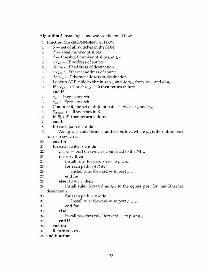
Algorithm 3 Installing a one-way confidential flow
1: function MAKECONFIDENTIALFLOW2: S← set of all switches in the SDN3: d’← total number of slices4: d← threshold number of slices, d′ ≥ d5: srcIP ← IP address of source6: destIP ← IP address of destination7: srcEth ← Ethernet address of source8: destEth ← Ethernet address of destination9: Lookup ARP table to obtain srcEth and destEth from srcIP and destIP.
10: if srcEth 7→ ∅ or destEth 7→ ∅ then return failure.11: end if12: sin ← Ingress switch13: sout ← Egress switch14: Compute R, the set of disjoint paths between sin and sout.15: S dis joint ← all switches in R16: if |R| < d′ then return failure.17: end if18: for each path ri ∈ R do19: Assign an available meta-address mi to ri, where ps,i is the output port
for ri on switch s.20: end for21: for each switch s ∈ R do22: ps,NPU ← port on switch s connected to the NPU.23: if s ≡ sin then24: Install rule: forward srcEth to ps,NPU .25: for each path ri ∈ R do26: Install rule: forward mi to port ps,i.27: end for28: else if s ≡ sout then29: Install rule: forward destEth to the egress port for this Ethernet
destination.30: for each path pi ∈ R do31: Install rule: forward mi to port ps,NPU .32: end for33: else34: Install passthru rule: forward mi to port ps,i.35: end if36: end for37: Return success.38: end function
76

Algorithm 4 Installing a one-way anonymous flow
1: function MAKEANONYMOUSFLOW2: S← set of all switches in the SDN3: d’← total number of slices4: d← threshold number of slices, d′ ≥ d5: srcIP ← IP address of source6: destIP ← IP address of destination7: sin ← Ingress switch8: sout ← Egress switch9: n← no. of anonymizing switches to use, n ≥ 3
10: Construct a list L, where L0 ≡ sin and sout ∈ L. The remaining n − 2 itemsare randomly selected switches from S arranged in a random order.
11: for each switch si ∈ L, si . sin do12: Run MakeConfidentialFlow to provision a confidential flow between
sin and si.13: Inform si of its successor switch si+1 through a confidential message
from sin.14: If si is the intended destination, send si a flag through a confidential
message from sout.15: Run MakeConfidentialFlow to provision a confidential flow between
s and its successor si+1.16: end for17: end function
77

4.7 Adapting the communications model for EtherSlice
In order to retrofit Ethernet for the purposes of transparently providing confi-
dentiality and anonymity to existing network clients, a number of significant
changes have to be made, particularly with respect to the ARP discovery pro-
cess.
The usual first step in establishing IP communications between two hosts on
Ethernet is the broadcast of an ARP discovery message. Given a recipient’s IP
address, the sender attempts to discover the Ethernet address of the recipient
through an ARP broadcast. However, in a privacy-preserving setup, this step is
problematic because it reveals the identity of the destination endpoint. Keeping
in line with our promise not to require changes in the hardware or software of
network clients, the challenge here is to satisfy ARP requests without revealing
any information.
We make two adaptations in our SDN to accomplish this: a controller-
maintained ARP table, and controller-mediated ARP/DHCP replies.
4.7.1 Controller ARP learning
The first change we make is to copy all DHCP and flow-miss messages to the
controller. The goal here is for the controller to become aware of the global
mappings between Ethernet and IP addresses at the earliest opportunity. These
rules are easy to install: at each switch, DHCP-related traffic can be matched
by two independent rules that watch UDP ports 67 and 68, while flow-miss
78

messages can be trapped by a single catch-all wildcard rule installed with the
lowest priority.
In either case, packets that are forwarded to the controller are inspected for
their Ethernet/IP mappings. Acting on this information, the controller main-
tains an authoritative, up-to-date ARP table for these mappings.
4.7.2 Controller-mediated ARP replies
The second required change modifies the behavior of ARP over Ethernet. Under
normal operation, the ARP discovery message is an Ethernet broadcast packet
(ie. Ethernet destination address FF:FF:FF:FF:FF:FF) containing the IP address
whose corresponding Ethernet address a host wishes to look up. This broadcast
packet is propagated to every switch and host over the network. However in
the EtherSlice system, we suppress the propagation of ARP packets by installing
a rule on every switch that redirects all ARP-related traffic to the controller. This
is easy because ARP messages have the exclusive EtherType of 0x0806.
The controller intercepts ARP queries at their ingress switches and replies di-
rectly to them by consulting its authoritative internal ARP table. If no mapping
exists, the controller does not reply but for safety reasons, it also does not flood
the network with the ARP query like a normal network would. Because the
controller replies to ARP queries directly at their ingress switches, ARP probes
can be satisfied without propagating them over the network. Thus, under our
threat model, the attacker cannot learn any information about the intended des-
79

tination.2 As a side benefit, this approach also reduces the broadcast load on the
network since a substantial portion of broadcast traffic is due to ARP [44].
4.8 Resistance to Attacks
In this section, we detail the resistance of our EtherSlice system to certain attacks
that may compromise the confidentiality or anonymity of protected flows on the
network.
4.8.1 Ethernet spoofing
A malicious entity operating on the network may attempt to exfiltrate informa-
tion slices that it is not entitled to by spoofing a target Ethernet address. For
example, if Alice and Bob have established a confidential flow, a malicious en-
tity may try to steal information slices by spoofing either Alice or Bob’s Ethernet
address.
Ethernet address spoofing can be detected from the EtherSlice SDN con-
troller through the installation of appropriate L2 rules. These rules must include
the Ethernet source, Ethernet destination and source port. Spoofing can be de-
tected because a flow miss event will be raised when a (address, port) tuple is
not matched on a switch.2The controller-mediated ARP system does not work for completely passive hosts that by-
pass the DHCP system with statically-assigned IP addresses. The controller would be unableto learn ARP mappings without any traffic from these hosts. However, this is usually not aproblem because most hosts emit some traffic periodically.
80

4.8.2 Sybil attacks
Our EtherSlice implementation is resistant to Sybil attacks because the
anonymity of communications is provided by the switches, which are part of
the trusted network infrastructure, and not by the network users themselves.
Thus, while an attacker may try to overwhelm the network through a denial-
of-service attack by creating many false Ethernet identities, he cannot coerce
switches to deliver him slice data from other network users.
4.8.3 TCAM attacks
Malicious entities that try to cause TCAM overflow attacks can be quickly iden-
tified by observing a disproportionate number of Ethernet source addresses
coming from a port. This port can be shutdown to prevent more traffic from
it. Also, the L2 rules installed for the verified users should never be flushed to
make room for new Ethernet addresses.
4.8.4 Rogue DHCP agents
One weakness with our approach of passively snooping on DHCP traffic is that
it does not prevent the effects of a rogue DHCP server or client. A malicious
DHCP server can compromise information security or cause denial-of-service
on the data network. For example, it could award a DHCP lease with a DNS
and/or gateway pointed at itself, which would allow the rogue DHCP server
to intercept traffic and operate as a man-in-the-middle. It could also cause IP
81

address conflicts by offering an IP address more than once, or by offering an IP
address that is invalid for routing within the network.
Rogue DHCP clients can also cause denial-of-service attacks by exhausting
all available IP addresses from the DHCP server. This prevents other users from
acquiring an IP address for use on the local network.
It is possible to mitigate the effects of both scenarios by relaxing some as-
sumptions about the system. If we permitted the SDN controller to recognize
certain systems as safe and trusted, we can authorize them to handle DHCP
requests. Another possible method is to integrate the DHCP server functional-
ity directly into the SDN controller. To prevent DHCP exhaustion attacks from
clients, we can designate non-switches as endpoints and limit the number of
unique DHCP requests that can be issued per such endpoint.
4.8.5 ARP poisoning attacks
ARP poisoning attacks occurs on a network when a client advertises false infor-
mation about its IP to Ethernet address mapping, and convinces other clients
to use the incorrect mapping. ARP poisoning can be used to facilitate man-in-
the-middle attacks. The EtherSlice system guards against this by prohibiting
client ARP broadcasts or replies from propagating within the network, using an
OpenFlow rule designed to suppress the propagation of client ARP traffic. ARP
queries are performed by SDN controllers on behalf of network clients, and if
an SDN controller observes an ARP advertisement or reply that conflicts with
its internal ARP tables, the SDN controller ignores the ARP message. Thus, a
82

Figure 4.1: Sample workflow in our Mininet setup. Arrows indicate the movement of protected flows.
malicious client cannot use ARP poisoning to convince the SDN controller to
route data slices to it, rendering this man-in-the-middle attack impossible.
4.9 Evaluation
To evaluate our system, we simulated various network topologies using Mininet
[19]. In order to redirect and process data flows, we wrote a custom lightweight
OpenFlow controller. Ordinary data movement across the simulated network
was handled by installing regular L2 flows in Mininet, whereas flows that re-
quired confidentiality or anonymity were redirected to the controller using the
PACKET IN mechanism, effectively using the controller itself as the NPU for
slicing/reassembly operations. Packets that require information slicing opera-
tions were decapsulated from their OpenFlow headers and processed directly
in software using Armadillo [1], a C++ matrix library. Resultant packets were
then re-encapsulated and forwarded back to the simulated switch for output.
In this way, we were able to completely simulate the NPU packet processor in
software. Figure 4.1 shows such a sample workflow.
We tested our system on a variety of network topologies, with varying pa-
rameters of disjoint paths and redundancies.
83
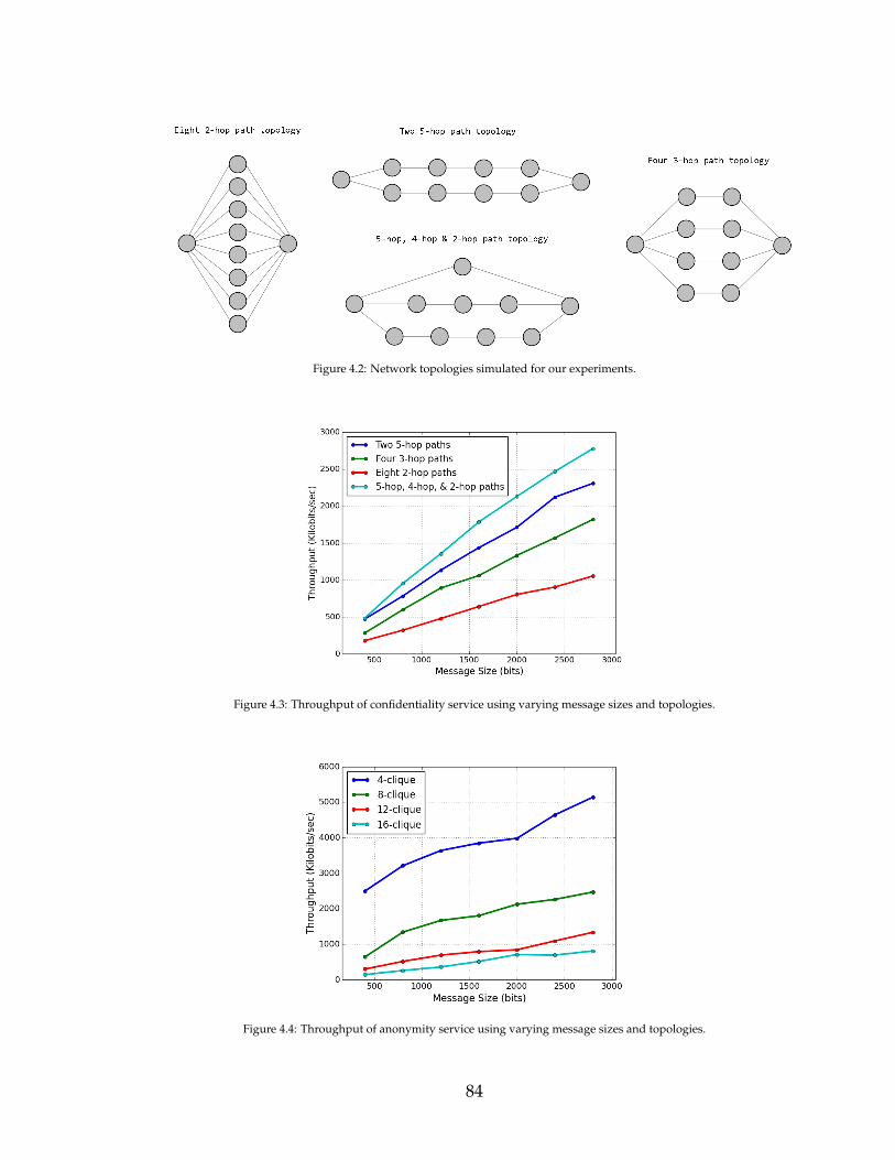
Figure 4.2: Network topologies simulated for our experiments.
Figure 4.3: Throughput of confidentiality service using varying message sizes and topologies.
Figure 4.4: Throughput of anonymity service using varying message sizes and topologies.
84

Figure 4.5: Forwarding graph establishment time for anonymity service with varying number of switches and paths ingraph. Since graph establishment occurs only once to send many subsequent anonymous messages, millisecond setuptimes are acceptable.
Figure 4.6: Throughput of confidentiality service in different simulated networks when varying the redundancy-to-confidentiality tradeoff (varying d’ wrt d). The fraction of slices required for reconstruction is equivalent to the numberof information slices that must be received (or intercepted) in order to reconstruct the original message, divided by thetotal number of information slices sent by the NPU.
85

To measure end-to-end bandwidth, we used iperf, a TCP/UDP bandwidth
measurement tool. Latency was measured using the ping utility.
4.10 Avenues for Improvement
In this section, we discuss some possible modifications to improve the perfor-
mance or functionality set of the EtherSlice system.
4.10.1 Extension to gateways and DNS
While the EtherSlice system covers communications confidentiality and
anonymity within the same Ethernet network, it is possible that users may want
to communicate with external network hosts, while preserving confidentiality
and anonymity as their data flows through the local Ethernet. This naturally
involves the network gateway as an endpoint, and is problematic because an
anonymizing set that contains the gateway is very likely to involve communica-
tions that exit the network. On a related note, clients that wish to communicate
with endpoints outside the network may also consult the local DNS in order to
resolve IP addresses. This DNS lookup step can be a dead giveaway that reveals
the penultimate destination of a user’s data flow.
A simple way to preserve anonymity in situations that require gateways and
DNS is to force all anonymizing sets to include the network gateway(s) and
DNS. This increases the computational and traffic load on these systems, but
can be mitigated by provisioning multiple network gateways and DNS.
86

4.10.2 NPU improvements
Our prototype implementation of the NPU is software-based and depends on
the PACKET IN mechanism in Openvswitch. This method does not provide
high packet throughput on real switch hardware. An ideal NPU should be a
dedicated system, ASIC hardware or FPGA (such as the NetFPGA) that can
process data packets at line rate.
4.11 Conclusion
We presented the design of a practical system to retrofit confidentiality and
anonymity to an Ethernet-based network. Our system is completely backward-
compatible with existing hardware and software, necessitating no changes with
network clients or their operating systems. Finally, the evaluation shows that
our prototype is realistic and has reasonable performance.
87
CHAPTER 5
A CONTROLLER BUILT FROM OPERATIONAL EXPERIENCE
In this section, we chronicle our experience with practical OpenFlow controller
design. The design is based on OpenFlow 1.0, although OpenFlow 1.3 is avail-
able on the Dell hardware. The reason we selected to use OpenFlow 1.0 instead
of 1.3 is because the hardware only supported 1.0 for a long time, and 1.3 did
not offer significant new features on the hardware we used. Furthermore, the
1.3 protocol was far more complex.
Interest in OpenFlow and software-defined networks (SDNs) has resulted in
a boom in SDN hardware and controller offerings, with varying degrees of ma-
turity, popularity and support. However, few studies have been conducted to
investigate the interaction between SDN hardware and software, as well as its
impact on controller design and implementation. In this chapter, we chronicle
our experience with deploying two commodity SDN controllers and a new sys-
tem, Ironstack, of our own design in a production enterprise network at Cornell
University, and describe the lessons learnt. We also report on several practi-
cal limitations of SDN and controller technology, and detail important future
challenges for SDN adopters and developers.
5.1 Introduction
The success and excitement surrounding SDNs belies the fact that actual
hardware support for OpenFlow spans a wide spectrum. Older OpenFlow-
compliant devices often lack the necessary firmware to support some of the
88

more recent versions of OpenFlow. Even among hardware that support
the same version of OpenFlow, varying manufacturers, implementations and
cost/performance tradeoffs result in different coverage of OpenFlow com-
mands. Furthermore, the OpenFlow specification does not mandate the sup-
port of optional commands listed in the standard. Furthermore, some vendors
provide non-standard OpenFlow adaptations or extensions [6].
Another issue is that many enterprises do not actually write their own SDN
controller software, and view OpenFlow more as a unifying standard than as
an opportunity to innovate by creating new specialized control paradigms. Our
own research on a new SDN controller we call Ironstack focuses on automat-
ing fault-tolerance and security for deployments into challenging settings [82].
But in dialog with potential users we often find that the system owner is less
focused on features than on convenience and the level of effort needed to actu-
ally deploy and manage the solution. Given an easily deployed, easily operated
technology, feature coverage and special properties emerge as a secondary goal.
Yet in settings like Cornell, where our networks are managed by an in-house
professional team, the fear that SDN might be overwhelmingly complex and
suitable only for research and experimentation actually dominates the appeal
of standardization. Thus until SDN learns to be a user-friendly turn-key story
for the SDN manager, it is unclear how the full potential of the technology could
be leveraged.
This chapter first presents our experience in building and operating a small-
scale production OpenFlow SDN from scratch, using market-available hard-
ware and off-the-shelf general-purpose OpenFlow controllers. We also discuss
limitations of existing commercial options. We then describe the impact of
89

lessons learned and turn these into recommendations. Finally, we discuss some
practical challenges that lay ahead for programmable network technology.
5.2 Overview of the Gates Hall SDN
Cornell’s Gates Hall SDN comprises 15 high-capacity Dell S4810/S4820 10Gbps
switches linking approximately 300 physical hosts over 3 machine rooms and
multiple instructional and research labs, providing service to over 1000 students
and faculty.
Administratively, the SDN is solely managed by the Information Technol-
ogy Support Group (ITSG), a team that oversees and supports all engineering
IT needs. ITSG does not engage in research, nor in SDN programming as an ac-
tivity: their role is to ensure that the network operates in a correct, secure, and
administratively controlled manner. However, uplink to the general campus
network is provided and managed by a different campus-wide organization:
Cornell Information Technologies (CIT). CIT requires an L3 isolation router that
separates the SDN from the rest of the campus. The L3 isolation router is seen as
an emergency kill switch in the event that the SDN interferes with the general
campus network. This router is the sole connection to the campus network (by
feeding into one of the three main campus routers), and is also responsible for
assigning and managing IP addresses for all hosts on the Gates Hall SDN.
Physically, all machines on the SDN share the same switching infrastruc-
ture. In order to support Cornell’s diverse mix of networking research, the SDN
is fragmented into VLANs. Each VLAN is a continuous L2 segment configured
with access permissions specific to the usage patterns of its member machines,
90

so membership in a VLAN provides a coarse form of access control. For exam-
ple, several racks within our datacenter supporting operating systems research
require PXE boot and an internal DHCP server within their cluster, yet the clus-
ter itself is not permitted to communicate with the external world. These ma-
chines are assigned to a VLAN distinct from the one used to service instructional
lab machines which must be accessible remotely over the Internet. Although the
principle of VLAN isolation could be considered archaic on an SDN compared
to appropriately provisioned rules, it nonetheless provides a convenient point
of control at the L3 isolation router, where all SDN VLANs converge.
Figure 5.1: Topology of the Gates Hall SDN.
91

5.3 Hardware slicing
The SDN switches in Gates Hall are a combination of high-capacity Dell S4810
and S4820 switches. These switches are identical except for the physical ports
exposed on the front panel: the S4810 switches feature copper SFP (small form-
factor pluggable) ports while the S4820 use regular 8P8C (8 position 8 contact)
ports. The 8P8C ports are physically more compatible with a wider range of
devices, making it substantially easier to connect to commodity Ethernet de-
vices. Both models of switches are capable of being ‘sliced’1 into instances,
thereby allowing multiple controllers to operate on logically disjoint portions
of the hardware. This is conceptually similar to the virtualization provided by
FlowVisor [80], except that the hardware enforces the isolation. Two methods
are available for this slicing.
5.3.1 Port-based instances
In port-based slicing, a Dell S4810/20 switch may be arbitrarily partitioned into
as many as 8 concurrent instances of disjoint ports. Not all ports have to be
assigned to an instance. Each instance can be associated with an independent
OpenFlow controller, essentially partitioning the switch physically into multiple
smaller switches. Using port-based partitioning, network topologies of up to 8
switches can be simulated using a single piece of hardware. This feature has
proven useful in many experiments that we have conducted.
1The term ‘slice’ first appeared in GENI [43] literature and was used in FlowVisor [80] todescribe a similar concept.
92

Port-based isolation has the advantage that it is easy to set up and intuitive
from the physical and OpenFlow controller standpoint. We recommend using
port-based instancing for developers or researchers beginning in the field.
5.3.2 VLAN-based instances
An S4810/20 switch configured to operate with VLANs in OpenFlow mode can
also slice the hardware into instances through VLAN assignments. When op-
erating under this mode, physical ports on the switch are assigned VLAN IDs
and marked as tagged or untagged. The tagging status indicates whether a
port emits and accepts IEEE 802.1Q frames [83], or regular untagged Ethernet
frames. Ports with more than one VLAN ID assignment cannot be marked as
untagged.
Up to 8 controller instances may be provisioned this way. Each OpenFlow
controller is assigned to manage a set of VLAN IDs, which must be disjoint
from other sets of VLAN IDs managed by other controllers. From the Open-
Flow controller point of view, the viewable set of physical ports comprise those
that are assigned to the VLAN IDs under the instance’s control. In addition,
ingress traffic on VLAN-tagged physical ports are filtered to retain only packets
relevant for the set of VLANs managed by that instance, so a controller for a par-
ticular instance will only see tagged VLAN traffic corresponding to its assigned
set of VLAN IDs. Other VLAN traffic arriving at the switch is either sent to
another relevant managing instance or dropped. The S4810/20 hardware auto-
matically enforces VLAN isolation on a hardware level, and no OpenFlow rules
are necessary for this enforcement.
93

VLAN-based isolation is useful in an environment with multiple VLANs
and non-OpenFlow switches, when flow rules need to be conserved and/or
some hardware oversight is desired to prevent controllers from making mis-
takes enforcing VLAN isolation. However, this mode of operation is techni-
cally non-compliant with the OpenFlow standard and has behavior that can be
confusing for people new to OpenFlow. For example, an administrator wish-
ing to create a layer 2 rule that forwards flows from a tagged to an untagged
port should specify a match criteria with an Ethernet destination address and a
VLAN ID. However, the action set cannot include a directive to strip the VLAN
tag (an OFPT BAD ACTION error would be returned by the switch), even if it
seems logical to do so before outputting the packet to an untagged physical
port. Instead, the switch performs tagging and untagging automatically. Other
operations in VLAN-based isolation mode, such as a flow rule that copies all
packets from one physical port to another, may simply not work without any
warning or error.
5.4 Experience with controllers
Our operational experience2 with OpenFlow SDNs spans about 24 months, of
which 4-6 months were spent on hardware familiarization and micro experi-
ments involving isolated switches. With the SDN fully deployed in February
2014, we sliced every switch into 4 VLAN-based instances and ran different
controllers on each instance. The first two instances ran production traffic using
an open source controller (”Controller A”) and a commercial controller (”Con-
2The authors are not affiliated with Dell, the Linux Foundation, or any organization forwhose products are mentioned or featured in this chapter. The views expressed herein aresubjective and not indicative of any product endorsement or criticism.
94

troller B”) respectively, while the latter two were reserved for research and de-
velopment purposes and ran our Ironstack controller for the full period of the
study. Our switch firmware only supported OpenFlow 1.0 at the time the net-
work went into production (1.3 support arrived in spring 2015) so most of our
anecdotal experience is based on the older standard. However, we believe that
our insights transcend versions and remain relevant.
5.4.1 Controller A
Controller A is an open source OpenFlow controller that has enjoyed
widespread popularity since its initial release a few years ago. The system is
designed to operate in a centralized manner, with all OpenFlow switches di-
rectly connected to the controller. Because of this centralized mode of opera-
tion, the controller maintains an up-to-date view of the SDN topology, as well
as all ancillary switch data (such as flows, port statuses and traffic counts). The
web interface offered by the controller allows convenient administration of the
network through an intuitive webpage accessed from the control network.
We first encountered trouble on the SDN when we grew our network to ap-
proximately 200 hosts. At that scale, we started to experience intermittent per-
formance issues caused by discontinuous hardware flow rules on some source-
destination paths. These problems would manifest as high-latency (approxi-
mately 500-1000ms), lossy flows alongside other flows that perform well. We
determined that packets transiting these discontinuities caused flow-missed
events to be raised in OpenFlow, which caused these packets to be encapsu-
lated and forwarded to the controller for processing. To ensure delivery, the
95

controller used software forwarding to copy the packets to their destinations.
Our investigations also revealed no capacity problems with the switch hard-
ware table, and we concluded that the rules were simply not being installed
by the controller despite continuous flow-miss events resulting from the flow
discontinuities. We were able to rectify the problem by manually installing the
missing rules on the affected switches.
To find out if the missing flow problem was correlated, we restarted the con-
troller multiple times. We found that controller restarts frequently rectify the
problem of missing flows in some source-destination paths, but it did not pre-
vent the same problem from recurring on other paths. Furthermore, the con-
troller removes all hardware flows during a software restart, causing a long
period of degraded network operation as the controller repopulates its view of
the SDN and falls back on software forwarding in the interim. On our 15 switch
network, it takes about 10-15 minutes for this controller to recover after a restart.
5.4.2 Controller B
Controller B is a commercially available, proprietary 1U integrated server/Open-
Flow controller. It is marketed as a turnkey solution that is simple to use and
fast, and the system has received many accolades over the years since it was
first available several years ago. The controller is also centralized and provides
multiple ways for an administrator to view and manage the network, such as
through the command line and over the web. The system is robust and is able
to maintain a running view of the operational data and SDN topology.
96

This controller also experienced scaling issues on our SDN at approximately
200 hosts. Although the controller did not create discontinuous paths, it would
sometimes refuse to setup flows for a newly-introduced system. Consequently,
the system does not appear on the topological view and does not receive net-
work access. We have also encountered connectivity issues following rapid cy-
cling of a network device’s link state: the controller enforces a lockdown period
of about 15 minutes before returning the device to active use.
5.4.3 Ironstack
Length limitations prevent a detailed discussion of our Ironstack controller. In
brief summary, Ironstack is an open source SDN controller intended to offer a
turn-key operator experience while imposing a flexible set of security and reli-
ability guarantees at the fabric level, for example by multiplexing traffic across
redundant SDN links and encrypted for protection against intrusion. For our
purposes here, the details are not important, because as it turned out, the op-
erator experiences of the ITSG and CIT teams had a far greater role in shaping
technology deployment choices than the special features Ironstack was actually
created to showcase.
Because ITSG and CIT were unable to successfully deploy controllers A and
B in stable configurations, for a period of time ITSG actually only used Iron-
stack in the full SDN system. Eventually, as campus network security policies
evolved, a decision was made to run Ironstack only within our research slices.
Thus we have a total of 24 months of experience with Ironstack, of which 10
months included our full production network. When Ironstack was cut back to
97

research-only use, the entire production workload was shifted to the standard
(switched Ethernet) CIT network and off of SDN, highlighting the continuing
concerns about SDN stability and manageability in production networking en-
vironments.
5.5 Lessons learnt
5.5.1 The switch-to-controller pipe is thin
One of the first lessons we verified is that the OpenFlow control connection
between the switch and the controller is a serious bottleneck. This corroborates
with findings from other prior work [80] [40]. On our Dell S4810/20 hardware
with TLS turned off, the control connection rarely exceeded a throughput of
2.54Mbps on a dedicated 1Gbps out-of-band network port. This is a few orders
of magnitude lower than the maximum speed of the network port, and could
not be explained by slow link activity. We found that the bottleneck was due
to an overloaded switch processor. The embedded processor runs the Force10
Operating System, a variant of Linux that provides OpenFlow agent support
through an application layer.
Because the switch processor is heavily taxed by other scheduling demands,
OpenFlow functionality is prone to slowdowns at high loads. This effect is es-
pecially pronounced during times of high PACKET IN throughput. PACKET IN
events are most commonly generated in response to flow-misses, where a
switch forwards a packet to the controller following a failure to find a matching
OpenFlow rule. Even on switches with light network traffic, consecutive flow-
98

miss events can quickly overwhelm the CPU, leading to dropped PACKET IN
messages, slow OpenFlow throughput and high latencies processing OpenFlow
commands on the switch.
PACKET IN events may also be generated in response to an explicit request
for flow traffic to be forwarded or copied to the controller. This is helpful in
certain circumstances when a controller wishes to discover network state (for
example, by snooping on all ARP and DHCP packets). However, flow-miss
events will experience contention and be negatively impacted by PACKET INs
received through this method. To minimize flow-miss packet losses, we advise
against explicit copying of flow packets to the controller where possible.
5.5.2 Consider not flushing rules on restart
Many OpenFlow switches today have a fail-secure mode that allows installed
flows to remain on a switch and provide limited operational continuity should
the controller be disconnected. Our experience with controllers A and B shows
that a complete rule removal on controller restarts is often unnecessary, and
can be counterproductive in some situations. Apart from occasional flow dis-
continuities, the controllers typically regenerate the same rules across restarts.
However, manually-inserted rules (such as those used to circumvent flow dis-
continuities) are lost when all flow rules are cleared.
Because complete rule regeneration from a scratch is a time-consuming op-
eration and SDN controllers are unlikely to be adversarial (by installing bogus,
broken, or harmful flow rules for its successor), we recommend against the prac-
tice of flushing all flow rules during a controller restart unless there is reason to
99

suspect that correctness may be compromised on a large scale. Rules installed
by a predecessor represent the product of some computation or planning and
should not be wasted. Instead, we suggest that rules be inherited and veri-
fied for preservation on controller startup, and an alternate strategy be used for
clearing the flows on the switch if needed.
Clearing the flow table instantly and in its entirety is rarely needed as an
emergency procedure. If a genuine need to remove flows arises, we suggest that
they be removed one at a time or in small quantities batchwise. On OpenFlow
1.0, the controller can do this by first initiating an OFPT STATS REQUEST with
a request of OFPST FLOW to retrieve a list of all flows on the switch, and then
issuing staggered OFPT FLOW MOD requests to remove flows one at a time. The
overall effect is to spread out flow deletes that would immediately cause flow-
miss events: should the controller remove a flow that was actually active at the
time, the resulting flow-miss packets would be less numerous than if multiple
flows were generating flow-miss events in response to a bulk removal request.
In turn, the switch is less likely to drop flow-miss events, and the controller can
establish new flows more expediently.
On the other hand, if the intention of the controller is to prune unneeded
rules without disrupting any flow, it could do so in an unintrusive manner. The
controller could identify passive flows by sampling the list of all individual flow
statistics retrieved from the switch via the OFPT FLOW STATS request. Flows
that have not seen new packets in a certain amount of time can be deemed to be
inactive and individually removed to free up entries in the flow table.
100

5.5.3 Be cognizant of hardware limitations
Although the OpenFlow specification provides a comprehensive array of
matching criteria and actions that can be combined in many useful ways, the
reality is that these OpenFlow capabilities are limited to what the hardware ven-
dor chooses to support. The OpenFlow switch specification describes the full set
of actions that a switch may implement, however switch vendors are only ob-
ligated to support actions that are marked as ‘required’. In the 1.0 version of
the specification, mandatory action support only extends to dropping packets
or forwarding to certain ports; useful actions such as packet header field modi-
fication and port flooding are optional and may not be available.
Furthermore, even similar actions across different hardware could have var-
ious performance characteristics [79] [52]. This non-uniformity of OpenFlow ac-
tion support and performance can be a source of surprise and frustration to the
OpenFlow developer, who may build generic software controllers and support
equipment that become functionally degraded or even completely incompatible
with real-world hardware. On the other hand, a developer that targets specific
hardware may be exposed to vendor lock-in as it is unlikely that all other Open-
Flow hardware will provide a similar level of support, let alone behave iden-
tically. This point was an especially acute lesson for us because we had been
developing early versions of our OpenFlow controller using Open vSwitch [22]
as a reference switch. As a result, we committed substantial time to implement-
ing features that worked well under Open vSwitch but were not well-supported
in hardware. For example, at the time of our early prototype, our Dell S4810/20
switch did not support the OpenFlow action to strip VLAN tags and we had to
101

emulate this functionality in software, severely degrading the performance of
our system.
5.5.4 Equipment-specific features can make a big difference
We attempted to understand the reasons for the scale limits experienced by the
controllers we used. The Dell S4810/20 hardware feature multiple forward-
ing tables. On these switches, flows can be differentiated by types to fall into
one of the ACL, L2 or L3 flow classifications. Ordinarily, the multiple forward-
ing table functionality is disabled and all flows are stored in the ACL (general-
purpose) OpenFlow table, which has capacity for only 500 flows. When enabled
through an out-of-band command line configuration utility, the switch transpar-
ently stores flows matching L2 or L3 classifications into dedicated separate ta-
bles. The L2 and L3 flows are particularly compelling because they feature deep
tables well-suited for common switching and routing tasks, freeing up valuable
ACL table space for more unusual flow rules. Table 1 shows the respective flow
table capacities on the S4810/20 switches, while Tables 2 and 3 show the respec-
tive syntaxes of the L2 and L3 flows [6].
Table name Flow capacityACL 500L2 48000L3 6000
Table 5.1: Flow table capacities on Dell S4810/20 switches.
Our investigation showed that both Controller A and Controller B installed
rules that did not fit into either of the L2 or L3 flow classifications. Instead,
those flow rules were placed into the ACL table, which prevented the network
102

Parameter type ParametersMatch criteria • dl vlan (input VLAN ID).
• dl dst (destination Ethernet address).• all other fields must be wildcarded.
Actions • OFPAT OUTPUT output to a single phys-ical switch port.
Table 5.2: L2 flow classification.
Parameter type ParametersMatch criteria • dl dst must be set to the switch port’s
Ethernet address.• dl type must be set to 0x0800.• nw dst can be optionally set.• all other fields must be wildcarded.
Actions • set dl src must be set to switch port’sEthernet address.• set dl dst (destination Ethernet ad-dress).• OFPAT OUTPUT output to a single phys-ical switch port.
Table 5.3: L3 flow classification.
from scaling once the table was full and no new flows could be created. We dis-
covered that the reason for using ACL entries was because the controllers were
unaware of the syntax or availability of the L2 and L3 tables, which prevented
them from taking advantage of the deep tables. In contrast, Ironstack did not
make substantial use of ACL entries at all because the policies ITSG sought to
support were mostly simple enough to be expressed in L2 flows.
5.5.5 Non-standard behavior is standard
Specification-deviating behavior may come as a surprise for developers who as-
sume that hardware marketed as OpenFlow-compliant will exhibit features and
103

functionality exactly as written in the OpenFlow standard. This can be an issue
for developers who build their controllers on reference switch implementations
(eg. Open vSwitch) and later deploy them on actual OpenFlow hardware.
Non-standard hardware behavior has caught us by surprise on a number of
occasions. On our Dell S4810/20 switches, flow priority is only honored within
entries in the ACL table; the priority field is completely ignored for flows that
fit in the L2 or L3 tables. This posed a problem for our controller, as it had to
be aware of these equipment subtleties and install flows into the ACL table if it
wished to override specified flows in the L2 or L3 tables.
As another example on our hardware, L2 flows are not instrumented with
packet or traffic counters, which limits their utility in network analysis. This
forces the developer into a dilemma between the creation of an instrumented
ACL flow on a capacity-limited table, or an uninstrumented L2 flow on a large
table. To complicate the situation, L2 flows cannot be configured with arbitrary
idle timeouts; these flows are either permanent (if the idle timeout value is spec-
ified as 0 in the flow rule), or set to some switch preset value (if the specified idle
timeout value was non-zero). Since there are no indications of warnings or er-
rors when L2 flows are installed with arbitrary timeouts, an equipment-agnostic
controller may mistakenly assume the flow to time itself out accordingly.
On the L3 table, flows are permanent and do not honor any specified idle
timeouts. Similar to L2 flows, no information is given by the hardware to indi-
cate that the idle timeout is ignored on an L3 flow.
While these non-standard behavior are generally innocuous quirks, they
make it difficult for a developer to write a general-purpose OpenFlow con-
104
troller that exhibits predictable behavior across different hardware. For exam-
ple, an OpenFlow controller used to drive a commercial pay-per-use network
might rely on L3 flow timeouts to redirect a customer to a captive portal when
a lease time expires. Without equipment-specific knowledge of non-standard
flow timeout behavior, general-purpose controllers may not correctly enforce
customer access policies. In the case of an L2 flow, a software workaround for
the idle timeout may not even be possible since it offers no packet counters that
can be used to track flow activity.
5.5.6 Configuration tools are just as important as OpenFlow
Although OpenFlow presents a useful interface through which a switch may
be controlled, the specifications omit a discussion of equipment configuration
tools or utilities because they are often vendor and equipment-specific. Equip-
ment configuration tools provide the means to set up operating parameters that
are not necessarily controllable from or related to OpenFlow. For example, the
IP address and port number of a controller must be specified to the switch be-
fore it can establish an OpenFlow connection to the controller. Other important
functionality that are only accessible through equipment configuration tools
may include means to power cycle the device, set up VLANs and port tags,
as well as enable specific OpenFlow tables or slicing features. On most Open-
Flow switches that we are aware of, the configuration tool presents itself as a
command line interface physically accessed through the switch’s serial (RS232)
port. Because OpenFlow switches have their own IP addresses on the control
network, they often also support access to the same configuration tool over tel-
net or SSH.
105

We take the view that control over these functionalities is just as important as
OpenFlow itself in a comprehensive network controller, particularly if the con-
figuration utilities also provide information or indirect control over OpenFlow
capability on a switch. As an example relevant to our SDN setup, a network
controller should be able to inspect the switch configuration for VLAN or port
information pertaining to its slice. It should also be able to control deep table
options or reconfigure the IP address and port that the switch seeks a controller
at. We are presently unaware of controllers that can perform equipment config-
uration along with OpenFlow.
5.5.7 Switch misconfiguration can cause confusion
Even with compatible controllers designed to correctly take advantage of the
various hardware tables available, it may still not be apparent to the controller
that the hardware tables are indeed being used. On the Dell OpenFlow switches,
an external configuration utility must be used to manually enable the switch to
operate in ’multiple-flow’ table mode, and then the individual L2 and L3 flow
maps have to be enabled in order for flows specified in the L2/L3 formats to be
stored into their high capacity hardware tables. Without the features enabled
(which is the default), these flows would be stored in the ACL table.
On our SDN setup, there is no way for a controller to verify that the flows
have been stored into the right hardware table, since OpenFlow flow statistics
from our Dell hardware do not annotate flows with their flow table IDs. Fur-
thermore, the OpenFlow specification does not provide a way to obtain table
capacities, which precludes the ability for a controller to make an informed de-
106

cision with respect to flow installation. The only way that a controller can tell if
a table is full is when the error OFPMFCTABLEFULL is generated in response to
a flow installation command. By this time, it may be too late for the controller
to take remedial action. On the other hand, such table capacities are usually
advertised by the vendor or otherwise accessible from the switch configuration
utility. We believe that knowledge of table capacities should be propagated to
the controller to aid planning purposes.
5.5.8 Isolation is not perfect
Virtualization on an OpenFlow switch provides logical isolation between one
controller’s traffic from another. Virtualization techniques can be software-
based, as in FlowVisor [80], or hardware-based, as is provided directly on the
Dell S4810/20 switches. In either case, it is important to note that virtualization
does not provide perfect resource isolation between controllers. Resources such
as the embedded CPU, forwarding table capacity and bandwidth are shared
across all controllers working on the switch.
This is a well-known phenomenon with all virtualization techniques, and is
neither a flaw nor bug in the virtualization mechanism. However, controllers
should be designed with the assumption that they could be run on virtualized
hardware, and thus engage in better cooperative sharing tactics. For example,
controllers could minimize flow table wastage by setting an idle timeout on
their flows, while also not consuming excessive switch computational power
by indiscriminately copying data plane packets to the controller.
107

5.5.9 No controller-to-data plane communications
One feature that we would have liked to see in a SDN controller is the abil-
ity to communicate directly with networking applications that run on the data
plane. At present, we are not aware of any controllers that have such a ca-
pability, except for Google’s B4 [53] Routing Application Proxy, which bridges
packets from the Quagga control plane and the switch’s data plane. The ability
for a network application to communicate directly with the controller opens up
substantial development opportunities. For example, the controller can host a
HTTP subsystem that serves users statistics about their network usage, or pro-
vide a webpage through which network QoS could be requested. A data plane
presence on the network also allows the controller to easily implement features
such as captive portals.
5.6 Building a controller from ground-up
To validate the applicability of the lessons we learnt, we built our own Open-
Flow controller from ground-up, applying the prior experience we gained
working with OpenFlow hardware and controllers. Our design is exploratory
and unusual, but principled and feasible. The following subsections detail the
implementation of our system.
108

5.6.1 Hierarchical design
A key departure from the architecture used in many other controllers is that
our system is hierarchical, rather than centralized and monolithic. In our hi-
erarchical design, every switch is mapped to one low-level controller process.
Each low-level controller has full control over its switch, but limited visibility
of the entire network. One or more high-level controllers operating on the con-
trol network communicate with the individual low-level controller processes
via remote procedure calls (RPCs) and coordinate global activity, such as alter-
nate path provisioning and network analysis. We chose a hierarchical design
for several reasons:
Figure 5.2: Hierarchical controller design. Dotted lines represent network links on the data plane; solid lines are linkson the control network. Note that high-level controllers do not need to be connected to every low-level controller.High-level controllers may also run distributed coordination logic amongst themselves.
109

Faster per-switch tasks
Many OpenFlow tasks do not require a master coordinator or centralized con-
trol in order to function correctly. For example, echo requests, which are issued
asynchronously by the switch and serve little purpose other than to keep an
OpenFlow connection alive, are more expediently processed by the low-level
controller. This relieves the high-level controller from unnecessary processing
and burden, freeing it up for tasks that are better solved at a higher level.
In fact, even tasks such as basic flow provisioning can be typically performed
by low-level controllers, without a need for a complete view of the network. The
low-level controller may simply act as a learning switch and install the appro-
priate flows. The high-level controller may intervene at a later time and instruct
the low-level controller to update the flow rules as necessary.
Simpler program logic
A low-level controller designed to attach to a single switch requires less state,
concurrency and complexity since it does not need to coordinate multiple
switches or perform CPU-intensive global tasks such as determining optimal
flow placement. Correspondingly, low-level controller code is more compact
and easier to debug. Resource usage on the low-level controller is also light and
predictable, with the worst case processing demand caused by heavy OpenFlow
traffic on a single switch.
Similarly, with the high-level controller would be simpler to implement as
it does not require code to perform low-level switch management. Instead, the
110

code could be focused on issues that are best tackled at a global scale, such as
network analysis and flow placement optimization.
Versatile load-balancing
One significant advantage of our hierarchical design lies in the scalability of our
controller. While centralized controllers can be scaled to a limited degree by
running on a server with higher processing power, the approach is somewhat
inflexible and expensive. The hierarchical design allows for considerably more
flexibility in the placement of the individual low and high level controllers. On
one extreme end, each low-level controller could be made to run on separate
physical hardware. This hardware need not be expensive or even computa-
tionally powerful. In our experience, a low-level controller is capable of effi-
cient operation on a $35 single core Raspberry Pi (model B), a low-power, low-
performance computer.
On the other extreme end, all low-level controllers could be made to run as
individual processes on the same physical machine. This is easily configured by
pointing the OpenFlow switches to seek their controllers at different ports on
the same IP address. When load becomes a bottleneck on the physical machine,
the processes may be spread out over more servers, with only a minor switch
reconfiguration required to update the controller IP and/or port.
We anticipate that our approach is more scalable and future-proof: apart
from flexible controller placement, it is also conceivable that future switches
may offer sufficient on-board computational power or co-processors that enable
111
user-level controllers to be run directly on or in close proximity to the switching
hardware.
Resilience to outage
The centralized nature of most OpenFlow controllers is a well-known vulnera-
bility in SDNs [60] [58] [84] [54] [34] [63]. The behavior of an OpenFlow switch
under a controller outage depends on whether the secure fail-mode option is
available and enabled on the switch. The secure fail-mode feature preserves
flows on a switch, allowing some continuity in service, although new flows can-
not be established.
Software faults leading to controller failures are common, although control
network outages can also cause a switch to lose its connection with a controller.
The net effect in both cases are identical: the affected switches go into secure
fail-mode, or purge their flows while awaiting successful reconnection with the
controller.
In the best possible scenario where all switches on an SDN support secure
fail-mode, the impact of a centralized controller outage is the global inability
to establish new flows. This effect may be quite noticeable on a large network,
where many new flows are created frequently. On the other hand, a hierarchical
setup limits the extent of the problem to the switches for which their low-level
controllers have failed or become uncontactable. Other low-level controllers can
continue to create new flows, reducing service disruption on the global scale.
The advantages of a hierarchical design are more pronounced in the worst-
case scenario. If none of the OpenFlow switches in a network utilize secure
112
fail-mode, then all flows are lost on every switch (or on switches that have lost
connection to their controller). A centralized controller would face immense
load on a restart as it restores flows across numerous switches, leading to poor
network performance that can last many minutes. With a hierarchical design,
only switches corresponding to failed low-level controllers are affected, and the
recovery time can be relatively short since each low-level controller restart has
to handle service restoration for just one switch.
Separation of the high-level controller from the low-level controllers also has
the advantage of isolating faults that are not directly related to switch manage-
ment. For example, a flow optimizer unit or third party SDN plugin running
on the high-level controller could become unstable during deployment. Un-
der a hierarchial design, the high-level controller crash would not affect the
basic functionality of the network, which depends on low-level controllers. An
equivalent setup in a centralized controller could result in network outages even
though the unstable code had no direct relation to OpenFlow switch manage-
ment.
Better Performance
Third-party plugins or modules for an OpenFlow controllers is a popular idea
due to the extensibility and customization that these plugins provide. However,
on monolithic controller architectures, these plugins generally run in the same
process and compete for resources that are also used for OpenFlow manage-
ment. By separating the execution of these plugins from switch management,
the high-level controller can perform as much computation as it needs without
being concerned about slowdowns with other switch-specific tasks.
113

5.6.2 Hardware abstraction layers
To abstract away differences between heterogenous hardware, our low-level
controller provides generic interfaces to execute common tasks such as provi-
sioning flows or querying the remaining capacity of specific tables. Although
we have not built a full driver layer for this purpose, the equipment-specific
code to perform these tasks reside in different modules that are selectively ac-
tivated according to the identity of the attached hardware. The hardware iden-
tity can be specified at controller startup time via command line flags, or by
automatic detection during the handshake phase of the OpenFlow connection.
Automatic detection relies on the data returned by the switch in response to an
OFPST DESC stats request, which contains verbose information pertaining to
the manufacturer, hardware/software description and even the serial number
of the switch.
In the case of the Dell S4810/20 switches, the hardware abstraction layer
adapts certain operations to improve their functionality on the hardware. For
example, simple flow provisioning requests for a learning switch are translated
into more space-efficient L2 table rules before being installed on the hardware,
thus keeping the ACL table as lightly loaded as possible. This is in contrast to
the hardware abstraction layer for generic OpenFlow switches, which installs a
rule with different syntax (that same rule would be installed in the ACL table
on the Dell switches).
114

5.6.3 Built-in switch configuration module
Our low-level controller is designed with a built-in module that is capable of in-
terfacing with the configuration utility on its assigned switch. Prior to accepting
an OpenFlow connection from the switch, the low-level controller establishes a
telnet or RS232 connection to the switch and queries it for critical bootstrap in-
formation. On the Dell S4810/20 hardware that we use, the set of information
queried by the configuration utility include the instancing mode (port-based or
VLAN-based), the list of pertinent VLAN IDs, as well as the set of each VLAN’s
tagged and untagged ports. Additionally, the module verifies that the switch
will connect to the correct IP address and port for the low-level controller.
The module maintains an open telnet or RS232 connection with the switch
even after the OpenFlow control connection is made. This provides the low-
level controller access to configuration options and commands that may be in-
voked remotely by a high-level controller. For example, a high-level controller
may reboot the switch remotely by relaying its intention through the low-level
controller. Global flow table resource usage is also monitored this way.
5.6.4 Controller data plane presence
An accessible controller presence on the data plane network can be very useful
for developing novel solutions that require direct point-to-point communica-
tions between data plane applications and the controller. However, in order to
avoid being in a chicken-and-egg situation where an SDN controller controls
its own connectivity to the switch, most OpenFlow switches require that the
controller be present on a logically separate network. This network is known
115

as the control network and is typically dedicated to communications between
switches and their controller(s). The logical separation between the two net-
works present a tricky communications barrier, and we present two solutions to
solve this problem.
Low speed data plane presence
Although the OpenFlow protocol does not directly provide support for point-
to-point communications between an application on the data plane and the
controller, a crude form of communications may be achieved by exploiting the
PACKET IN and PACKET OUT functionality to emulate a host presence on the
data plane.
This approach relies on the observation that a correctly-functioning packet
processing system that appears to send and receive legitimate packets is indis-
tinguishable from any other valid network entity. Thus, if the controller were
to assume a valid Ethernet and IP address, and generate traffic or respond to
network activity on the data plane in a protocol-correct manner, it would come
across as a presence on the data plane.
Achieving basic bidirectional communications is straightforward: to receive
packets from network applications on the data plane, the controller sets up a
rule to forward all packets with the controller’s emulated Ethernet address to
the virtual OFPP CONTROLLER OpenFlow port. Thereafter, packets directed
at the controller’s Ethernet address will be forwarded to the controller via
PACKET IN events, along with their ingress port numbers. To send data, the
controller encapsulates a packet with the PACKET OUT command along with an
116

output port (or ports) directive, and the switch delivers the packet on the data
plane.
However, a bidirectional communications primitive is not sufficient. In or-
der for the controller to operate legitimately on the data plane, it needs a proper
Ethernet and IP address. Although Ethernet addresses could be squatted on
or fabricated with a low probability of collision, it is considered bad form. A
better approach is to use the least significant 48 bits of the datapath ID corre-
sponding to the switch that the controller is acting on. These 48 bits correspond
to the switch’s Ethernet address, which is likely to be unique since hardware
vendors typically issue distinct addresses allocated from their Organizationally
Unique Identifer (OUI) blocks [24]. IP addresses could be statically assigned
and assumed in the controller, or dynamically requested through DHCP.
One key challenge with building DHCP clients and/or IP-related protocols
with the above strategy is that a network stack is typically required in the con-
troller in order to support these communications. The implementation of a net-
work stack is a complicated endeavor that is prone to bugs, and an improperly
built network stack may open the controller to security vulnerabilities that can
be exploited from malicious entities on the data plane.
Our solution to this problem was to create a custom network device driver
that delivers packets between the controller and the data plane. The network
driver exposes an Ethernet interface and uses the ioctl() function to exchange
data between the controller and the device driver. This way, the robust network-
ing code in the Linux kernel performs the relevant packet synthesis and valida-
tion steps, greatly reducing the risk of an unsafe network stack implementation.
117

In addition, server processes such as HTTP servers can run unmodified along-
side the controller and be able to communicate with data plane applications.
The advantage of this approach to emulating a host on the data plane is that
the controller does not require extra hardware and is thus cost-free to imple-
ment. However, this solution is relatively low-speed since it relies on the limited
PACKET IN switch resource. In addition, the PACKET IN events corresponding
to these communications create contention with other PACKET IN events that
may be of higher priority. For example, flow-miss packets may be dropped as
a result of HTTP communications between the controller and a data plane net-
work application. This is clearly undesirable, if unavoidable, as it provides an
avenue for denial-of-service attacks.
Figure 5.3: Low speed data plane access via veth0, a custom device driver. Dotted lines represent links in the data plane.
118
High speed data plane presence
If high speeds and high reliability is important from the controller’s emulated
data plane presence, a better strategy would be to augment or outfit the host ma-
chine of the low-level controller with an additional Ethernet card dedicated for
this purpose and connect the auxiliary Ethernet port to the data plane. With this
setup, the low-level controller would have access to both the control and data
plane networks. Configuring the rules in the controller is a matter of simply
installing a flow to direct all Ethernet packets destined for the controller to the
relevant physical port. The Ethernet address to use for this flow can be directly
taken from the auxiliary Ethernet card, and does not need to be fabricated.
The advantage of this approach is that it is relatively hassle-free and does
not require substantial code to implement, unlike the device driver solution in
the preceding subsection. It also offers the full bandwidth of an Ethernet port,
along with the inherent safety provided by the Linux kernel’s networking stack.
Therefore, it is suited in applications that anticipate sustained or heavy traffic
between the controller and data plane network entities. However, this approach
is costly and impractical in some cases where an extra Ethernet card cannot be
easily added (for example, if an embedded system is used to drive the con-
troller).
5.7 Discussion
In this section, we discuss some potential drawbacks to our controller design.
119

Figure 5.4: High speed data plane access via eth1, a secondary Ethernet interface.
5.7.1 Greater propagation latency
A tradeoff with the hierarchical design we employ is the increased latency be-
tween the high-level controller and the actual hardware. This is due to the
additional communication and processing overheads associated with proxying
commands and data through the low-level controller. As a result, the high-level
controller in a hierarchical design is theoretically less nimble than a centralized
controller in reacting to constantly-changing network conditions.
5.7.2 Flow startup delays can be significant
Although low-level controllers can effectively emulate regular learning switches
without oversight or control from a high-level controller, the process of set-
ting up an end-to-end flow is time consuming, with the setup time increas-
120

ing linearly in the number of switches that the end-to-end flow spans. This
is because at each switch, a slow PACKET IN flow-miss event is generated and
must be shipped to the controller for processing and rule installation. On the
Dell S4810/20 switches, this overhead can be as much as 100ms. Furthermore,
PACKET IN events may be completely dropped during periods of high con-
tention, leading to further delays in end-to-end flow establishment.
In contrast, a centralized controller can outperform the autonomous learning
switches, by installing flows in parallel on all switches in the flow path upon
receipt of the first PACKET IN event. This would have the effect of reducing the
flow startup time to a near-constant latency.
5.7.3 Inefficiencies on a single machine
The hierarchical approach is flexible in the placement of low-level and high-
level controllers in the control network; this is the reason for its superior scal-
ability properties. However, for operational or administrative reasons, or for
a small scale deployment, it may be desirable to place all low and high-level
controllers onto a single machine. This would still yield a correctly-functioning
network, however the approach is unwieldy because of the large number of pro-
cesses running on the machine, and inefficient on account of the substantially
increased context switching times. In such scenarios, a centralized controller
may offer clearer benefits.
121
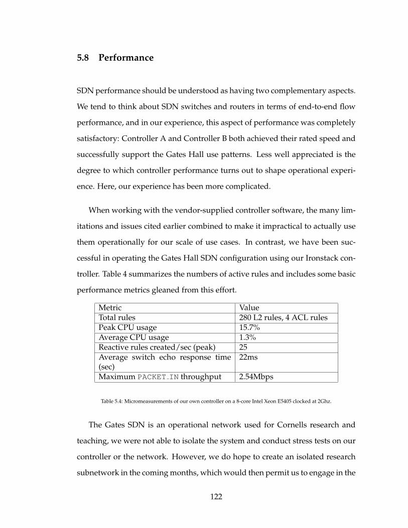
5.8 Performance
SDN performance should be understood as having two complementary aspects.
We tend to think about SDN switches and routers in terms of end-to-end flow
performance, and in our experience, this aspect of performance was completely
satisfactory: Controller A and Controller B both achieved their rated speed and
successfully support the Gates Hall use patterns. Less well appreciated is the
degree to which controller performance turns out to shape operational experi-
ence. Here, our experience has been more complicated.
When working with the vendor-supplied controller software, the many lim-
itations and issues cited earlier combined to make it impractical to actually use
them operationally for our scale of use cases. In contrast, we have been suc-
cessful in operating the Gates Hall SDN configuration using our Ironstack con-
troller. Table 4 summarizes the numbers of active rules and includes some basic
performance metrics gleaned from this effort.
Metric ValueTotal rules 280 L2 rules, 4 ACL rulesPeak CPU usage 15.7%Average CPU usage 1.3%Reactive rules created/sec (peak) 25Average switch echo response time(sec)
22ms
Maximum PACKET IN throughput 2.54Mbps
Table 5.4: Micromeasurements of our own controller on a 8-core Intel Xeon E5405 clocked at 2Ghz.
The Gates SDN is an operational network used for Cornells research and
teaching, we were not able to isolate the system and conduct stress tests on our
controller or the network. However, we do hope to create an isolated research
subnetwork in the coming months, which would then permit us to engage in the
122

form of more microbenchmarks that might shed deep light on the scalability of
our solution and the potential for deployment of SDN in networking in larger
campus configurations. The Gates Hall experience, modulo the difficulties we
had with off the shelf controller software, actually encourages us to believe that
larger SDN configurations should certainly be feasible, and our hope is to ex-
plore that option in future work.
5.9 Challenges ahead for SDN
Going forward with SDN, several important challenges remain to be addressed:
5.9.1 Switch CPU performance
The most immediate concern facing SDN technology is the disparity in com-
puting power between the switch processor and a controller. As our experience
shows, the embedded switch processor is typically undersized and is often re-
sponsible for the bottleneck between the controller and the switching fabric.
This bottleneck becomes more pronounced as successive versions of the Open-
Flow standard impose additional complexity upon the embedded processor.
5.9.2 Capacity of rule tables
Another issue facing SDN hardware is its relative scarcity of general-purpose
flow entries. Compared to traditional switches, general-purpose 12-tuple Open-
Flow rule matching consumes more expensive ternary content address memory
123

(TCAM) and therefore offers less entries for the same amount of TCAM space.
Even with recent advances in OpenFlow TCAM storage efficiencies, the num-
ber of available general-purpose entries on most switches today is generally no
more than 2000, with many switches offering less than 1000 (see Table 5). This is
an order of magnitude lesser than consumers are used to with traditional hard-
ware, and is often perceived to be a limiting factor in scaling a network. The
problem is somewhat alleviated by dedicated tables that can be used to soak
up commonly-installed flow types, however the shortage of cheap TCAM for
general-purpose OpenFlow rules will continue to be an impediment for some
time.
OpenFlow switch model Generic flow capacity Other tables availableDell S4810/20 500 L2, L3Dell N2048 896 L2, VLANNEC PF5820 750 L2Pica8 P3297 8000 L2, L3Brocade MLX 4000 L2, L3, L23
Table 5.5: OpenFlow table capacities of some equipment.
5.9.3 Non-standard behavior
While non-standard behavior is generally tolerated as vendor differences be-
tween hardware companies, the reality is that non-conformance to standards
makes it difficult for generic OpenFlow controllers to be written without intro-
ducing substantial conditional code or a complete driver layer. The increasing
number of OpenFlow hardware vendors, coupled with the growing complexity
of OpenFlow standards, increases the risk of emergent vendor-specific behavior
that can negatively impact controller development.
124
5.10 Conclusion
In this chapter, we presented our observations and findings from deploying
readily-available OpenFlow controllers on our SDN. Through operation of these
controllers, we identified a number of important issues with SDN deployment
and OpenFlow controller design. The chapter concluded with some of the chal-
lenges that continue to hinder SDN adoption at a larger scale.
125

CHAPTER 6
A NETWORK SWITCH AUGMENTATION
Our research and operational experience with existing OpenFlow network
switches left us wanting for a more sophisticated solution that is more user-
friendly. This chapter explores the idea of a network switch augmentation, a drop-
in hardware solution that can provide improved functionality and usability.
Our idealized design is shaped by our operational experience with OpenFlow
network management (chapter 5), and is heavily influenced by the desire to
support RAILS and EtherSlice (chapters 3 and 4), while being resilient and scal-
able. Most importantly, the augmentation must be simple to install and use, and
should not require hardware modifications to the OpenFlow switch.
6.1 Functional and usability deficiencies
Based on our experience with the Dell S4810 [5] high performance OpenFlow
switch, we identified the following functional and usability deficiencies:
• Poor PACKET IN performance.
• Lack of an independent computing unit to run user software.
• Difficulty in configuring the switch outside of OpenFlow.
• Lack of an NPU.
126
6.1.1 Poor PACKET IN performance
The PACKET IN mechanism is a useful channel for receiving hints about the
data plane. Besides receiving notification of flow-misses to generate reactive
flows, PACKET IN events can be used to discover underlying network state,
such as the mappings between Ethernet and IP addresses of devices. The
PACKET IN mechanism can also be combined with PACKET OUT mechanism
to simulate a controller plane presence, and can be used to implement function-
ality when data plane clients need to communicate with their controllers (see
chapter 5.6.4).
However, as our operational work in chapter 5 shows, the Dell S4810 switch
has poor performance copying packets from the data plane to the control plane,
with sustained peak bandwidths of about 2.54Mbps. This is far below the band-
width capability of the network link between the switch and controller. This
bottleneck is due to CPU saturation, and excessive PACKET IN throughput af-
fects responsiveness of other OpenFlow tasks.
6.1.2 Lack of an independent computing unit to run user soft-
ware
In the process of building the Ironstack controller, we asked ourselves how close
we could situate the controller to the actual OpenFlow hardware itself. Our key
motivation was to provide a default controller ready to run when the Open-
Flow switch was powered up, but we later generalized this desire to include
other user applications. In other words, is it possible to treat the switch as a net-
127

working equipment that also features a CPU, such that the switch can be used
as a server?
The reality was quite grim: existing OpenFlow network switches generally
lack a robust processor, and that processor is usually already dedicated to the
embedded operating system of the switch. While it is possible to modify or
replace a switch’s embedded operating system to permit the execution of user
programs, in reality most switch embedded operating systems are proprietary
and necessary for correct operation of the switch and cannot be replaced arbi-
trarily. Where it is possible to run user programs under the embedded operating
system, performance is usually poor because of the overtaxed embedded pro-
cessor.
6.1.3 Difficulty in configuring the switch outside of OpenFlow
On many OpenFlow network switches that we are aware of today, the only way
to access and modify their initial configurations is through a serial line (RS232)
interface. In particular, the Dell S4810 switch requires a lengthy configuration
step over the serial interface before the switch can be enabled for OpenFlow use.
The procedure is complicated and requires a separate computer outfitted with a
RS232 interface. The process of such configuration is usually manual, laborious
and often repetitive, yet critical for bringing the switch to an operational state.
It would be desirable for the network switch augmentation to allow automatic
rapid configuration of the OpenFlow switch with minimal labor, possibly with
the aid of human interface devices.
128

6.1.4 Lack of an NPU
NPUs, particularly FPGA-based units, are extremely flexible and useful for line-
rate packet processing. An NPU can accomplish any arbitrary computation on a
network packet, and is not constrained by the fixed-function pipelines of Open-
Flow or P4 [35]. This makes NPUs well-suited for tasks such as RAILS and
EtherSlice (see chapters 3 and 4). NPUs can thus be seen as complementary
to OpenFlow, although NPUs themselves are not generally available as built-in
components on commercial OpenFlow switches.
6.2 Network switch augmentation design
We now cover the design of our idealized network switch augmentation.
6.2.1 Hardware specifications
Our prototype augmentation is based on the single core Raspberry Pi model B+
microcontroller (RPi) [29] and is fully software and pin-compatible with its more
recent, faster multicore replacement models (Raspberry Pi 2 and Raspberry Pi
3). The RPi microcontroller is low cost ($35), compact and has a substantial num-
ber of general-purpose I/O (GPIO) pins for interfacing with external peripher-
als. Its default operating system, Raspbian, is Linux-based and well-supported
in the development community, striking parity with other Linux distributions in
terms of access to software packages, utilities, modern compilers and toolchains.
Moreover, the RPi has decent computing performance and is capable of exe-
129

cuting many modern applications that are typically associated with desktop or
server-class computing. This makes the RPi an ideal system for running the
Ironstack low-level controller. Table 6.1 compares the hardware capabilities of
select Raspberry Pi models.
Hardware Raspberry PiB+
Raspberry Pi 2 Raspberry Pi 3
SoC BroadcomBCM2835
BroadcomBCM2836
BroadcomBCM2837
CPU model ARM1176JZF-S Cortex-A7 Coretex-A53Instruction setarchitecture
32 bit ARMv6 32 bit ARMv7 32/64 bitARMv8
CPU Frequency 700Mhz 900Mhz 1.2GhzNumber ofcores
1 4 4
RAM 512MB 1GB 1GBGPIOs 17 17 17Power rating 600mA (3.0W) 800mA (4.0W) 800mA (4.0W)
Table 6.1: A comparison of pin-compatible Raspberry Pi variants for the prototype network switch augmentation.Sources: [29] [27] [28].
6.2.2 Peripherals
Our network switch augmentation features several peripherals that provide
various functionality. These are:
• 2xEthernet network interfaces.
• A USB serial-to-TTL connector.
• Bluetooth BLE4.0 transceiver.
• A capacitive touch screen.
• (Optional) A NetFPGA10G or similar card (or an array of them).
130

The schematics for the network switch augmentation can be seen in figure
6.1. The following subsections provide an explanation of how the peripherals
are used and the utility they provide.
Figure 6.1: Schematic for the network switch augmentation, including connections to the OpenFlow switch.
Ethernet network interfaces
The RPi and its successor models are manufactured with one built-in 10/100
Ethernet network interface, addressable as eth0 in the Raspbian operating sys-
tem. This primary interface provides the TCP networking connectivity required
for the local low-level Ironstack controller(s) to communicate with the Open-
Flow hardware, and is ideally connected to the management interface on the
OpenFlow hardware. The management interface on an OpenFlow switch pro-
vides a dedicated, out-of-band communications channel with the low-level con-
troller. If such a management interface is not available or if a separate control
plane network is to be used, then the primary Ethernet interface on the RPi
131

should be connected to the control network. A discussion about the tradeoffs
between different control plane designs is explored in section 7.2.
The RPi does not come outfitted with a secondary Ethernet network inter-
face, however this can be provisioned through a USB attachment. The pur-
pose of the secondary Ethernet network interface (eth1) is to improve the gen-
eral responsiveness of the overall controller/switch system. As our operational
findings in section 5.5.1 show, reducing the PACKET IN load on the embedded
switch CPU frees up cycles that results in better overall OpenFlow responsive-
ness. Instead of directing flow-miss events through the switch CPU to the con-
troller, PACKET IN events can be avoided entirely by diverting flow-miss pack-
ets to the secondary network interface on the RPi. The RPi runs a packet demul-
tiplexer daemon on this promiscuous interface that reads out the packets via an
API such as libpcap or DPDK and hands them to the appropriate low-level
controller via IPC. Figure 6.2 shows the ruleset required to divert flow-miss
packets to the secondary RPi network interface, while figure 6.3 shows how
flow-miss packets are handled at the RPi switch augmentation after they are
copied from the OpenFlow switch.
Serial-to-TTL connector
The OpenFlow specification deliberately elides discussion on the prerequisite
configuration steps required to put a switch into OpenFlow mode. At mini-
mum, an OpenFlow switch needs to be configured with a controller IP address
and port. This configuration needs to be performed out-of-band, and is typ-
ically provided via a Cisco IOS-like [3] command line interface. On the Dell
S4810/4820 switches that we built our controllers for, the command line inter-
132

Figure 6.2: A low priority rule captures all flow-miss packets and redirects them through a data plane port to eth1 onthe switch augmentation. If VLANs are used on the switch, this data plane port must be a tagged member of all suchVLANs.
face can be unconditionally accessed via the 9600 baud RS232 serial port con-
nector.
Our RPi network switch augmentation thus features a serial port connector
from the microcontroller to the switch. Because the switch serial port uses the
RS232 electrical standard (-12V to +12V signals) and the RPi uses TTL (3.3V and
0V levels), a serial-to-TTL converter is required. For simplicity, we use a USB
serial-to-TTL device, which conveniently appears as a file in Raspbian under
/dev/ttyS1. An additional advantage of our setup is that the USB device we
used has a connector that fits the switch’s unusual RJ45 serial port.
A serial configurator process on our RPi switch augmentation assumes sole
control of the serial port and provides a RPC interface for other processes to
query or control the hardware. This process translates RPC commands to the
Cisco IOS-like commands that are then sent via serial, and interprets the result-
ing responses. The process also performs arbitration, notification and mediation
for processes that wish to simultaneously control or configure the hardware.
133

Figure 6.3: Flow miss packets are forwarded to eth1 on the switch augmentation and demultiplexed to the appropriatelow-level controller instance.
Several processes interface with the serial command process. For example,
the human interface process converts touchscreen commands to configuration
RPC calls. Figure 6.4 shows the relationship between the various processes that
interface with the serial configurator. When interfacing with a switch that has
been reset to factory settings, the RPi switch augmentation automatically uses
the serial configurator to put the switch into a default SDN learning switch with
one low-level controller instance. This allows an operator to rapidly deploy an
OpenFlow switch by connecting it to the RPi switch augmentation.
Bluetooth BLE4.0 transceiver
While not a critical component, our augmentation also includes a Bluetooth Low
Energy transceiver. The transceiver is used to provide out-of-band proximity ac-
cess to the augmentation and can be used to interface with a Bluetooth-enabled
device so the switch may be configured without physically accessing it. Future
134

Figure 6.4: The serial configurator process provides arbitration, notification and mediation for actual OpenFlow hard-ware settings.
work may leverage this device to provide out-of-band mesh connectivity among
low-level controllers within the same physical area.
Capacitive touch screen
A key portion of our work aims to provide improved usability. Our augmen-
tation features an integrated capacitive touch panel to provide monitoring and
hands-on configuration of the various operating parameters of the local low-
level controller(s) and OpenFlow hardware. This removes the need to sepa-
rately setup and configure the hardware and controller, and relieves the opera-
tor of the burden of having to sift through expansive manuals for the Cisco-IOS
commands to activate hardware features.
135

The touch panel screen is also capable of simplifying tasks that were previ-
ously laborious. For example, cable tracing in a data center can be rapidly expe-
dited by having the operator indicate on the touch panel the desired switch port
whose cable needs to be traced. The touch panel control module issues an RPC
to the relevant low-level controller, which then injects a special marker packet
out the switch port. On receipt of the marker packet at the remote switch, the
remote network switch augmentation can perform a task (such as flashing its
screen or an LED) to indicate the trace endpoint.
NetFPGA add-in
Experience from our RAILS and EtherSlice (chapters 3 and 4) work show that
the NetFPGA can be a very useful platform for providing reconfigurable NPU
operations that are otherwise difficult to perform with OpenFlow, P4 [35] or re-
lated fixed-function networking hardware. Our RPi switch augmentation can
be optionally augmented with an array of NetFPGA cards. The NetFPGA cards
communicate with the RPi via I2C (or CAN), with each NetFPGA card holding
a unique I2C/CAN address. The NetFPGA control module on the RPi detects
the number and type of FPGA modules available, and coordinates with the low-
level controller(s) to determine the appropriate rules to install when NPU sup-
port is required. Figure 6.5 shows one way in which an array of NetFPGAs can
be attached to the RPi switch augmentation.
With this setup, low-level controllers can reserve/deallocate NetFPGA com-
putation units, assign path meta-addresses, request reorder/deduplication
buffers and so on, without manual intervention.
136

Figure 6.5: An array of NetFPGAs using shared I2C communication lines.
6.3 Integration with a switch
Although designed as an independent external unit, the network switch aug-
mentation can also be built as an integral part of an OpenFlow switch, thus re-
moving the need for additional space, wiring and power for the augmentation
itself.
6.4 Conclusion
In this chapter, we unveiled the design and engineering schematics of a network
switch augmentation. The network switch augmentation combines many dis-
parate elements in a coherent manner to provide a turnkey solution that offers
RAILS, EtherSlice and Ironstack in a single package, while being convenient and
137

user-friendly. Our network switch augmentation can be retrofitted onto existing
OpenFlow switches, or built within the switches itself.
138

CHAPTER 7
IRONSTACK SOFTWARE DESIGN
In this chapter, we describe the design and architecture of our Ironstack Open-
Flow controller system. This system was written in C++ and built to meet Open-
Flow 1.0 specifications (at system conception, hardware support for OpenFlow
1.3 was not yet available). In the course of our research, we adapted the soft-
ware several times for various experiments (notably for RAILS and EtherSlice
as described in prior chapters). The system presented here represents the ’base’
version, which is the generic learning switch controller that was accepted for
deployment onto the Gates Hall software-defined network.
As alluded to in section 5.6.1, our OpenFlow controller is hierarchical by de-
sign and includes special support hardware. The term ’Ironstack’ does not refer
to a single entity, computer process or software. Rather, it is an aggregate term
that addresses all our proprietary software and hardware solutions deployed to
drive an SDN.
7.1 General architectural features
The Ironstack controller can be coarsely broken down into several key compo-
nents:
• Bootstrap agent
• Hardware abstraction layer (HAL)
• Packet callback chain
139

• Services (CAM/ARP/flow table, security policy/switch state etc)
Figure 7.1 shows the general architectural features of the Ironstack system.
Figure 7.1: Ironstack components.
7.1.1 Bootstrap agent
The bootstrap agent is the first significant module to run in the startup phase of
the controller. The role of this module is to discover switch configuration set-
tings that may not be available or discoverable from OpenFlow itself; hence it
needs to run before OpenFlow-specific code is started. The bootstrap agent con-
nects to the management system over telnet and downloads its configuration in
a read-only manner. In the process, it identifies global switch settings such as
the number of OpenFlow instances, their respective controller connection ad-
dresses and ports, as well as the VLAN configuration of each individual port
in an OpenFlow instance. This information is critical to the correct operation
140

of the OpenFlow controller, since the controller needs the switch to connect at
the correct address, and must also know the specific VLANs on the ports of its
managed instance.
Apart from low-level configuration detection, the bootstrap agent also pro-
vides direct access to switch OS utilities that are not available through Open-
Flow. For example, on our Dell S4810 switch, the bootstrap agent is capable of
changing OpenFlow-specific settings (such as the port/address, echo/timeout
interval) and performing some actions that are not possible from OpenFlow it-
self (such as configuring ACL table depths, toggling L2/L3 tables and power
cycling the switch).
7.1.2 Hardware abstraction layer
The hardware abstraction layer (HAL) represents the lowest layer of the con-
troller and interfaces directly with the switch hardware through the OpenFlow
protocol. The HAL is responsible for a number of hardware-specific tasks,
including handshaking, heartbeat acknowledgements and filtering of Open-
Flow messages for the relevant service modules. It is architected for perfor-
mance and uses dedicated threads to service the input and output communi-
cation queues, as well as two separate threads to handle event callbacks and
PACKET IN events. Thus, event or packet processing speeds are independent
of I/O and may proceed at separate rates without affecting one another. Figure
7.2 shows the processing pipeline of the HAL.
HAL exposes a publish/subscribe model, and interested subunits can make
API calls to it for notifications of an event. For example, the flow service module
141

subscribes to HAL for messages that indicate flow modification or flow deletion,
and the operations module subscribes to HAL for messages pertaining to flow
statistics. Events are processed sequentially by the dedicated event handling
thread, and an event must be fully processed (returned from the callback) before
the next event can be considered.
PACKET IN messages are data-plane specific and can be quite numerous at
any instant. HAL filters these messages into a separate queue, which is han-
dled by another dedicated thread, so that PACKET IN messages do not affect
the processing speed of other switch-related events. PACKET IN messages en-
ter a packet callback chain where they are processed sequentially.
7.1.3 Packet callback chain
Packets may be copied to a Ironstack low-level controller via the PACKET IN
mechanism for a variety of reasons, such as on flow miss events or when manu-
ally specified by higher-level application logic. For example, the L2/L3 learning
unit snoops on received packets to recover Ethernet-to-IP mappings of hosts on
the network; an echo daemon may respond to pings, or a controller-based ap-
plication level TCP module may simulate a TCP communications stack by re-
sponding to TCP packets (see section 5.6.4). Raw, unfiltered packets may also
arrive at a low-level controller via IPC when conveyed through a packet demul-
tiplexer operating on the secondary Ethernet interface (eth1) of the support
hardware (see section 6.2.2).
In every use case, it is clear that some principled way of filtering and deliver-
ing the packets must be followed. The method used in our Ironstack controller
142

Figure 7.2: HAL processing pipeline. Dotted boxes represent processing boundaries of the various HAL threads.
follows the chain of responsibility software design pattern, where multiple listen-
ers can subscribe to callbacks that are activated when a packet is available. Call-
backs are registered with HAL together with a priority level. The priority level
determines the precedence in which callbacks are activated. When a packet is
received, it is sent down the callback chain for consideration by the registered
entity with the highest priority. If that callback consumes the packet, the remain-
der of the callback chain is ignored and they do not receive the packet. Other-
wise the packet continues propagation down the callback chain to the entity
with the next highest priority. Note that a callback may transparently inspect a
packet and take action without consuming the packet; this feature is exploited
143

in L2/L3 learning functionality of the default controller. Packets not consumed
by any callback are dropped when they reach the end of the chain. Figure 7.3
gives a pictorial representation of the callback chain.
Figure 7.3: Packet callback chain.
7.1.4 Services
Although the HAL is capable of sustaining an OpenFlow connection on its own,
the ’controller’ aspect of Ironstack arises from its interaction with services. Ser-
vices represent self-contained, highly specialized logic suited for a narrow set of
144

related tasks, and may subscribe to specific HAL OpenFlow messages. For ex-
ample, the switch state service subscribes to port modification events, and inter-
acts with HAL to maintain an authoritative view of the local OpenFlow switch.
This view includes information about the equipment serial number, per-port
link activities, link speeds, VLAN associations and VLAN tagging information.
Because it is a service, higher-level application logic can query the switch state
module for this information; the HAL does not maintain it.
Services are ’hot-pluggable’ and can be attached or detached from the HAL
at runtime. A service catalog maintains the necessary smart pointers to these
modules.
7.2 Inter-Ironstack communications
To realize the goal of resilience and scalability, the Ironstack low-level con-
trollers are architecturally distributed and non-dependent on a centralized en-
tity. Each low-level controller instance maps to a single OpenFlow switch in-
stance, and is capable of making independent forwarding decisions. Low-level
controllers synchronize state via gossip and are also able to requisition flow
services from one another, such that a single low-level controller can request
end-to-end setup or teardown of flows in a network.
The enabling primitive for this distributed operation is a form of inter-
Ironstack communications. Inter-Ironstack communications may be done in-
band or out-of-band depending on the architecture of the SDN; each approach
has its tradeoffs which are discussed in the following subsections. Table 7.1
summarizes the key points.
145

7.2.1 Dedicated control network
On many SDN setups, particularly SDNs that are architected for a centralized
controller or distributed data store, a dedicated network is provisioned for con-
trol plane communications. The Gates Hall SDN follows such a setup. Under
this design, the low-level controllers may be located anywhere, possibly on re-
mote machines far away from the physical switch itself. Because the low-level
controllers run on a unified network, they may communicate with one another
conveniently via control-plane IP addressing, out-of-band from the data plane
network. This arrangement is also resource-efficient in that a large number of
low-level controllers can be run on a single powerful server, or arbitrarily dis-
tributed over multiple machines as the OpenFlow network is scaled.
One disadvantage of such SDN architecture is that the failure or degradation
of equipment on the control plane network, such as due to heavy load or an out-
age of an aggregation switch serving multiple OpenFlow switches, may result
in the loss of responsiveness or operation of the affected OpenFlow switches.
Such architecture is also incompatible with the efficient PACKET IN handling
mechanism discussed in section 6.2.2, as it is infeasible to outfit a server with
many spare Ethernet interfaces and cables. By the same reasoning, it is also
infeasible to provide the pre-OpenFlow configuration support as discussed in
section 6.2.2. NetFPGA support (section 6.2.2) would have to be implemented
in a different way, possibly by having the NetFPGA parse instructions received
directly from its network ports, as opposed to I2C/CAN communication from
a dedicated support hardware.
Figure 7.4 shows an example of an SDN using a separate control plane net-
work.
146

Figure 7.4: An SDN with a separate control plane network. Control plane elements are shaded in gray. One OpenFlowswitch has been magnified for clarity.
7.2.2 In-band control network
On large SDN deployments, the cost of the independent control network may
become quite substantial as additional separate cabling and switches are needed
beyond the SDN data plane requirements. For this reason, it may be more cost-
efficient to consider a deployment of low-level controllers as described in sec-
tion 5.6.1. Such a deployment also lends more naturally to the provision of
high efficiency PACKET IN streaming, pre-OpenFlow configuration and NetF-
PGA support as detailed in section 6. As an advantage, the failure of any single
element in the SDN is localized, and non-failed switches continue to operate
without disruption. This is in contrast to a separate control network, where the
failure of a single control network component can cause multiple disruptions in
connectivity between OpenFlow switches and their controllers.
147

The disadvantage with such a deployment is that multiple independent
physical servers are required, one for each switch, even if the servers them-
selves can be small and cheap. The cost of the servers, as well as their space and
power requirements, may mitigate any savings associated with eliminating the
control network. It also makes conversion to the out-of-band model impossi-
ble, as the underlying infrastructure for the independent control network does
not exist. Furthermore, because the low-level controllers are no longer on the
same unified control network, it is not possible for them to communicate using
regular IP communication primitives. Instead, the low-level controllers have to
rely on the underlying data plane to transport control-plane messages, embed-
ding such messages in-band with data plane traffic. A proposed mechanism for
doing so is discussed in section 3.3.1.
7.3 Conclusion
In this chapter, we presented the core modular components of our Ironstack
controller software in detail, described its bootstrap process, and detailed its
distributed operation. We also presented alternative designs for the control net-
work, and compared the tradeoffs inherent to each design. Finally, we described
how our Ironstack controller can be adapted to run on these control network de-
signs.
148

Property Dedicated control planenetwork
In-band control plane net-work
Failure han-dling
Single failures can causemultiple outages
Single failures cause atmost one failure
Effect of con-gestion
Congestion on controlplane network can causeslowdown
Congestion on data planenetwork can cause slow-down
Controllerplacement
Flexible; anywhere as longas it is on the control net-work
Close proximity to Open-Flow switch
Convertibility Can be converted to in-band control network eas-ily
Costly to convert to ded-icated control plane net-work
Supports cen-tralized con-troller
Yes No
Supports dis-tributed con-troller
Yes Yes
Support forpre-OpenFlowoperations
No Yes
NetFPGA sup-port
Yes Yes
High efficiencyPACKET INhandling
No Yes
Cost Primarily from switchesand cables for controlplane network
Primarily from distributedserver boxes
Table 7.1: SDN control plane architecture tradeoffs.
149

CHAPTER 8
FUTURE WORK
While our RAILS work investigated the use of multiple paths to improve per-
formance and reliability, it is unclear how our system performs beside other
popular multipath techniques such as MPTCP. Specifically, it would be inter-
esting to compare the behavior of regular TCP over RAILS to MPTCP over a
similar network setup, and compare their respective behaviors under failure.
This is one subject of our future work.
Our current EtherSlice work depends on simulation and uses an inefficient
controller-based NPU. We believe that the current processing pipeline does not
realize its full performance potential because it is entirely software-based and
unaccelerated by any hardware. A better implementation would use a real
OpenFlow switch coupled with a hardware-based NPU such as the NetFPGA
that we used in RAILS. Alternatively, a hardware OpenFlow switch together
with a software-based NPU that combines fast packet I/O (using a frame-
work such as NetMap) with GPU-based matrix computation, might attain a
respectable EtherSlice throughput at a fraction of the cost and implementation
difficulty of the NetFPGA approach. Both are targets of our future work.
Finally, we note that our Ironstack controller is still a work in progress. While
we were able to improve various performance and usability aspects of an SDN
to the point where it is capable of driving an operational SDN, it is presently a
system with many rough edges and unimplemented features. For example, the
Ironstack controller lacks a global coordinating entity, a policy language, and a
means to adequately address certain common security concerns that may arise
150

from abuse of an SDN. These are rich targets for future work, and we plan to
refine our controller such as is befitting for a commercial setting.
151

CHAPTER 9
CONCLUSION
In this thesis, we presented a number of engineering solutions designed to ad-
dress real needs in the IoT space. We showed that problems pertaining to per-
formance, reliability and security can be tackled through a combination of SDN
switches, NPUs and appropriate packet processing. RAILS solves the problem
of performance and assurance for IoT devices, while EtherSlice retrofits confi-
dentiality and anonymity for devices that are incapable of them.
Because RAILS and EtherSlice depended significantly on the use of an SDN
and an SDN controller, we also investigated and presented our experience with
configuring, operating and maintaining a real, operational SDN. The lessons
learnt enlightened our controller design, and we introduced the design and soft-
ware architecture of the resulting system.
Finally, drawing on all the lessons we learnt from RAILS, EtherSlice and
Ironstack, we engineered a network switch augmentation that combines all
three systems into a box that can be quickly and conveniently deployed. It is
our hope that our combined solution would be a practical product for IoT net-
work operators such as the power grid.
152

BIBLIOGRAPHY
[1] Armadillo: C++ linear algebra library. http://arma.sourceforge.net/.
[2] Big Network Controller. http://bigswitch.com/products/SDN-Controller.
[3] Cisco IOS Technologies. http://www.cisco.com/c/en/us/products/ios-nx-os-software/ios-technologies/index.html.
[4] Data Plane Development Kit. http://dpdk.org/.
[5] Dell S4810 high performance SDN switch. https://www.dell.com/learn/us/en/04/shared-content˜data-sheets˜en/documents˜dell_force10_s4810_spec_sheet.pdf.
[6] Dell S4810/Z9000 Software-Defined Networking Deployment GuideVersion 1.0. https://www.force10networks.com/CSPortal20/KnowledgeBase/DOCUMENTATION/InstallGuidesQuickrefs/SDN/SDN_Deployment_1.0_28-Feb-2013.pdf.
[7] Ericsson SDN Controller. https://www.sdxcentral.com/products/ericsson-sdn-controller/.
[8] Ethernet Evolves Again To Meet the Internet-of-Things.http://electronicdesign.com/communications/ethernet-evolves-again-meet-internet-things.
[9] Floodlight OpenFlow controller. http://www.projectfloodlight.org/floodlight/.
[10] Hacking into Internet Connected Light Bulbs.http://www.contextis.com/resources/blog/hacking-internet-connected-light-bulbs/.
[11] HP Internet of things research study 2015. http://www8.hp.com/h20195/V2/GetPDF.aspx/4AA5-4759ENW.pdf.
[12] IEEE 802 numbers, Ether Types. http://standards.ieee.org/develop/regauth/ethertype/eth.txt.
153
[13] IEEE 802.1-AX 2008. Link Aggregation, IEEE 2008.
[14] IEEE 802.1D-2004. Media Access Control (MAC) Bridges, IEEE 2004.
[15] IEEE 802.1Q-2011. VLAN Bridges, IEEE 2011.
[16] IEEE 802.1Qbp. Equal Cost Multiple Paths, IEEE 2014.
[17] IEEE Standard for a Precision Clock Synchronization Protocol for Net-worked Measurement and Control Systems. https://standards.ieee.org/findstds/standard/1588-2008.html.
[18] Internet of Things Global Standards Initiative.
[19] Mininet: An Instant Virtual Network on your Laptop (or other PC). http://mininet.org/.
[20] NEC ProgrammableFlow PF6800 controller. http://www.necam.com/sdn/doc.cfm?t=PFlowController.
[21] NetFPGA. http://netfpga.org/.
[22] Open vSwitch. http://openvswitch.org/.
[23] OpenDaylight Project. https://www.opendaylight.org/.
[24] Organizationally Unique Identifiers. http://standards-oui.ieee.org/oui.txt.
[25] PF RING, High-speed packet capture, filtering and analysis. http://www.ntop.org/products/packet-capture/pf_ring/.
[26] POX. http://www.noxrepo.org/pox/about-pox/.
[27] Raspberry Pi 2. https://www.raspberrypi.org/blog/raspberry-pi-2-on-sale/.
[28] Raspberry Pi 3. https://www.raspberrypi.org/blog/raspberry-pi-3-on-sale/.
[29] Raspberry Pi Model B+. https://www.raspberrypi.org/products/model-b-plus/.
154

[30] Summary: Top 10 Global Survey Results, CiscoConnected World Technology Report on Big Data.http://www.cisco.com/c/dam/en/us/solutions/enterprise/connected-world-technology-report/Top-10-Survey-Results-CCWTR-Big-Data.pdf.
[31] Understanding Rapid Spanning Tree Protocol (802.1w). http://www.cisco.com/c/en/us/support/docs/lan-switching/spanning-tree-protocol/24062-146.html.
[32] Mohammad Al-Fares, Sivasankar Radhakrishnan, Barath Raghavan, Nel-son Huang, and Amin Vahdat. Hedera: Dynamic flow scheduling for datacenter networks. In Proceedings of the 7th USENIX Conference on NetworkedSystems Design and Implementation, NSDI’10, pages 19–19, Berkeley, CA,USA, 2010. USENIX Association.
[33] George Apostolopoulos. Using multiple topologies for ip-only protectionagainst network failures: A routing performance perspective. ICSFORTH,Greece, Tech. Rep, 2006.
[34] Pankaj Berde, Matteo Gerola, Jonathan Hart, Yuta Higuchi, MasayoshiKobayashi, Toshio Koide, Bob Lantz, Brian O’Connor, Pavlin Radoslavov,William Snow, et al. ONOS: towards an open, distributed SDN OS. InProceedings of the third workshop on Hot topics in software defined networking,pages 1–6. ACM, 2014.
[35] Pat Bosshart, Dan Daly, Glen Gibb, Martin Izzard, Nick McKeown, JenniferRexford, Cole Schlesinger, Dan Talayco, Amin Vahdat, George Varghese,et al. P4: Programming protocol-independent packet processors. ACMSIGCOMM Computer Communication Review, 44(3):87–95, 2014.
[36] Martin Casado, Michael J Freedman, Justin Pettit, Jianying Luo, Nick McK-eown, and Scott Shenker. Ethane: taking control of the enterprise. In ACMSIGCOMM Computer Communication Review, volume 37, pages 1–12. ACM,2007.
[37] David Chaum. The dining cryptographers problem: Unconditional senderand recipient untraceability. Journal of cryptology, 1(1):65–75, 1988.
[38] David L Chaum. Untraceable electronic mail, return addresses, and digitalpseudonyms. Communications of the ACM, 24(2):84–90, 1981.
155

[39] Henry Corrigan-Gibbs, Dan Boneh, and David Mazieres. Riposte: Ananonymous messaging system handling millions of users. In 2015 IEEESymposium on Security and Privacy, pages 321–338. IEEE, 2015.
[40] Andrew R Curtis, Jeffrey C Mogul, Jean Tourrilhes, Praveen Yalagandula,Puneet Sharma, and Sujata Banerjee. Devoflow: scaling flow managementfor high-performance networks. In ACM SIGCOMM Computer Communi-cation Review, volume 41, pages 254–265. ACM, 2011.
[41] Roger Dingledine, Nick Mathewson, and Paul Syverson. Tor: The second-generation onion router. Technical report, DTIC Document, 2004.
[42] Advait Dixit, Fang Hao, Sarit Mukherjee, TV Lakshman, and RamanaKompella. Towards an elastic distributed SDN controller. In ACM SIG-COMM Computer Communication Review, volume 43, pages 7–12. ACM,2013.
[43] Chip Elliott. GENI-global environment for network innovations. In LCN,page 8, 2008.
[44] Khaled Elmeleegy and Alan L Cox. Etherproxy: Scaling Ethernet by sup-pressing broadcast traffic. In INFOCOM 2009, IEEE, pages 1584–1592. IEEE,2009.
[45] A. Ford, C. Raiciu, M. Handley, and O. Bonaventure. Tcp extensions formultipath operation with multiple addresses. RFC 6824, RFC Editor, Jan-uary 2013. http://www.rfc-editor.org/rfc/rfc6824.txt.
[46] Michael J Freedman and Robert Morris. Tarzan: A peer-to-peer anonymiz-ing network layer. In Proceedings of the 9th ACM conference on Computer andcommunications security, pages 193–206. ACM, 2002.
[47] Sharad Goel, Mark Robson, Milo Polte, and Emin Sirer. Herbivore: A scal-able and efficient protocol for anonymous communication. Technical re-port, Cornell University, 2003.
[48] Dongsu Han, Ashok Anand, Aditya Akella, and Srinivasan Seshan. RPT:Re-architecting loss protection for content-aware networks. In Presented aspart of the 9th USENIX Symposium on Networked Systems Design and Imple-mentation (NSDI 12), pages 71–84, 2012.
156

[49] Sangjin Han, Keon Jang, Aurojit Panda, Shoumik Palkar, Dongsu Han, andSylvia Ratnasamy. SoftNIC: A software NIC to augment hardware. InTechnical Report UCB/EECS-2015-155. EECS Department, University of Cal-ifornia, Berkeley, 2015.
[50] Sangjin Han, Keon Jang, KyoungSoo Park, and Sue Moon. PacketShader:a GPU-accelerated software router. In ACM SIGCOMM Computer Commu-nication Review, volume 40, pages 195–206. ACM, 2010.
[51] Jiayue He and Jennifer Rexford. Toward Internet-wide Multipath Routing.Network, IEEE, 22(2):16–21, 2008.
[52] Danny Yuxing Huang, Kenneth Yocum, and Alex C Snoeren. High-fidelityswitch models for software-defined network emulation. In Proceedings ofthe second ACM SIGCOMM workshop on Hot topics in software defined net-working, pages 43–48. ACM, 2013.
[53] Sushant Jain, Alok Kumar, Subhasree Mandal, Joon Ong, Leon Poutievski,Arjun Singh, Subbaiah Venkata, Jim Wanderer, Junlan Zhou, Min Zhu, et al.B4: Experience with a globally-deployed software defined WAN. In ACMSIGCOMM Computer Communication Review, volume 43, pages 3–14. ACM,2013.
[54] Naga Katta, Haoyu Zhang, Michael Freedman, and Jennifer Rexford. Ra-vana: Controller fault-tolerance in software-defined networking. In Pro-ceedings of the 1st ACM SIGCOMM Symposium on Software Defined Network-ing Research, page 4. ACM, 2015.
[55] Sachin Katti, Dina Katabi, and Katarzyna Puchala. Slicing the onion:Anonymous routing without PKI. 2005.
[56] Hyojoon Kim, Mike Schlansker, Jose Renato Santos, Jean Tourrilhes, YoshioTurner, and Nick Feamster. CORONET: Fault Tolerance for Software De-fined Networks. In 2012 20th IEEE International Conference on Network Pro-tocols (ICNP), pages 1–2. IEEE, 2012.
[57] Eddie Kohler, Robert Morris, Benjie Chen, John Jannotti, and M FransKaashoek. The Click modular router. ACM Transactions on Computer Sys-tems (TOCS), 18(3):263–297, 2000.
[58] Teemu Koponen, Martin Casado, Natasha Gude, Jeremy Stribling, LeonPoutievski, Min Zhu, Rajiv Ramanathan, Yuichiro Iwata, Hiroaki Inoue,
157

Takayuki Hama, et al. Onix: A Distributed Control Platform for Large-scale Production Networks. In OSDI, volume 10, pages 1–6, 2010.
[59] Alexandros Kostopoulos, Henna Warma, T Leva, Bernd Heinrich, AlanFord, and Lars Eggert. Towards multipath TCP adoption: challenges andopportunities. In Next Generation Internet (NGI), 2010 6th EURO-NF Confer-ence on, pages 1–8. IEEE, 2010.
[60] Diego Kreutz, Fernando MV Ramos, Paulo Esteves Verissimo, Christian Es-teve Rothenberg, Siamak Azodolmolky, and Steve Uhlig. Software-definednetworking: A comprehensive survey. Proceedings of the IEEE, 103(1):14–76,2015.
[61] Maciej Kuzniar, Peter Peresini, and Dejan Kostic. What you need to knowabout SDN control and data planes. Technical report, 2014.
[62] Ralph Langner. Stuxnet: Dissecting a cyberwarfare weapon. IEEE Security& Privacy, 9(3):49–51, 2011.
[63] Dan Levin, Andreas Wundsam, Brandon Heller, Nikhil Handigol, andAnja Feldmann. Logically centralized? State distribution trade-offs in soft-ware defined networks. In Proceedings of the first workshop on Hot topics insoftware defined networks, pages 1–6. ACM, 2012.
[64] Guohan Lu, Rui Miao, Yongqiang Xiong, and Chuanxiong Guo. Using cpuas a traffic co-processing unit in commodity switches. In Proceedings of thefirst workshop on Hot topics in software defined networks, pages 31–36. ACM,2012.
[65] King-Shan Lui, Whay Chiou Lee, and Klara Nahrstedt. STAR: a transpar-ent spanning tree bridge protocol with alternate routing. ACM SIGCOMMComputer Communication Review, 32(3):33–46, 2002.
[66] Tudor Marian, Ki Suh Lee, and Hakim Weatherspoon. Netslices: scal-able multi-core packet processing in user-space. In Proceedings of the eighthACM/IEEE symposium on Architectures for networking and communicationssystems, pages 27–38. ACM, 2012.
[67] Ilias Marinos, Robert NM Watson, and Mark Handley. Network stack spe-cialization for performance. In ACM SIGCOMM Computer CommunicationReview, volume 44, pages 175–186. ACM, 2014.
158

[68] Nick McKeown, Tom Anderson, Hari Balakrishnan, Guru Parulkar, LarryPeterson, Jennifer Rexford, Scott Shenker, and Jonathan Turner. Openflow:enabling innovation in campus networks. ACM SIGCOMM Computer Com-munication Review, 38(2):69–74, 2008.
[69] Hesham Mekky, Fang Hao, Sarit Mukherjee, Zhi-Li Zhang, and TV Lak-shman. Application-aware data plane processing in sdn. In Proceedings ofthe third workshop on Hot topics in software defined networking, pages 13–18.ACM, 2014.
[70] Murtaza Motiwala, Megan Elmore, Nick Feamster, and Santosh Vempala.Path splicing. In ACM SIGCOMM Computer Communication Review, vol-ume 38, pages 27–38. ACM, 2008.
[71] Jayaram Mudigonda, Praveen Yalagandula, Mohammad Al-Fares, and Jef-frey C Mogul. SPAIN: COTS Data-Center Ethernet for Multipathing overArbitrary Topologies. In NSDI, pages 265–280, 2010.
[72] Rajesh Narayanan, Saikrishna Kotha, Geng Lin, Aimal Khan, Sajjad Rizvi,Wajeeha Javed, Hassan Khan, and Syed Ali Khayam. Macroflows and mi-croflows: Enabling rapid network innovation through a split SDN dataplane. In Software Defined Networking (EWSDN), 2012 European Workshopon, pages 79–84. IEEE, 2012.
[73] Rajesh Narayanan, Geng Lin, Affan A Syed, Saad Shafiq, and Fahd Gilani.A framework to rapidly test SDN use-cases and accelerate middlebox ap-plications. In Local Computer Networks (LCN), 2013 IEEE 38th Conference on,pages 763–770. IEEE, 2013.
[74] ONF. OpenFlow switch specification 1.5.0. https://www.opennetworking.org/images/stories/downloads/sdn-resources/onf-specifications/openflow/openflow-switch-v1.5.0.noipr.pdf.
[75] John Ousterhout, Parag Agrawal, David Erickson, Christos Kozyrakis, Ja-cob Leverich, David Mazieres, Subhasish Mitra, Aravind Narayanan, GuruParulkar, Mendel Rosenblum, et al. The case for RAMClouds: scalablehigh-performance storage entirely in DRAM. ACM SIGOPS Operating Sys-tems Review, 43(4):92–105, 2010.
[76] David A Patterson, Garth Gibson, and Randy H Katz. A case for redundantarrays of inexpensive disks (RAID), volume 17. ACM, 1988.
159

[77] Mark Reitblatt, Marco Canini, Arjun Guha, and Nate Foster. Fattire:Declarative fault tolerance for software-defined networks. In Proceedingsof the second ACM SIGCOMM workshop on Hot topics in software defined net-working, pages 109–114. ACM, 2013.
[78] Luigi Rizzo. Netmap: a novel framework for fast packet I/O. In 21stUSENIX Security Symposium (USENIX Security 12), pages 101–112, 2012.
[79] Charalampos Rotsos, Nadi Sarrar, Steve Uhlig, Rob Sherwood, and An-drew W Moore. OFLOPS: An open framework for OpenFlow switch eval-uation. In Passive and Active Measurement, pages 85–95. Springer, 2012.
[80] Rob Sherwood, Glen Gibb, Kok-Kiong Yap, Guido Appenzeller, MartinCasado, Nick McKeown, and Guru Parulkar. Flowvisor: A network vir-tualization layer. OpenFlow Switch Consortium, Tech. Rep, 2009.
[81] Jeremy Stribling, Yair Sovran, Irene Zhang, Xavid Pretzer, Jinyang Li,M Frans Kaashoek, and Robert Morris. Flexible, Wide-Area Storage forDistributed Systems with WheelFS. In NSDI, volume 9, pages 43–58, 2009.
[82] Zhiyuan Teo, Vera Kutsenko, Ken Birman, and Robbert van Renesse. Iron-Stack: Performance, Stability and Security for Power Grid Data Networks.In 1st International Workshop on Trustworthiness of Smart Grids, 2014.
[83] Patricia Thaler, Norman Finn, Don Fedyk, Glenn Parsons, and Eric Gray.Ieee 802.1 q. 2013.
[84] Amin Tootoonchian and Yashar Ganjali. Hyperflow: A distributed controlplane for openflow. In Proceedings of the 2010 internet network managementconference on Research on enterprise networking, pages 3–3, 2010.
[85] Jelle Van Den Hooff, David Lazar, Matei Zaharia, and Nickolai Zeldovich.Vuvuzela: Scalable private messaging resistant to traffic analysis. In Pro-ceedings of the 25th Symposium on Operating Systems Principles, pages 137–152. ACM, 2015.
[86] Rolf Winter, Michael Faath, and Andreas Ripke. Multipath tcp sup-port for single-homed end-systems. Internet-Draft draft-wr-mptcp-single-homed-05, IETF Secretariat, July 2013. http://www.ietf.org/internet-drafts/draft-wr-mptcp-single-homed-05.txt.
160

[87] David Isaac Wolinsky, Henry Corrigan-Gibbs, Bryan Ford, and AaronJohnson. Dissent in numbers: Making strong anonymity scale. In Pre-sented as part of the 10th USENIX Symposium on Operating Systems Designand Implementation (OSDI 12), pages 179–182, 2012.
[88] Minlan Yu, Andreas Wundsam, and Muruganantham Raju. Nosix: Alightweight portability layer for the sdn os. ACM SIGCOMM ComputerCommunication Review, 44(2):28–35, 2014.
[89] Minlan Yu, Yung Yi, Jennifer Rexford, and Mung Chiang. Rethinking vir-tual network embedding: substrate support for path splitting and migra-tion. ACM SIGCOMM Computer Communication Review, 38(2):17–29, 2008.
161