overcurrent protection / 7sj62mahdniro.com/wp-content/uploads/2019/10/7sj62... · overcurrent...
TRANSCRIPT
Overcurrent Protection / 7SJ62SIPROTEC 7SJ62 multifunction protection relay
5/25Siemens SIP · Edition No. 8
Protection functions (continued)
• Inrush restraint
• Motor protection
• Overload protection
• Temperature monitoring
• Under-/overvoltage protection
• Under-/overfrequency protection
• Rate-of-frequency-change protection
• Power protection (e.g. reverse, factor)
• Undervoltage controlled reactive power protection
• Breaker failure protection
• Negative-sequence protection
• Phase-sequence monitoring
• Synchro-check
• Fault locator
• Lockout
• Auto-reclosure
Control functions/programmable logic
• Commands f. ctrl of CB and of isolators
• Position of switching elements is shown on the graphic display
• Control via keyboard, binary inputs, DIGSI 4 or SCADA system
• User-defi ned logic with CFC (e.g. interlocking)
Monitoring functions
• Operational measured values V, I, f
• Energy metering values Wp, Wq
• Circuit-breaker wear monitoring
• Slave pointer
• Trip circuit supervision
• Fuse failure monitor
• 8 oscillographic fault records
• Motor statistics
Communication interfaces
• System interface– IEC 60870-5-103 / IEC 61850– PROFIBUS DP– DNP 3/DNP3 TCP/MODBUS RTU– PROFINET
• Service interface for DIGSI 4 (modem)
• Front interface for DIGSI 4
• Time synchronization via IRIG B/DCF77
Hardware
• 4 current transformers
• 3/4 voltage transformers
• 8/11 binary inputs
• 8/6 output relays
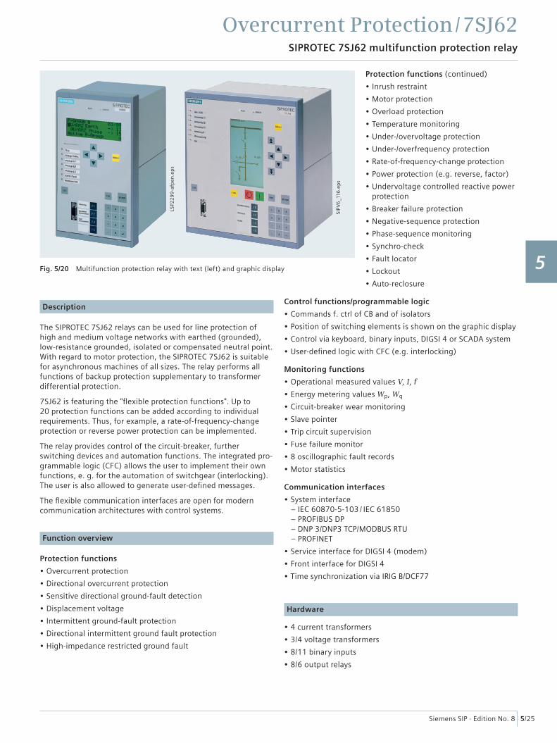
Fig. 5/20 Multifunction protection relay with text (left) and graphic display
SIPV
6_1
16.e
ps
Description
The SIPROTEC 7SJ62 relays can be used for line protection of high and medium voltage networks with earthed (grounded), low-resistance grounded, isolated or compensated neutral point. With regard to motor protection, the SIPROTEC 7SJ62 is suitable for asynchronous machines of all sizes. The relay performs all functions of backup protection supplementary to transformer differential protection.
7SJ62 is featuring the "fl exible protection functions". Up to 20 protection functions can be added according to individual requirements. Thus, for example, a rate-of-frequency-change protection or reverse power protection can be implemented.
The relay provides control of the circuit-breaker, further switching devices and automation functions. The integrated pro-grammable logic (CFC) allows the user to implement their own functions, e. g. for the automation of switchgear (interlocking). The user is also allowed to generate user-defi ned messages.
The fl exible communication interfaces are open for modern communication architectures with control systems.
Function overview
Protection functions
• Overcurrent protection
• Directional overcurrent protection
• Sensitive directional ground-fault detection
• Displacement voltage
• Intermittent ground-fault protection
• Directional intermittent ground fault protection
• High-impedance restricted ground fault
LSP2
29
9-a
fpen
.ep
s
1
2
3
4
5
6
7
8
9
10
11
12
13
14
15
Overcurrent Protection / 7SJ62Application
5/26 Siemens SIP · Edition No. 8
LSA2958-egpen.eps
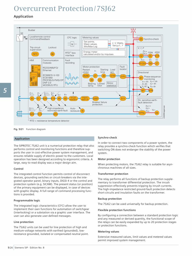
Fig. 5/21 Function diagram
Application
The SIPROTEC 7SJ62 unit is a numerical protection relay that also performs control and monitoring functions and therefore sup-ports the user in cost-effective power system management, and ensures reliable supply of electric power to the customers. Local operation has been designed according to ergonomic criteria. A large, easy-to-read display was a major design aim.
Control
The integrated control function permits control of disconnect devices, grounding switches or circuit-breakers via the inte-grated operator panel, binary inputs, DIGSI 4 or the control and protection system (e.g. SICAM). The present status (or position) of the primary equipment can be displayed, in case of devices with graphic display. A full range of command processing func-tions is provided.
Programmable logic
The integrated logic characteristics (CFC) allow the user to implement their own functions for automation of switchgear (interlocking) or a substation via a graphic user interface. The user can also generate user-defi ned messages.
Line protection
The 7SJ62 units can be used for line protection of high and medium-voltage networks with earthed (grounded), low-resistance grounded, isolated or compensated neutral point.
Synchro-check
In order to connect two components of a power system, the relay provides a synchro-check function which verifi es that switching ON does not endanger the stability of the power system.
Motor protection
When protecting motors, the 7SJ62 relay is suitable for asyn-chronous machines of all sizes.
Transformer protection
The relay performs all functions of backup protection supple-mentary to transformer differential protection. The inrush suppression effectively prevents tripping by inrush currents.The high-impedance restricted ground-fault protection detects short-circuits and insulation faults on the transformer.
Backup protection
The 7SJ62 can be used universally for backup protection.
Flexible protection functions
By confi guring a connection between a standard protection logic and any measured or derived quantity, the functional scope of the relays can be easily expanded by up to 20 protection stages or protection functions.
Metering values
Extensive measured values, limit values and metered values permit improved system management.
1
2
3
4
5
6
7
8
9
10
11
12
13
14
15
Overcurrent Protection / 7SJ62Application
5/27Siemens SIP · Edition No. 8
ANSI IEC Protection functions
50, 50N I>, I>>, I>>>, IE>, IE>>,IE>>> Defi nite-time overcurrent protection (phase/neutral)
50, 51V, 51N Ip, IEp Inverse overcurrent protection (phase/neutral), phase function with voltage-dependent option
67, 67N Idir>, Idir>>, Ip dirIEdir>, IEdir>>, IEp dir
Directional overcurrent protection (defi nite/inverse, phase/neutral),Directional comparison protection
67Ns/50Ns IEE>, IEE>>, IEEp Directional / non-directional sensitive ground-fault detection
– Cold load pick-up (dynamic setting change)
59N/64 VE, V0> Displacement voltage, zero-sequence voltage
– IIE> Intermittent ground fault
67Ns IIE dir> Directional intermittent ground fault protection
87N High-impedance restricted ground-fault protection
50BF Breaker failure protection
79 Auto-reclosure
25 Synchro-check
46 I2> Phase-balance current protection (negative-sequence protection)
47 V2>, phase-sequence Unbalance-voltage protection and / or phase-sequence monitoring
49 ϑ> Thermal overload protection
48 Starting time supervision
51M Load jam protection
14 Locked rotor protection
66/86 Restart inhibit
37 I< Undercurrent monitoring
38 Temperature monitoring via external device (RTD-box), e.g. bearing temperature monitoring
27, 59 V<, V> Undervoltage / overvoltage protection
59R dV/dt Rate-of-voltage-change protection
32 P<>, Q<> Reverse-power, forward-power protection
27/Q Q>/V< Undervoltage-controlled reactive power protection
55 cos φ Power factor protection
81O/U f>, f< Overfrequency / underfrequency protection
81R df/dt Rate-of-frequency-change protection
21FL Fault locator
1
2
3
4
5
6
7
8
9
10
11
12
13
14
15
Overcurrent Protection / 7SJ62Construction, protection functions
5/28 Siemens SIP · Edition No. 8
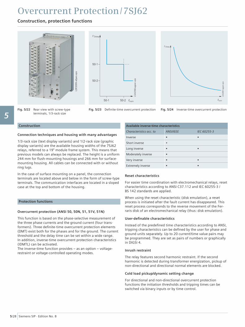
Fig. 5/22 Rear view with screw-type terminals, 1/3-rack size
Fig. 5/23 Defi nite-time overcurrent protection Fig. 5/24 Inverse-time overcurrent protection
LSP2
09
9-a
fpen
.ep
s
Construction
Connection techniques and housing with many advantages
1/3-rack size (text display variants) and 1/2-rack size (graphic display variants) are the available housing widths of the 7SJ62 relays, referred to a 19" module frame system. This means that previous models can always be replaced. The height is a uniform 244 mm for fl ush-mounting housings and 266 mm for surface-mounting housing. All cables can be connected with or without ring lugs.
In the case of surface mounting on a panel, the connection terminals are located above and below in the form of screw-type terminals. The communication interfaces are located in a sloped case at the top and bottom of the housing.
Protection functions
Overcurrent protection (ANSI 50, 50N, 51, 51V, 51N)
This function is based on the phase-selective measurement of the three phase currents and the ground current (four trans- formers). Three defi nite-time overcurrent protection elements (DMT) exist both for the phases and for the ground. The current threshold and the delay time can be set within a wide range. In addition, inverse-time overcurrent protection characteristics (IDMTL) can be activated. The inverse-time function provides – as an option – voltage-restraint or voltage-controlled operating modes.
Available inverse-time characteristics
Characteristics acc. to ANSI/IEEE IEC 60255-3
Inverse • •
Short inverse •
Long inverse • •
Moderately inverse •
Very inverse • •
Extremely inverse • •
Reset characteristics
For easier time coordination with electromechanical relays, reset characteristics according to ANSI C37.112 and IEC 60255-3 /BS 142 standards are applied.
When using the reset characteristic (disk emulation), a reset process is initiated after the fault current has disappeared. This reset process corresponds to the reverse movement of the Fer-raris disk of an electromechanical relay (thus: disk emulation).
User-defi nable characteristics
Instead of the predefi ned time characteristics according to ANSI, tripping characteristics can be defi ned by the user for phase and ground units separately. Up to 20 current/time value pairs may be programmed. They are set as pairs of numbers or graphically in DIGSI 4.
Inrush restraint
The relay features second harmonic restraint. If the second harmonic is detected during transformer energization, pickup of non-directional and directional normal elements are blocked.
Cold load pickup/dynamic setting change
For directional and non-directional overcurrent protection functions the initiation thresholds and tripping times can be switched via binary inputs or by time control.
1
2
3
4
5
6
7
8
9
10
11
12
13
14
15
Overcurrent Protection / 7SJ62Protection functions
5/29Siemens SIP · Edition No. 8
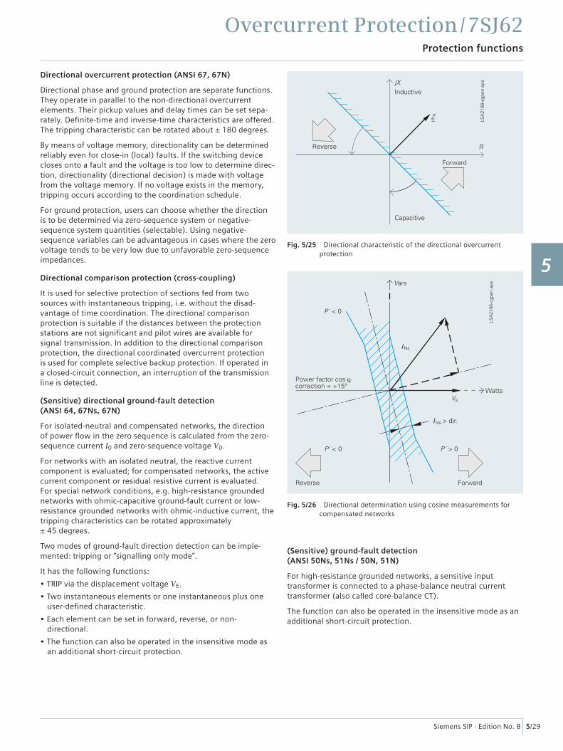
Fig. 5/25 Directional characteristic of the directional overcurrent protection
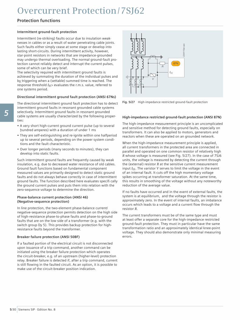
Fig. 5/26 Directional determination using cosine measurements for compensated networks
Directional overcurrent protection (ANSI 67, 67N)
Directional phase and ground protection are separate functions. They operate in parallel to the non-directional overcurrent elements. Their pickup values and delay times can be set sepa-rately. Defi nite-time and inverse-time characteristics are offered. The tripping characteristic can be rotated about ± 180 degrees.
By means of voltage memory, directionality can be determined reliably even for close-in (local) faults. If the switching device closes onto a fault and the voltage is too low to determine direc-tion, directionality (directional decision) is made with voltage from the voltage memory. If no voltage exists in the memory, tripping occurs according to the coordination schedule.
For ground protection, users can choose whether the direction is to be determined via zero-sequence system or negative-sequence system quantities (selectable). Using negative-sequence variables can be advantageous in cases where the zero voltage tends to be very low due to unfavorable zero-sequence impedances.
Directional comparison protection (cross-coupling)
It is used for selective protection of sections fed from two sources with instantaneous tripping, i.e. without the disad- vantage of time coordination. The directional comparison protection is suitable if the distances between the protection stations are not signifi cant and pilot wires are available for signal transmission. In addition to the directional comparison protection, the directional coordinated overcurrent protection is used for complete selective backup protection. If operated in a closed-circuit connection, an interruption of the transmission line is detected.
(Sensitive) directional ground-fault detection (ANSI 64, 67Ns, 67N)
For isolated-neutral and compensated networks, the direction of power fl ow in the zero sequence is calculated from the zero-sequence current I0 and zero-sequence voltage V0.
For networks with an isolated neutral, the reactive current component is evaluated; for compensated networks, the active current component or residual resistive current is evaluated. For special network conditions, e.g. high-resistance grounded networks with ohmic-capacitive ground-fault current or low-resistance grounded networks with ohmic-inductive current, the tripping characteristics can be rotated approximately ± 45 degrees.
Two modes of ground-fault direction detection can be imple-mented: tripping or “signalling only mode”.
It has the following functions:
• TRIP via the displacement voltage VE.
• Two instantaneous elements or one instantaneous plus one user-defi ned characteristic.
• Each element can be set in forward, reverse, or non-directional.
• The function can also be operated in the insensitive mode as an additional short-circuit protection.
(Sensitive) ground-fault detection (ANSI 50Ns, 51Ns / 50N, 51N)
For high-resistance grounded networks, a sensitive input transformer is connected to a phase-balance neutral current transformer (also called core-balance CT).
The function can also be operated in the insensitive mode as an additional short-circuit protection.
1
2
3
4
5
6
7
8
9
10
11
12
13
14
15
Overcurrent Protection / 7SJ62Protection functions
5/30 Siemens SIP · Edition No. 8
Intermittent ground-fault protection
Intermittent (re-striking) faults occur due to insulation weak-nesses in cables or as a result of water penetrating cable joints. Such faults either simply cease at some stage or develop into lasting short-circuits. During intermittent activity, however, star-point resistors in networks that are impedance-grounded may undergo thermal overloading. The normal ground-fault pro-tection cannot reliably detect and interrupt the current pulses, some of which can be very brief.The selectivity required with intermittent ground faults is achieved by summating the duration of the individual pulses and by triggering when a (settable) summed time is reached. The response threshold IIE> evaluates the r.m.s. value, referred to one systems period.
Directional intermittent ground fault protection (ANSI 67Ns)
The directional intermittent ground fault protection has to detect intermittent ground faults in resonant grounded cable systems selectively. Intermittent ground faults in resonant grounded cable systems are usually characterized by the following proper-ties:
• A very short high-current ground current pulse (up to several hundred amperes) with a duration of under 1 ms
• They are self-extinguishing and re-ignite within one halfperiod up to several periods, depending on the power system condi-tions and the fault characteristic.
• Over longer periods (many seconds to minutes), they can develop into static faults.
Such intermittent ground faults are frequently caused by weak insulation, e.g. due to decreased water resistance of old cables. Ground fault functions based on fundamental component measured values are primarily designed to detect static ground faults and do not always behave correctly in case of intermittent ground faults. The function described here evaluates specifi cally the ground current pulses and puts them into relation with the zero-sequence voltage to determine the direction.
Phase-balance current protection (ANSI 46)(Negative-sequence protection)
In line protection, the two-element phase-balance current/negative-sequence protection permits detection on the high side of high-resistance phase-to-phase faults and phase-to-ground faults that are on the low side of a transformer (e.g. with the switch group Dy 5). This provides backup protection for high-resistance faults beyond the transformer.
Breaker failure protection (ANSI 50BF)
If a faulted portion of the electrical circuit is not disconnected upon issuance of a trip command, another command can be initiated using the breaker failure protection which operates the circuit-breaker, e.g. of an upstream (higher-level) protection relay. Breaker failure is detected if, after a trip command, current is still fl owing in the faulted circuit. As an option, it is possible to make use of the circuit-breaker position indication.
High-impedance restricted ground-fault protection (ANSI 87N)
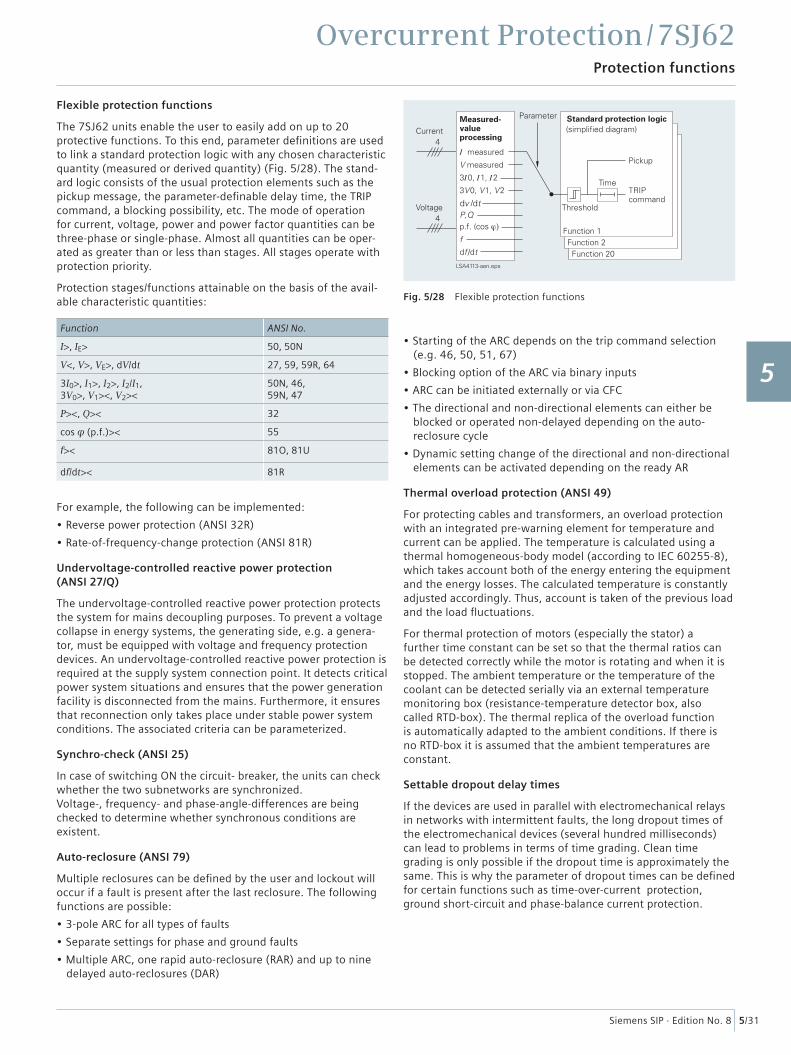
The high-impedance measurement principle is an uncomplicated and sensitive method for detecting ground faults, especially on transformers. It can also be applied to motors, generators and reactors when these are operated on an grounded network.
When the high-impedance measurement principle is applied, all current transformers in the protected area are connected in parallel and operated on one common resistor of relatively high R whose voltage is measured (see Fig. 5/27). In the case of 7SJ6 units, the voltage is measured by detecting the current through the (external) resistor R at the sensitive current measurement input IEE. The varistor V serves to limit the voltage in the event of an internal fault. It cuts off the high momentary voltage spikes occurring at transformer saturation. At the same time, this results in smoothing of the voltage without any noteworthy reduction of the average value.
If no faults have occurred and in the event of external faults, the system is at equilibrium, and the voltage through the resistor is approximately zero. In the event of internal faults, an imbalance occurs which leads to a voltage and a current fl ow through the resistor R.
The current transformers must be of the same type and must at least offer a separate core for the high-impedance restricted ground-fault protection. They must in particular have the same transformation ratio and an approximately identical knee-point voltage. They should also demonstrate only minimal measuring errors.
Fig. 5/27 High-impedance restricted ground-fault protection
1
2
3
4
5
6
7
8
9
10
11
12
13
14
15
Overcurrent Protection / 7SJ62Protection functions
5/31Siemens SIP · Edition No. 8
���������� �
������
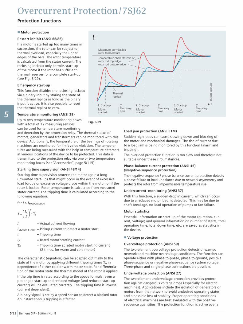
Fig. 5/28 Flexible protection functions
Flexible protection functions
The 7SJ62 units enable the user to easily add on up to 20 protective functions. To this end, parameter defi nitions are used to link a standard protection logic with any chosen characteristic quantity (measured or derived quantity) (Fig. 5/28). The stand- ard logic consists of the usual protection elements such as the pickup message, the parameter-defi nable delay time, the TRIP command, a blocking possibility, etc. The mode of operation for current, voltage, power and power factor quantities can be three-phase or single-phase. Almost all quantities can be oper-ated as greater than or less than stages. All stages operate with protection priority.
Protection stages/functions attainable on the basis of the avail-able characteristic quantities:
Function ANSI No.
I>, IE> 50, 50N
V<, V>, VE>, dV/dt 27, 59, 59R, 64
3I0>, I1>, I2>, I2/I1, 3V0>, V1><, V2><
50N, 46, 59N, 47
P><, Q>< 32
cos φ (p.f.)>< 55
f>< 81O, 81U
df/dt>< 81R
For example, the following can be implemented:
• Reverse power protection (ANSI 32R)
• Rate-of-frequency-change protection (ANSI 81R)
Undervoltage-controlled reactive power protection (ANSI 27/Q)
The undervoltage-controlled reactive power protection protects the system for mains decoupling purposes. To prevent a voltage collapse in energy systems, the generating side, e.g. a genera-tor, must be equipped with voltage and frequency protection devices. An undervoltage-controlled reactive power protection is required at the supply system connection point. It detects critical power system situations and ensures that the power generation facility is disconnected from the mains. Furthermore, it ensures that reconnection only takes place under stable power system conditions. The associated criteria can be parameterized.
Synchro-check (ANSI 25)
In case of switching ON the circuit- breaker, the units can check whether the two subnetworks are synchronized. Voltage-, frequency- and phase-angle-differences are being checked to determine whether synchronous conditions are existent.
Auto-reclosure (ANSI 79)
Multiple reclosures can be defi ned by the user and lockout will occur if a fault is present after the last reclosure. The following functions are possible:
• 3-pole ARC for all types of faults
• Separate settings for phase and ground faults
• Multiple ARC, one rapid auto-reclosure (RAR) and up to nine delayed auto-reclosures (DAR)
• Starting of the ARC depends on the trip command selection (e.g. 46, 50, 51, 67)
• Blocking option of the ARC via binary inputs
• ARC can be initiated externally or via CFC
• The directional and non-directional elements can either be blocked or operated non-delayed depending on the auto- reclosure cycle
• Dynamic setting change of the directional and non-directional elements can be activated depending on the ready AR
Thermal overload protection (ANSI 49)
For protecting cables and transformers, an overload protection with an integrated pre-warning element for temperature and current can be applied. The temperature is calculated using a thermal homogeneous-body model (according to IEC 60255-8), which takes account both of the energy entering the equipment and the energy losses. The calculated temperature is constantly adjusted accordingly. Thus, account is taken of the previous load and the load fl uctuations.
For thermal protection of motors (especially the stator) a further time constant can be set so that the thermal ratios can be detected correctly while the motor is rotating and when it is stopped. The ambient temperature or the temperature of the coolant can be detected serially via an external temperature monitoring box (resistance-temperature detector box, also called RTD-box). The thermal replica of the overload function is automatically adapted to the ambient conditions. If there is no RTD-box it is assumed that the ambient temperatures are constant.
Settable dropout delay times
If the devices are used in parallel with electromechanical relays in networks with intermittent faults, the long dropout times of the electromechanical devices (several hundred milliseconds) can lead to problems in terms of time grading. Clean time grading is only possible if the dropout time is approximately the same. This is why the parameter of dropout times can be defi ned for certain functions such as time-over-current protection, ground short-circuit and phase-balance current protection.
1
2
3
4
5
6
7
8
9
10
11
12
13
14
15
Overcurrent Protection / 7SJ62Protection functions
5/32 Siemens SIP · Edition No. 8
Fig. 5/29
Motor protection
Restart inhibit (ANSI 66/86)
If a motor is started up too many times in succession, the rotor can be subject to thermal overload, especially the upper edges of the bars. The rotor temperature is calculated from the stator current. The reclosing lockout only permits start-up of the motor if the rotor has suffi cient thermal reserves for a complete start-up (see Fig. 5/29).
Emergency start-up
This function disables the reclosing lockout via a binary input by storing the state of the thermal replica as long as the binary input is active. It is also possible to reset the thermal replica to zero.
Temperature monitoring (ANSI 38)
Up to two temperature monitoring boxes with a total of 12 measuring sensors can be used for temperature monitoring and detection by the protection relay. The thermal status of motors, generators and transformers can be monitored with this device. Additionally, the temperature of the bearings of rotating machines are monitored for limit value violation. The tempera-tures are being measured with the help of temperature detectors at various locations of the device to be protected. This data is transmitted to the protection relay via one or two temperature monitoring boxes (see “Accessories”, page 5/115).
Starting time supervision (ANSI 48/14)
Starting time supervision protects the motor against long unwanted start-ups that might occur in the event of excessive load torque or excessive voltage drops within the motor, or if the rotor is locked. Rotor temperature is calculated from measured stator current. The tripping time is calculated according to the following equation:
for I > IMOTOR START
t =
IA
I
⎛
⎝ ⎜
⎞
⎠ ⎟
2
⋅ TA
I = Actual current fl owing
IMOTOR START = Pickup current to detect a motor start
t = Tripping time
IA = Rated motor starting current
TA = Tripping time at rated motor starting current (2 times, for warm and cold motor)
The characteristic (equation) can be adapted optimally to the state of the motor by applying different tripping times TA in dependence of either cold or warm motor state. For differentia-tion of the motor state the thermal model of the rotor is applied.
If the trip time is rated according to the above formula, even a prolonged start-up and reduced voltage (and reduced start-up current) will be evaluated correctly. The tripping time is inverse (current dependent).
A binary signal is set by a speed sensor to detect a blocked rotor. An instantaneous tripping is effected.
Load jam protection (ANSI 51M)
Sudden high loads can cause slowing down and blocking of the motor and mechanical damages. The rise of current due to a load jam is being monitored by this function (alarm and tripping).
The overload protection function is too slow and therefore not suitable under these circumstances.
Phase-balance current protection (ANSI 46)(Negative-sequence protection)
The negative-sequence / phase-balance current protection detects a phase failure or load unbalance due to network asymmetry and protects the rotor from impermissible temperature rise.
Undercurrent monitoring (ANSI 37)
With this function, a sudden drop in current, which can occur due to a reduced motor load, is detected. This may be due to shaft breakage, no-load operation of pumps or fan failure.
Motor statistics
Essential information on start-up of the motor (duration, cur-rent, voltage) and general information on number of starts, total operating time, total down time, etc. are saved as statistics in the device.
Voltage protection
Overvoltage protection (ANSI 59)
The two-element overvoltage protection detects unwanted network and machine overvoltage conditions. The function can operate either with phase-to-phase, phase-to-ground, positive phase-sequence or negative phase-sequence system voltage. Three-phase and single-phase connections are possible.
Undervoltage protection (ANSI 27)
The two-element undervoltage protection provides protec-tion against dangerous voltage drops (especially for electric machines). Applications include the isolation of generators or motors from the network to avoid undesired operating states and a possible loss of stability. Proper operating conditions of electrical machines are best evaluated with the positive-sequence quantities. The protection function is active over a
1
2
3
4
5
6
7
8
9
10
11
12
13
14
15
Overcurrent Protection / 7SJ62Protection functions
5/33Siemens SIP · Edition No. 8
wide frequency range (45 to 55, 55 to 65 Hz)1). Even when falling below this frequency range the function continues to work, however, with a greater tolerance band.
The function can operate either with phase-to-phase, phase-to-ground or positive phase-sequence voltage and can be moni-tored with a current criterion. Three-phase and single-phase connections are possible.
Frequency protection (ANSI 81O/U)
Frequency protection can be used for over- frequency and under-frequency protection. Electric machines and parts of the system are protected from unwanted speed deviations. Unwanted frequency changes in the network can be detected and the load can be removed at a specifi ed frequency setting.
Frequency protection can be used over a wide frequency range (40 to 60, 50 to 70 Hz)1). There are four elements (select- able as overfrequency or underfrequency) and each element can be delayed separately. Blocking of the frequency protection can be performed if using a binary input or by using an undervoltage element.
Fault locator (ANSI 21FL)
The integrated fault locator calculates the fault impedance and the distance-to-fault. The results are displayed in Ω, kilometers (miles) and in percent of the line length.
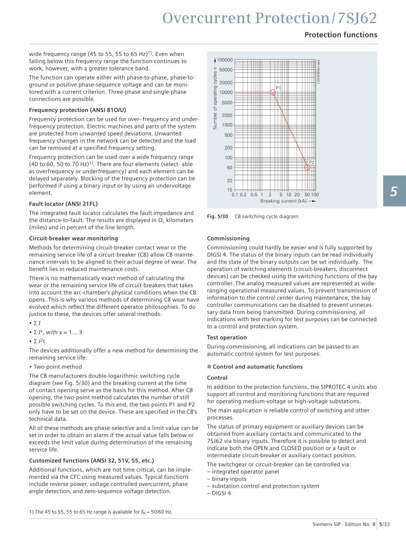
Circuit-breaker wear monitoring
Methods for determining circuit-breaker contact wear or the remaining service life of a circuit-breaker (CB) allow CB mainte-nance intervals to be aligned to their actual degree of wear. The benefi t lies in reduced maintenance costs.
There is no mathematically exact method of calculating the wear or the remaining service life of circuit-breakers that takes into account the arc-chamber's physical conditions when the CB opens. This is why various methods of determining CB wear have evolved which refl ect the different operator philosophies. To do justice to these, the devices offer several methods:
• Σ I
• Σ Ix, with x = 1... 3
• Σ i2t
The devices additionally offer a new method for determining the remaining service life:
• Two-point method
The CB manufacturers double-logarithmic switching cycle diagram (see Fig. 5/30) and the breaking current at the time of contact opening serve as the basis for this method. After CB opening, the two-point method calculates the number of still possible switching cycles. To this end, the two points P1 and P2 only have to be set on the device. These are specifi ed in the CB's technical data.
All of these methods are phase-selective and a limit value can be set in order to obtain an alarm if the actual value falls below or exceeds the limit value during determination of the remaining service life.
Customized functions (ANSI 32, 51V, 55, etc.)
Additional functions, which are not time critical, can be imple-mented via the CFC using measured values. Typical functions include reverse power, voltage controlled overcurrent, phase angle detection, and zero-sequence voltage detection.
Commissioning
Commissioning could hardly be easier and is fully supported by DIGSI 4. The status of the binary inputs can be read individually and the state of the binary outputs can be set individually. The operation of switching elements (circuit-breakers, disconnect devices) can be checked using the switching functions of the bay controller. The analog measured values are represented as wide-ranging operational measured values. To prevent transmission of information to the control center during maintenance, the bay controller communications can be disabled to prevent unneces-sary data from being transmitted. During commissioning, all indications with test marking for test purposes can be connected to a control and protection system.
Test operation
During commissioning, all indications can be passed to an automatic control system for test purposes.
Control and automatic functions
Control
In addition to the protection functions, the SIPROTEC 4 units also support all control and monitoring functions that are required for operating medium-voltage or high-voltage substations.
The main application is reliable control of switching and other processes.
The status of primary equipment or auxiliary devices can be obtained from auxiliary contacts and communicated to the 7SJ62 via binary inputs. Therefore it is possible to detect and indicate both the OPEN and CLOSED position or a fault or intermediate circuit-breaker or auxiliary contact position.
The switchgear or circuit-breaker can be controlled via: – integrated operator panel – binary inputs– substation control and protection system– DIGSI 4
Fig. 5/30 CB switching cycle diagram
1) The 45 to 55, 55 to 65 Hz range is available for fN = 50/60 Hz.
1
2
3
4
5
6
7
8
9
10
11
12
13
14
15
Overcurrent Protection / 7SJ62Functions
5/34 Siemens SIP · Edition No. 8
Automation / user-defi ned logic
With integrated logic, the user can set, via a graphic interface (CFC), specifi c functions for the automation of switchgear or substation. Functions are activated via function keys, binary input or via communication interface.
Switching authority
Switching authority is determined according to parameters and communication.
If a source is set to “LOCAL”, only local switching operations are possible. The following sequence of switching authority is laid down: “LOCAL”; DIGSI PC program, “REMOTE”.
Command processing
All the functionality of command processing is offered. This includes the processing of single and double commands with or without feedback, sophisticated monitoring of the control hardware and software, checking of the external process, control actions using functions such as runtime monitoring and automatic command termination after output. Here are some typical applications:
• Single and double commands using 1, 1 plus 1 common or 2 trip contacts
• User-defi nable bay interlocks
• Operating sequences combining several switching operations such as control of circuit-breakers, disconnectors and ground-ing switches
• Triggering of switching operations, indications or alarm by combination with existing information
Assignment of feedback to command
The positions of the circuit-breaker or switching devices and transformer taps are acquired by feedback. These indication inputs are logically assigned to the corresponding command outputs. The unit can therefore distinguish whether the indica-tion change is a consequence of switching operation or whether it is a spontaneous change of state.
Chatter disable
Chatter disable feature evaluates whether, in a confi gured period of time, the number of status changes of indication input exceeds a specifi ed fi gure. If exceeded, the indication input is blocked for a certain period, so that the event list will not record excessive operations.
Indication fi ltering and delay
Binary indications can be fi ltered or delayed.
Filtering serves to suppress brief changes in potential at the indication input. The indication is passed on only if the indica-tion voltage is still present after a set period of time. In the event of indication delay, there is a wait for a preset time. The information is passed on only if the indication voltage is still present after this time.
Indication derivation
A further indication (or a command) can be derived from an existing indication. Group indications can also be formed. The volume of information to the system interface can thus be reduced and restricted to the most important signals.
Switchgear cubicles for high/medium voltage
All units are designed specifi cally to meet the requirements of high/medium-voltage applications.
In general, no separate measuring instruments (e.g., for current, voltage, frequency, …) or additional control components are necessary.
Measured values
The r.m.s. values are calculated from the acquired current and voltage along with the power factor, frequency, active and reac-tive power. The following functions are available for measured value processing:
• Currents IL1, IL2, IL3, IE, IEE (67Ns)
• Voltages VL1, VL2, VL3, VL1L2, VL2L3, VL3L1
• Symmetrical components I1, I2, 3I0; V1, V2, V0
• Power Watts, Vars, VA/P, Q, S (P, Q: total and phase selective)
• Power factor (cos φ), (total and phase selective)
• Frequency
• Energy ± kWh, ± kVarh, forward and reverse power fl ow
• Mean as well as minimum and maximum current and voltage values
• Operating hours counter
• Mean operating temperature of overload function
• Limit value monitoringLimit values are monitored using programmable logic in the CFC. Commands can be derived from this limit value indica-tion.
• Zero suppressionIn a certain range of very low measured values, the value is set to zero to suppress interference.
Fig. 5/31 NXAIR panel (air-insulated)
LSP2
07
7f.
eps
1
2
3
4
5
6
7
8
9
10
11
12
13
14
15
Overcurrent Protection / 7SJ62Communication
5/35Siemens SIP · Edition No. 8
Communication
In terms of communication, the units offer substantial fl exibility in the context of connection to industrial and power automation standards. Communication can be extended or added on thanks to modules for retrofi tting on which the common protocols run. Therefore, also in the future it will be possible to optimally inte-grate units into the changing communication infrastructure, for example in Ethernet networks (which will also be used increasingly in the power supply sector in the years to come).
Serial front interface
There is a serial RS232 interface on the front of all the units. All of the unit’s functions can be set on a PC by means of the DIGSI 4 protection operation program. Commissioning tools and fault analysis are also built into the program and are available through this interface.
Rear-mounted interfaces1)
A number of communication modules suitable for various applica-tions can be fi tted in the rear of the fl ush-mounting housing. In the fl ush-mounting housing, the modules can be easily replaced by the user. The interface modules support the following applica-tions:
• Time synchronization interfaceAll units feature a permanently integrated electrical time synchronization interface. It can be used to feed timing telegrams in IRIG-B or DCF77 format into the units via time synchronization receivers.
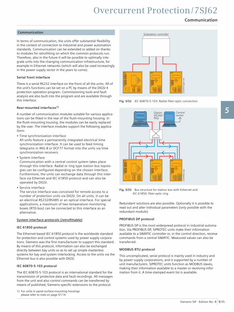
• System interface Communication with a central control system takes place through this interface. Radial or ring type station bus topolo-gies can be confi gured depending on the chosen interface. Furthermore, the units can exchange data through this inter-face via Ethernet and IEC 61850 protocol and can also be operated by DIGSI.
• Service interface The service interface was conceived for remote access to a number of protection units via DIGSI. On all units, it can be an electrical RS232/RS485 or an optical interface. For special applications, a maximum of two temperature monitoring boxes (RTD-box) can be connected to this interface as an alternative.
System interface protocols (retrofi ttable)
IEC 61850 protocol
The Ethernet-based IEC 61850 protocol is the worldwide standard for protection and control systems used by power supply corpora-tions. Siemens was the fi rst manufacturer to support this standard. By means of this protocol, information can also be exchanged directly between bay units so as to set up simple masterless systems for bay and system interlocking. Access to the units via the Ethernet bus is also possible with DIGSI.
IEC 60870-5-103 protocol
The IEC 60870-5-103 protocol is an international standard for the transmission of protective data and fault recordings. All messages from the unit and also control commands can be transferred by means of published, Siemens-specifi c extensions to the protocol.
Redundant solutions are also possible. Optionally it is possible to read out and alter individual parameters (only possible with the redundant module).
PROFIBUS DP protocol
PROFIBUS DP is the most widespread protocol in industrial automa-tion. Via PROFIBUS DP, SIPROTEC units make their information available to a SIMATIC controller or, in the control direction, receive commands from a central SIMATIC. Measured values can also be transferred.
MODBUS RTU protocol
This uncomplicated, serial protocol is mainly used in industry and by power supply corporations, and is supported by a number of unit manufacturers. SIPROTEC units function as MODBUS slaves, making their information available to a master or receiving infor-mation from it. A time-stamped event list is available.
Fig. 5/32 IEC 60870-5-103: Radial fi ber-optic connection
Fig. 5/33 Bus structure for station bus with Ethernet andIEC 61850, fi ber-optic ring
1) For units in panel surface-mounting housings please refer to note on page 5/114.
1
2
3
4
5
6
7
8
9
10
11
12
13
14
15
Overcurrent Protection / 7SJ62Communication
5/36 Siemens SIP · Edition No. 8
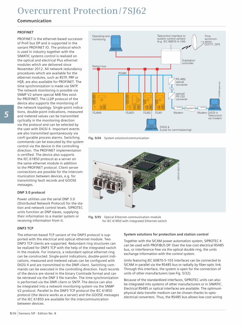
PROFINET
PROFINET is the ethernet-based successor of Profi bus DP and is supported in the variant PROFINET IO. The protocol which is used in industry together with the SIMATIC systems control is realized on the optical and electrical Plus ethernet modules which are delivered since November 2012. All network redundancy procedures which are available for the ethernet modules, such as RSTP, PRP or HSR, are also available for PROFINET. The time synchronization is made via SNTP. The network monitoring is possible via SNMP V2 where special MIB fi les exist for PROFINET. The LLDP protocol of the device also supports the monitoring of the network topology. Single-point indica-tions, double-point indications, measured and metered values can be transmitted cyclically in the monitoring direction via the protocol and can be selected by the user with DIGSI 4. Important events are also transmitted spontaneously via confi gurable process alarms. Switching commands can be executed by the system control via the device in the controlling direction. The PROFINET implementation is certifi ed. The device also supports the IEC 61850 protocol as a server on the same ethernet module in addition to the PROFINET protocol. Client server connections are possible for the intercom-munication between devices, e.g. for transmitting fault records and GOOSE messages.
DNP 3.0 protocol
Power utilities use the serial DNP 3.0 (Distributed Network Protocol) for the sta-tion and network control levels. SIPROTEC units function as DNP slaves, supplying their information to a master system or receiving information from it.
DNP3 TCP
The ethernet-based TCP variant of the DNP3 protocol is sup-ported with the electrical and optical ethernet module. Two DNP3 TCP clients are supported. Redundant ring structures can be realized for DNP3 TCP with the help of the integrated switch in the module. For instance, a redundant optical ethernet ring can be constructed. Single-point indications, double-point indi-cations, measured and metered values can be confi gured with DIGSI 4 and are transmitted to the DNPi client. Switching com-mands can be executed in the controlling direction. Fault records of the device are stored in the binary Comtrade format and can be retrieved via the DNP 3 fi le transfer. The time synchronization is performed via the DNPi client or SNTP. The device can also be integrated into a network monitoring system via the SNMP V2 protocol. Parallel to the DNP3 TCP protocol the IEC 61850 protocol (the device works as a server) and the GOOSE messages of the IEC 61850 are available for the intercommunication between devices.
System solutions for protection and station control
Together with the SICAM power automation system, SIPROTEC 4 can be used with PROFIBUS DP. Over the low-cost electrical RS485 bus, or interference-free via the optical double ring, the units exchange information with the control system.
Units featuring IEC 60870-5-103 interfaces can be connected to SICAM in parallel via the RS485 bus or radially by fi ber-optic link. Through this interface, the system is open for the connection of units of other manufacturers (see Fig. 5/32).
Because of the standardized interfaces, SIPROTEC units can also be integrated into systems of other manufacturers or in SIMATIC. Electrical RS485 or optical interfaces are available. The optimum physical data transfer medium can be chosen thanks to opto-electrical converters. Thus, the RS485 bus allows low-cost wiring
Fig. 5/34 System solution/communication
Fig. 5/35 Optical Ethernet communication modulefor IEC 61850 with integrated Ethernet-switch
LSP3
.01-
00
21.t
if
1
2
3
4
5
6
7
8
9
10
11
12
13
14
15
Overcurrent Protection / 7SJ62Typical connections
5/37Siemens SIP · Edition No. 8
in the cubicles and an interference-free optical connection to the master can be established.
For IEC 61850, an interoperable system solution is offered with SICAM PAS. Via the 100 Mbits/s Ethernet bus, the units are linked with PAS electrically or optically to the station PC. The interface is standardized, thus also enabling direct connection of units of other manufacturers to the Ethernet bus. With IEC 61850, how-ever, the units can also be used in other manufacturers’ systems (see Fig. 5/33).
Typical connections
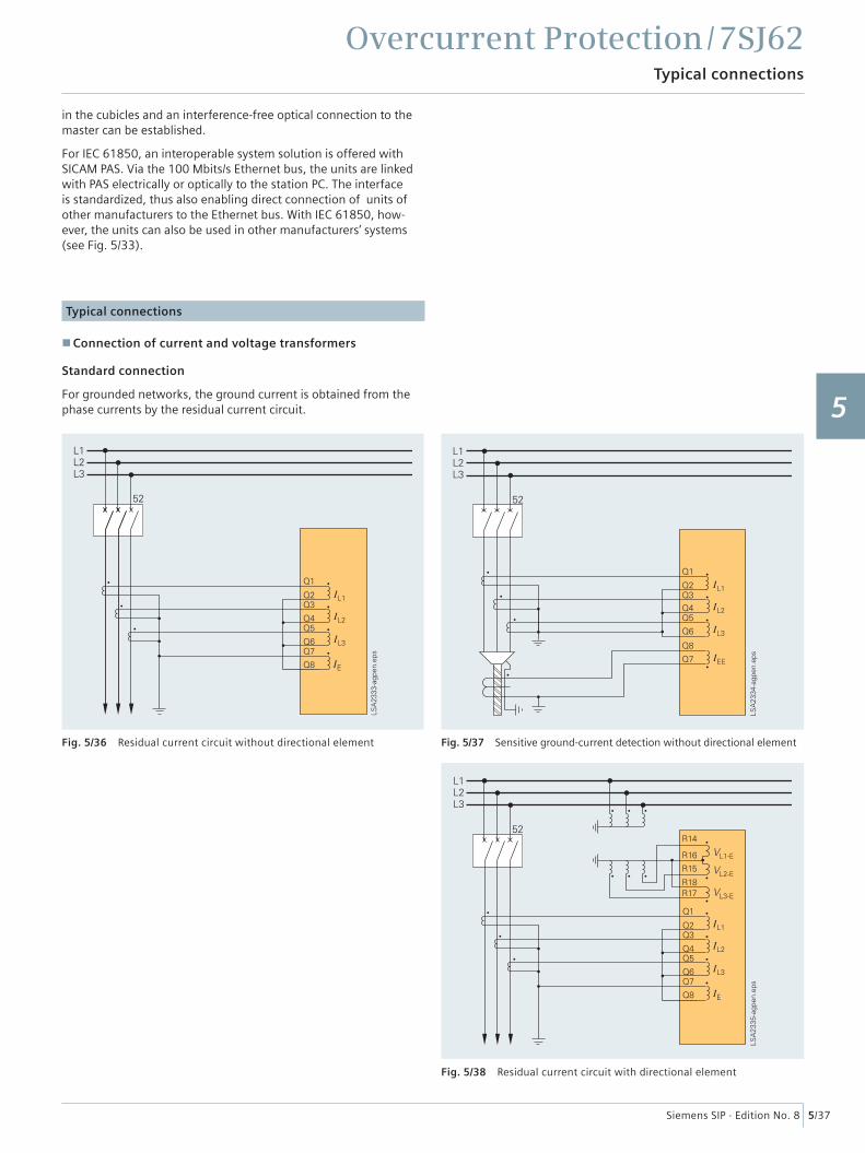
Connection of current and voltage transformers
Standard connection
For grounded networks, the ground current is obtained from the phase currents by the residual current circuit.
Fig. 5/36 Residual current circuit without directional element Fig. 5/37 Sensitive ground-current detection without directional element
Fig. 5/38 Residual current circuit with directional element
1
2
3
4
5
6
7
8
9
10
11
12
13
14
15
Overcurrent Protection / 7SJ62Typical connections
5/38 Siemens SIP · Edition No. 8
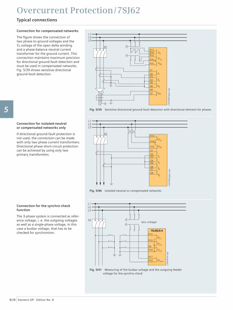
Connection for compensated networks
The fi gure shows the connection of two phase-to-ground voltages and the VE voltage of the open delta winding and a phase-balance neutral current transformer for the ground current. This connection maintains maximum precision for directional ground-fault detection and must be used in compensated networks.Fig. 5/39 shows sensitive directional ground-fault detection.
Connection for isolated-neutral or compensated networks only
If directional ground-fault protection is not used, the connection can be made with only two phase current transformers. Directional phase short-circuit protection can be achieved by using only two primary transformers.
Connection for the synchro-check function
The 3-phase system is connected as refer-ence voltage, i. e. the outgoing voltages as well as a single-phase voltage, in this case a busbar voltage, that has to be checked for synchronism.
Fig. 5/39 Sensitive directional ground-fault detection with directional element for phases
Fig. 5/40 Isolated-neutral or compensated networks
Fig. 5/41 Measuring of the busbar voltage and the outgoing feedervoltage for the synchro-check
1
2
3
4
5
6
7
8
9
10
11
12
13
14
15
Overcurrent Protection / 7SJ62Typical applications
5/39Siemens SIP · Edition No. 8
Typical applications
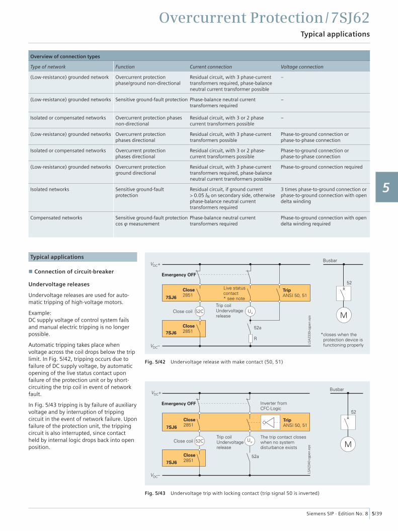
Connection of circuit-breaker
Undervoltage releases
Undervoltage releases are used for auto-matic tripping of high-voltage motors.
Example:DC supply voltage of control system fails and manual electric tripping is no longer possible.
Automatic tripping takes place when voltage across the coil drops below the trip limit. In Fig. 5/42, tripping occurs due to failure of DC supply voltage, by automatic opening of the live status contact upon failure of the protection unit or by short- circuiting the trip coil in event of network fault.
In Fig. 5/43 tripping is by failure of auxiliary voltage and by interruption of tripping circuit in the event of network failure. Upon failure of the protection unit, the tripping circuit is also interrupted, since contact held by internal logic drops back into open position.
Fig. 5/42 Undervoltage release with make contact (50, 51)
Fig. 5/43 Undervoltage trip with locking contact (trip signal 50 is inverted)
Overview of connection types
Type of network Function Current connection Voltage connection
(Low-resistance) grounded network Overcurrent protectionphase/ground non-directional
Residual circuit, with 3 phase-currenttransformers required, phase-balanceneutral current transformer possible
–
(Low-resistance) grounded networks Sensitive ground-fault protection Phase-balance neutral currenttransformers required
–
Isolated or compensated networks Overcurrent protection phases non-directional
Residual circuit, with 3 or 2 phasecurrent transformers possible
–
(Low-resistance) grounded networks Overcurrent protectionphases directional
Residual circuit, with 3 phase-currenttransformers possible
Phase-to-ground connection orphase-to-phase connection
Isolated or compensated networks Overcurrent protectionphases directional
Residual circuit, with 3 or 2 phase-current transformers possible
Phase-to-ground connection orphase-to-phase connection
(Low-resistance) grounded networks Overcurrent protectionground directional
Residual circuit, with 3 phase-currenttransformers required, phase-balanceneutral current transformers possible
Phase-to-ground connection required
Isolated networks Sensitive ground-faultprotection
Residual circuit, if ground current> 0.05 IN on secondary side, otherwisephase-balance neutral currenttransformers required
3 times phase-to-ground connection orphase-to-ground connection with opendelta winding
Compensated networks Sensitive ground-fault protection cos φ measurement
Phase-balance neutral currenttransformers required
Phase-to-ground connection with opendelta winding required
1
2
3
4
5
6
7
8
9
10
11
12
13
14
15
Overcurrent Protection / 7SJ62Typical applications
5/40 Siemens SIP · Edition No. 8
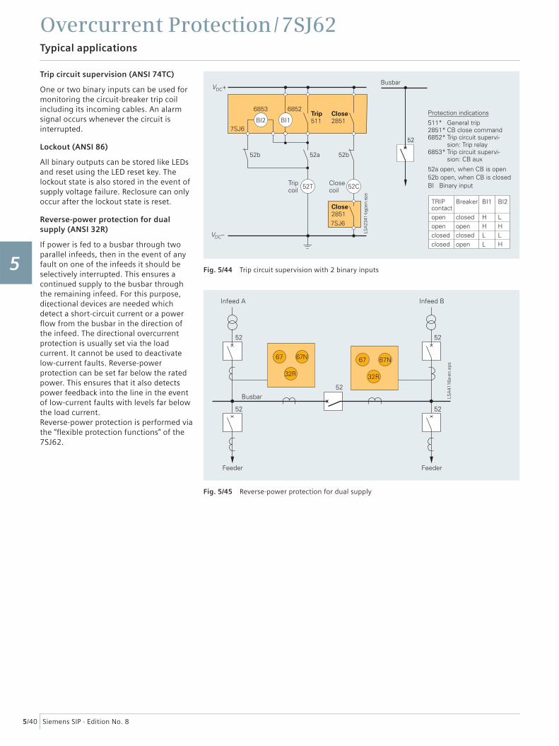
Trip circuit supervision (ANSI 74TC)
One or two binary inputs can be used for monitoring the circuit-breaker trip coil including its incoming cables. An alarm signal occurs whenever the circuit is interrupted.
Lockout (ANSI 86)
All binary outputs can be stored like LEDs and reset using the LED reset key. The lockout state is also stored in the event of supply voltage failure. Reclosure can only occur after the lockout state is reset.
Reverse-power protection for dual supply (ANSI 32R)
If power is fed to a busbar through two parallel infeeds, then in the event of any fault on one of the infeeds it should be selectively interrupted. This ensures a continued supply to the busbar through the remaining infeed. For this purpose, directional devices are needed which detect a short-circuit current or a power fl ow from the busbar in the direction of the infeed. The directional overcurrent protection is usually set via the load current. It cannot be used to deactivate low-current faults. Reverse-power protection can be set far below the rated power. This ensures that it also detects power feedback into the line in the event of low-current faults with levels far below the load current. Reverse-power protection is performed via the “fl exible protection functions” of the 7SJ62.
Fig. 5/44 Trip circuit supervision with 2 binary inputs
Fig. 5/45 Reverse-power protection for dual supply
1
2
3
4
5
6
7
8
9
10
11
12
13
14
15
Overcurrent Protection / 7SJ62Technical data
5/41Siemens SIP · Edition No. 8
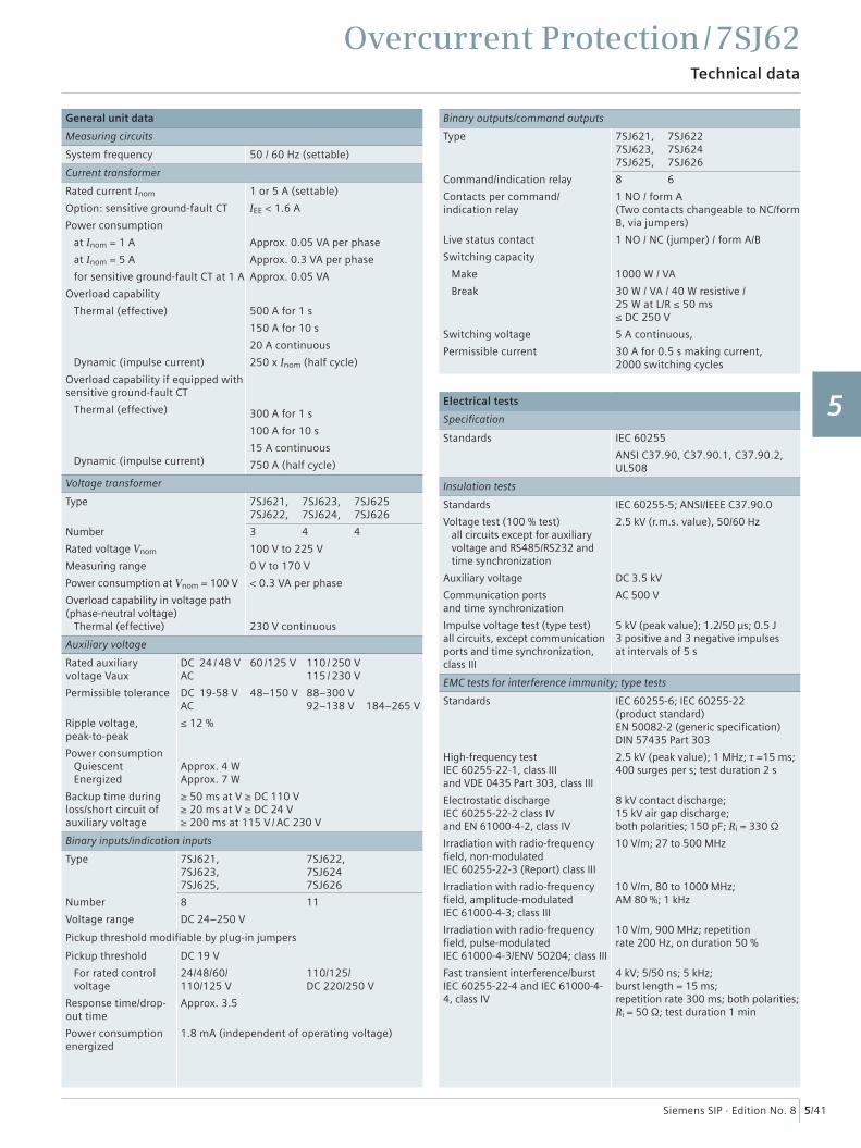
General unit data
Measuring circuits
System frequency 50 / 60 Hz (settable)
Current transformer
Rated current Inom
Option: sensitive ground-fault CT
Power consumption
at Inom = 1 A
at Inom = 5 A
for sensitive ground-fault CT at 1 A
Overload capability
Thermal (effective)
Dynamic (impulse current)
Overload capability if equipped with sensitive ground-fault CT
Thermal (effective)
Dynamic (impulse current)
1 or 5 A (settable)
IEE < 1.6 A
Approx. 0.05 VA per phase
Approx. 0.3 VA per phase
Approx. 0.05 VA
500 A for 1 s
150 A for 10 s
20 A continuous
250 x Inom (half cycle)
300 A for 1 s
100 A for 10 s
15 A continuous
750 A (half cycle)
Voltage transformer
Type
Number
Rated voltage Vnom
Measuring range
Power consumption at Vnom = 100 V
Overload capability in voltage path (phase-neutral voltage) Thermal (effective)
7SJ621, 7SJ623, 7SJ6257SJ622, 7SJ624, 7SJ626
3 4 4
100 V to 225 V
0 V to 170 V
< 0.3 VA per phase
230 V continuous
Auxiliary voltage
Rated auxiliary voltage Vaux
Permissible tolerance
Ripple voltage, peak-to-peak
Power consumption Quiescent Energized
Backup time during loss/short circuit of auxiliary voltage
DC 24 / 48 V 60 /125 V 110 / 250 VAC 115 / 230 V
DC 19-58 V 48–150 V 88–300 VAC 92–138 V 184–265 V
≤ 12 %
Approx. 4 WApprox. 7 W
≥ 50 ms at V ≥ DC 110 V≥ 20 ms at V ≥ DC 24 V≥ 200 ms at 115 V / AC 230 V
Binary inputs/indication inputs
Type
Number
Voltage range
7SJ621, 7SJ622,7SJ623, 7SJ624 7SJ625, 7SJ626
8 11
DC 24–250 V
Pickup threshold modifi able by plug-in jumpers
Pickup threshold
For rated control voltage
Response time/drop-out time
Power consumption energized
DC 19 V
24/48/60/ 110/125/110/125 V DC 220/250 V
Approx. 3.5
1.8 mA (independent of operating voltage)
Binary outputs/command outputs
Type
Command/indication relay
Contacts per command/indication relay
Live status contact
Switching capacity
Make
Break
Switching voltage
Permissible current
7SJ621, 7SJ6227SJ623, 7SJ6247SJ625, 7SJ626
8 6
1 NO / form A(Two contacts changeable to NC/form B, via jumpers)
1 NO / NC (jumper) / form A/B
1000 W / VA
30 W / VA / 40 W resistive / 25 W at L/R ≤ 50 ms≤ DC 250 V
5 A continuous,
30 A for 0.5 s making current, 2000 switching cycles
Electrical tests
Specifi cation
Standards IEC 60255
ANSI C37.90, C37.90.1, C37.90.2, UL508
Insulation tests
Standards
Voltage test (100 % test) all circuits except for auxiliary voltage and RS485/RS232 and time synchronization
Auxiliary voltage
Communication ports and time synchronization
Impulse voltage test (type test)all circuits, except communication ports and time synchronization, class III
IEC 60255-5; ANSI/IEEE C37.90.0
2.5 kV (r.m.s. value), 50/60 Hz
DC 3.5 kV
AC 500 V
5 kV (peak value); 1.2/50 µs; 0.5 J3 positive and 3 negative impulses at intervals of 5 s
EMC tests for interference immunity; type tests
Standards
High-frequency testIEC 60255-22-1, class IIIand VDE 0435 Part 303, class III
Electrostatic dischargeIEC 60255-22-2 class IVand EN 61000-4-2, class IV
Irradiation with radio-frequency fi eld, non-modulated IEC 60255-22-3 (Report) class III
Irradiation with radio-frequency fi eld, amplitude-modulated IEC 61000-4-3; class III
Irradiation with radio-frequency fi eld, pulse-modulated IEC 61000-4-3/ENV 50204; class III
Fast transient interference/burstIEC 60255-22-4 and IEC 61000-4-4, class IV
IEC 60255-6; IEC 60255-22 (product standard)EN 50082-2 (generic specifi cation)DIN 57435 Part 303
2.5 kV (peak value); 1 MHz; τ =15 ms;400 surges per s; test duration 2 s
8 kV contact discharge; 15 kV air gap discharge;both polarities; 150 pF; Ri = 330 Ω
10 V/m; 27 to 500 MHz
10 V/m, 80 to 1000 MHz; AM 80 %; 1 kHz
10 V/m, 900 MHz; repetition rate 200 Hz, on duration 50 %
4 kV; 5/50 ns; 5 kHz; burst length = 15 ms; repetition rate 300 ms; both polarities; Ri = 50 Ω; test duration 1 min
1
2
3
4
5
6
7
8
9
10
11
12
13
14
15
Overcurrent Protection / 7SJ62Technical data
5/42 Siemens SIP · Edition No. 8
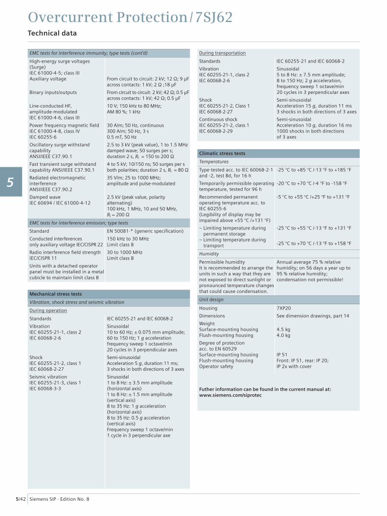
EMC tests for interference immunity; type tests (cont'd)
High-energy surge voltages (Surge)IEC 61000-4-5; class IIIAuxiliary voltage
Binary inputs/outputs
Line-conducted HF, amplitude-modulatedIEC 61000-4-6, class III
Power frequency magnetic fi eldIEC 61000-4-8, class IVIEC 60255-6
Oscillatory surge withstand capabilityANSI/IEEE C37.90.1
Fast transient surge withstand capability ANSI/IEEE C37.90.1
Radiated electromagnetic interferenceANSI/IEEE C37.90.2
Damped waveIEC 60694 / IEC 61000-4-12
From circuit to circuit: 2 kV; 12 Ω; 9 µFacross contacts: 1 kV; 2 Ω ;18 µF
From circuit to circuit: 2 kV; 42 Ω; 0.5 µFacross contacts: 1 kV; 42 Ω; 0.5 µF
10 V; 150 kHz to 80 MHz; AM 80 %; 1 kHz
30 A/m; 50 Hz, continuous300 A/m; 50 Hz, 3 s0.5 mT, 50 Hz
2.5 to 3 kV (peak value), 1 to 1.5 MHzdamped wave; 50 surges per s; duration 2 s, Ri = 150 to 200 Ω
4 to 5 kV; 10/150 ns; 50 surges per sboth polarities; duration 2 s, Ri = 80 Ω
35 V/m; 25 to 1000 MHz; amplitude and pulse-modulated
2.5 kV (peak value, polarity alternating)100 kHz, 1 MHz, 10 and 50 MHz, Ri = 200 Ω
EMC tests for interference emission; type tests
Standard
Conducted interferences only auxiliary voltage IEC/CISPR 22
Radio interference fi eld strength IEC/CISPR 11
Units with a detached operator panel must be installed in a metal cubicle to maintain limit class B
EN 50081-* (generic specifi cation)
150 kHz to 30 MHzLimit class B
30 to 1000 MHzLimit class B
Mechanical stress tests
Vibration, shock stress and seismic vibration
During operation
Standards
VibrationIEC 60255-21-1, class 2IEC 60068-2-6
ShockIEC 60255-21-2, class 1IEC 60068-2-27
Seismic vibrationIEC 60255-21-3, class 1IEC 60068-3-3
IEC 60255-21 and IEC 60068-2
Sinusoidal10 to 60 Hz; ± 0.075 mm amplitude;60 to 150 Hz; 1 g accelerationfrequency sweep 1 octave/min20 cycles in 3 perpendicular axes
Semi-sinusoidalAcceleration 5 g, duration 11 ms;3 shocks in both directions of 3 axes
Sinusoidal1 to 8 Hz: ± 3.5 mm amplitude (horizontal axis)1 to 8 Hz: ± 1.5 mm amplitude (vertical axis)8 to 35 Hz: 1 g acceleration (horizontal axis)8 to 35 Hz: 0.5 g acceleration (vertical axis) Frequency sweep 1 octave/min1 cycle in 3 perpendicular axe
During transportation
Standards
VibrationIEC 60255-21-1, class 2IEC 60068-2-6
ShockIEC 60255-21-2, Class 1IEC 60068-2-27
Continuous shockIEC 60255-21-2, class 1IEC 60068-2-29
IEC 60255-21 and IEC 60068-2
Sinusoidal5 to 8 Hz: ± 7.5 mm amplitude;8 to 150 Hz; 2 g acceleration,frequency sweep 1 octave/min20 cycles in 3 perpendicular axes
Semi-sinusoidalAcceleration 15 g, duration 11 ms3 shocks in both directions of 3 axes
Semi-sinusoidalAcceleration 10 g, duration 16 ms1000 shocks in both directions of 3 axes
Climatic stress tests
Temperatures
Type-tested acc. to IEC 60068-2-1 and -2, test Bd, for 16 h
Temporarily permissible operating temperature, tested for 96 h
Recommended permanent operating temperature acc. to IEC 60255-6(Legibility of display may be impaired above +55 °C /+131 °F)
– Limiting temperature during permanent storage
– Limiting temperature duringtransport
-25 °C to +85 °C /-13 °F to +185 °F
-20 °C to +70 °C /-4 °F to -158 °F
-5 °C to +55 °C /+25 °F to +131 °F
-25 °C to +55 °C /-13 °F to +131 °F
-25 °C to +70 °C /-13 °F to +158 °F
Humidity
Permissible humidityIt is recommended to arrange the units in such a way that they are not exposed to direct sunlight or pronounced temperature changes that could cause condensation.
Annual average 75 % relative humidity; on 56 days a year up to 95 % relative humidity; condensation not permissible!
Unit design
Housing
Dimensions
WeightSurface-mounting housingFlush-mounting housing
Degree of protection acc. to EN 60529Surface-mounting housingFlush-mounting housingOperator safety
7XP20
See dimension drawings, part 14
4.5 kg4.0 kg
IP 51Front: IP 51, rear: IP 20; IP 2x with cover
Futher information can be found in the current manual at:www.siemens.com/siprotec
1
2
3
4
5
6
7
8
9
10
11
12
13
14
15
Overcurrent Protection / 7SJ62Selection and ordering data
5/43Siemens SIP · Edition No. 8
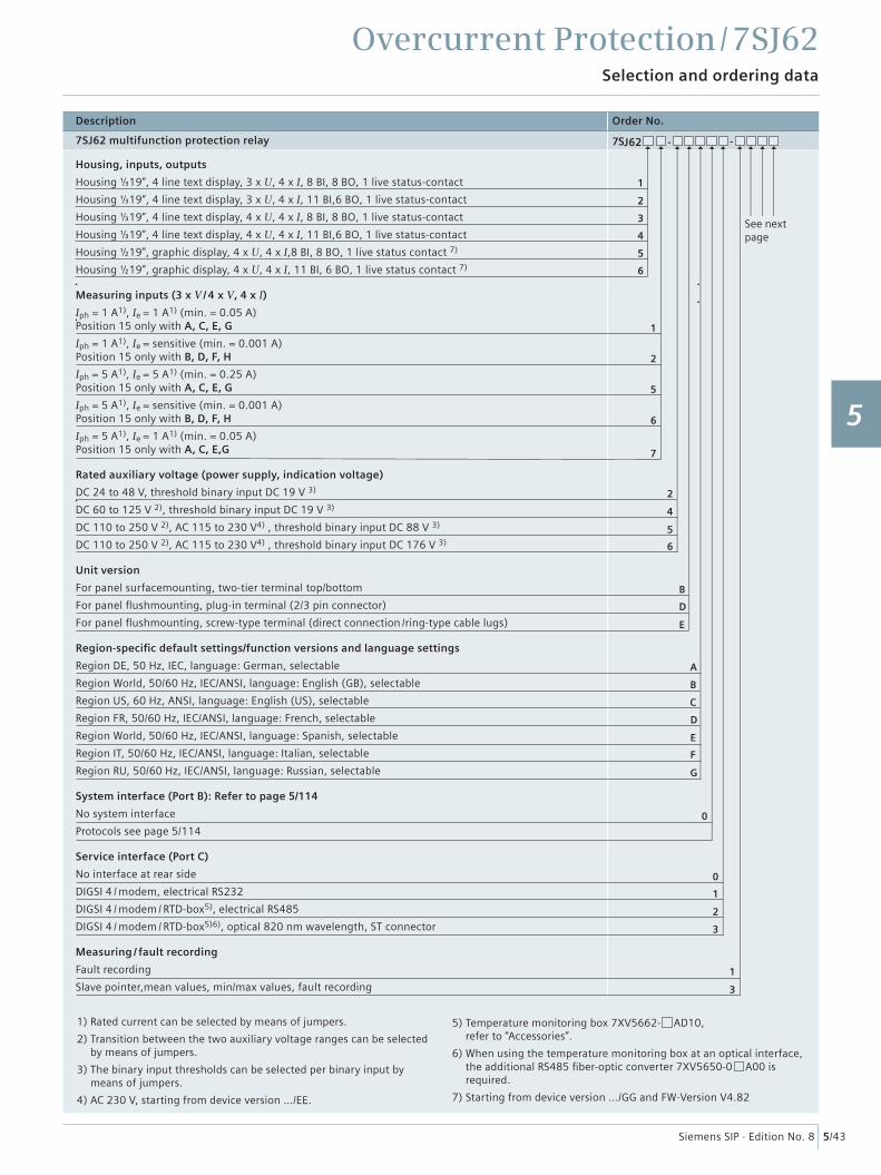
Description Order No.
7SJ62 multifunction protection relay 7SJ62 - -
Housing, inputs, outputs
Housing ⅓19”, 4 line text display, 3 x U, 4 x I, 8 BI, 8 BO, 1 live status-contact
Housing ⅓19”, 4 line text display, 3 x U, 4 x I, 11 BI,6 BO, 1 live status-contact
Housing ⅓19”, 4 line text display, 4 x U, 4 x I, 8 BI, 8 BO, 1 live status-contact
Housing ⅓19”, 4 line text display, 4 x U, 4 x I, 11 BI,6 BO, 1 live status-contact
Housing ½19”, graphic display, 4 x U, 4 x I,8 BI, 8 BO, 1 live status contact 7)
Housing ½19”, graphic display, 4 x U, 4 x I, 11 BI, 6 BO, 1 live status contact 7)
Measuring inputs (3 x V / 4 x V, 4 x I)
Iph = 1 A1), Ie = 1 A1) (min. = 0.05 A)Position 15 only with A, C, E, G
Iph = 1 A1), Ie = sensitive (min. = 0.001 A)Position 15 only with B, D, F, H
Iph = 5 A1), Ie = 5 A1) (min. = 0.25 A)Position 15 only with A, C, E, G
Iph = 5 A1), Ie = sensitive (min. = 0.001 A)Position 15 only with B, D, F, H
Iph = 5 A1), Ie = 1 A1) (min. = 0.05 A)Position 15 only with A, C, E,G
Rated auxiliary voltage (power supply, indication voltage)
DC 24 to 48 V, threshold binary input DC 19 V 3)
DC 60 to 125 V 2), threshold binary input DC 19 V 3)
DC 110 to 250 V 2), AC 115 to 230 V4) , threshold binary input DC 88 V 3)
DC 110 to 250 V 2), AC 115 to 230 V4) , threshold binary input DC 176 V 3)
Unit version
For panel surfacemounting, two-tier terminal top/bottom
For panel fl ushmounting, plug-in terminal (2/3 pin connector)
For panel fl ushmounting, screw-type terminal (direct connection / ring-type cable lugs)
Region-specifi c default settings/function versions and language settings
Region DE, 50 Hz, IEC, language: German, selectable
Region World, 50/60 Hz, IEC/ANSI, language: English (GB), selectable
Region US, 60 Hz, ANSI, language: English (US), selectable
Region FR, 50/60 Hz, IEC/ANSI, language: French, selectable
Region World, 50/60 Hz, IEC/ANSI, language: Spanish, selectable
Region IT, 50/60 Hz, IEC/ANSI, language: Italian, selectable
Region RU, 50/60 Hz, IEC/ANSI, language: Russian, selectable
System interface (Port B): Refer to page 5/114
No system interface
Protocols see page 5/114
Service interface (Port C)
No interface at rear side
DIGSI 4 / modem, electrical RS232
DIGSI 4 / modem / RTD-box5), electrical RS485
DIGSI 4 / modem / RTD-box5)6), optical 820 nm wavelength, ST connector
Measuring / fault recording
Fault recording
Slave pointer,mean values, min/max values, fault recording
1
2
1
0
0
1
2
3
3
3
4
5
6
1
2
5
6
5
B
D
C
B
A
E
D
E
F
G
6
4
2
7
See nextpage
1) Rated current can be selected by means of jumpers.
2) Transition between the two auxiliary voltage ranges can be selected by means of jumpers.
3) The binary input thresholds can be selected per binary input by means of jumpers.
4) AC 230 V, starting from device version …/EE.
5) Temperature monitoring box 7XV5662- AD10, refer to “Accessories”.
6) When using the temperature monitoring box at an optical interface, the additional RS485 fi ber-optic converter 7XV5650-0 A00 is required.
7) Starting from device version .../GG and FW-Version V4.82
1
2
3
4
5
6
7
8
9
10
11
12
13
14
15
Overcurrent Protection / 7SJ62Selection and ordering data
5/44 Siemens SIP · Edition No. 8
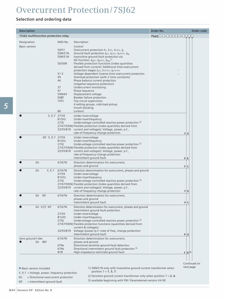
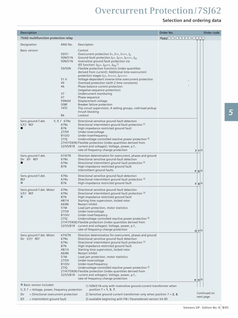
Description Order No. Order code
7SJ62 multifunction protection relay 7SJ62 - -
Designation ANSI No. Description
Basic version Control 50/51 Overcurrent protection I>, I>>, I>>>, Ip 50N/51N Ground-fault protection IE>, IE>>, IE>>>, IEp 50N/51N Insensitive ground-fault protection via IEE function: IEE>, IEE>>, IEEp
1)
50/50N Flexible protection functions (index quantities derived from current): Additional time-overcurrent protection stages I2>, I>>>>, IE>>>> 51 V Voltage-dependent inverse-time overcurrent protection 49 Overload protection (with 2 time constants) 46 Phase balance current protection (negative-sequence protection) 37 Undercurrent monitoring 47 Phase sequence 59N/64 Displacement voltage 50BF Breaker failure protection 74TC Trip circuit supervision 4 setting groups, cold-load pickup Inrush blocking 86 Lockout
V, P, f 27/59 Under-/overvoltage 81O/U Under-/overfrequency 27/Q Undervoltage-controlled reactive power protection 3)
27/47/59(N) Flexible protection (index quantities derived from 32/55/81R current and voltages): Voltage, power, p.f., rate-of-frequency-change protection
IEF V, P, f 27/59 Under-/overvoltage 81O/U Under-/overfrequency 27/Q Undervoltage-controlled reactive power protection 3)
27/47/59(N) Flexible protection (index quantities derived from 32/55/81R current and voltages): Voltage, power, p.f., rate-of-frequency-change protection Intermittent ground fault
Dir 67/67N Direction determination for overcurrent, phases and ground
Dir V, P, f 67/67N Direction determination for overcurrent, phases and ground 27/59 Under-/overvoltage 81O/U Under-/overfrequency 27/Q Undervoltage-controlled reactive power protection 3)
27/47/59(N) Flexible protection (index quantities derived from 32/55/81R current and voltages): Voltage, power, p.f., rate-of-frequency-change protection
Dir IEF 67/67N Direction determination for overcurrent, phases and ground Intermittent ground fault
Dir V,P,f IEF 67/67N Direction determination for overcurrent, phases and ground Intermittent ground fault protection 27/59 Under-/overvoltage 81U/O Under-/overfrequency 27/Q Undervoltage-controlled reactive power protection 3)
27/47/59(N) Flexible protection functions (quantities derived from current & voltages): 32/55/81R Voltage-/power-/p.f.-/rate of freq. change-protection
Intermittent ground-fault
Sens.ground-f.det. 67/67N Direction determination for overcurrent, Dir REF phases and ground
67Ns Directional sensitive ground-fault detection 67Ns Directional intermittent ground fault protection 3)
87N High-impedance restricted ground fault F D 2)
P G
P C
F G
F E
F C
P E
Basic version included
V, P, f = Voltage, power, frequency protection
Dir = Directional overcurrent protection
IEF = Intermittent ground fault
1) 50N/51N only with insensitive ground-current transformer when position 7 = 1, 5, 7.
2) Sensitive ground-current transformer only when position 7 = 2, 6.
3) available beginning with FW / Parameterset-version V4.90
Continued on next page
1
2
3
4
5
6
7
8
9
10
11
12
13
14
15
Overcurrent Protection / 7SJ62Selection and ordering data
5/45Siemens SIP · Edition No. 8
Description Order No. Order code
7SJ62 multifunction protection relay 7SJ62 - -
Designation ANSI No. Description
Basic version Control 50/51 Overcurrent protection I>, I>>, I>>>, Ip 50N/51N Ground-fault protection IE>, IE>>, IE>>>, IEp 50N/51N Insensitive ground-fault protection via IEE function: IEE>, IEE>>, IEEp
1)
50/50N Flexible protection functions (index quantities derived from current): Additional time-overcurrent protection stages I2>, I>>>>, IE>>>> 51 V Voltage-dependent inverse-time overcurrent protection 49 Overload protection (with 2 time constants) 46 Phase balance current protection (negative-sequence protection) 37 Undercurrent monitoring 47 Phase sequence 59N/64 Displacement voltage 50BF Breaker failure protection 74TC Trip circuit supervision, 4 setting groups, cold-load pickup Inrush blocking 86 Lockout
Sens.ground-f.det. V, P, f 67Ns Directional sensitive ground-fault detectionV,P,f REF 67Ns Directional intermittent ground fault protection 3)
87N High-impedance restricted ground fault 27/59 Under-/overvoltage 81O/U Under-/overfrequency 27/Q Undervoltage-controlled reactive power protection 3)
27/47/59(N) Flexible protection (index quantities derived from 32/55/81R current and voltages): Voltage, power, p.f., rate-of-frequency-change protection
Sens.ground-f.det. 67/67N Direction determination for overcurrent, phases and groundDir IEF REF 67Ns Directional sensitive ground-fault detection
67Ns Directional intermittent ground fault protection 3)
87N High-impedance restricted ground fault Intermittent ground faults
Sens.ground-f.det. 67Ns Directional sensitive ground-fault detectionREF 67Ns Directional intermittent ground fault protection 3)
87N High-impedance restricted ground fault
Sens.ground-f.det. Motor 67Ns Directional sensitive ground-fault detectionV,P,f REF 67Ns Directional intermittent ground fault protection 3)
87N High-impedance restricted ground fault 48/14 Starting time supervision, locked rotor 66/86 Restart inhibit 51M Load jam protection, motor statistics 27/59 Under-/overvoltage 81O/U Under-/overfrequency 27/Q Undervoltage-controlled reactive power protection 3)
27/47/59(N) Flexible protection (index quantities derived from 32/55/81R current and voltages): Voltage, power, p.f., rate-of-frequency-change protection
Sens.ground-f.det. Motor 67/67N Direction determination for overcurrent, phases and ground Dir V,P,f REF 67Ns Directional sensitive ground-fault detection 67Ns Directional intermittent ground fault protection 3)
87N High-impedance restricted ground fault 48/14 Starting time supervision, locked rotor 66/86 Restart inhibit 51M Load jam protection, motor statistics 27/59 Under-/overvoltage 81O/U Under-/overfrequency 27/Q Undervoltage-controlled reactive power protection 3)
27/47/59(N) Flexible protection (index quantities derived from 32/55/81R current and voltages): Voltage, power, p.f., rate-of-frequency-change protection H H 2)
H F 2)
F B 2)
Basic version included
V, P, f = Voltage, power, frequency protection
Dir = Directional overcurrent protection
IEF = Intermittent ground fault
1) 50N/51N only with insensitive ground-current transformer when position 7 = 1, 5, 7.
2) Sensitive ground-current transformer only when position 7 = 2, 6.
3) available beginning with FW / Parameterset-version V4.90
Continued on next page
P D 2)
F F 2)
1
2
3
4
5
6
7
8
9
10
11
12
13
14
15
Overcurrent Protection / 7SJ62Selection and ordering data
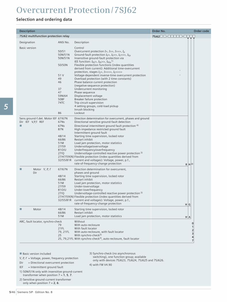
5/46 Siemens SIP · Edition No. 8
Description Order No. Order code
7SJ62 multifunction protection relay 7SJ62 - -
Designation ANSI No. Description
Basic version Control 50/51 Overcurrent protection I>, I>>, I>>>, Ip 50N/51N Ground-fault protection IE>, IE>>, IE>>>, IEp 50N/51N Insensitive ground-fault protection via IEE function: IEE>, IEE>>, IEEp
1)
50/50N Flexible protection functions (index quantities derived from current): Additional time-overcurrent protection, stages I2>, I>>>>, IE>>>> 51 V Voltage-dependent inverse-time overcurrent protection 49 Overload protection (with 2 time constants) 46 Phase balance current protection (negative-sequence protection) 37 Undercurrent monitoring 47 Phase sequence 59N/64 Displacement voltage 50BF Breaker failure protection 74TC Trip circuit supervision 4 setting groups, cold-load pickup Inrush blocking 86 Lockout
Sens.ground-f.det. Motor IEF 67/67N Direction determination for overcurrent, phases and groundDir IEF V,P,f REF 67Ns Directional sensitive ground-fault detection
67Ns Directional intermittent ground fault protection 4)
87N High-impedance restricted ground fault Intermittent ground fault 48/14 Starting time supervision, locked rotor 66/86 Restart inhibit 51M Load jam protection, motor statistics 27/59 Undervoltage/overvoltage 81O/U Underfrequency/overfrequency 27/Q Undervoltage-controlled reactive power protection 3)
27/47/59(N) Flexible protection (index quantities derived from 32/55/81R current and voltages): Voltage, power, p.f., rate-of-frequency-change protection
Motor V, P, f 67/67N Direction determination for overcurrent, Dir phases and ground 48/14 Starting time supervision, locked rotor 66/86 Restart inhibit 51M Load jam protection, motor statistics 27/59 Under-/overvoltage 81O/U Under-/overfrequency 27/Q Undervoltage-controlled reactive power protection 3)
27/47/59(N) Flexible protection (index quantities derived from 32/55/81R current and voltages): Voltage, power, p.f., rate-of-frequency-change protection
Motor 48/14 Starting time supervision, locked rotor 66/86 Restart inhibit 51M Load jam protection, motor statistics
ARC, fault locator, synchro-check Without 79 With auto-reclosure 21FL With fault locator 79, 21FL With auto-reclosure, with fault locator 25 With synchro-check3) 25, 79,21FL With synchro-check3), auto-reclosure, fault locator
012347
H A
H G
Basic version included
V, P, f = Voltage, power, frequency protection
Dir = Directional overcurrent protection
IEF = Intermittent ground fault
1) 50N/51N only with insensitive ground-current transformer when position 7 = 1, 5, 7.
2) Sensitive ground-current transformer only when position 7 = 2, 6.
3) Synchro-check (no asynchronousswitching), one function group; availableonly with devices 7SJ623, 7SJ624, 7SJ625 and 7SJ626.
4) with FW V4.90
R H 2)
1
2
3
4
5
6
7
8
9
10
11
12
13
14
15
Overcurrent Protection / 7SJ62Selection and ordering data
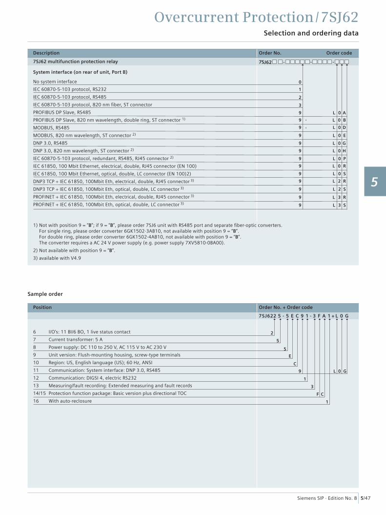
5/47Siemens SIP · Edition No. 8
Description Order No. Order code
7SJ62 multifunction protection relay 7SJ62 - - -
System interface (on rear of unit, Port B)
No system interface
IEC 60870-5-103 protocol, RS232
IEC 60870-5-103 protocol, RS485
IEC 60870-5-103 protocol, 820 nm fi ber, ST connector
PROFIBUS DP Slave, RS485
PROFIBUS DP Slave, 820 nm wavelength, double ring, ST connector 1)
MODBUS, RS485
MODBUS, 820 nm wavelength, ST connector 2)
DNP 3.0, RS485
DNP 3.0, 820 nm wavelength, ST connector 2)
IEC 60870-5-103 protocol, redundant, RS485, RJ45 connector 2)
IEC 61850, 100 Mbit Ethernet, electrical, double, RJ45 connector (EN 100)
IEC 61850, 100 Mbit Ethernet, optical, double, LC connector (EN 100)2)
DNP3 TCP + IEC 61850, 100Mbit Eth, electrical, double, RJ45 connector 3)
DNP3 TCP + IEC 61850, 100Mbit Eth, optical, double, LC connector 3)
PROFINET + IEC 61850, 100Mbit Eth, electrical, double, RJ45 connector 3)
PROFINET + IEC 61850, 100Mbit Eth, optical, double, LC connector 3)
1) Not with position 9 = “B”; if 9 = “B”, please order 7SJ6 unit with RS485 port and separate fi ber-optic converters.For single ring, please order converter 6GK1502-3AB10, not available with position 9 = “B”.For double ring, please order converter 6GK1502-4AB10, not available with position 9 = “B”.The converter requires a AC 24 V power supply (e.g. power supply 7XV5810-0BA00).
2) Not available with position 9 = “B”.
3) available with V4.9
Position Order No. + Order code
7SJ622 5 - 5 E C 9 1 - 3 F A 1 + L 0 G
6 I/O’s: 11 BI/6 BO, 1 live status contact
7 Current transformer: 5 A
8 Power supply: DC 110 to 250 V, AC 115 V to AC 230 V
9 Unit version: Flush-mounting housing, screw-type terminals
10 Region: US, English language (US); 60 Hz, ANSI
11 Communication: System interface: DNP 3.0, RS485
12 Communication: DIGSI 4, electric RS232
13 Measuring/fault recording: Extended measuring and fault records
14/15 Protection function package: Basic version plus directional TOC
16 With auto-reclosure
L 2 R
L 2 S
L 3 R
L 3 S
L 0 R
L 0 P
L 0 H
L 0 G
L 0 E
L 0 D
L 0 B
L 0 A
9
9
9
9
9
9
9
1
1
9
3
3
F C
L 0 G
9
2
E
C
9
9
1
5
9
0
5
2
9
Sample order
L 0 S9
1
2
3
4
5
6
7
8
9
10
11
12
13
14
15
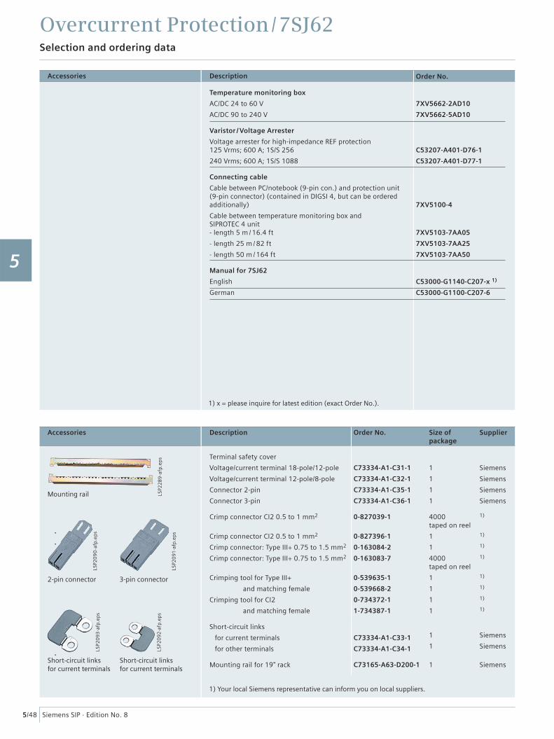
Overcurrent Protection / 7SJ62Selection and ordering data
5/48 Siemens SIP · Edition No. 8
Description Order No.
Temperature monitoring box
AC/DC 24 to 60 V
AC/DC 90 to 240 V
7XV5662-2AD10
7XV5662-5AD10
Varistor / Voltage Arrester
Voltage arrester for high-impedance REF protection125 Vrms; 600 A; 1S/S 256
240 Vrms; 600 A; 1S/S 1088
C53207-A401-D76-1
C53207-A401-D77-1
Connecting cable
Cable between PC/notebook (9-pin con.) and protection unit (9-pin connector) (contained in DIGSI 4, but can be ordered additionally)
Cable between temperature monitoring box and SIPROTEC 4 unit- length 5 m / 16.4 ft
- length 25 m / 82 ft
- length 50 m / 164 ft
7XV5100-4
7XV5103-7AA05
7XV5103-7AA25
7XV5103-7AA50
Manual for 7SJ62
English
German
C53000-G1140-C207-x 1)
C53000-G1100-C207-6
1) x = please inquire for latest edition (exact Order No.).
Accessories
Short-circuit linksfor current terminals
Short-circuit linksfor current terminals
2-pin connector 3-pin connector
Mounting rail
LSP2
093
-afp
.ep
s
LSP2
092
-afp
.ep
s
LSP2
09
0-a
fp.e
ps
LSP2
091
-afp
.ep
s
LSP2
28
9-a
fp.e
ps
Description Order No. Size ofpackage
Supplier
Terminal safety cover
Voltage/current terminal 18-pole/12-pole
Voltage/current terminal 12-pole/8-pole
Connector 2-pin
Connector 3-pin
C73334-A1-C31-1
C73334-A1-C32-1
C73334-A1-C35-1
C73334-A1-C36-1
1
1
1
1
Siemens
Siemens
Siemens
Siemens
Crimp connector CI2 0.5 to 1 mm2
Crimp connector CI2 0.5 to 1 mm2
Crimp connector: Type III+ 0.75 to 1.5 mm2
Crimp connector: Type III+ 0.75 to 1.5 mm2
Crimping tool for Type III+
and matching female
Crimping tool for CI2
and matching female
0-827039-1
0-827396-1
0-163084-2
0-163083-7
0-539635-1
0-539668-2
0-734372-1
1-734387-1
4000taped on reel
1
1
4000taped on reel
1
1
1
1
1)
1)
1)
1)
1)
1)
1)
1)
Short-circuit links
for current terminals
for other terminals
C73334-A1-C33-1
C73334-A1-C34-1
1
1
Siemens
Siemens
Mounting rail for 19" rack C73165-A63-D200-1 1 Siemens
1) Your local Siemens representative can inform you on local suppliers.
Accessories
1
2
3
4
5
6
7
8
9
10
11
12
13
14
15
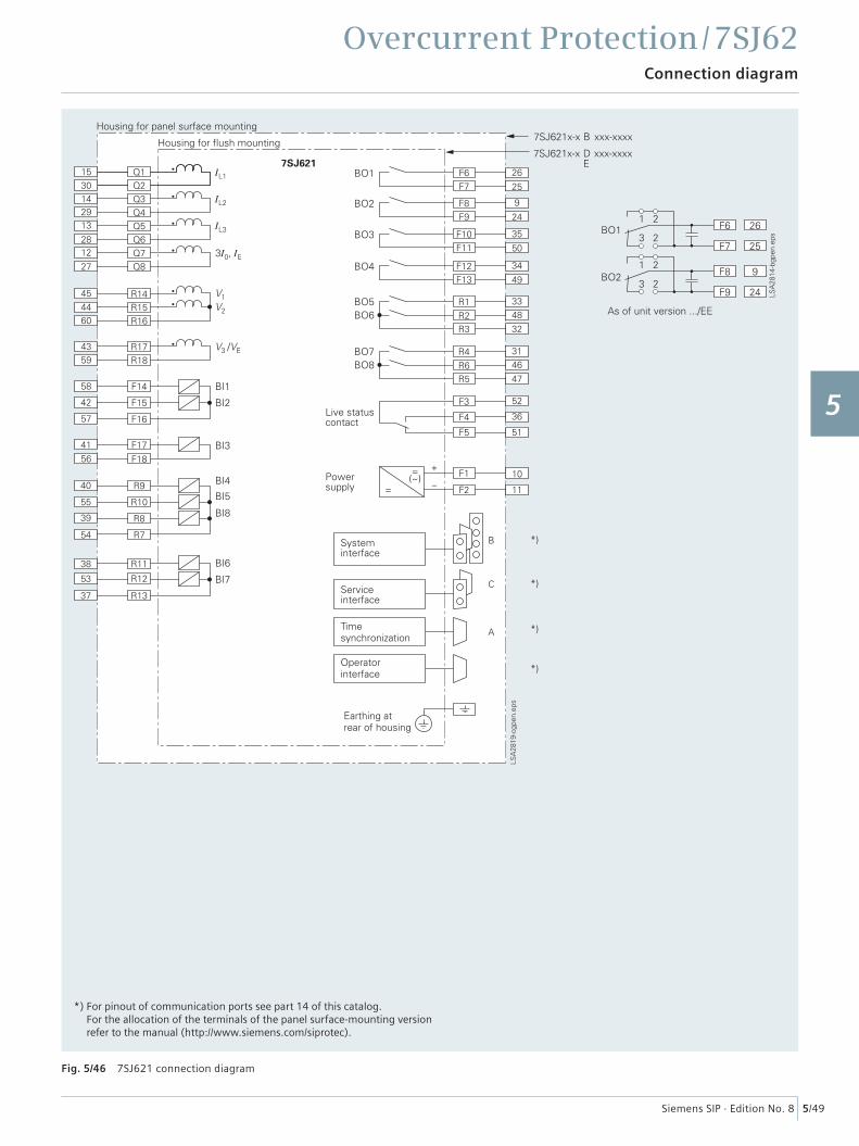
Overcurrent Protection / 7SJ62Connection diagram
5/49Siemens SIP · Edition No. 8
Fig. 5/46 7SJ621 connection diagram
*) For pinout of communication ports see part 14 of this catalog.For the allocation of the terminals of the panel surface-mounting versionrefer to the manual (http://www.siemens.com/siprotec).
1
2
3
4
5
6
7
8
9
10
11
12
13
14
15
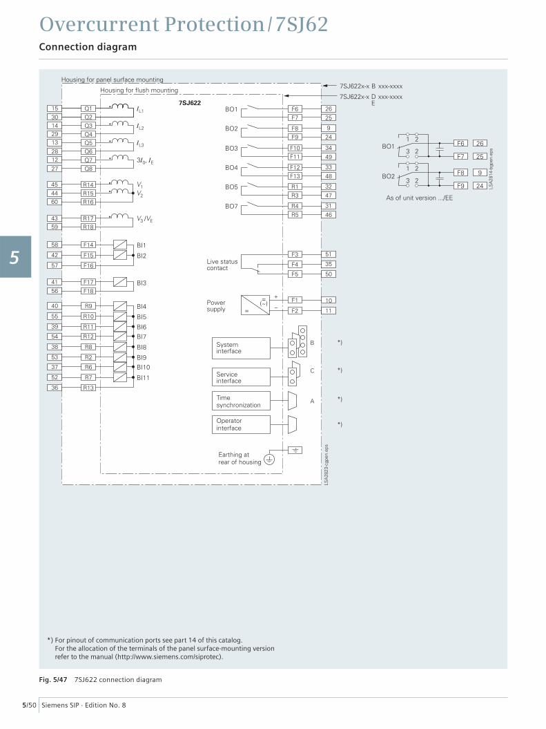
Overcurrent Protection / 7SJ62Connection diagram
5/50 Siemens SIP · Edition No. 8
Fig. 5/47 7SJ622 connection diagram
*) For pinout of communication ports see part 14 of this catalog.For the allocation of the terminals of the panel surface-mounting versionrefer to the manual (http://www.siemens.com/siprotec).
1
2
3
4
5
6
7
8
9
10
11
12
13
14
15
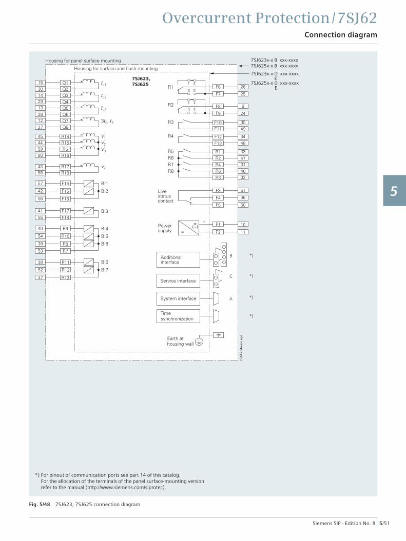
Overcurrent Protection / 7SJ62Connection diagram
5/51Siemens SIP · Edition No. 8
Fig. 5/48 7SJ623, 7SJ625 connection diagram
7SJ623,7SJ625
7SJ623x-x B xxx-xxxx7SJ625x-x B xxx-xxxx
7SJ623x-x D xxx-xxxxE
E7SJ625x-x D xxx-xxxx
LSA
47
34
a-en
.ep
s
*) For pinout of communication ports see part 14 of this catalog.For the allocation of the terminals of the panel surface-mounting versionrefer to the manual (http://www.siemens.com/siprotec).
1
2
3
4
5
6
7
8
9
10
11
12
13
14
15
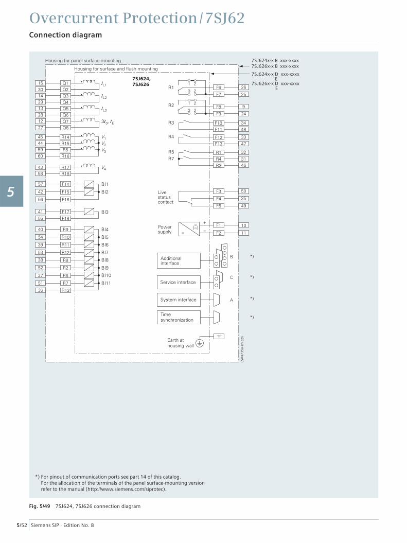
Overcurrent Protection / 7SJ62Connection diagram
5/52 Siemens SIP · Edition No. 8
Fig. 5/49 7SJ624, 7SJ626 connection diagram
LSA
47
35
a-en
.ep
s
7SJ624,7SJ626
7SJ624x-x B xxx-xxxx7SJ626x-x B xxx-xxxx
7SJ624x-x D xxx-xxxxE
E7SJ626x-x D xxx-xxxx
*) For pinout of communication ports see part 14 of this catalog.For the allocation of the terminals of the panel surface-mounting versionrefer to the manual (http://www.siemens.com/siprotec).
1
2
3
4
5
6
7
8
9
10
11
12
13
14
15