overhead transmission lines earthing - svenska kraftnät · · 2015-11-17overhead transmission...
TRANSCRIPT
SVENSKA KRAFTNÄT S W E D I S H N A T I O N A L G R I D
UNIT, BUSINESS AREA AFL - Asset Management, Lines
DATE 2015-11-01
OUR REFERENCE
TR05-13E
LTATIONS
/ /ST,Elect r icsafe ty TECHNICAL GUIDELINE f manager
REVISION
2
Overhead transmission lines Earthing
Introduction This Guideline is mainly intended to be used in procurement but can also be used for maintenance of overhead transmission lines.
This English text is to be regarded as a translation of the Swedish guideline. The Swe-dish text and the interpretation thereof shall govern the contract and the legal rela-tions between parties.
TEKNISK RIKTLINJE 2015-11-01 TR05-13E utg 2
1/31
TEKNISK RIKTLINJE 2015-11-01 TR05-13E utg 2
2/31
Revision Notes Change notes Date
1 This Guideline is a translation of Swedish version TR05-13 revision 2 and replaces TR5:113 EARTHING from 14 September, 2000.
2012-10-05
2 SS-EN 50522 replaced by TR01-13 in references. Table in clause 13.5.3.12 is changed according to Telestörn-ingsnämndens meddelande Nr 21. Links to clauses in 13.6.2 and 13.6.3 is corrected. Figure 6 is revised.
2015-11-01
TEKNISK RIKTLINJE 2015-11-01 TR05-13E utg 2
3/31
Content
13.1 References ............................................................................................................. 6
13.2 Scope ..................................................................................................................... 7
13.3 Definitions ............................................................................................................. 7
13.3.1 Earthing .................................................................................................. 713.3.2 Functional earthing ................................................................................ 713.3.3 Protective earthing ................................................................................. 713.3.4 Earth conductor ...................................................................................... 713.3.5 Earth electrode ........................................................................................ 813.3.6 Shallow earth electrode .......................................................................... 813.3.7 Deep earth electrode ............................................................................... 813.3.8 Radial earth electrode ............................................................................ 813.3.9 Counterpoise ........................................................................................... 813.3.10 Continuous counterpoise ........................................................................ 813.3.11 Local earth electrode .............................................................................. 813.3.12 Protective bonding conductor ................................................................ 813.3.13 Potential grading earth electrode .......................................................... 813.3.14 Earthing conductor................................................................................. 813.3.15 Down conductor...................................................................................... 913.3.16 Shield wire .............................................................................................. 913.3.17 Continuous shield wire ........................................................................... 913.3.18 Insulated shield wire .............................................................................. 9
13.4 Description ............................................................................................................ 9
13.4.1 General .................................................................................................... 913.4.2 Functional earthing ................................................................................ 913.4.3 Protective earthing ................................................................................. 913.4.4 Touch protection ................................................................................... 1013.4.5 Galvanic corrosion ............................................................................... 10
13.5 Requirements ....................................................................................................... 11
TEKNISK RIKTLINJE 2015-11-01 TR05-13E utg 2
4/31
13.5.1 Material .................................................................................................. 1113.5.1.1 Earthing conductor and shallow earth electrode ................... 1113.5.1.2 Deep earth electrode ................................................................ 1113.5.1.3 Potential grading earth electrode .......................................... 12
13.5.2 Electrical requirements ........................................................................ 1213.5.2.1 Shield wire ............................................................................... 1213.5.2.2 Counterpoise ........................................................................... 1213.5.2.3 Repair of continuous counterpoise and down conductors .... 1213.5.2.4 Functional earthing ................................................................ 1313.5.2.5 Protective earthing ................................................................. 1313.5.2.6 Touch protection ..................................................................... 13
13.5.3 Performance .......................................................................................... 1313.5.3.1 Earthing of different tower designs ....................................... 1313.5.3.2 Continuous counterpoise ........................................................ 1413.5.3.3 Radial earth electrode ............................................................. 1513.5.3.4 Deep earth electrode ............................................................... 1513.5.3.5 Potential grading earth electrode .......................................... 1513.5.3.6 Excavation depth .................................................................... 1613.5.3.7 Touch protection ..................................................................... 1613.5.3.8 Connection of earthing conductors to support and stays ...... 1613.5.3.9 Connection to down conductor ................................................1713.5.3.10 Connection and jointing underneath the ground surface ......1713.5.3.11 Connection of shield wire .........................................................1713.5.3.12 Crossings ................................................................................. 1813.5.3.13 Connection between overhead line and substation ............... 19
13.6 Check ................................................................................................................... 19
13.6.1 General .................................................................................................. 1913.6.2 Heavy current method .......................................................................... 1913.6.3 Light current method ............................................................................ 2013.6.4 Measurement of step and touch voltage .............................................. 2013.6.5 Functional check of spark-gap and stay insulator .............................. 20
13.7 Delivery ............................................................................................................... 20
13.8 Figures ................................................................................................................. 22
13.8.1 Figure 1 .................................................................................................. 22
TEKNISK RIKTLINJE 2015-11-01 TR05-13E utg 2
5/31
13.8.2 Figure 2 ................................................................................................. 2313.8.3 Figure 3 ................................................................................................. 2313.8.4 Figure 4 ................................................................................................. 2413.8.5 Figure 5 ................................................................................................. 2413.8.6 Figure 6 ................................................................................................. 2513.8.7 Figure 7 ................................................................................................. 2613.8.8 Figure 8 ................................................................................................. 2713.8.9 Figure 9 ................................................................................................. 2813.8.10 Figure 10 ............................................................................................... 2913.8.11 Figure 11 ................................................................................................ 3013.8.12 Figure 12 ................................................................................................ 31
TEKNISK RIKTLINJE 2015-11-01 TR05-13E utg 2
6/31
13.1 References
Note that standards, regulations, guidelines etc., referred to in this guideline are con-
stantly changing and may be discontinued, revised or superseded. It is for the contrac-
tor to promptly denounce such changes. Following list comprise of documents re-
ferred to in this guideline but also documents that can be of interest.
SS-EN ISO 9001:2008 Quality management systems - Requirements (ISO 9001:2008)
SFS 2009:22 Starkströmsförordning
ELSÄK-FS 2008:1 Elsäkerhetsverkets föreskrifter och allmänna råd om hur elektriska starkströmsanläggningar ska vara utförda
SvK-TR01-01 Stamnätsanläggningar (in Swedish)
SvK-TR01-13 Stamnätsstationer Jordning
SvK-TR05-04E Overhead transmission lines, Conductors
SvK-TR08-04 Dokumentationsinnehåll och teknisk data för ledningar (in Swedish)
SvK-TR10-01 Svenska kraftnäts kompletterande elsäkerhetsanvisning (in Swedish)
SvK-TR10-05 Elektriska och icke elektriska anläggningar invid Svenska kraftnäts anläggningar (in Swedish)
SS-EN 50341-1 Overhead electrical lines exceeding AC 45 kV
SS-EN 61936-1 Power installations exceeding 1 kV a.c. – Part 1: Common rules
SS 436 21 10 Installations for grounding switchgear with nominal volt-age above 1 kV
EBR K25 Jordningskonstruktioner distributionsnät och nätstationer 0,4-24 kV
EBR U301E Underhåll ledningar 0,4 - 420 kV - Jordning
TEKNISK RIKTLINJE 2015-11-01 TR05-13E utg 2
7/31
EBR U303H Underhåll ledningar 0,4 - 420 kV - Besiktning, jordnings-kontroll
EBR U602.5 Underhåll stationer 12-420 kV - Jordningskontroll
Ref. 1 Underhåll kraftledningar över 24 kV - VAST-Vattenfall
Ref. 2 Jordning av 11 - 400 kV luftledningar - Huvudprinci-per - VAST - Vattenfall - Elverksföreningen
13.2 Scope
These rules apply to earthing of overhead lines and give a general indication of how
functional and protective earthing must be carried out in solidly earthed neutral AC
system overhead transmission lines for HVAC with towers made of electrically conduc-
tive and non-conductive materials. These guidelines can also be used for HVDC over-
head transmission lines.
13.3 Definitions
13.3.1 Earthing Electrically conductive connection between the construction part and the surrounding
soil. Most earthing combines the two purposes as functional earthing and protective
earthing. For example a line with a continuous shield wire the earthing is a single
coherent system with these two properties.
13.3.2 Functional earthing Earthing to divert lightning currents and 50-periodic fault currents so safe tripping is
obtained.
13.3.3 Protective earthing Earthing a point or points in a system or in an installation or in equipment, for pur-
poses of electrical safety for protection against electric shock from step and touch volt-
age.
13.3.4 Earth conductor Conductor forming a part of the fixed installation for earthing purposes.
TEKNISK RIKTLINJE 2015-11-01 TR05-13E utg 2
8/31
13.3.5 Earth electrode Conductor located in the earth designed to give an electrically conductive connection
with the surrounding soil layers. The conductor can consist of rod, wire, sheet-metal
or equivalent.
13.3.6 Shallow earth electrode Earth electrode consisting of a continuous counterpoise, radial earth electrode or oth-
erwise to the surface parallel located earth conductors down to a depth of about 1 m.
Continuous counterpoise is in principle a shallow earth electrode but is not comprised
in this guideline when shallow earth electrode is mentioned.
13.3.7 Deep earth electrode Earth electrode consisting of vertically placed earth electrode buried or driven down in
the soil at a greater depth than 1 m.
13.3.8 Radial earth electrode Horizontally radially placed earth conductors in the soil.
13.3.9 Counterpoise Conductor or combination of conductors buried in the ground and electrically connect-
ing the footings of the supports of the towers.
13.3.10 Continuous counterpoise Conductor buried in the ground electrically connecting the footings of the supports of
the towers along an overhead line.
13.3.11 Local earth electrode Earth electrode comprising deep earth electrode, radial earth electrode or a combina-
tion thereof.
13.3.12 Protective bonding conductor Conductor provided for protective-equipotential-bonding.
13.3.13 Potential grading earth electrode Protective earthing consisting of a protective bonding conductor in the soil around
structure and/or stay anchors.
13.3.14 Earthing conductor Conductor between an earth electrode and an earth terminal or, if such terminal is
missing, between an earth electrode and a construction part that shall be earthed.
TEKNISK RIKTLINJE 2015-11-01 TR05-13E utg 2
9/31
13.3.15 Down conductor Conductor for connection of insulator string attachments, crossarm and shield wire to
a fixed earth terminal on the tower.
13.3.16 Shield wire Conductor, horizontally located in an overhead line, usually located above the phase
conductors. The shield wire is part of the earthing system, but could be connected to
the substation earth via a spark gap.
13.3.17 Continuous shield wire Shield wire located along the entire length of overhead lines.
13.3.18 Insulated shield wire Shield wire electrically separated from the tower with insulators.
13.4 Description
13.4.1 General An installation being a part of a solidly earthed neutral system shall be designed so an
earth fault instantaneous and automatically is switched off and that elevated ground
potentials caused by the earth fault is levelled out, so that necessary security is ob-
tained for person and property. This is achieved by functional and protective earthing.
See ELSÄK-FS 2008:1 and changing regulation ELSÄK-FS 2010:1.
Earthing of a line is determined both by the individual towers earthing and the connec-
tion via continuous counterpoise and shield wire. A tower placed on rock can be al-
lowed not to have an earthing conductor if the electrical connection to the shield wire
is guaranteed. This connection is then used for protective earthing and to some extent
functional earthing from nearby tower. Normally shall, for individual towers, the earth
resistance be below 100 .
13.4.2 Functional earthing Functional earthing shall be accomplished with shallow earth electrode or deep earth
electrode, with regard to the circumstances regarding terrain, obstacles, etc.
13.4.3 Protective earthing Protective earthing shall be carried out at towers and stay anchors where people usual-
ly travel or stay, so that no unallowable step and touch voltages arise.
TEKNISK RIKTLINJE 2015-11-01 TR05-13E utg 2
10/31
Protective earthing shall, if earth electrode for functional earthing is not enough, be
carried out by a potential grading earth electrode (see clause 0) surrounding the ex-
posed conductive part and connected to this.
Protective earthing shall be connected directly to exposed-conductive-part and not via
spark-gap.
In some places (beaches, playgrounds, sports fields, parking lots and the like), addi-
tional actions may be necessary like touch protection according to clause 13.4.4.
13.4.4 Touch protection Touch protection of Svenska kraftnäts towers can be made if the protective earthing
cannot be made with enough safety. Svenska kraftnät shall approve proposed solution.
Touch protection is carried out by placing insulation on the exposed conductive parts,
which are accessible to touch from the ground. Protective earthing can also be com-
pletely avoided by selecting the supports and cabinets in plastic. But Svenska kraftnät
does not use support in plastic.
Note Touch protection is normally carried out in places as described in clause 13.4.3. Example of a touch protection is a plastic covering of pole.
13.4.5 Galvanic corrosion Measures shall be taken to prevent corrosion of the buried steel components which are
electrically connected to earth conductor of copper or copper-clad steel.
Metallic contact between copper and other metals beneath the ground surface is not
allowed. All these connections must be made above the ground surface.
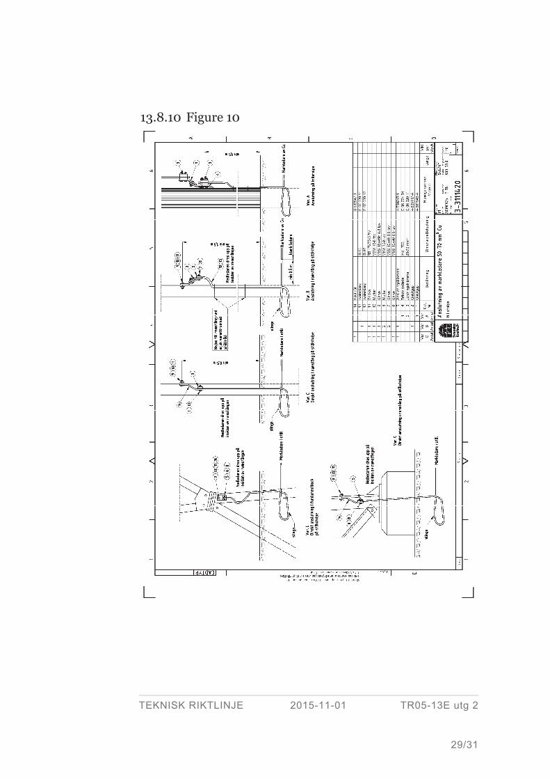
When earth electrode or earthing conductor of copper or copper-clad steel is used, the
conductors shall be connected to the tower or stay via a spark-gap (see Figure 10 and
Figure 11). In exceptional circumstances, stay insulator, can be used but they should
be avoided in new designs.
Normal practice is to connect the shield wires via spark-gaps to the substation in order
not to connect the substation copper earth system to the line towers. These spark-gaps
have an ignition voltage of about 20 kV. In this respect, greater stress on counterpoise
occurs in the first spans at earth faults. See furthermore Figure 6 – Figure 9.
If earth electrodes and earth conductors is made of steel or if the whole line consist of
tower or stay where NO details have direct contact with the soil (e.g. towers on con-
crete foundations without stays) the spark-gaps can be omitted both for connection to
TEKNISK RIKTLINJE 2015-11-01 TR05-13E utg 2
11/31
counterpoise and shield wires to the substations even if earth electrodes is made of
copper or copper-clad steel wires.
Protective earthing, is normally carried out with galvanized steel wire, is never con-
nected via spark-gap.
13.5 Requirements
13.5.1 Material
13.5.1.1 Earthing conductor and shallow earth electrode Earthing conductors for location in the soil shall be of copper, copper-clad steel or
galvanized steel. For the copper-clad steel wire its conductivity is given relative to pure
copper in accordance with “International Annealed Copper Standard”, IACS. Normal-
ly, copper-clad steel wire and strand shall be annealed and with a conductivity of 40 %
IACS. The copper layer on the copper-clad steel shall be at least 0,25 mm thick in
accordance with SS 436 21 10 and shall be attached to the steel in such a manner as to
resist the arising stresses without separating from the steel.
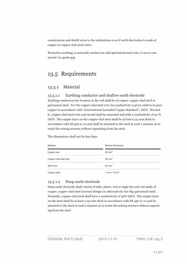
The dimensions shall not be less than:
13.5.1.2 Deep earth electrode Deep earth electrode shall consist of tube, plates, rod or angle bar and rod made of
copper, copper-clad steel (normal design) or alternatively hot-dip galvanized steel.
Normally, copper-clad steel shall have a conductivity of 40% IACS. The copper layer
on the steel shall be at least 0,25 mm thick in accordance with SS 436 21 10 and be
attached to the steel in such a manner as to resist the arising stresses without separat-
ing from the steel.
Material Minimal Dimension
Copper wire 35 mm2
Copper-clad steel wire 35 mm2
Steel wire 50 mm2
Copper plate 1 mm × 0,5 m2
TEKNISK RIKTLINJE 2015-11-01 TR05-13E utg 2
12/31
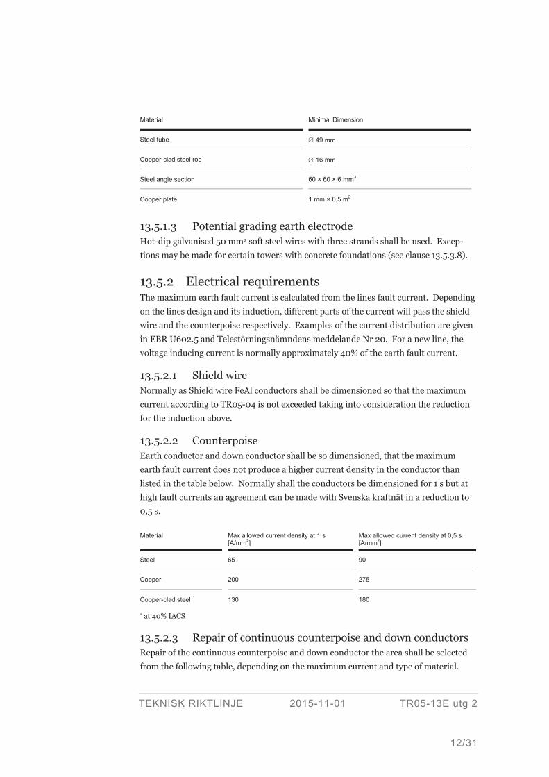
Material Minimal Dimension
Steel tube 49 mm
Copper-clad steel rod 16 mm
Steel angle section 60 × 60 × 6 mm3
Copper plate 1 mm × 0,5 m2
13.5.1.3 Potential grading earth electrode Hot-dip galvanised 50 mm2 soft steel wires with three strands shall be used. Excep-
tions may be made for certain towers with concrete foundations (see clause 13.5.3.8).
13.5.2 Electrical requirements The maximum earth fault current is calculated from the lines fault current. Depending
on the lines design and its induction, different parts of the current will pass the shield
wire and the counterpoise respectively. Examples of the current distribution are given
in EBR U602.5 and Telestörningsnämndens meddelande Nr 20. For a new line, the
voltage inducing current is normally approximately 40% of the earth fault current.
13.5.2.1 Shield wire Normally as Shield wire FeAl conductors shall be dimensioned so that the maximum
current according to TR05-04 is not exceeded taking into consideration the reduction
for the induction above.
13.5.2.2 Counterpoise Earth conductor and down conductor shall be so dimensioned, that the maximum
earth fault current does not produce a higher current density in the conductor than
listed in the table below. Normally shall the conductors be dimensioned for 1 s but at
high fault currents an agreement can be made with Svenska kraftnät in a reduction to
0,5 s.
Material Max allowed current density at 1 s [A/mm2]
Max allowed current density at 0,5 s [A/mm2]
Steel 65 90
Copper 200 275
Copper-clad steel * 130 180
* at 40% IACS
13.5.2.3 Repair of continuous counterpoise and down conductors Repair of the continuous counterpoise and down conductor the area shall be selected
from the following table, depending on the maximum current and type of material.
TEKNISK RIKTLINJE 2015-11-01 TR05-13E utg 2
13/31
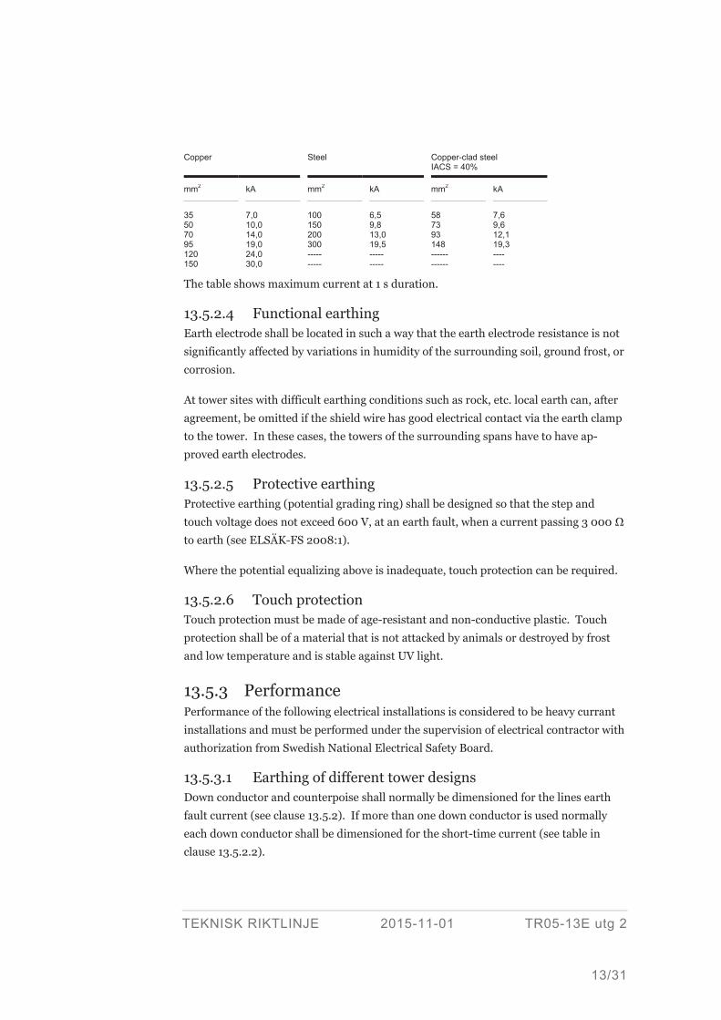
Copper Steel Copper-clad steel IACS = 40%
mm2 kA mm2 kA mm2 kA
35 50 70 95 120 150
7,0 10,0 14,0 19,0 24,0 30,0
100 150 200 300 ----- -----
6,5 9,8 13,0 19,5 ----- -----
58 73 93 148 ------ ------
7,6 9,6 12,1 19,3 ---- ----
The table shows maximum current at 1 s duration.
13.5.2.4 Functional earthing Earth electrode shall be located in such a way that the earth electrode resistance is not
significantly affected by variations in humidity of the surrounding soil, ground frost, or
corrosion.
At tower sites with difficult earthing conditions such as rock, etc. local earth can, after
agreement, be omitted if the shield wire has good electrical contact via the earth clamp
to the tower. In these cases, the towers of the surrounding spans have to have ap-
proved earth electrodes.
13.5.2.5 Protective earthing Protective earthing (potential grading ring) shall be designed so that the step and
touch voltage does not exceed 600 V, at an earth fault, when a current passing 3 000
to earth (see ELSÄK-FS 2008:1).
Where the potential equalizing above is inadequate, touch protection can be required.
13.5.2.6 Touch protection Touch protection must be made of age-resistant and non-conductive plastic. Touch
protection shall be of a material that is not attacked by animals or destroyed by frost
and low temperature and is stable against UV light.
13.5.3 Performance Performance of the following electrical installations is considered to be heavy currant
installations and must be performed under the supervision of electrical contractor with
authorization from Swedish National Electrical Safety Board.
13.5.3.1 Earthing of different tower designs Down conductor and counterpoise shall normally be dimensioned for the lines earth
fault current (see clause 13.5.2). If more than one down conductor is used normally
each down conductor shall be dimensioned for the short-time current (see table in
clause 13.5.2.2).
TEKNISK RIKTLINJE 2015-11-01 TR05-13E utg 2
14/31
Steel towers Functional earthing shall be made as continuous counterpoise.
Concrete towers Beam gantry, insulator mounts, and reinforcement must be connected to the tower
earth electrode down conductor in the tower. Normally one down conductor per pole
is used.
Wooden towers Earthing of wooden towers is made when requirements in SS-EN 50341 regarding the
wooden isolation length is not met. Beam gantry, insulator mounts, and reinforce-
ment must be connected to the tower earth electrode with down conductor. Normally
one down conductor per pole is used.
HVDC lines For HVDC line with steel towers local earth electrodes can be used instead of continu-
ous counterpoise. HVDC line is equipped, at new building, with a separate metallic
return conductor that is not to be used for earthing of towers.
13.5.3.2 Continuous counterpoise The earth conductor shall be buried in the ground between the boundaries formed by
the outer phase conductors and be continuous along the line. The earth conductor
shall be connected to the tower and all the stays at the towers it passes. For the exca-
vation depth see clause 13.5.3.6.
In the case of obstacles (rock, roads, railways etc.) which prevent the counterpoise
being buried between the boundaries of the outer phase conductors, the counterpoise
is to be arranged as follows:
> If the extent of the obstacle beyond the boundaries of the outer phase conductors
is small, the counterpoise is to be routed around it.
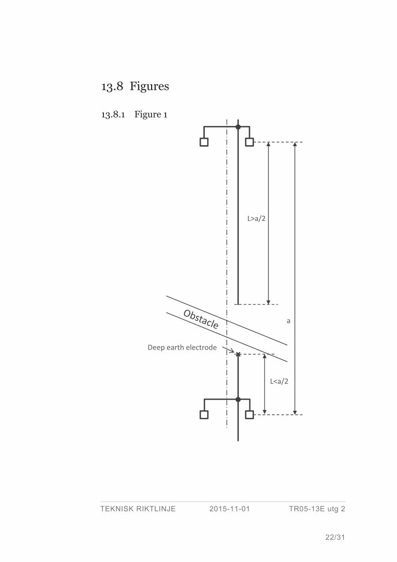
> If the obstacle extends to a significant distance perpendicular to the line, the con-
tinuous counterpoise is to be discontinued in the span. See Figure 1. This is not
valid for connection to a substation.
If a section with a continuous counterpoise is terminated before a tower area with local
earth electrode or if the continuous counterpoise is discontinued for obstacles, the
continuous counterpoise shall be extended to at least half the span from the last tower
area with a continuous counterpoise. If that is not possible continuous counterpoise
shall be terminated with a deep earth electrode. Only one break of the continuous
counterpoise per span is allowed.
For a connection to a substation no break is allowed on the continuous counterpoise
within 1 km from the substation.
TEKNISK RIKTLINJE 2015-11-01 TR05-13E utg 2
15/31
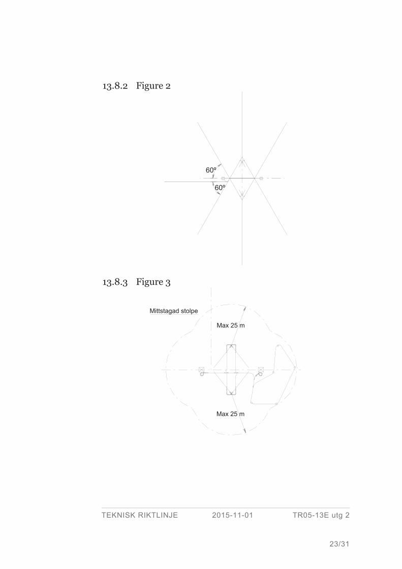
13.5.3.3 Radial earth electrode The earth conductor shall be placed horizontally and radially out from the object to be
earthed. The number of rays should be maximized to eight (8) pieces. The length of
the rays shall be adapted to the soil conductivity. See Figure 2 and for the excavation
depth see clause 13.5.3.6
The number and the length of the earth conductors included in the earth electrode
shall be so that the expected earth resistance is below 100 according to clause 13.4.1.
If necessary, a combination of radial and deep earth electrodes can be used in order to
obtain a sufficiently low earth resistance.
13.5.3.4 Deep earth electrode Earth conductor (rods) in accordance with 13.5.1.2 shall be driven vertically into the
ground and connected to the tower with horizontal conductors.
If so required, to obtain a sufficiently low earth resistance, several earth conductors
shall be installed, separated by a distance not less than the excavation depth, adjacent
to each other.
The vertical earth conductors shall be located within a distance of 25 m from the near-
est part of the object to be earthed. See Figure 3.
The number and the length of the vertical conductors shall be so that the expected
earth resistance is below 100 according to clause 13.4.1.
If necessary, a combination of radial and deep earth electrodes can be used in order to
obtain a sufficiently low earth resistance.
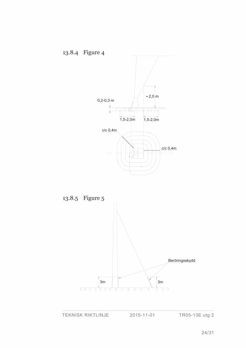
13.5.3.5 Potential grading earth electrode Potential grading earth electrode shall be located horizontally around stays and associ-
ated tower. For material selection, see 13.5.1.3, and for location, see Figure 4.
Potential grading earth electrode are available as two types:
> A simple variant positioned as a single loop, 1 lap and 1 m from the post/bar
around all the stays and tower legs. This design generally applies to poles in urban
areas and where tower are placed on concrete foundations.
> Potential grading earth electrode placed in a spiral as in Figure 4. This design
applies in places where people usually travel or stay.
Potential grading earth electrode shall be connected directly (without spark-gaps) to
tower and/or stay.
TEKNISK RIKTLINJE 2015-11-01 TR05-13E utg 2
16/31
At towers placed on rock where protective earthing cannot be arranged for the exposed
tower parts shall, which are accessible to touch, be touch-protected.
13.5.3.6 Excavation depth Earth conductor, for both continuous counterpoise and radial earth electrode, shall be
located at a minimum depth of 60 cm. However, in meadowland and arable land a
minimum depth of 80 cm shall be used.
In the presence of rock at a depth less than the above, earth conductor may be located
on the rock. However, only in exceptional cases may the earth conductor be laid on
surface rock. If the earth conductor is to be laid on surface rock it shall be placed in a
protecting pipe and bolted to the rock. As protecting pipe a pipe of SDR class PE 80
shall be used.
Earth conductor for Potential grading earth electrode shall be located at a depth of
20 – 30 cm.
13.5.3.7 Touch protection Insulation shall be applied to those parts which are accessible within 3 m from the
ground. See Figure 5.
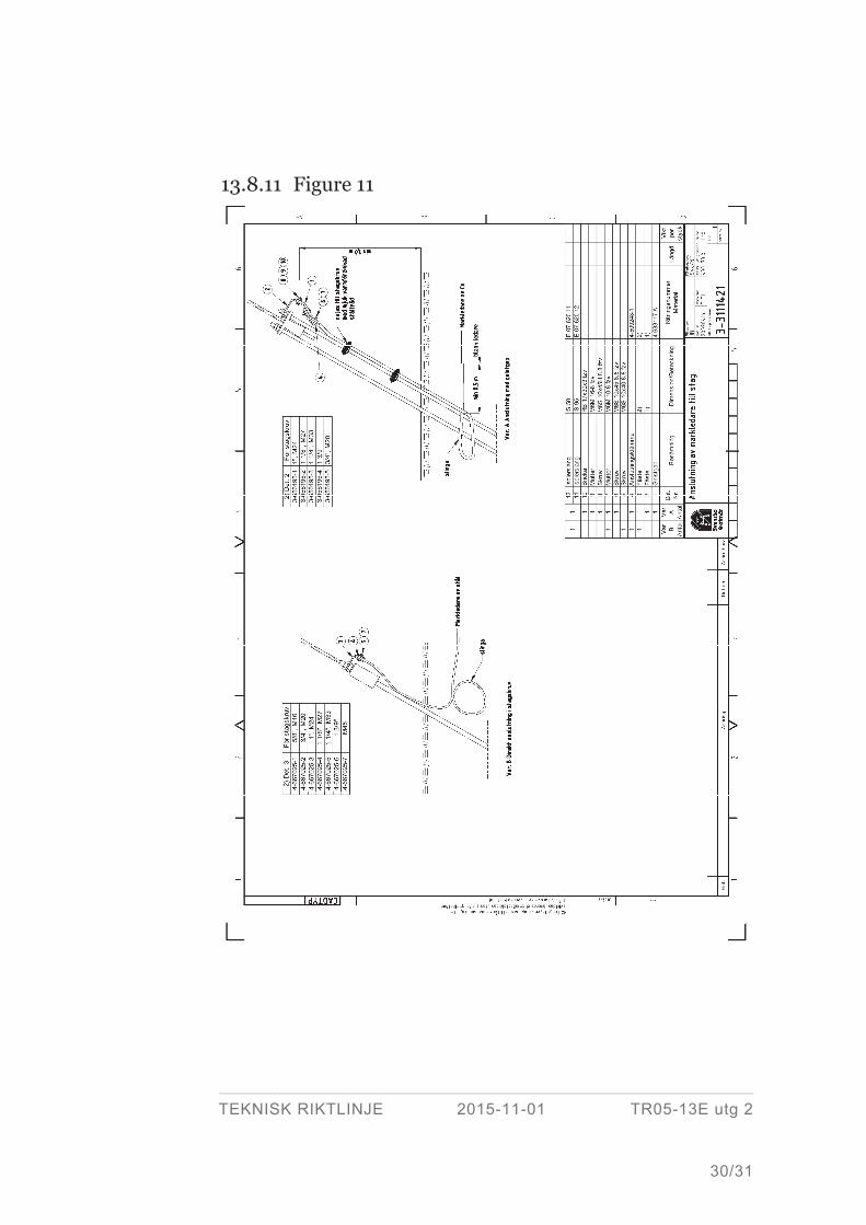
13.5.3.8 Connection of earthing conductors to support and stays Earthing conductor shall be placed in a loop below the ground surface to prevent con-
ductor breakage occurring and also to prevent the conductor from coming loose from
clamps on the tower or stays. See Figure 10 and Figure 11.
Earthing conductors of copper or copper-clad steel shall, both below and above the
ground surface, be insulated with protecting pipe or plastic tube without interruption
to a point at least 0,5 m outside tower legs, foundations, anchor bolt, Potential grading
earth electrode or other steel details. As protecting pipe a pipe of SDR class PE 80
shall be used. The plastic tube shall be black and of a material that is not attacked by
animals or destroyed by frost and low temperature and is stable against UV light. An
example of an approved hose is E0762012.
Earthing conductor of copper-clad steel shall be marked with a sign E0668255. The
sign is placed on the earthing conductor at the connecting to tower/stay.
Support in the ground Support with steel base and/or stay in the ground.
Connection of steel wire is made directly to the support. Connection copper conduc-
tors or copper-clad steel wires are made via spark gap. Spark-gap shall be placed at
least 1,5 m respectively 1,0 m above ground level. See Figure 10 and Figure 11.
TEKNISK RIKTLINJE 2015-11-01 TR05-13E utg 2
17/31
Support on concrete foundation Supports where all the legs and stay rods is connected to a concrete base at least 0,3 m
above ground.
Connection can be made directly (without spark-gaps) if the whole line comprise of
these type of towers even if copper or copper-clad steel wires are used. In this case the
Potential grading earth electrode can be replaced with copper conductor or copper-
clad steel conductor.
If there are towers along the line with support in the ground, the connection shall be
made with spark-gap if copper or copper-clad steel wires are used. See Figure 10 and
Figure 11.
Stays in the ground For support with steel parts and stay placed in the soil, connections are made accord-
ing to the following options:
> Stay insulator mounted on the chosen stay (at new building, stay insulators should
be avoided according to section 13.4.5).
> Steel wires are connected directly to the stay. Connection is made via spark-gap
for copper wire or copper-clad steel wire. The spark-gap shall be at placed least
1,0 m above ground level. See Figure 11
13.5.3.9 Connection to down conductor Connection to down conductor for wood and concrete towers is made according to
Figure 10.
13.5.3.10 Connection and jointing underneath the ground surface Earth conductor is connected to earth electrode and jointing of earth electrodes shall
be performed in such a way that a lasting good contact is obtained and that corrosion
of the connection is prevented. This can be made with crimping (double C-sleeves type
Elpress) or welding.
13.5.3.11 Connection of shield wire
Connection of shield wire Shield wire is connected to the tower as support, suspended or tension wire. In ten-
sion towers is the shield wire connected to an earthing terminal in the tower.
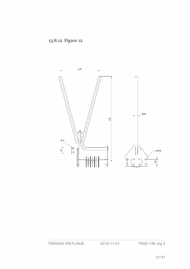
Connection of insulated shield wire Insulated shield wire is to be connected to spark-gap in the tower with an earthing
terminal. Spark-gaps are made according to Figure 12.
TEKNISK RIKTLINJE 2015-11-01 TR05-13E utg 2
18/31
13.5.3.12 Crossings
General Minimum distance between earth electrodes and structures described below are con-
sidered to be indicative only. The measurement of step and touch voltages shall be
carried out to ensure functionality.
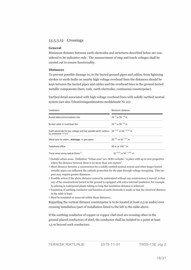
Distances To prevent possible damage to, in the buried ground pipes and cables, from lightning
strokes or earth faults on nearby high voltage overhead lines the distances should be
kept between the buried pipes and cables and the overhead lines in the ground buried
metallic components (bars, rods, earth electrodes, continuous counterpoise).
Earthed detail associated with high voltage overhead lines with solidly earthed neutral
system (see also Telestörningsnämndens meddelande Nr 21):
Installation Minimum distance
Buried telecommunications line 20 3) or 50 1,3) m
Buried cable or overhead line 20 3) or 50 1,3) m
Earth electrode for low voltage and bar parallel earth continu-ity conductor >1 kV
20 2,3,4) or 50 1,2,3,4) m
Metal tube for water-, drainage- or gas pipes 20 2,3) or 50 1,2,3) m
Telephone office 50 m or 100 1) m
Trace wires along optical fibres 5) 20 3,4,5) or 50 1,3,4,5) m
1) Outside urban areas. Definition "Urban area" acc. SCB's website: "A place with up to 200 properties where the distance between them is no more than 200 meters".
2) Short distance between a construction for a solidly earthed neutral system and other longer buried metallic pipes can influence the cathode protection for the pipe through voltage energizing. This im-pact may require greater distances.
3) Possible action if the above distance cannot be maintained without any construction is moved, is that any of the constructions buried in the ground is equipped with extra external insulation, for example by placing in waterproof plastic tubing so long that insulation distance is achieved.
4) Insulation of earthing conductor and location of earth electrode is made so that the electrical distance in the table is kept.
5) Must be insulated or removed within these distances.
Regarding the vertical distance counterpoise is to be located at least 0,5 m under/over
crossing installation/part of installation listed to the left in the table above.
If the earthing conductor of copper or copper-clad steel are crossing other in the
ground placed conductors of steel, the conductor shall be isolated to a point at least
1,5 m beyond such conductors.
TEKNISK RIKTLINJE 2015-11-01 TR05-13E utg 2
19/31
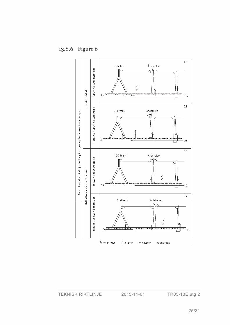
13.5.3.13 Connection between overhead line and substation Connection of to the earthing grid of substation to terminal tower of:
1 steel, for line with shield wire and continuous counterpoise of copper is made
according to Figure 6.
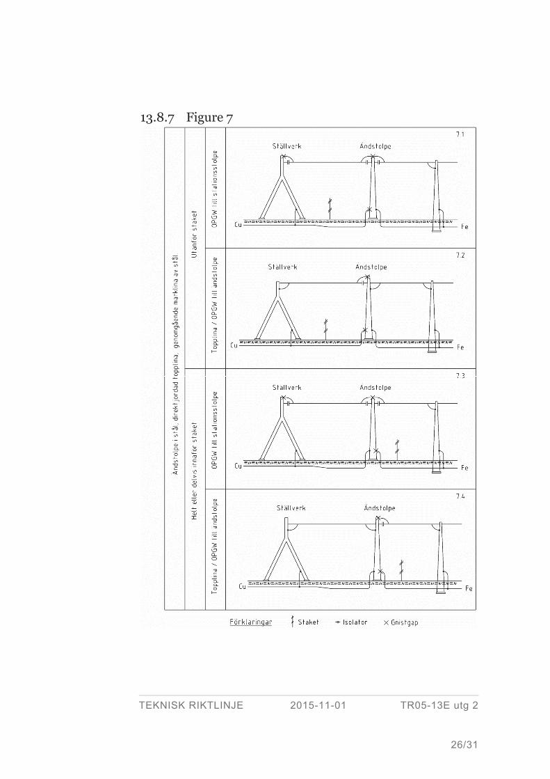
2 steel, for line with shield wire and continuous counterpoise of steel is made ac-
cording to Figure 7.
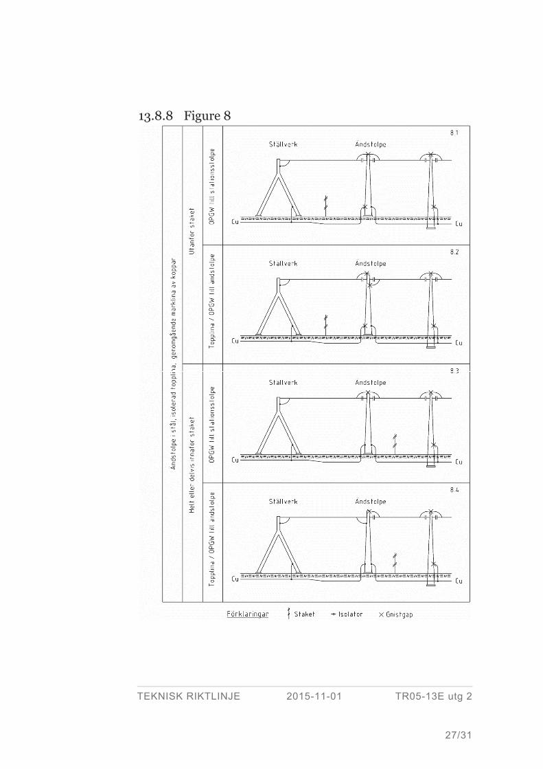
3 steel, for line with insulated shield wire and continuous counterpoise of copper is
made according to Figure 8. These figures shall be seen as an example and in this
design, the entire earthing situation have to be studied.
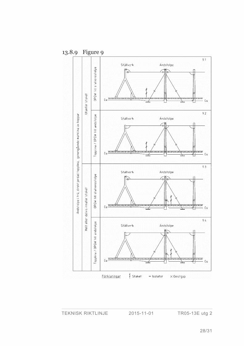
4 wood, for line with shield wire and continuous counterpoise of copper is made
according to Figure 9.
Earthing conductor from the station and the transmission line must have separate
connections on the transmission line end support.
13.6 Check
13.6.1 General Swedish National Electrical Safety Board (Elsäkerhetsverket) requires for the pro-
cessing of the operating permit an account of ground conditions including a specifica-
tion of measured earth resistance and be informed that necessary safety precautions
has been taken at disturbed sites.
Measurements are to be performed according to one of the following two methods;
heavy current method and light current method. All towers (with earth electrodes
taken care of) individual and resultant earth resistance shall be measured and docu-
mented in accordance with SvK-TR08-04.
13.6.2 Heavy current method The check is to determine that the requirements of section 13.4.1 are met. Earthing
resistance measurement is performed in accordance with and ERB U301E and
EBR U602.5.
At new plants the heavy current method of station earthing, and for important parts
along lines. At periodic measurements heavy current method is normally only used for
station earthing. Other tower locations are measured with light current method.
TEKNISK RIKTLINJE 2015-11-01 TR05-13E utg 2
20/31
13.6.3 Light current method The check is to determine that the requirements of section 13.4.1, 13.5.3.3 and 13.5.3.4
are met. Earthing resistance measurement is performed in accordance with and
ERB U301E and EBR U602.5.
On lines with continuous shield wire and with the earth electrode connected without
spark-gap the resulting earthing resistance is measured.
On lines with continuous shield wire and with the earth electrode connected via spark-
gap the earthing resistance of individual earth electrode is measured. To measure the
resulting earth resistance, the spark-gap shall be short-circuited during the measure-
ment.
On lines with insulated shield wire or parts of lines without shield wires earth re-
sistance for individual earth electrode is measured.
At measurements a written protocol shall be used in accordance with EBR U301E.
Appropriate protocol sheet is provided at request from Svenska kraftnät.
13.6.4 Measurement of step and touch voltage The check is intended to determine that the step and touch voltages fulfil the require-
ments of section 13.5.2.5 for the protective earthing of towers.
The heavy current method according to section 13.6.2 shall be used and the control is
normally made for new construction only. In older lines visual inspection of acces-
sions and connections continuity with earth clamp method is made.
13.6.5 Functional check of spark-gap and stay insulator For newly built or rebuilt line a functional check is made with potential measurement
with reference electrode of copper/copper sulphate to the first five towers outside the
switchyard.
Recurrent checks of spark-gap regarding welding, especially after thunderstorms and
nearby earth faults. Checking the spark-gap is made by Svenska kraftnät.
13.7 Delivery
Before handing over, the earthings shall be approved by the orderer. For approval, the
contractor shall demonstrate that the earthing meets the requirements in the guide-
lines.
TEKNISK RIKTLINJE 2015-11-01 TR05-13E utg 2
21/31
The contractor shall provide documentation, in accordance with Svenska kraftnäts
guidelines TR08-04, for approval.
Approval of the documentation does not release the contractor from responsibility that
the earthing fulfils the requirements in the guidelines.
TEKNISK RIKTLINJE 2015-11-01 TR05-13E utg 2
22/31
13.8 Figures
13.8.1 Figure 1
L<a/2
L>a/2
a
Deep earth electrode
TEKNISK RIKTLINJE 2015-11-01 TR05-13E utg 2
23/31
13.8.2 Figure 2
60º
60º
13.8.3 Figure 3
Mittstagad stolpe
Max 25 m
Max 25 m
TEKNISK RIKTLINJE 2015-11-01 TR05-13E utg 2
24/31
13.8.4 Figure 4
0,2-0,3 m
1,5-2,0m 1,5-2,0m
2,0 m
c/c 0,4m
c/c 0,4m
13.8.5 Figure 5
Beröringsskydd
3m3m
TEKNISK RIKTLINJE 2015-11-01 TR05-13E utg 2
25/31
13.8.6 Figure 6
TEKNISK RIKTLINJE 2015-11-01 TR05-13E utg 2
26/31
13.8.7 Figure 7
TEKNISK RIKTLINJE 2015-11-01 TR05-13E utg 2
27/31
13.8.8 Figure 8
TEKNISK RIKTLINJE 2015-11-01 TR05-13E utg 2
28/31
13.8.9 Figure 9
TEKNISK RIKTLINJE 2015-11-01 TR05-13E utg 2
29/31
13.8.10 Figure 10
TEKNISK RIKTLINJE 2015-11-01 TR05-13E utg 2
30/31
13.8.11 Figure 11
TEKNISK RIKTLINJE 2015-11-01 TR05-13E utg 2
31/31
13.8.12 Figure 12